compactrio crio-frc
TRANSCRIPT
OPERATING INSTRUCTIONS AND SPECIFICATIONS
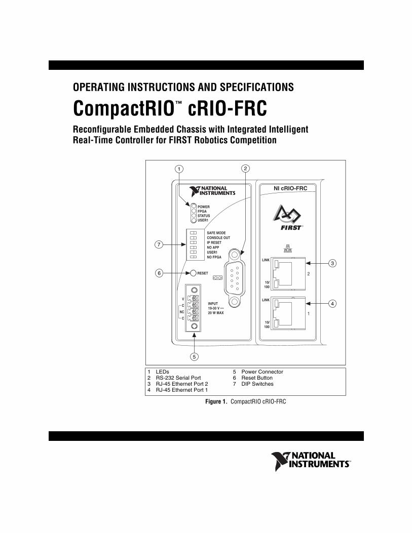
CompactRIO cRIO-FRCReconfigurable Embedded Chassis with Integrated Intelligent Real-Time Controller for FIRST Robotics Competition
Figure 1. CompactRIO cRIO-FRC
1 LEDs2 RS-232 Serial Port3 RJ-45 Ethernet Port 24 RJ-45 Ethernet Port 1
5 Power Connector6 Reset Button7 DIP Switches
™
NI cRIO-FRC
1 2
4
5
6
7
POWERFPGASTATUSUSER1
RESET
LINK
10/100
LINK
10/100
INPUT19-30 V20 W MAX
V
C
NC
C
SAFE MODECONSOLE OUTIP RESETNO APPUSER1NO FPGA
1
2
3
cRIO-FRC Operating Instructions and Specifications 2 ni.com
This document describes how to connect the cRIO-FRC to a network and how to use the features of the cRIO-FRC. This document also contains specifications for the cRIO-FRC.
What You Need to Install the cRIO-FRC❑ FIRST Robotics Electronics kit, including cRIO-FRC reconfigurable
embedded chassis with integrated intelligent real-time controller
❑ C Series I/O modules
❑ DIN rail mount kit (for DIN rail mounting only)
❑ Two M4 or number 10 panhead screws (for panel mounting only)
❑ A number 2 Phillips screwdriver
❑ Power supply
Note The cRIO-FRC may be shipped with a clear protective film cover on the front panel. You can remove the film cover before installing the cRIO-FRC.
Mounting the CompactRIO Reconfigurable Embedded Chassis
You can mount the chassis in any orientation on a 35 mm DIN rail or on a panel. Use the DIN rail mounting method if you already have a DIN rail configuration or if you need to be able to quickly remove the CompactRIO chassis. Use the panel mount method for high shock and vibration applications.
Caution If the ambient operating temperature is 50 °C or higher, you must allow 25.4 mm (1 in.) on the top and bottom of the chassis and in front of the I/O modules for air circulation.
Note You must remove all I/O modules from the chassis before mounting it. Your application may require that one or more of the I/O modules be installed in specific slot locations. Record the slot location of each module before removing the modules from the chassis, and replace each module in the same slot after mounting.
Note The cRIO-FRC is shipped with slot protectors that prevent debris and contaminants from damaging the DB-15 I/O module connectors in unused slots. Do not remove slot protectors from unused slots.
© National Instruments Corporation 3 cRIO-FRC Operating Instructions and Specifications
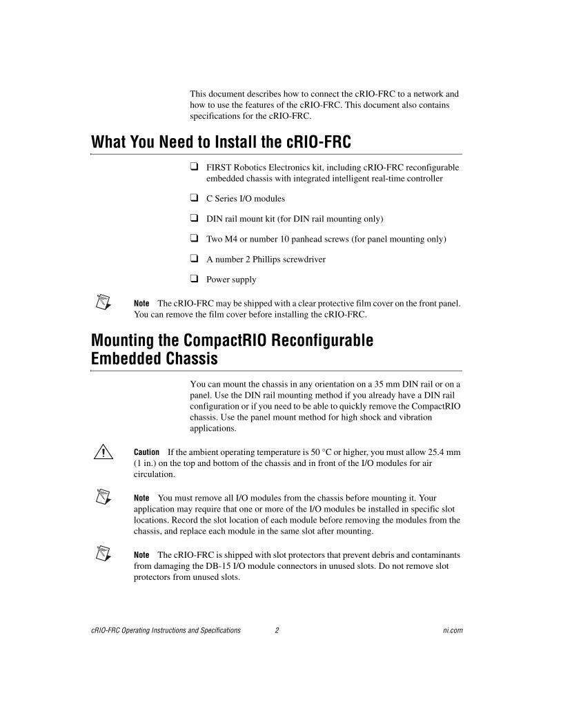
Figure 2. cRIO-FRC, Bottom View with Dimensions
Figure 3. cRIO-FRC, Front View with Dimensions
29 mm(1.14 in.)
58.9 mm(2.32 in.)
3.3 mm(0.13 in.)
286.4 mm(11.28 in.)
Cabling Clearance 25.4 mm (1.00 in.)
87.3 mm(3.44 in.)
165.1 mm(6.50 in.)
3.1 mm(0.12 in.)
51.1 mm(2.04 in.)
36.4 mm(1.43 in.)
19 mm(0.75 in.)
NI cRIO-FRC
12
1
2 3 4 5 6 7 8
cRIO-FRC Operating Instructions and Specifications 4 ni.com
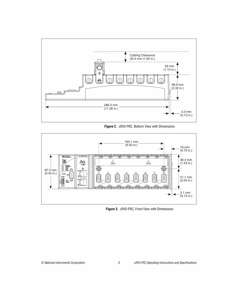
Figure 4. cRIO-FRC, Side View with Dimensions
The following sections contain instructions for the mounting methods. Before using any of these mounting methods, record the serial number from the back of the chassis. You will be unable to read the serial number after you have mounted the chassis.
Caution Make sure that no I/O modules are in the chassis before mounting it.
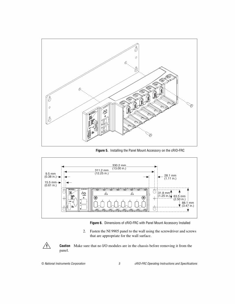
Mounting the Chassis on a PanelYou can use the NI 9905 panel mount kit to mount the cRIO-FRC on a flat surface. Complete the following steps.
1. Fasten the chassis to the panel mount kit using a number 2 Phillips screwdriver and two M4 · 16 screws. National Instruments provides these screws with the panel mount kit. You must use these screws because they are the correct depth and thread for the panel.
3X M4X0.7
25 mm(0.98 in.)
44 mm(1.73 in.)
23.7 mm(0.94 in.)
63.1 mm(2.48 in.)
44.1 mm(1.74 in.)
© National Instruments Corporation 5 cRIO-FRC Operating Instructions and Specifications
Figure 5. Installing the Panel Mount Accessory on the cRIO-FRC
Figure 6. Dimensions of cRIO-FRC with Panel Mount Accessory Installed
2. Fasten the NI 9905 panel to the wall using the screwdriver and screws that are appropriate for the wall surface.
Caution Make sure that no I/O modules are in the chassis before removing it from the panel.
NI cRIO-FRC
2
1
31.8 mm (1.25 in.)
NI cRIO-FRC
15.5 mm (0.61 in.)
9.5 mm (0.38 in.) 28.1 mm
(1.11 in.)
63.5 mm(2.50 in.)
88.1 mm(3.47 in.)
311.2 mm (12.25 in.)
330.2 mm (13.00 in.)
12
1
2 3 4 5 6 7 8
cRIO-FRC Operating Instructions and Specifications 6 ni.com
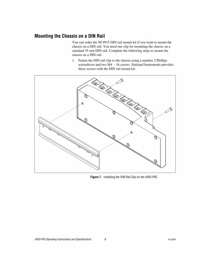
Mounting the Chassis on a DIN RailYou can order the NI 9915 DIN rail mount kit if you want to mount the chassis on a DIN rail. You need one clip for mounting the chassis on a standard 35 mm DIN rail. Complete the following steps to mount the chassis on a DIN rail.
1. Fasten the DIN rail clip to the chassis using a number 2 Phillips screwdriver and two M4 · 16 screws. National Instruments provides these screws with the DIN rail mount kit.
Figure 7. Installing the DIN Rail Clip on the cRIO-FRC
© National Instruments Corporation 7 cRIO-FRC Operating Instructions and Specifications
2. Insert one edge of the DIN rail into the deeper opening of the DIN rail clip, as shown in Figure 8.
Figure 8. One Edge of the DIN Rail Inserted in a Clip
3. Press down firmly on the chassis to compress the spring until the clip locks in place on the DIN rail.
Caution Make sure that no I/O modules are in the chassis before removing it from the DIN rail.
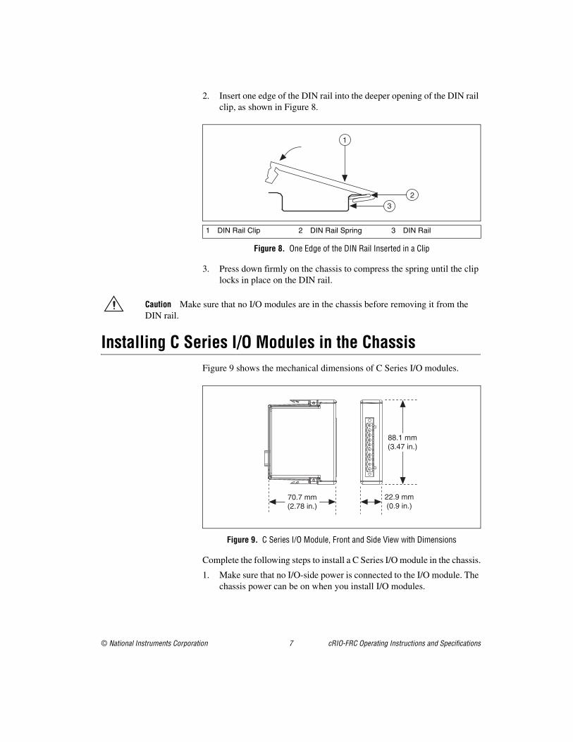
Installing C Series I/O Modules in the ChassisFigure 9 shows the mechanical dimensions of C Series I/O modules.
Figure 9. C Series I/O Module, Front and Side View with Dimensions
Complete the following steps to install a C Series I/O module in the chassis.
1. Make sure that no I/O-side power is connected to the I/O module. The chassis power can be on when you install I/O modules.
1 DIN Rail Clip 2 DIN Rail Spring 3 DIN Rail
2
1
3
88.1 mm(3.47 in.)
70.7 mm(2.78 in.)
22.9 mm(0.9 in.)
cRIO-FRC Operating Instructions and Specifications 8 ni.com
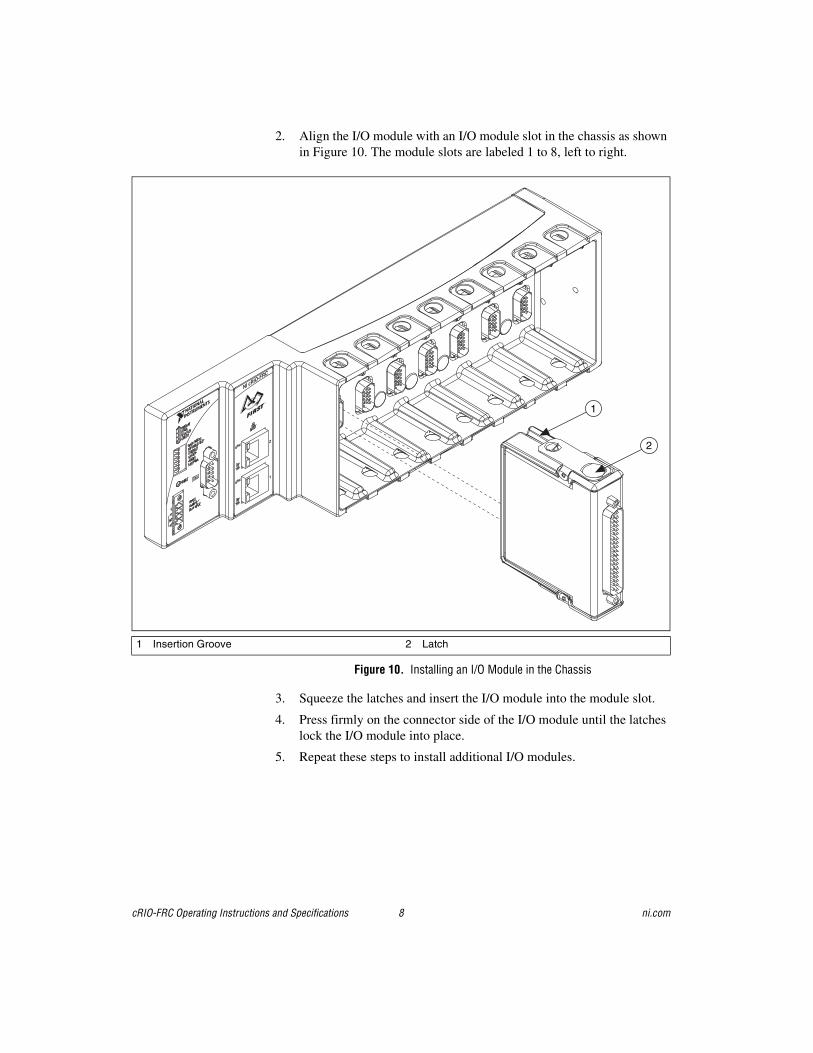
2. Align the I/O module with an I/O module slot in the chassis as shown in Figure 10. The module slots are labeled 1 to 8, left to right.
Figure 10. Installing an I/O Module in the Chassis
3. Squeeze the latches and insert the I/O module into the module slot.
4. Press firmly on the connector side of the I/O module until the latches lock the I/O module into place.
5. Repeat these steps to install additional I/O modules.
1 Insertion Groove 2 Latch
NI cRIO-FRC
1
22
1
© National Instruments Corporation 9 cRIO-FRC Operating Instructions and Specifications
Removing I/O Modules from the ChassisComplete the following steps to remove a C Series I/O module from the chassis.
1. Make sure that no I/O-side power is connected to the I/O module. The chassis power can be on when you remove I/O modules.
2. Squeeze the latches on both sides of the module and pull the module out of the chassis.
Connecting the Chassis to a NetworkConnect the chassis to an Ethernet network using RJ-45 Ethernet port 1 on the controller front panel. Use a standard Category 5 (CAT-5) or better shielded, twisted-pair Ethernet cable to connect the chassis to an Ethernet hub, or use an Ethernet crossover cable to connect the chassis directly to a computer.
Caution To prevent data loss and to maintain the integrity of your Ethernet installation, do not use a cable longer than 100 m.
If you need to build your own cable, refer to the Cabling section for more information about Ethernet cable wiring connections.
The host computer communicates with the chassis over a standard Ethernet connection. If the host computer is on a network, you must configure the chassis on the same subnet as the host computer. If neither the host computer nor the chassis is connected to a network, you can connect the two directly using a crossover cable.
If you want to use the chassis on a subnet other than the one the host computer is on, first connect the chassis on the same subnet as the host computer. Use DHCP to assign an IP address or reassign a static IP address for the subnet where you want it to be and physically move it to the other subnet. The first time you configure the chassis, you must also install software on it. Refer to the Measurement & Automation Explorer Help for more information about installing software on and configuring the chassis in Measurement & Automation Explorer (MAX). Contact your network administrator if you need assistance configuring the host computer and chassis on the same subnet.
cRIO-FRC Operating Instructions and Specifications 10 ni.com
Wiring Power to the ChassisThe cRIO-FRC requires an external power supply that meets the specifications in the Power Requirements section. The cRIO-FRC filters and regulates the supplied power and provides power for all of the I/O modules. The cRIO-FRC has one layer of reverse-voltage protection. Complete the following steps to connect a power supply to the chassis.
1. Connect the positive lead of the power supply to the V terminal of the COMBICON connector shipped with the cRIO-FRC.
2. Connect the negative lead of the power supply to one of the C terminals of the COMBICON connector.
3. Install the COMBICON connector on the front panel of the cRIO-FRC and tighten the screws on the connector.
Caution The C terminals are internally connected to each other.
Caution Do not disconnect the power supply wires and connectors from the controller unless power has been switched off.
Powering On the cRIO-FRCWhen you apply power to the cRIO-FRC, the controller runs a power-on self test (POST). During the POST, the Power and Status LEDs turn on. The Status LED turns off, indicating that the POST is complete. If the LEDs do not behave in this way when the system powers on, refer to the Understanding LED Indications section.
You can configure the cRIO-FRC to launch an embedded stand-alone LabVIEW RT application each time you boot the controller. Refer to the Running a Stand-Alone Real-Time Application (RT Module) topic of the LabVIEW Help for more information.
You can also configure the cRIO-FRC to launch an embedded stand-alone C/C++ application each time you boot the controller. Refer to the Robot Programming with the WPI Robotics Library document for more information.
Boot OptionsTable 1 lists the reset options available on CompactRIO systems such as the cRIO-FRC. These options are used to determine how the FPGA behaves when the controller is reset in various conditions.
© National Instruments Corporation 11 cRIO-FRC Operating Instructions and Specifications
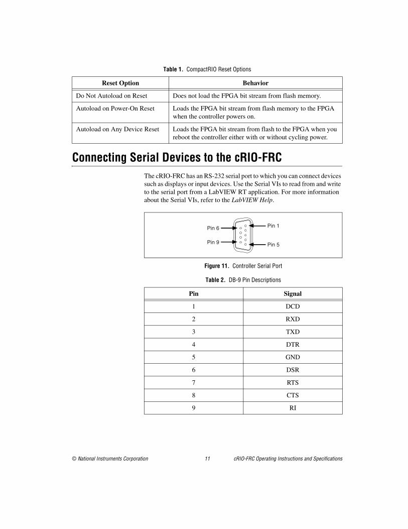
Connecting Serial Devices to the cRIO-FRCThe cRIO-FRC has an RS-232 serial port to which you can connect devices such as displays or input devices. Use the Serial VIs to read from and write to the serial port from a LabVIEW RT application. For more information about the Serial VIs, refer to the LabVIEW Help.
Figure 11. Controller Serial Port
Table 1. CompactRIO Reset Options
Reset Option Behavior
Do Not Autoload on Reset Does not load the FPGA bit stream from flash memory.
Autoload on Power-On Reset Loads the FPGA bit stream from flash memory to the FPGA when the controller powers on.
Autoload on Any Device Reset Loads the FPGA bit stream from flash to the FPGA when you reboot the controller either with or without cycling power.
Table 2. DB-9 Pin Descriptions
Pin Signal
1 DCD
2 RXD
3 TXD
4 DTR
5 GND
6 DSR
7 RTS
8 CTS
9 RI
Pin 1
Pin 5
Pin 6
Pin 9
cRIO-FRC Operating Instructions and Specifications 12 ni.com
Using the Internal Real-Time ClockThe system clock of the cRIO-FRC is synchronized with the internal high-precision real-time clock at startup. This synchronization provides timestamp data to the controller. You can also use the internal real-time clock to correct drift of the system clock. Refer to the Internal Real-Time Clock specification in the Specifications section for the accuracy specifications of the real-time clock.
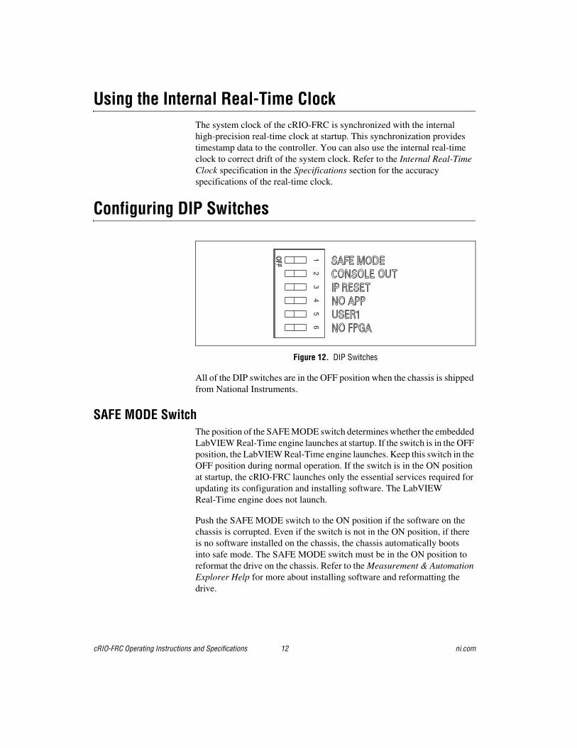
Configuring DIP Switches
Figure 12. DIP Switches
All of the DIP switches are in the OFF position when the chassis is shipped from National Instruments.
SAFE MODE SwitchThe position of the SAFE MODE switch determines whether the embedded LabVIEW Real-Time engine launches at startup. If the switch is in the OFF position, the LabVIEW Real-Time engine launches. Keep this switch in the OFF position during normal operation. If the switch is in the ON position at startup, the cRIO-FRC launches only the essential services required for updating its configuration and installing software. The LabVIEW Real-Time engine does not launch.
Push the SAFE MODE switch to the ON position if the software on the chassis is corrupted. Even if the switch is not in the ON position, if thereis no software installed on the chassis, the chassis automatically boots into safe mode. The SAFE MODE switch must be in the ON position to reformat the drive on the chassis. Refer to the Measurement & Automation Explorer Help for more about installing software and reformatting the drive.
1 6
5 4
3 2
© National Instruments Corporation 13 cRIO-FRC Operating Instructions and Specifications
CONSOLE OUT SwitchWith a serial-port terminal program, you can use the CONSOLE OUT switch to read the IP address and firmware version of the controller. Use a null-modem cable to connect the serial port on the chassis to a computer. Push the switch to the ON position. Make sure that the serial-port terminal program is configured to the following settings:
• 9,600 bits per second
• Eight data bits
• No parity
• One stop bit
• No flow control
The serial-port terminal program displays the IP address and firmware version of the chassis. Keep this switch in the OFF position during normal operation.
IP RESET SwitchPush the IP RESET switch to the ON position and reboot the chassis to reset the IP address to 0.0.0.0. If the chassis is on your local subnet and the IP RESET switch is in the ON position, the chassis appears in MAX with IP address 0.0.0.0. You can configure a new IP address for the chassis in MAX. Refer to the Resetting the Network Configuration of the cRIO-FRC section for more information about resetting the IP address. You also can push this switch to the ON position to unlock a chassis that was previously locked in MAX.
NO APP SwitchPush the NO APP switch to the ON position to prevent a LabVIEW RT startup application from running at startup. If you want to permanently disable a LabVIEW RT application from running at startup, you must disable it in LabVIEW. To run an application at startup, push the NO APP switch to the OFF position, create an application using the LabVIEW Application Builder, and configure the application in LabVIEW to launch at startup. If you already have an application configured to launch at startup and you push the NO APP switch from ON to OFF, the startup application is automatically enabled. For more information about automatically launching VIs at startup and disabling VIs from launching at startup, refer to the Running a Stand-Alone Real-Time Application (RT Module) topic of the LabVIEW Help.
The NO APP switch does not affect C/C++ startup applications. You can use the Undeploy option in Wind River Workbench to disable a C/C++ application.
cRIO-FRC Operating Instructions and Specifications 14 ni.com
USER1 SwitchYou can define the USER1 switch for your application. To define the purpose of this switch in your embedded application, use the RT Read Switch VI in your LabVIEW RT embedded VI. For more information about the RT Read Switch VI, refer to the LabVIEW Help.
NO FPGA SwitchPush the NO FPGA switch to the ON position to prevent a LabVIEW FPGA application from loading at startup. The NO FPGA switch overrides the CompactRIO reset options described in the Boot Options section. After startup you can download to the FPGA from software regardless of switch position.
Using the RESET ButtonPressing the RESET button resets the processor in the same manner as cycling power.
Note The FPGA continues to run unless you select the Autoload on Any Device Reset boot option. Refer to the Boot Options section for more information.
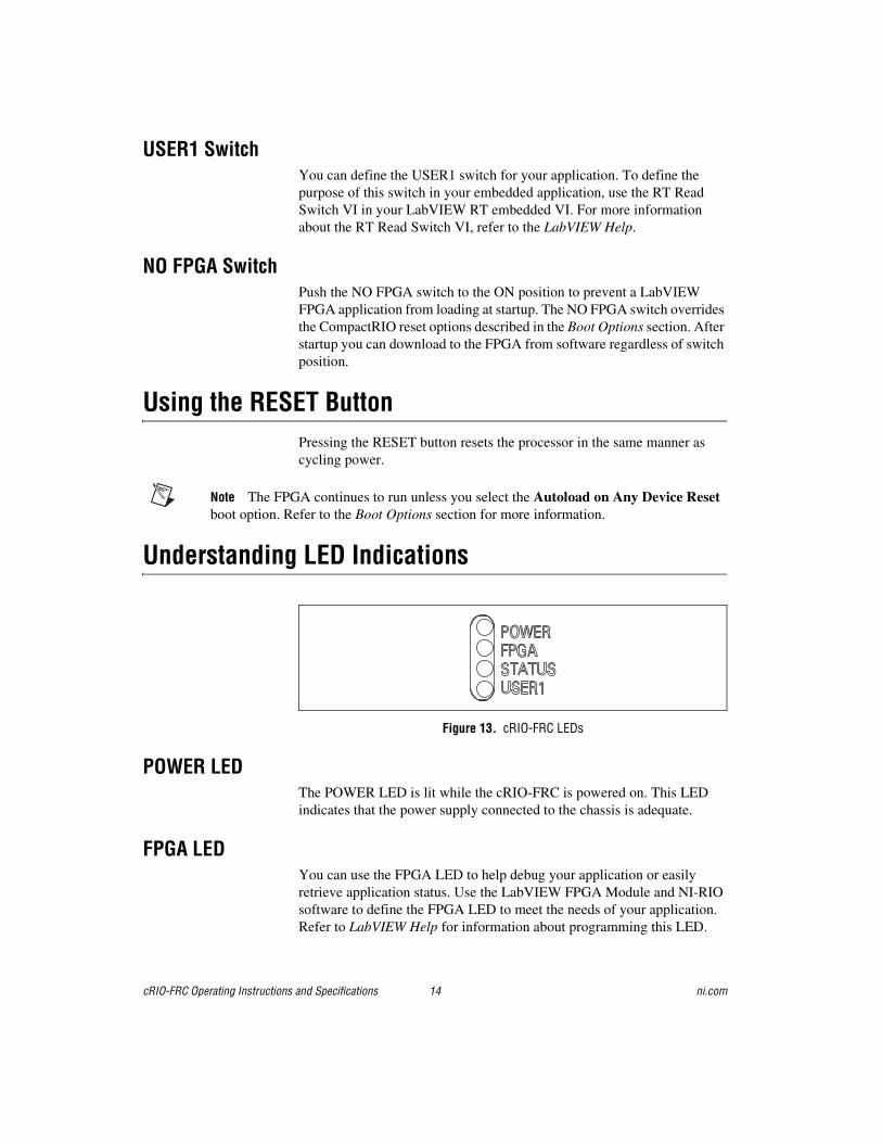
Understanding LED Indications
Figure 13. cRIO-FRC LEDs
POWER LEDThe POWER LED is lit while the cRIO-FRC is powered on. This LED indicates that the power supply connected to the chassis is adequate.
FPGA LEDYou can use the FPGA LED to help debug your application or easily retrieve application status. Use the LabVIEW FPGA Module and NI-RIO software to define the FPGA LED to meet the needs of your application. Refer to LabVIEW Help for information about programming this LED.
© National Instruments Corporation 15 cRIO-FRC Operating Instructions and Specifications
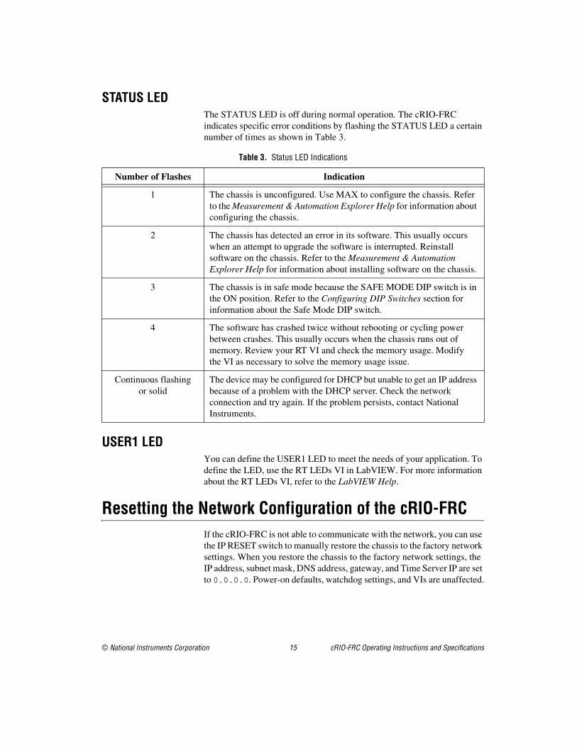
STATUS LEDThe STATUS LED is off during normal operation. The cRIO-FRC indicates specific error conditions by flashing the STATUS LED a certain number of times as shown in Table 3.
USER1 LEDYou can define the USER1 LED to meet the needs of your application. To define the LED, use the RT LEDs VI in LabVIEW. For more information about the RT LEDs VI, refer to the LabVIEW Help.
Resetting the Network Configuration of the cRIO-FRCIf the cRIO-FRC is not able to communicate with the network, you can use the IP RESET switch to manually restore the chassis to the factory network settings. When you restore the chassis to the factory network settings, the IP address, subnet mask, DNS address, gateway, and Time Server IP are set to 0.0.0.0. Power-on defaults, watchdog settings, and VIs are unaffected.
Table 3. Status LED Indications
Number of Flashes Indication
1 The chassis is unconfigured. Use MAX to configure the chassis. Refer to the Measurement & Automation Explorer Help for information about configuring the chassis.
2 The chassis has detected an error in its software. This usually occurs when an attempt to upgrade the software is interrupted. Reinstall software on the chassis. Refer to the Measurement & Automation Explorer Help for information about installing software on the chassis.
3 The chassis is in safe mode because the SAFE MODE DIP switch is in the ON position. Refer to the Configuring DIP Switches section for information about the Safe Mode DIP switch.
4 The software has crashed twice without rebooting or cycling power between crashes. This usually occurs when the chassis runs out of memory. Review your RT VI and check the memory usage. Modify the VI as necessary to solve the memory usage issue.
Continuous flashing or solid
The device may be configured for DHCP but unable to get an IP address because of a problem with the DHCP server. Check the network connection and try again. If the problem persists, contact National Instruments.
cRIO-FRC Operating Instructions and Specifications 16 ni.com
Complete the following steps to reset the chassis.
1. Move the IP RESET DIP switch to the ON position.
2. Push the RESET button to cycle power to the chassis. The STATUS LED flashes once, indicating that the IP address is unconfigured.
3. Move the IP RESET switch to the OFF position.
The network settings are restored. You can reconfigure the settings in MAX from a computer on the same subnet. Refer to the Measurement & Automation Explorer Help for more information about configuring the chassis.
Note If the chassis is restored to the factory network settings, the LabVIEW run-time engine does not load. You must reconfigure the network settings and restart the chassis for the LabVIEW run-time engine to load.
SpecificationsThe following specifications are typical for the –20 to 55 °C operating temperature range unless otherwise noted.
NetworkNetwork interface ...................................10BaseT and 100BaseTX
Ethernet
Compatibility ..........................................IEEE 802.3
Communication rates ..............................10 Mbps, 100 Mbps, auto-negotiated
Maximum cabling distance.....................100 m/segment
RS-232 Serial Port
Maximum baud rate................................115,200 bps
Data bits ..................................................5, 6, 7, 8
Stop bits ..................................................1, 2
Parity.......................................................Odd, Even, Mark, Space
Flow control............................................RTS/CTS, XON/XOFF, DTR/DSR
© National Instruments Corporation 17 cRIO-FRC Operating Instructions and Specifications
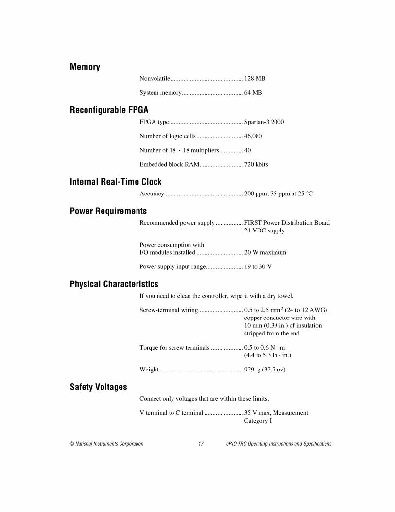
MemoryNonvolatile............................................. 128 MB
System memory...................................... 64 MB
Reconfigurable FPGAFPGA type.............................................. Spartan-3 2000
Number of logic cells ............................. 46,080
Number of 18 · 18 multipliers .............. 40
Embedded block RAM........................... 720 kbits
Internal Real-Time ClockAccuracy ................................................ 200 ppm; 35 ppm at 25 °C
Power RequirementsRecommended power supply ................. FIRST Power Distribution Board
24 VDC supply
Power consumption with I/O modules installed ............................. 20 W maximum
Power supply input range....................... 19 to 30 V
Physical CharacteristicsIf you need to clean the controller, wipe it with a dry towel.
Screw-terminal wiring............................ 0.5 to 2.5 mm2 (24 to 12 AWG) copper conductor wire with 10 mm (0.39 in.) of insulation stripped from the end
Torque for screw terminals .................... 0.5 to 0.6 N · m (4.4 to 5.3 lb · in.)
Weight .................................................... 929 g (32.7 oz)
Safety VoltagesConnect only voltages that are within these limits.
V terminal to C terminal ........................ 35 V max, Measurement Category I
cRIO-FRC Operating Instructions and Specifications 18 ni.com
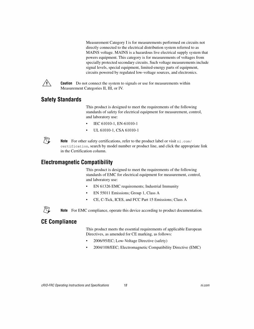
Measurement Category I is for measurements performed on circuits not directly connected to the electrical distribution system referred to as MAINS voltage. MAINS is a hazardous live electrical supply system that powers equipment. This category is for measurements of voltages from specially protected secondary circuits. Such voltage measurements include signal levels, special equipment, limited-energy parts of equipment, circuits powered by regulated low-voltage sources, and electronics.
Caution Do not connect the system to signals or use for measurements within Measurement Categories II, III, or IV.
Safety StandardsThis product is designed to meet the requirements of the following standards of safety for electrical equipment for measurement, control, and laboratory use:
• IEC 61010-1, EN-61010-1
• UL 61010-1, CSA 61010-1
Note For other safety certifications, refer to the product label or visit ni.com/certification, search by model number or product line, and click the appropriate link in the Certification column.
Electromagnetic CompatibilityThis product is designed to meet the requirements of the following standards of EMC for electrical equipment for measurement, control, and laboratory use:
• EN 61326 EMC requirements; Industrial Immunity
• EN 55011 Emissions; Group 1, Class A
• CE, C-Tick, ICES, and FCC Part 15 Emissions; Class A
Note For EMC compliance, operate this device according to product documentation.
CE ComplianceThis product meets the essential requirements of applicable European Directives, as amended for CE marking, as follows:
• 2006/95/EC; Low-Voltage Directive (safety)
• 2004/108/EEC; Electromagnetic Compatibility Directive (EMC)
© National Instruments Corporation 19 cRIO-FRC Operating Instructions and Specifications
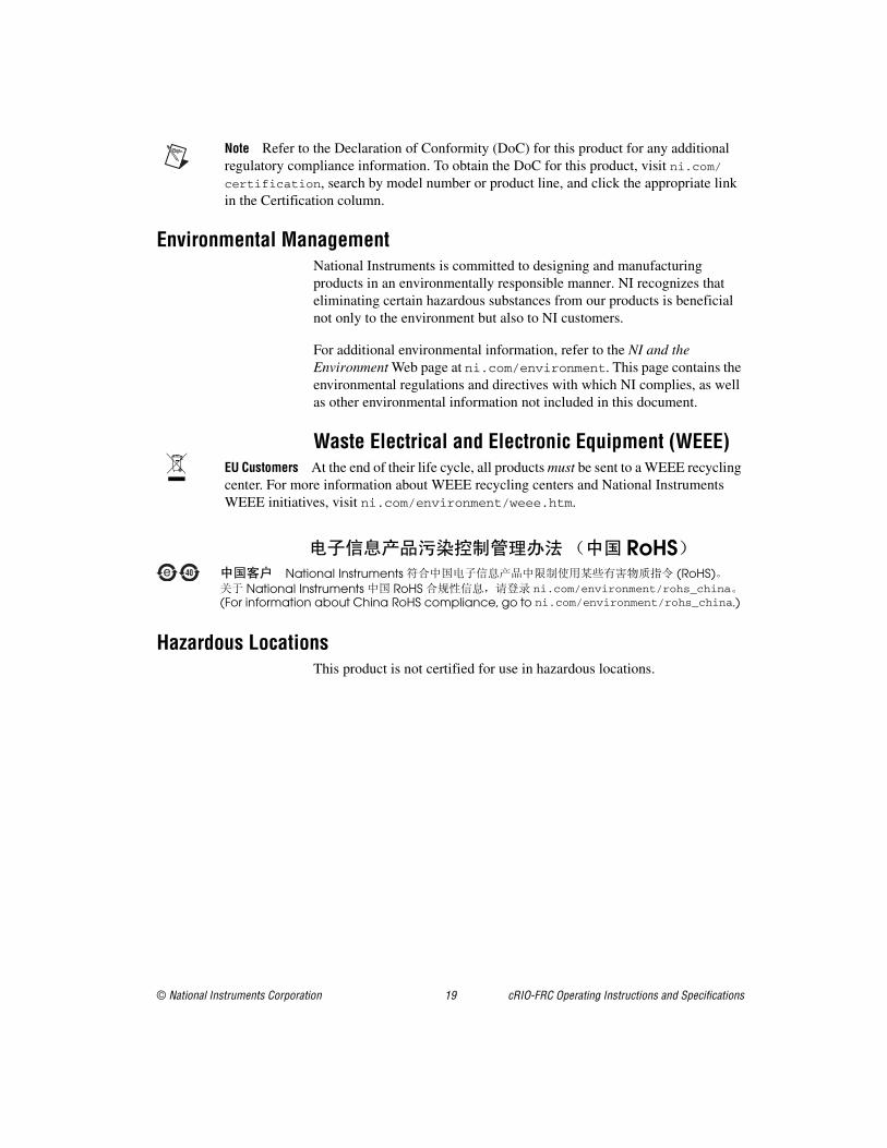
Note Refer to the Declaration of Conformity (DoC) for this product for any additional regulatory compliance information. To obtain the DoC for this product, visit ni.com/certification, search by model number or product line, and click the appropriate link in the Certification column.
Environmental ManagementNational Instruments is committed to designing and manufacturing products in an environmentally responsible manner. NI recognizes that eliminating certain hazardous substances from our products is beneficial not only to the environment but also to NI customers.
For additional environmental information, refer to the NI and the Environment Web page at ni.com/environment. This page contains the environmental regulations and directives with which NI complies, as well as other environmental information not included in this document.
Waste Electrical and Electronic Equipment (WEEE)EU Customers At the end of their life cycle, all products must be sent to a WEEE recycling center. For more information about WEEE recycling centers and National Instruments WEEE initiatives, visit ni.com/environment/weee.htm.
Hazardous LocationsThis product is not certified for use in hazardous locations.
RoHSNational Instruments (RoHS)
National Instruments RoHS ni.com/environment/rohs_china(For information about China RoHS compliance, go to ni.com/environment/rohs_china.)
cRIO-FRC Operating Instructions and Specifications 20 ni.com
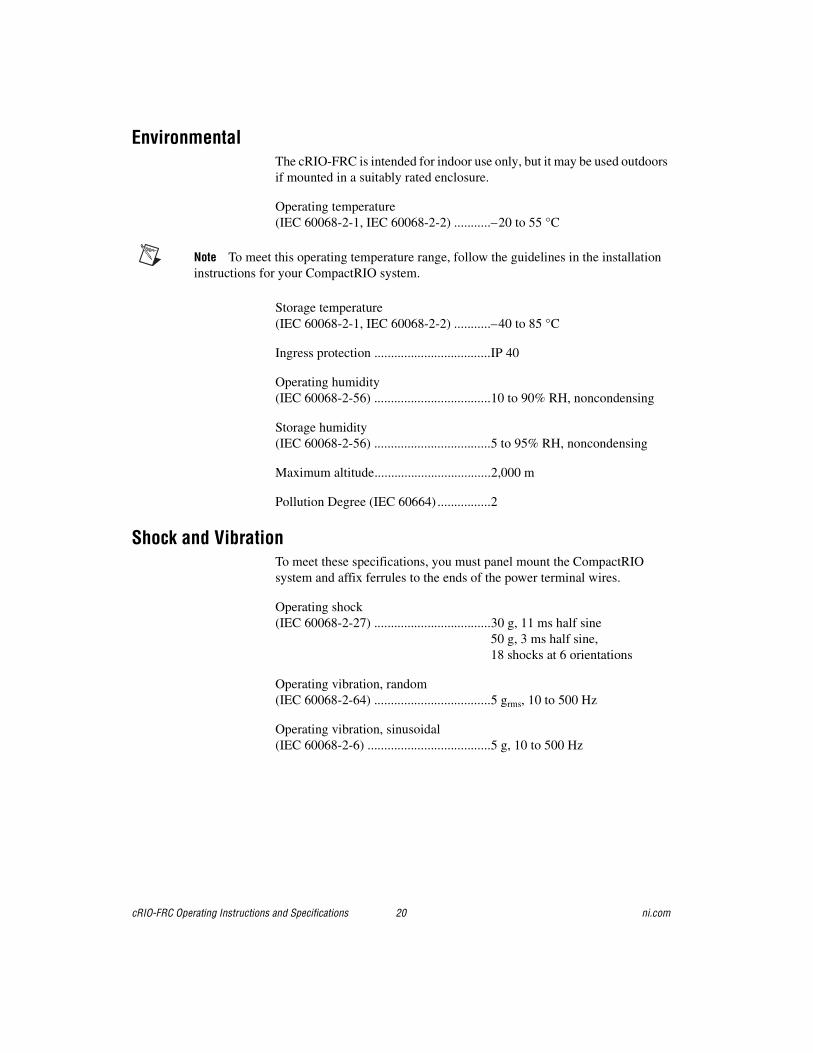
EnvironmentalThe cRIO-FRC is intended for indoor use only, but it may be used outdoors if mounted in a suitably rated enclosure.
Operating temperature(IEC 60068-2-1, IEC 60068-2-2) ...........–20 to 55 °C
Note To meet this operating temperature range, follow the guidelines in the installation instructions for your CompactRIO system.
Storage temperature(IEC 60068-2-1, IEC 60068-2-2) ...........–40 to 85 °C
Ingress protection ...................................IP 40
Operating humidity(IEC 60068-2-56) ...................................10 to 90% RH, noncondensing
Storage humidity(IEC 60068-2-56) ...................................5 to 95% RH, noncondensing
Maximum altitude...................................2,000 m
Pollution Degree (IEC 60664) ................2
Shock and VibrationTo meet these specifications, you must panel mount the CompactRIO system and affix ferrules to the ends of the power terminal wires.
Operating shock(IEC 60068-2-27) ...................................30 g, 11 ms half sine
50 g, 3 ms half sine,18 shocks at 6 orientations
Operating vibration, random (IEC 60068-2-64) ...................................5 grms, 10 to 500 Hz
Operating vibration, sinusoidal(IEC 60068-2-6) .....................................5 g, 10 to 500 Hz
© National Instruments Corporation 21 cRIO-FRC Operating Instructions and Specifications
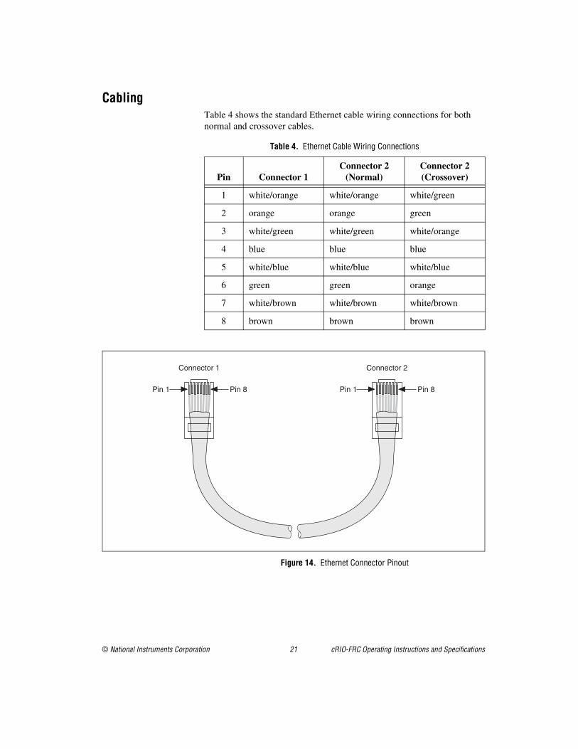
CablingTable 4 shows the standard Ethernet cable wiring connections for both normal and crossover cables.
Figure 14. Ethernet Connector Pinout
Table 4. Ethernet Cable Wiring Connections
Pin Connector 1Connector 2
(Normal)Connector 2 (Crossover)
1 white/orange white/orange white/green
2 orange orange green
3 white/green white/green white/orange
4 blue blue blue
5 white/blue white/blue white/blue
6 green green orange
7 white/brown white/brown white/brown
8 brown brown brown
Connector 1 Connector 2
Pin 1 Pin 1 Pin 8 Pin 8

cRIO-FRC Operating Instructions and Specifications 22 ni.com
Where to Go for SupportThe National Instruments Web site is your complete resource for technical support. At ni.com/support you have access to everything from troubleshooting and application development self-help resources to email and phone assistance from NI Application Engineers.
National Instruments corporate headquarters is located at 11500 North Mopac Expressway, Austin, Texas, 78759-3504. National Instruments also has offices located around the world to help address your support needs. For telephone support in the United States, create your service request at ni.com/support and follow the calling instructions or dial 512 795 8248. For telephone support outside the United States, contact your local branch office:
Australia 1800 300 800, Austria 43 662 457990-0, Belgium 32 (0) 2 757 0020, Brazil 55 11 3262 3599, Canada 800 433 3488, China 86 21 5050 9800, Czech Republic 420 224 235 774, Denmark 45 45 76 26 00, Finland 358 (0) 9 725 72511, France 01 57 66 24 24, Germany 49 89 7413130, India 91 80 41190000, Israel 972 3 6393737, Italy 39 02 41309277, Japan 0120-527196, Korea 82 02 3451 3400, Lebanon 961 (0) 1 33 28 28, Malaysia 1800 887710, Mexico 01 800 010 0793, Netherlands 31 (0) 348 433 466, New Zealand 0800 553 322, Norway 47 (0) 66 90 76 60, Poland 48 22 3390150, Portugal 351 210 311 210, Russia 7 495 783 6851, Singapore 1800 226 5886, Slovenia 386 3 425 42 00, South Africa 27 0 11 805 8197, Spain 34 91 640 0085, Sweden 46 (0) 8 587 895 00, Switzerland 41 56 2005151, Taiwan 886 02 2377 2222, Thailand 662 278 6777, Turkey 90 212 279 3031, United Kingdom 44 (0) 1635 523545

© National Instruments Corporation 23 cRIO-FRC Operating Instructions and Specifications

National Instruments, NI, ni.com, and LabVIEW are trademarks of National Instruments Corporation. Refer to the Terms of Use section on ni.com/legal for more information about National Instruments trademarks. Other product and company names mentioned herein are trademarks or trade names of their respective companies. For patents covering National Instruments products, refer to the appropriate location: Help»Patents in your software, the patents.txt file on your media, or ni.com/patents.
© 2008 National Instruments Corporation. All rights reserved. 325075A-01 Oct08
*325075A-01*