company operations facility (cof) statement … army corps of engineers... · 1 revision 3.8 dated...
TRANSCRIPT

Revision 3.8 Dated 23 January 20121
DEPARTMENT OF THE ARMYFACILITIES STANDARDIZATION
PROGRAM
COMPANY OPERATIONS FACILITY
(COF)
STATEMENT OF WORK
23 January 2012
Revision 3.8 Dated 23 January 20122
1.0 PROJECT OBJECTIVES
The project objective is to design and construct facilities for the military that are consistent with the design and construction practices used for civilian sector projects that perform similar functions to the military projects. For example, a Company Operations Facility has the similar function as an office/warehouse in the civilian sector; therefore the design and construction practices should be consistent with the design and construction of an office/warehouse building.
Comparison of Military Facilities to Civilian Facilities
Military Facility Civilian Facility
Company Operations Facility (COF) Office/Warehouse
It is the Army’s objective that these buildings will have a 25-year useful life before needing any major renovation, repair, or replacement. Therefore, the design and construction should provide an appropriate level of quality to ensure the continued use of the facility over that time period with the application of reasonable preventive maintenance and repairs that would be industry-acceptable to a major civilian sector project OWNER. The site infrastructure will have at least a 50-year life expectancy with industry-accepted maintenance and repair cycles.
The government is required by Public Law 102-486, Executive Order 12902, and Federal Regulations 10 CFR 435 to design and construct facilities in an energy-conserving manner while considering life cycle cost over the life of the facilities.
The project site should be developed for efficiency and to convey a sense of unity or connectivity with the adjacent buildings and with the Installation as a whole.
Requirements stated in this RFP are minimums. Innovative, creative, and life cycle cost effective solutions, which meet or exceed these requirements are encouraged. Further, the OFFEROR is encouraged to seek solutions that will expedite construction (panelization, pre-engineered, etc.) and shorten the schedule. The intent of the Government is to emphasize the placement of funds into functional/operational requirements. Materials and methods should reflect this by choosing the lowest Type of Construction allowed by code for this occupancy/project allowing the funding to be reflected in the quality of interior/exterior finishes and systems selected.
2.0 SCOPE
2.1 COMPANY OPERATIONS FACILITY (COF)
Provide Company Operations Facilities (COF). This project type is to house Company administrative operations and store and move supplies. It is intended to be similar to office and warehouse type buildings in the private sector community.
Revision 3.8 Dated 23 January 20123
The project will include Company Operations Facilities for [_____] Companies. The number of unified companies (UNICOF) per battalion and number of personnel per company for this project is as follows:
[UNICOF/Unit Identifier
Company [COF_CO_LETTER] = [COF_CO_PERSONNEL] Personnel, male/female ratio [COF_CO_RATIO]
]
The maximum allowable gross area for the Admin Module is [_____] square feet.
The maximum allowable gross area for the Readiness Module is [_____] square feet.
The maximum allowable gross exterior covered hardstand area is [_____] square feet.
A Troop Aid Station to support the Brigade [is] [is not] required [and will be included in the [___] UNICOF].
The preferred design approach for this complex is the [UNICOF with detached two-story admin] [UNICOF with integrated admin] layout scheme.
2.2 SITE
Provide all site design and construction within the COF limits of construction necessary to support the new building facilities. Supporting facilities include, but are not limited to, utilities, electric service, exterior and security lighting, fire protection and alarm systems, security fencing and gates, water, gas, sewer, oil water separators, storm drainage and site improvements. Antiterrorism/Force Protection measures shall also be included in the facility design in accordance with applicable criteria.
The Contractor shall be responsible for maintaining the construction site and haul route. Damages to existing sidewalks, pavements, curb and gutter, utilities, and/or landscaping within the construction limit, adjacent to the construction site, and along the Contractor’s haul route resulting from the Contractor’s construction activities shall be repair/replace by the Contractor at no additional cost to the Government. Prior to construction activities, the Contractor and Contracting Officer Representative shall perform an existing condition survey. At the completion of the Task Order, the Contractor and Contracting Officer Representative shall perform a final condition survey to determine repair/replacement requirements.
Approximate area available for [this facility] [these facilities] is shown on the drawings.
2.3 GOVERNMENT-FURNISHED GOVERNMENT-INSTALLED EQUIPMENT (GFGI)
Coordinate with Government on GFGI item requirements and provide suitable structural support, brackets for projectors/VCRs/TVs, all utility connections and space with required clearances for all GFGI items. All computers and related hardware, copiers, faxes, printers, video projectors, VCRs and TVs are GFGI.
2.4 FURNITURE REQUIREMENTS
Provide furniture design for all spaces, including existing furniture and equipment to be re-used. Coordinate with the user to define requirements for furniture systems, movable furniture, equipment, existing items to be re-used, storage systems, etc. Early coordination of furniture schedule is required so the facility is complete and usable at turnover. Furniture procurement is not included in this contract.
3.0 FUNCTIONAL AND AREA REQUIREMENTS FOR COMPANY OPERATIONS FACILITY (COF)
Revision 3.8 Dated 23 January 20124
3.1 General Requirements
COFs provide administrative and supply facilities for unit personnel functions and storage of their equipment. These facilities serve as the primary staging, training, and deployment center for personnel and their individualized gear.
3.1.1 Facility Relationships
COFs are typically located within an operations complex along with Tactical Equipment Maintenance Facilities (motor pools) and Battalion/Brigade HQ. The facilities within this complex shall be oriented to support deployment and daily operations, and should also be located within walking distance of associated community facilities such as barracks and dining facilities.
3.1.2 Gross Building Area
Gross areas of facilities shall be computed according to subparagraphs below. Maximum gross area limits indicated in Paragraph 2.0, SCOPE, may not be exceeded. A smaller overall gross area is permissible if all established net area program requirements are met.
(1) Enclosed Spaces. The gross area includes the total area of all floors, including basements, mezzanines, penthouses, usable attic or sloping spaces used to accommodate mechanical equipment or for storage with an average height of 6’-11” measured from the underside of the structural system and with the perimeter walls measuring a minimum of 4’-11” in height, and other enclosed spaces as determined by the effective outside dimensions of the building. (NOTE: Exterior Covered Hardstand area associated with Company Operations Facilities shall be calculated as enclosed space, i.e. full scope).
(2) One-Half Spaces. One-half of the area will be included in the gross area for balconies and porches; exterior covered loading platforms or facilities, either depressed, ground level, or raised; covered but not enclosed passageways or walks; covered and uncovered but open stairs; and covered ramps.
(3) Excluded Spaces. Crawl spaces; exterior uncovered loading platforms or facilities, either depressed, ground level, or raised; exterior insulation applied to existing buildings; open courtyards; open paved terraces’; roof overhangs and soffits for weather protection; uncovered ramps; uncovered stoops; and utility tunnels and raceways will be excluded from the gross area.
3.1.3 Functional Spaces
Net area requirements for functional spaces are included in the space program table (Table 2). If net area requirements are not specified in the Statement of Work, the space shall be sized to accommodate the required function, comply with code requirements, comply with overall gross area limitations and other requirements of the RFP (for example, area requirements for corridors, stairs, and mechanical rooms will typically be left to the discretion of the Offeror).
3.1.4 Handicapped Access
COFs are intended for use by able-bodied military personnel only, therefore, are not required to meet handicapped accessible requirements.
3.1.5 Site Design and Functional Area

Revision 3.8 Dated 23 January 20125
Site features include service yard and service yard drives, utilities, and site improvements.
3.1.6 Adapt-Build Model
An Adapt-Build Model for a COF, which contains a fully developed design, including a Building Information Model (BIM), 2-D CADD files, and specifications, can be downloaded from the following FTP site: ftp://ftp.usace.army.mil/pub/sas/COF/. This design is provided as a guide that exemplifies a technically suitable product and incorporates mandatory functional/operational requirements for a similar (although perhaps not an exact) facility to be constructed under this solicitation. It will be left to the offerors' discretion if, and how, they will use the sample designprovided to satisfy the requirements of this Request for Proposal. This model is not intended to modify or over-ride specific requirements of this RFP and, under all circumstances, it will be incumbent upon the successful offeror to adhere to the site specific scope and functional/operational requirements specified within the RFP. Neither this statement of work, nor the adapt-build model, are intended to diminish the offeror’s responsiblities under the clauses titled “Responsibility of the Contractor for Design,” “Warranty of Design,” and “Construction Role During Design.” The successful offeror shall be the designer-of-record and shall be responsible for the final design and construction product, including but not limited to, adherence to the installation architectural theme, building code compliance and suitability of the engineering systems provided. The government assumes no liability for the model design provided and, to the extent it is used by an offeror, the offeror will be responsible for all aspects of the design as designer-of-record.
3.2 FUNCTIONAL AND OPERATIONAL REQUIREMENTS
3.2.1 General
COF functional layout and adjacency requirements are as indicated on drawings. The extent to which the drawings represent required or preferred layouts and the allowable latitude for changes to them is as noted on the drawings. COFs should be easily adaptable to accommodate variations in size and number of companies in the Army’s future force. The design objective of the basic battalion level COF complex is to provide a flexible facility suitable to a mix of battalions of varying composition while utilizing a modular approach.
3.2.2 Functional Areas
The COF is comprised of three vertical construction components consisting of an Administrative Module, Readiness Module, and exterior covered hardstand. In conjunction with this, each site-specific project shall include necessary site amenities, such as vehicle service yards, access drives, equipment wash stations, and exterior utilities. These components are more fully described below.
(1) Administration Module. Space shall be provided for the following administration and support functions:
(a) Private offices for the Commander, First Sergeant, Executive Officer and TrainingRoom
(b) Space for printer and fax machines, waste and paper recycling receptacles, and supply closet for storage
(c) Shared office space for platoon leaders and platoon sergeants
(d) Conference space for meetings and/or training
(e) Showers, locker room, and latrines to serve both the administrative personnel assigned to the company and for off post personnel – a place for commuters to shower and change after PT

Revision 3.8 Dated 23 January 20126
(f) Consolidated utility spaces to serve the entire facility including a mechanical room, electrical room, telecommunication rooms (including SIPRNet), janitor’s closet, vending area to also accommodate recycling receptacles and recycling storage closet. Accommodation for Secure Internet Protocol Routing Network (SIPRNet) shall be constructed in accordance with AR 380-5, Chapter 7.
(2) Readiness Module. Space will be provided for the following operational and supply functions:
(a) Readiness Bays to provide accommodation for individual combat equipment (TA-50) lockers (CFCI) for all unit personnel, plus co-located area for equipment maintenance, training, and pre-deployment preparations. Interior equipment maintenance area will be nominally sized so that up to 50 percent of the unit personnel can layout TA-50 gear simultaneously, based on providing 40 square feet (5-foot by 8-foot plus a circulation factor) for each layout space. Each company area shall accommodate forklift access from the readiness bay to the exterior loading areas. The bay floor shall be capable of supporting forklift movement throughout the area. Slab shall be designed for forklift truck maximum axle load of 5 kips and maximum load capacity of 2 kips. Interior mud wash utility sinks shall be provided in the Readiness Areas. Sinks shall be allocated on the basis of one utility sink for every 50 soldiers in the company.
(b) Supply Bays to provide storage space for company supplies and equipment - Tables of Equipment (TOE) and Common Tables of Allowance (CTA), weapons, and consumable supplies (including items awaiting issue, turn-in, or repair). Also, it provides accommodation for the supply sergeant, supply clerk(s) and the armorer in performing shipping and receiving functions. Specific storage areas included in the supply bay include:
Weapons vault for storage of arms, ammunition, and explosives (AA&E)Secure storage room for non-sensitive items (high value items, other than AA&E, for which accountability is a concern)Nuclear, biological, and chemical (NBC) equipment storageCommunications equipment storageConsumable unit storage
(c) Accommodation for overflow/expansion from either admin or storage spaces. This provision shall be accomplished by the utilization of a mezzanine over the entire open area of the Readiness Module, within the area limitations of IBC and NFPA 101. The drawings indicate preferred overflow/expansion arrangements that meet user operability requirements. The expansion space indicated on the drawings shall be provided at the time of initial project construction.
(3) Exterior Covered Hardstand. Outside sheltered space for equipment maintenance, weapons cleaning, and pre-deployment preparation. This area shall be sized in accordance with Paragraph 2.0 SCOPE. The preference is to provide a column free interior to the greatest extent possible to allow for the greatest flexibility in use. The minimum canopy height shall be 14'-0" or such height as required to allow for operational truck access. The minimum clear depth shall be 30'-0".
Revision 3.8 Dated 23 January 20127
3.2.3 COF Army Standards
The following items are the Army mandatory features for the COFs.
(1) Battalion Centric Design. Design that consolidates COFs for an entire battalion in a single building. The design standard is intended to create a facility that consolidates between three and eight companies of a battalion in a single building. This single building can be reconfigured internally without changing the footprint of the building if the battalion structure changes.
(2) Open, Flexible Design for Admin and Readiness Modules. Open, flexible design for both admin and readiness modules, easy to reconfigure in response to changes in force structure, equipment, and doctrine. Consistent with the battalion centric focus, both the admin and the readiness (supply) modules will employ design features that are durable but reconfigurable without altering the structural design of the building. The goal is to allow ready adaptability in response to changes in force structure, equipment, and doctrine. The addition of internal load bearing structures that limit design flexibility will not be permitted.
(3) TA-50 Lockers. Individual combat equipment (TA-50) lockers in sufficient quantity to meet the upper limit of the design capacity of the facility (100 percent of maximum personnel in each company). Provide permanently installed, individual steel lockable lockers sized 42” (w) x 24” (d) x 78” (h) to allow each soldier to securely store current TA-50 as well as future Soldier Systems equipment.
(4) Interior Operations and Maintenance Area. The interior space of the readiness module is intended to provide space for equipment maintenance and pre/post-deployment checks, as well as other unit preparatory and training requirements. The space includes the provision for individual TA-50 and other equipment storage, and future fielding of Soldier Systems equipment. The space is to be nominally sized to provide 40 SF layout areas for 50 percentof the upper limit of the design capacity of the facility (50 percent of the maximum personnel).Variations to the locker arrangement shown in the drawings are permitted, but may result in a reduced number of layout spaces. Revised configurations that reduce the available layout area to less than 25 percent of the design capacity of the readiness module will not be permitted. The readiness module will be designed to accommodate the use of fork lifts. In addition to the above, wire mesh cage storage shall be provided for unit supply, NBC, and communications equipment located at the supply bay area.
(5) Exterior Covered Hardstand. Exterior covered hardstand adjacent to the Readiness Module will be provided for each company to accommodate outside equipment maintenance, weapons cleaning, pre/post-deployment preparation, vehicle loading, close formation, etc. This space is to be nominally sized to provide 40 SF layout areas for 25 percent of the upper limit of the design capacity of the facility (25 percent of the maximum personnel). Water, lighting, and electrical connections shall be provided.
(6) Arms Vaults. Arms vaults to accommodate storage of arms, ammunition and explosives (AA&E) shall be provided for each company. These vaults shall be designed in accordance with physical security requirements contained in AR 190-11, Appendix G. An option exists for use of prefabricated, modular vaults conforming to Fed. Spec. AA-V-2737 requirements.Provide a GSA approved Class 5 Armory vault door with lock in accordance with Fed. Spec. AA-D-600D and a Dutch style day gate with issue port.
(7) Non-Sensitive Secure Storage (other than AA&E). Intent is to provide secure storage of items with a high dollar value or items for which command accountability is required. The room shall be constructed of material to prevent forcible entry. The minimum acceptable construction is expanded steel fabric behind impact resistant gypsum board at both walls and ceiling. The door should provide an equivalent degree of security, and as a minimum, should be constructed of sheet metal material not less than 16 gauge in thickness and be equipped with a hasp to accommodate a high security padlock.
Revision 3.8 Dated 23 January 20128
(8) Consolidated Showers and Latrines. A single set of shower/latrine facilities will be provided for each combined COF (UNICOF). The design layout shall allow adjustment for the ratio of males and females in any unit by repositioning the dividing wall between their facilities at the time of initial construction. The facilities will have [both] [interior] [exterior] access to these facilities. Lockers with benches will be provided on a 3:1 ratio of lockers/shower. Minimum locker size shall be 12”(w)x18”(d)x36”(h).
(9) Economy of Construction to Suit Function. Designers shall consider economy of construction to suit the function, i.e. warehouse or light industrial type facilities.
(10) Operational Site Orientation. Operational facility relationships require locating COFswithin a complex with direct access to the unit motor pool or other corresponding work areas. The intent is to provide a single battalion centric complex containing facilities to support company operations and vehicle maintenance in a single fenced compound. When site conditions do not permit this configuration, COFs should be placed adjacent to the vehicle maintenance complex to facilitate the movement of personnel and equipment between the two facilities.
3.3 TECHNICAL REQUIREMENTS
3.3.1 Site Design
The following site design requirements are applicable to the design of COFs:
(1) Exterior Covered Hardstand
Provide an exterior covered hardstand adjacent to the readiness module. Provide weatherproof lighting and weatherproof general purposes receptacles with ground fault protection. Lighting control shall be provided with local switches with photocell override. Provide one duplex receptacle for every two columns. The concrete pavement under the Covered Hardstand shall have a slope of no more than 2%.
(2) Service Yard
Provide a rigid concrete pavement for the service yard from the Readiness Module/Exterior Covered Hardstand (depending on site layout) to the project demarcation line. The service yard shall be a minimum of 80’ deep in order to accommodate up to a 35-foot long vehicle with a 45-foot turning radius along the entire length of the Readiness Module/Exterior Covered Hardstand. The service yard shall be sloped to drain away from the Readiness Module/Exterior Covered Hardstand area with a slope of no more than 2%. Provide accommodation for boot/TA-50 gear washing, drainage, and grit removal. Provide one boot/TA-50 gear washing station per company. Each wash station shall include four freeze proof hose bibb and drying rack (handrail).
(3) Entrance Drive into Service Yard
Provide two 28-foot wide rigid concrete pavement entrance drives from the Service Yard to an adjacent roadway. Service drives shall be located on opposite sides of the service yard.
(4) Bollards
Provide 6-inch diameter by 5-foot high, concrete-filled, schedule 80 galvanized steel pipe bollards, 5-foot O.C. spacing, painted safety yellow for each column of the exterior covered hardstand located adjacent to the service yard where frequent vehicle movement increases the risk of damage by vehicle impact. Also, provide bollards 5 feet from the edge of electrical and mechanical equipment, and to protect the corners of Admin/Readiness buildings. Bollard footings shall be designed to withstand vehicular impact.

Revision 3.8 Dated 23 January 20129
(5) Privately Owned Vehicles (POV) Parking
[POV parking to be provided by others.][POV parking shall be provided at the ratio of one space for every two people for the maximum design capacity of all Company Operations Facilities.]
3.3.2 Architectural Design
(1) Exterior architectural features of the building shall be designed in accordance with the established Installation architectural theme.
(2) The Readiness Module shall be constructed to meet the requirements of a Risk Level II analysis in accordance with AR 190-51 and AR 190-13. In conjunction with this, it has been determined that a minimum exterior wall construction consisting of 26 gauge metal wall panels with insulation and an interior metal liner panel extended to a height 8’ above the finished floor will satisfy the minimum Risk Level II requirements of AR 190-51, Appendix B-2, paragraph c. The minimum interior wall construction for devising walls between company readiness areas shall consist of a stud wall with impact resistant gypsum wall board each side.
(3) Natural Lighting. Provide windows for natural lighting and ventilation in all office areas wherever possible. All operable windows provided shall have locks and insect screens. Preference is for natural lighting to be provided at Readiness Areas to the greatest extent possible.
(4) Sound Insulation. Provide sound insulation in all administration areas to meet a minimum rating of STC 42 at walls and floor/ceiling assemblies, and a rating of STC 33 for doors, which are to be solid core wood in a metal frame. In addition to the sound insulation required, conference areas shall meet a Noise Criteria (NC) 30 rating in accordance with ASHRAE Fundamentals Handbook.
(5) Office and Administrative Areas. The preference is to provide maximum flexibility for future change within office and administration areas. The command section offices shall be constructed to provide privacy and sound control in accordance with SOUND INSULATION paragraph above. The intent for these areas is to minimize load-bearing walls to the greatest extent possible so as to accommodate future reconfiguration of spaces. This same construction requirement is also applicable to walls between companies in the readiness areas.
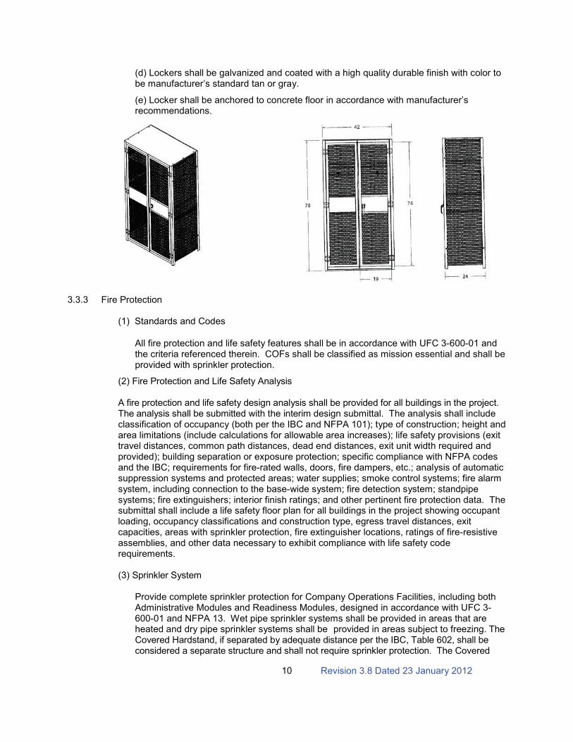
(6) TA-50 Storage Lockers. TA-50 lockers shall be provided as indicated in Paragraph 3.2.3 (3), with size and appearance similar to that shown below. TA-50 lockers shall be single tier, heavy duty, all welded ventilated type and meet the following minimum requirements:
(a) All tops, bottoms and shelves shall be constructed of minimum 16 gauge thick cold rolled sheet steel. All sides, intermediate partitions and backs shall be constructed of minimum 14 gauge flattened expanded metal or perforated metal with a minimum free area of 50%, welded to angle iron frames. Frames shall be constructed of minimum 1” X 1” X 1/8” angle iron steel. Thickness of metal and details of assembly and supports shall provide strength and stiffness.
(b) Double doors shall have a three-point three-sided cremone latch and shall be padlockable. Doors shall be hinged with minimum five knuckle heavy duty steel pin butt hinges welded to both door and locker frame – provide three hinges per single tier door.
(c) Each locker shall include: one aluminum number plate (numbered in sequential order), one full width shelf located 12” from the top with clothes hangar rod and three locker hooks mounted below.
Revision 3.8 Dated 23 January 201210
(d) Lockers shall be galvanized and coated with a high quality durable finish with color to be manufacturer’s standard tan or gray.
(e) Locker shall be anchored to concrete floor in accordance with manufacturer’s recommendations.
3.3.3 Fire Protection
(1) Standards and Codes
All fire protection and life safety features shall be in accordance with UFC 3-600-01 and the criteria referenced therein. COFs shall be classified as mission essential and shall be provided with sprinkler protection.
(2) Fire Protection and Life Safety Analysis
A fire protection and life safety design analysis shall be provided for all buildings in the project. The analysis shall be submitted with the interim design submittal. The analysis shall include classification of occupancy (both per the IBC and NFPA 101); type of construction; height and area limitations (include calculations for allowable area increases); life safety provisions (exit travel distances, common path distances, dead end distances, exit unit width required and provided); building separation or exposure protection; specific compliance with NFPA codes and the IBC; requirements for fire-rated walls, doors, fire dampers, etc.; analysis of automatic suppression systems and protected areas; water supplies; smoke control systems; fire alarm system, including connection to the base-wide system; fire detection system; standpipe systems; fire extinguishers; interior finish ratings; and other pertinent fire protection data. The submittal shall include a life safety floor plan for all buildings in the project showing occupant loading, occupancy classifications and construction type, egress travel distances, exit capacities, areas with sprinkler protection, fire extinguisher locations, ratings of fire-resistiveassemblies, and other data necessary to exhibit compliance with life safety code requirements.
(3) Sprinkler System
Provide complete sprinkler protection for Company Operations Facilities, including both Administrative Modules and Readiness Modules, designed in accordance with UFC 3-600-01 and NFPA 13. Wet pipe sprinkler systems shall be provided in areas that are heated and dry pipe sprinkler systems shall be provided in areas subject to freezing. The Covered Hardstand, if separated by adequate distance per the IBC, Table 602, shall be considered a separate structure and shall not require sprinkler protection. The Covered
Revision 3.8 Dated 23 January 201211
Hardstand, if not separated by adequate distance per the IBC, Table 602, shall be considered to be part of the COF facility and shall require sprinkler protection. The sprinkler system design shall be in accordance with UFC 3-600-01 and NFPA 13. The sprinkler hazard classifications shall be in accordance with UFC 3-600-01, NFPA 13, and other applicable criteria. Design densities, design areas and exterior hose streams shall be in accordance with UFC 3-600-01. The sprinkler systems shall be designed and all piping sized with computer generated hydraulic calculations. The exterior hose stream demand shall be included in the hydraulic calculations. A complete sprinkler system design, including sprinklers, branch lines, floor mains and risers, shall be shown on the drawings. The sprinkler system plans shall include node and pipe identification used in the hydraulic calculations. All sprinkler system drains, including main drains, test drains, and auxiliary drains, shall be routed to a 2-foot by 2-foot splash block at exterior grade.
(a) Sprinkler Service Main and Riser
The sprinkler service main shall be a dedicated line from the distribution main. Sprinkler service and domestic service shall not be combined. The sprinkler service main shall be provided with an exterior post indicator valve with tamper switch reporting to the fire alarm control panel (FACP). The ground floor entry penetration shall be sleeved per NFPA 13 requirements for seismic protection. The sprinkler entry riser shall include a double check backflow preventer, a fire department connection, and a wall hydrant for testing of backflow preventer. The sprinkler system shall include an indicating control valve for each sprinkler system riser, a flow switch reporting to the FACP, and an exterior alarm bell. All control valves shall be OS&Y gate type and shall be provided with tamper switches connected to the FACP. Facilities with multiple floors shall be provided with floor control valves for each floor. The floor control valve assembly shall be in accordance with UFC 3-600-01, Figure 4-1.
(b) Exterior Hose Stream
Exterior hose stream demand shall be in accordance with UFC 3-600-01. Exterior hose stream demand shall be included in the sprinkler system hydraulic calculations.
(c) Backflow Preventer
A double check backflow preventer shall be provided on the fire water main serving each building. This shall be located within the building. An exterior wall hydrant with dual hose connections with OS&Y valve shall be provided to allow testing of backflow preventer at design flow as required by NFPA 13.
(d) Fire Department Connection
A fire department connection shall be provided for each building with sprinkler protection. These shall be located to be directly accessible to the fire department.
(4) System Components and Hardware
Materials for the sprinkler system, fire pump system, and hose standpipe system shall be in accordance with NFPA 13 and NFPA 20.
(5) Protection of Piping Against Earthquake Damage
Sprinkler and fire pump piping systems shall be protected against damage from earthquakes. Seismic protection shall include flexible and rigid couplings, sway bracing, seismic separation assemblies where piping crosses building seismic separation joints, and

Revision 3.8 Dated 23 January 201212
other features as required by NFPA 13 for protection of piping against damage from earthquakes.
(6) Fire Water Supply
Fire flow test data is provided in Appendix D.
(7) Fire Pump
The requirement for a fire pump installation shall be determined by the Contractor based on fire flow test data from the project site and fire protection system design requirements for the project. If required a complete fire pump installation shall be provided for the facility. It shall comply with the requirements of UFC 3-600-01, NFPA 13 and NFPA 20. The Contractor shall submit fire pump design analysis and drawings in the design requirements.
(8) Fire Detection and Alarm
Refer to Paragraph 3.3.7, Electrical and Communication Systems, for requirements.
(9) Building Construction
Construction shall comply with requirements of UFC 3-600-01, the International Building Code and NFPA 101.
(a) Fire Extinguisher Cabinets and Brackets
Fire Extinguisher cabinets and brackets shall be provided when fire extinguishers are required by UFC 3-600-01 and NFPA 101. Placement of cabinets and brackets shall be in accordance with NFPA 10. Semi-recessed cabinets shall be provided in finished areas and brackets shall be provided in non-finished areas (such as utility rooms, storage rooms, shops, and vehicle bays). Fire extinguishers shall not be provided in this contract.
(b) Interior Wall and Ceiling Finishes
Interior wall and ceiling finishes and movable partitions shall conform to the requirements of UFC 3-600-01 and NFPA 101.
3.3.4 Thermal Performance
See Paragraph 5.
3.3.5 Plumbing
(1) Exterior Wall Hydrants
In addition to wall hydrants provided around perimeter of building(s), one additional freeze-proof exterior wall hydrant or wall faucet per company shall be provided at the hardstand.
(2) Domestic Hot Water System
The main water heating equipment shall be located within a mechanical room, and also located on the ground floor level only. Instantaneous water heaters are not allowed to be used for hot water serving all COF areas except Readiness Area. System storage and recovery shall be sized to deliver sufficient capacity for all showers, for a continuous duration
Revision 3.8 Dated 23 January 201213
of ninety (90) minutes. Usage diversity factor for the showers shall be one. Minimum system total storage of water heater(s) shall be 400 gallons for 1- and 2-company COFs, and 600 gallons for 3-company and larger COFs.
3.3.6 Heating, Ventilating, and Air Conditioning
(1) Administrative Areas
See Paragraph 5 for heating and cooling of administrative areas. The admin building’s HVAC system design should include flexibility in zoning to where it can address future changes in occupant densities (e.g., a platoon office suite converted to a conference room). Administrative areas shall be temperature-controlled by the DDC system. Temperature setpoint adjustment shall be accomplished via DDC System by authorized personnel.
(a) Communications and SIPRNet rooms will each be served by an independent and dedicated air-handling system. Air handling unit system(s) shall not be floor-space mounted within the actual space served. Rooms shall be maintained at 72 degrees F and 50 percent relative humidity year-round. Assume 1775 BTU per hour for the equipment heat dissipation. Contractor shall verify this load during the design stage.
(2) Readiness Areas
The readiness module shall be [mechanically ventilated and] heated [and air conditioned].Separate air side equipment (heating, ventilation and air conditioning units) shall be provided for each readiness module. Indoor design temperature for heating shall be 55 degrees F, and for cooling [the indoor design conditions shall be 80 degrees F dry bulb with a maximum 60 percent relative humidity. Whenever the indoor dry bulb temperature and/or the maximum relative humidity is exceeded, the air conditioning unit shall run, and shall continue to run until the design dry bulb temperature and the relative humidity requirements are satisfied.] [shall be 10 degrees F above outdoor 1 percent dry bulb design temperature.] The [air conditioning unit] [ventilation unit] serving the readiness area shall be capable of providing outside air quantities, in accordance with ASHRAE 62.1, for the design people load of the readiness area. [Arms vaults shall be cooled to 80 degrees F with room air to be 100% exhausted.] [Independent and dedicated packaged A/C units shall be provided for the Arms Vaults and Non-Sensitive Secure Storage Areas.] Ventilation for Arms Vaults shall be provided in accordance with ASHRAE 62.1 requirements for storage rooms. Communication rooms located in Readiness Buildings will be served by an independent and dedicated air-handling system and shall be conditioned per Administrative Areas paragraph requirements. Administrative-type areas located within the Readiness Building shall be conditioned per Paragraph 5 requirements.
(3) HVAC Controls
HVAC Controls shall be in accordance with paragraph 5.8.3. See Appendix for HVAC Controls for typical control system points schedules. These schedules identify as a minimum points to be monitored and controlled by the building automation system (BAS). See paragraph 6 for any additional installation specific points. The points schedule drawings convey a great deal of information critical to the design, installation, and subsequent performance of the control system. It includes hardware input/output information, device ranges and settings, ANSI 709.1 communication protocol data, and information about data that is to be used at the operator workstation by the Monitoring and Control software. These schedules are available as an excel spread sheet and as AutoCAD drawings on the Engineering Knowledge Online (EKO) website https://eko.usace.army.mil/fa/bas/. Point schedule of system types not addressed in the appendix shall be developed by the Contractor, and shall be sufficiently detailed to a level consistent to a similar listed system in

Revision 3.8 Dated 23 January 201214
the appendix. It is recommended that all of the guidance and instruction documents be reviewed prior to using any of the info, as the documents provide necessary and critical information to the use of the website drawings and other information.
3.3.7 Electrical and Communications
See Paragraph 6 for clarifications and additional requirements for the electrical and communication systems.
(1) Interior Electrical and Communications
(a) Electrical
1. Characteristics. Select electrical characteristics of the power system to provide a safe, efficient, and economical distribution of power, based upon the size and types of loads to be served. Use distribution and utilization voltages of the highest level that is practical for the load to be served.
2. Nonlinear Loads. The effect of nonlinear loads such as computers and other electronic devices shall be considered and accommodated as necessary. These loads generate harmonics, which can overload conventionally sized conductors or equipment and thereby cause safety hazards and premature failures. Circuits serving such devices shall be equipped with a separate neutral conductor not shared with other circuits. Panelboards and any dry type transformers shall be rated accordingly.
3. Lightning Protection System and Transient Voltage Surge Protection. Design shall be in accordance with NFPA 780 and other referenced criteria. Providetransient voltage surge protection.
4. Receptacles. Power receptacles shall be provided per NFPA 70 and in conjunction with the proposed equipment and furniture layouts. Provide power connectivity to each workstation. Power poles shall not be used. Provide duplex receptacles adjacent to each duplex (voice/data) outlet and CATV outlet.
(b) Lighting. Lighting and lighting controls shall comply with the recommendations of the Illumination Engineering Society of North America (IESNA) and the requirements of ASHRAE 90.1.
1. Interior Lighting. Interior ambient illumination shall provide a generally glare free, high quality lighting environment and conform to IESNA RP-1-04.
(c) Telecommunication
1. Telecommunications Rooms. Telecommunications Rooms shall be provided for voice and data as shown on the standard design layouts. The telecommunications rooms shall be designed in accordance with the I3A Criteria.
2. Telecommunications Outlets. Telecommunications outlets shall be provided per the I3A Technical criteria based on functional purpose of the various spaces with the facility as modified by user special operational requirements. All COF workstations\desks shall have voice and data connection capability. All conference rooms shall have voice and data connection capability (minimum four outlets). A wall telephone

Revision 3.8 Dated 23 January 201215
outlet with a single jack shall be provided in each mechanical room, electrical room, arms vault and communications room and entrances/exits in the Readiness Modules.Provide a duplex (voice/data) outlet at the desk in each of the Storage Rooms andArms Vault in the Readiness Module. Provide a duplex outlet (voice/data) for a network printer/copier in the vending area and in the storage room adjacent to each suite. Telecommunications infrastructure shall meet the Installation Information Infrastructure Architecture (I3A) criteria and ANSI/TIA/EIA requirements.
3. Cable Trays. Provide cable tray pathways through-out the facility (Admin and Readiness Modules) to support the systems required for the construction of the facility as well as user's computer networks, video integration system, telecommunication systems and other specialized electronic systems.
4. For Detached Readiness Modules, provide a separate communication room onthe mezzanine as shown with the integrated Admin Option of the floor plans. The telecommunications rooms shall be designed in accordance with the I3A criteria and ANSI/EIA/TIA-569-B. Where copper cable runs exceed 295 feet, provide additional telecommunication rooms on the mezzanine as required. The incoming telephone service (voice and data) shall be from the nearest manhole or from the main telephone communication room in the Admin Module, size the cables and conduits as per I3A criteria.
a. All copper cabling leaving one building to go to another shall be treated as OSP cable and follow OSP cable requirements as stated in section 3.5.4 of the I3A and I3MP Grounding and Bonding Guide; this includes use of protector blocks and other grounding requirements as necessary to avoid lightning issues resulting in damaging of IT equipment.
b. Option to use fiber cable via OSP cable is authorized from the main TR andwill be terminated inside the next building on a fiber distribution panel, rack, or cabinet as required, with a minimum of 6-strands.
(d) SIPRNET <REV>
1. SIPRNET for Explosive Ordnance Disposal (EOD) and Military Intelligence (MI)COFs. </REV>
a. The SIPRNET room and infrastructure shall be designed and constructed in accordance with the <REV> </REV> Technical Guide for the Integration of SIPRNET (Secret Internet Protocol Router Network) <REV> and 13A Criteria</REV>. The SIPRNET building infrastructure design and installation shall be coordinated with the local NEC. As an option, the Communication Room and the SIPRNET Room can be combined into a single room if a SIPRNET safe/container can be used. Coordinate this option with the local NEC.
b. In the NSTISSI 7003 and the Technical Guide for Integration of SIPRNET, paragraph “Protective Distribution System”, the word "shall" shall be substituted for the word "should" or “will” in this paragraph.
c. Install one SIPRNET outlet with one drop in <REV> the office of </REV>each Company Commander<REV> (CO CDR), Executive Officer (XO), 1
stSergeant
(1SG), and each Platoon Office </REV>. Install one SIPRNET outlet with <REV> two</REV> drops in each unit conference room. The SIPRNET building
Revision 3.8 Dated 23 January 201216
infrastructure shall use Category 6 UTP copper cables with red cable jacket andred outlet modules unless otherwise directed by the local NEC. Cables shall be terminated in the SPIRNET room and at the outlet in accordance with the I3A Technical criteria for data cables. <REV> </REV>
d. SIPRNET draft specifications are located in the SIPRNET Technical Implementation Criteria, version 6, dated October 2010. The surface mounted raceway shall be used instead of the surface mounted conduit unless otherwise indicated by the local NEC. <REV>
2. SIPRNET for all other COFs. Only a SIPRNET Room shall be provided for future SIPRNET connectivity. The SIPRNET room shall be designed and constructed in accordance with the Technical Guide for the Integration of SIPRNET (Secret Internet Protocol Router Network) and I3A Criteria. Connection to the main telecommunications room from the SIPRNET room shall be via a 2-inch trade size steel conduit. Provide a communications signal ground bus bar connected to the main communications room signal bus bar via a properly sized ground wire (see MIL-HDBK-419-A). Provide one dedicated standard 20-amp duplex receptacle for a future SIPRNET rack in addition to convenience receptacles in the SIPRNET room. </REV>
(e) Cable Television. CATV shall be provided in all offices, conference rooms (minimum two outlets), and one in each of the readiness areas. The cable television system shall consist of cabling, pathways, and outlets. All building CATV systems shall conform to APPLICABLE CRITERIA to include I3A Technical criteria and the UFC 3-580-01Telecommunications Bldg Cabling Systems Planning/Design.
(f) Audio/Visual Systems. Provisions (consisting of a power receptacle and conduit for signal wiring) for a Government-furnished Government-installed projector shall be provided in each conference room.
(g) Intrusion Detection System. Contractor shall install the necessary conduit, electrical power, and wiring, to support installation of an ICIDS system in each of the Arms Room and SIPRNET Room. The Government normally installs the signal devices and equipment necessary to activate the system. Contact the Physical Security Office for guidance. If a SIPRNET safe/container is used, ICIIDS may not be required for this room. Contact the Physical Security Office for guidance.
(h) Mass Notification System. A mass notification system shall be provided for each facility and throughout the complex in accordance with UFC 4-010-01. The system shall be fully compatible with and integrated with the local Installation wide Mass Notification System.
(i) Grounding. The ground counterpoise shall be provided around the building perimeter and shall be utilized for grounding incoming service, building steel, telephone service, piping, lightning protection, and internal grounding requirements. Ground straps shall be provided where required by function and will be connected to the building grounding system. Additional grounding may be provided based on project requirements. Systems shall conform to NFPA 70 National Electrical Code, NFPA 780 Lightning Protection Code, local codes, and the US Army I3A criteria.
(j) Fire Detection and Alarm
1. A fire alarm and detection system shall be provided for this facility. It shall comply with the requirements of UFC 3-600-01 and NFPA 72. The system shall be
Revision 3.8 Dated 23 January 201217
addressable and fully compatible with and integrated with the local Installation wide Fire Alarm System.
2. All initiating devices shall be connected, Class A, Style 6, to signal line circuits (SLC). All alarm appliances shall be connected to notification appliance circuits (NAC), Class A. A looped conduit system shall be provided so that if the conduit and all conductors within are severed at any point, all NAC and SLC shall remain functional.
3. Breakglass manual fire alarm stations shall not be used.
4. Over-voltage and surge protection shall be provided at the input power of all panels.
(k) Future Soldier Land Warrior System. Provide a disconnect switch (208/120V, 3 phase, 4 wire) in each of the Secure Non-Sensitive Storage Room in the Readiness Module. Size the disconnect switch(s) and the circuit breaker(s), conductors and conduit(s) from a 208 volt, 3 phase, 4 wire distribution panel to the disconnect switch(s) based on a 200 VA continuous demand load for 100 percent of the maximum personnel in each Company Readiness Area (i.e. 150 man Readiness module x 200 VA= 30,000 VA.)
3.3.8 Energy Conservation
(1) Energy Performance. The building, including the building envelope, HVAC systems, service water heating, power, and lighting systems shall be designed to achieve a non-plug load energy consumption that is at least 40% below the consumption of a baseline building meeting the minimum requirements of ANSI/ASHRAE/IESNA Standard 90.1 (see paragraph 5.9 Energy Conservation). (Note: Plug loads shall be included in building energy modeling but are subtracted in the final calculation of Energy Performance. See section “Design After Award” for additional guidance.)
(2) Required Energy Conservation Features. All items listed in the required energy conservation features table shall be provided as a minimum. Additional energy conservation features may be required to meet the above energy performance. The contractor is responsible for determining and providing additional energy conservation features to meet the energy performance requirements. Where equipment types are indicated, only minimum efficiencies apply.
(3) Compliance Documentation. The required energy conservation features shown in the table above contributes to the achievement of the above energy performance and are life cycle cost effective for a COF. Use of the required energy conservation features does not eliminate the requirement for energy analysis calculations documenting compliance. The D-Bcontractor must document compliance with the above energy performance utilizing the methodology described in ASHRAE 90.1, Appendix G as discussed in section 01 33 16Design After Award. The design analysis shall document each of the features selected to achieve the specified energy performance.
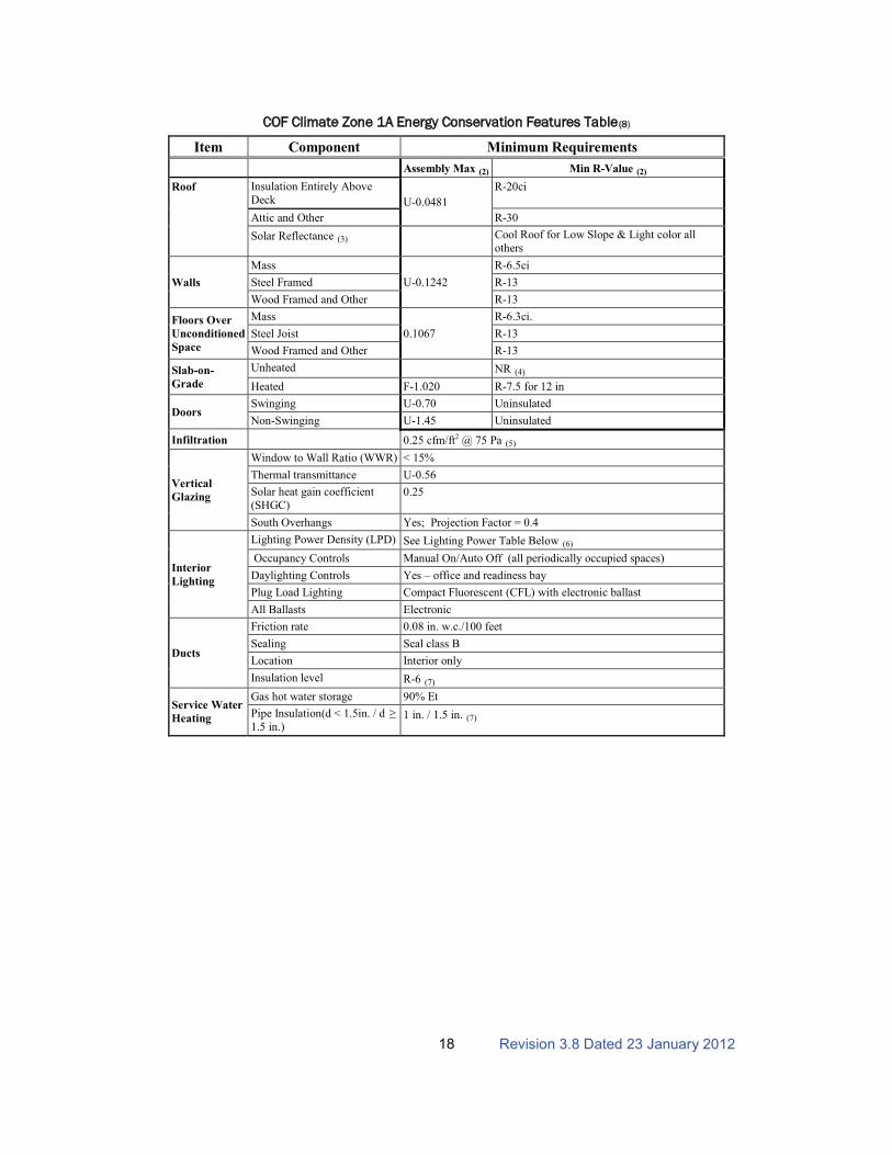
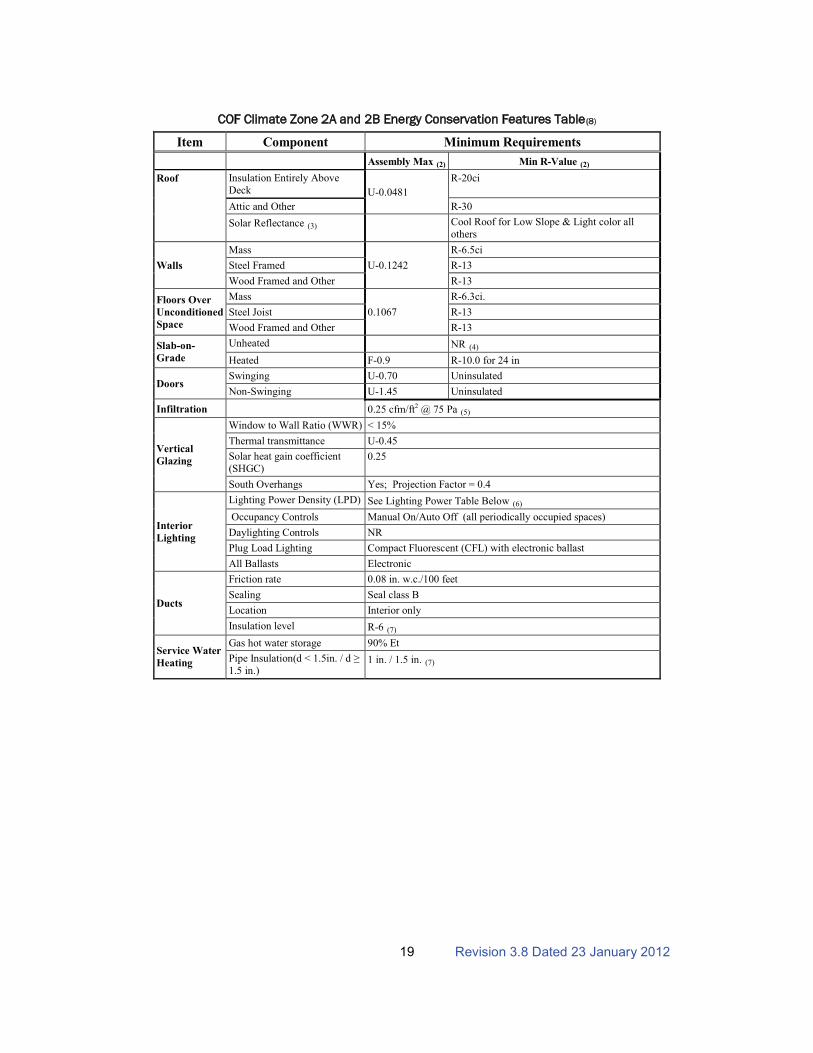
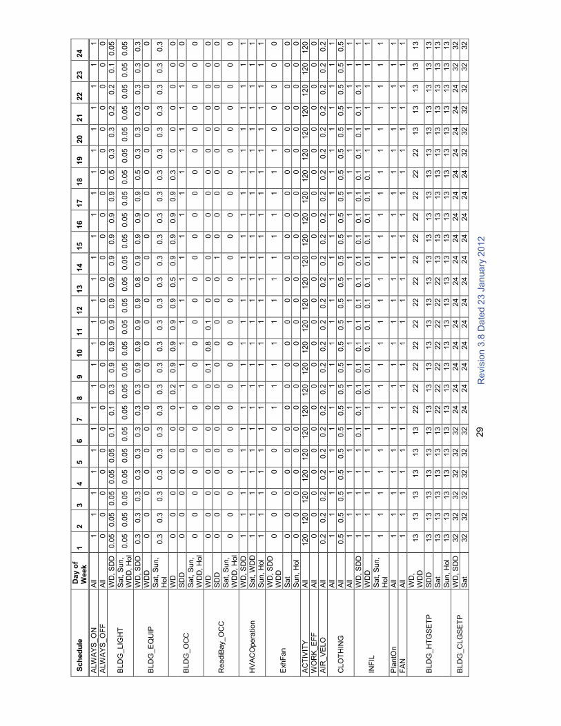
(4) Schedules. The following facility schedules must be used in all facility energy simulations for purposes of documenting compliance with energy performance requirements.
Revision 3.8 Dated 23 January 201218
COF Climate Zone 1A Energy Conservation Features Table
Item
(8)
Component Minimum Requirements
Assembly Max Min R-Value (2)
Roof
(2)
Insulation Entirely Above
Deck U-0.0481
R-20ci
Attic and Other R-30
Solar Reflectance (3) Cool Roof for Low Slope & Light color all
others
Walls
Mass
U-0.1242
R-6.5ci
Steel Framed R-13
Wood Framed and Other R-13
Floors Over
Unconditioned
Space
Mass
0.1067
R-6.3ci.
Steel Joist R-13
Wood Framed and Other R-13
Slab-on-
Grade
Unheated NR
Heated
(4)
F-1.020 R-7.5 for 12 in
DoorsSwinging U-0.70 Uninsulated
Non-Swinging U-1.45 Uninsulated
Infiltration 0.25 cfm/ft2 @ 75 Pa
Vertical
Glazing
(5)
Window to Wall Ratio (WWR) < 15%
Thermal transmittance U-0.56
Solar heat gain coefficient
(SHGC)0.25
South Overhangs Yes; Projection Factor = 0.4
Interior
Lighting
Lighting Power Density (LPD) See Lighting Power Table Below
Occupancy Controls
(6)
Manual On/Auto Off (all periodically occupied spaces)
Daylighting Controls Yes – office and readiness bay
Plug Load Lighting Compact Fluorescent (CFL) with electronic ballast
All Ballasts Electronic
Ducts
Friction rate 0.08 in. w.c./100 feet
Sealing Seal class B
Location Interior only
Insulation level R-6
Service Water
Heating
(7)
Gas hot water storage 90% Et
Pipe Insulation(d < 1.5in. / d !"
1.5 in.)1 in. / 1.5 in. (7)
Revision 3.8 Dated 23 January 201219
COF Climate Zone 2A and 2B Energy Conservation Features Table
Item
(8)
Component Minimum Requirements
Assembly Max Min R-Value (2)
Roof
(2)
Insulation Entirely Above
Deck U-0.0481
R-20ci
Attic and Other R-30
Solar Reflectance (3) Cool Roof for Low Slope & Light color all
others
Walls
Mass
U-0.1242
R-6.5ci
Steel Framed R-13
Wood Framed and Other R-13
Floors Over
Unconditioned
Space
Mass
0.1067
R-6.3ci.
Steel Joist R-13
Wood Framed and Other R-13
Slab-on-
Grade
Unheated NR
Heated
(4)
F-0.9 R-10.0 for 24 in
DoorsSwinging U-0.70 Uninsulated
Non-Swinging U-1.45 Uninsulated
Infiltration 0.25 cfm/ft2 @ 75 Pa
Vertical
Glazing
(5)
Window to Wall Ratio (WWR) < 15%
Thermal transmittance U-0.45
Solar heat gain coefficient
(SHGC)0.25
South Overhangs Yes; Projection Factor = 0.4
Interior
Lighting
Lighting Power Density (LPD) See Lighting Power Table Below
Occupancy Controls
(6)
Manual On/Auto Off (all periodically occupied spaces)
Daylighting Controls NR
Plug Load Lighting Compact Fluorescent (CFL) with electronic ballast
All Ballasts Electronic
Ducts
Friction rate 0.08 in. w.c./100 feet
Sealing Seal class B
Location Interior only
Insulation level R-6
Service Water
Heating
(7)
Gas hot water storage 90% Et
Pipe Insulation(d < 1.5in. / d !"
1.5 in.)1 in. / 1.5 in. (7)
Revision 3.8 Dated 23 January 201220
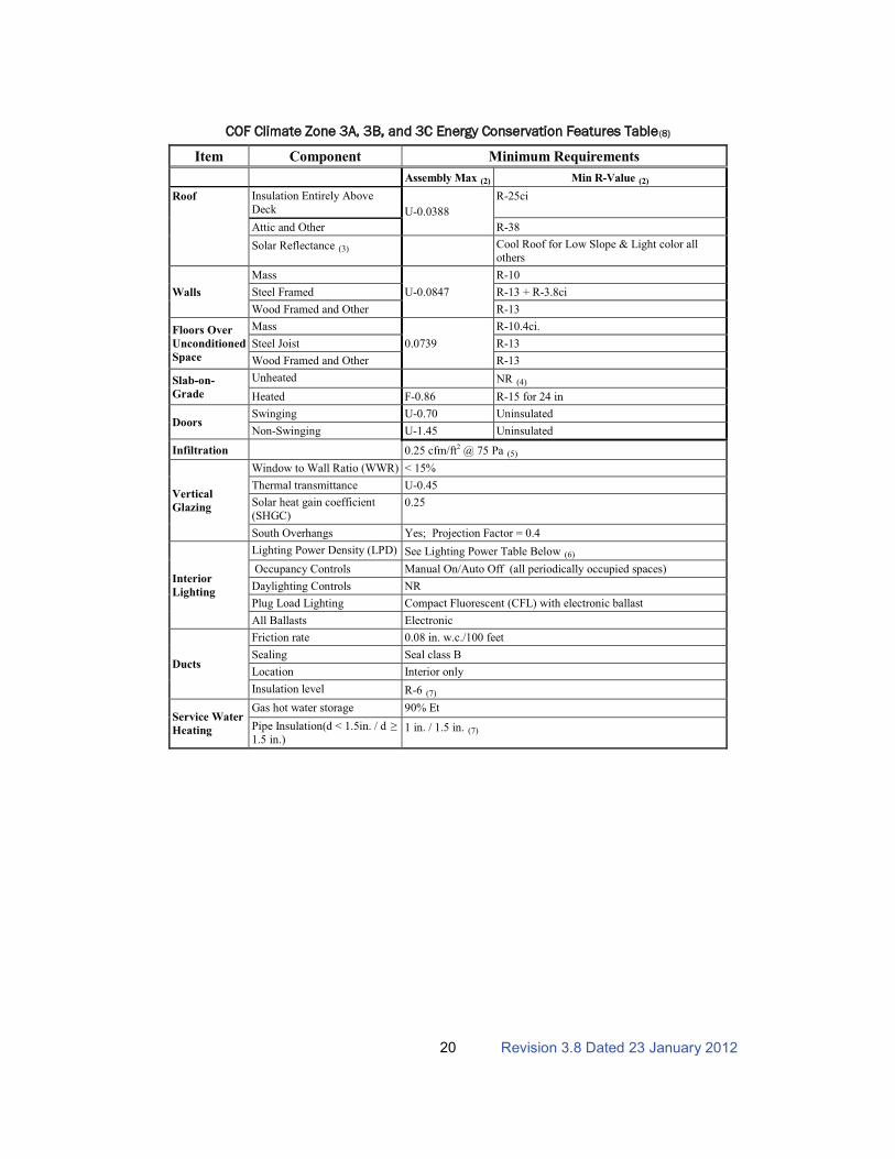
COF Climate Zone 3A, 3B, and 3C Energy Conservation Features Table
Item
(8)
Component Minimum Requirements
Assembly Max Min R-Value (2)
Roof
(2)
Insulation Entirely Above
Deck U-0.0388
R-25ci
Attic and Other R-38
Solar Reflectance (3) Cool Roof for Low Slope & Light color all
others
Walls
Mass
U-0.0847
R-10
Steel Framed R-13 + R-3.8ci
Wood Framed and Other R-13
Floors Over
Unconditioned
Space
Mass
0.0739
R-10.4ci.
Steel Joist R-13
Wood Framed and Other R-13
Slab-on-
Grade
Unheated NR
Heated
(4)
F-0.86 R-15 for 24 in
DoorsSwinging U-0.70 Uninsulated
Non-Swinging U-1.45 Uninsulated
Infiltration 0.25 cfm/ft2 @ 75 Pa
Vertical
Glazing
(5)
Window to Wall Ratio (WWR) < 15%
Thermal transmittance U-0.45
Solar heat gain coefficient
(SHGC)0.25
South Overhangs Yes; Projection Factor = 0.4
Interior
Lighting
Lighting Power Density (LPD) See Lighting Power Table Below
Occupancy Controls
(6)
Manual On/Auto Off (all periodically occupied spaces)
Daylighting Controls NR
Plug Load Lighting Compact Fluorescent (CFL) with electronic ballast
All Ballasts Electronic
Ducts
Friction rate 0.08 in. w.c./100 feet
Sealing Seal class B
Location Interior only
Insulation level R-6
Service Water
Heating
(7)
Gas hot water storage 90% Et
Pipe Insulation(d < 1.5in. / d !"
1.5 in.)1 in. / 1.5 in. (7)

Revision 3.8 Dated 23 January 201221
COF Climate Zone 4A, 4B, and 4C Energy Conservation Features Table
Item
(8)
Component Minimum Requirements
Assembly Max Min R-Value (2)
Roof
(2)
Insulation Entirely Above
Deck U-0.0388
R-25ci
Attic and Other R-38
Solar Reflectance (3) Cool Roof for Low Slope & Light color all
others
Walls
Mass
U-0.0676
R-13
Steel Framed R-13 + R-7.5ci
Wood Framed and Other R-13 + R-3.8ci
Floors Over
Unconditioned
Space
Mass
0.0739
R-10.4ci.
Steel Joist R-13
Wood Framed and Other R-13
Slab-on-
Grade
Unheated F-0.520 R-15.0 for 24 in.
Heated F-0.843 R-20.0 for 24 in.
DoorsSwinging U-0.50 Insulated
Non-Swinging U-0.50 Insulated
Infiltration 0.25 cfm/ft2 @ 75 Pa
Vertical
Glazing
(5)
Window to Wall Ratio (WWR) < 15%
Thermal transmittance U-0.42
Solar heat gain coefficient
(SHGC)0.39
South Overhangs Yes; Projection Factor = 0.4
Interior
Lighting
Lighting Power Density (LPD) See Lighting Power Table Below
Occupancy Controls
(6)
Manual On/Auto Off (all periodically occupied spaces)
Daylighting Controls NR
Plug Load Lighting Compact Fluorescent (CFL) with electronic ballast
All Ballasts Electronic
Ducts
Friction rate 0.08 in. w.c./100 feet
Sealing Seal class B
Location Interior only
Insulation level R-6
Service Water
Heating
(7)
Gas hot water storage 90% Et
Pipe Insulation(d < 1.5in. / d !"
1.5 in.)1 in. / 1.5 in. (7)
Revision 3.8 Dated 23 January 201222
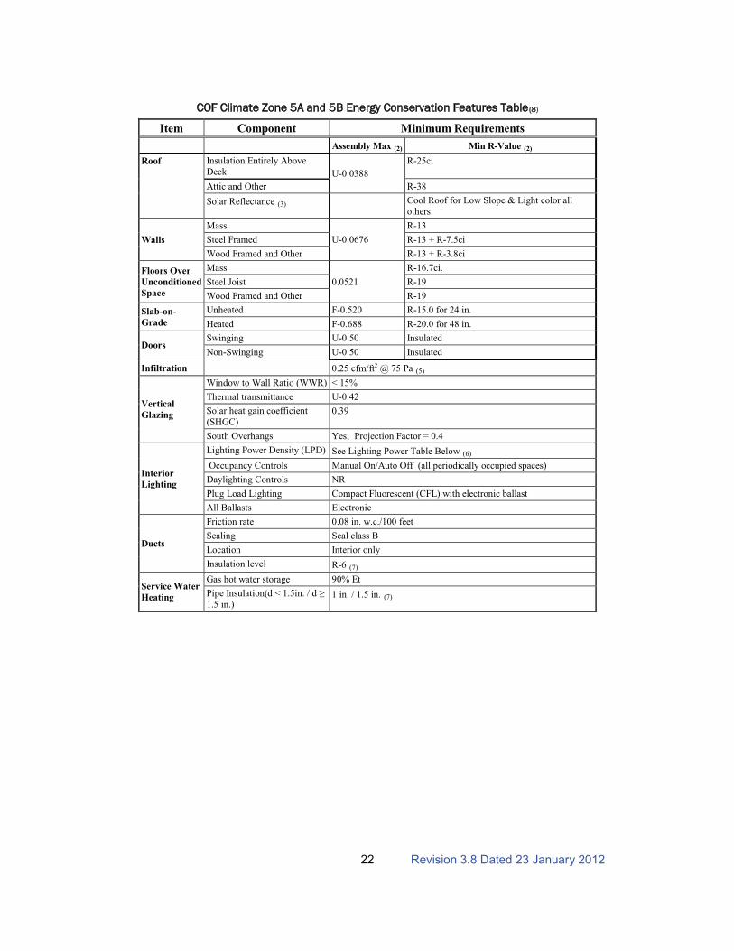
COF Climate Zone 5A and 5B Energy Conservation Features Table
Item
(8)
Component Minimum Requirements
Assembly Max Min R-Value (2)
Roof
(2)
Insulation Entirely Above
Deck U-0.0388
R-25ci
Attic and Other R-38
Solar Reflectance (3) Cool Roof for Low Slope & Light color all
others
Walls
Mass
U-0.0676
R-13
Steel Framed R-13 + R-7.5ci
Wood Framed and Other R-13 + R-3.8ci
Floors Over
Unconditioned
Space
Mass
0.0521
R-16.7ci.
Steel Joist R-19
Wood Framed and Other R-19
Slab-on-
Grade
Unheated F-0.520 R-15.0 for 24 in.
Heated F-0.688 R-20.0 for 48 in.
DoorsSwinging U-0.50 Insulated
Non-Swinging U-0.50 Insulated
Infiltration 0.25 cfm/ft2 @ 75 Pa
Vertical
Glazing
(5)
Window to Wall Ratio (WWR) < 15%
Thermal transmittance U-0.42
Solar heat gain coefficient
(SHGC)0.39
South Overhangs Yes; Projection Factor = 0.4
Interior
Lighting
Lighting Power Density (LPD) See Lighting Power Table Below
Occupancy Controls
(6)
Manual On/Auto Off (all periodically occupied spaces)
Daylighting Controls NR
Plug Load Lighting Compact Fluorescent (CFL) with electronic ballast
All Ballasts Electronic
Ducts
Friction rate 0.08 in. w.c./100 feet
Sealing Seal class B
Location Interior only
Insulation level R-6
Service Water
Heating
(7)
Gas hot water storage 90% Et
Pipe Insulation(d < 1.5in. / d !"
1.5 in.)1 in. / 1.5 in. (7)

Revision 3.8 Dated 23 January 201223
COF Climate Zone 6A and 6B Energy Conservation Features Table
Item
(8)
Component Minimum Requirements
Assembly Max Min R-Value (2)
Roof
(2)
Insulation Entirely Above
Deck U-0.0388
R-25ci
Attic and Other R-38
Solar Reflectance (3) NR
Walls
(4)
Mass
U-0.0676
R-13
Steel Framed R-13 + R-7.5ci
Wood Framed and Other R-13 + R-3.8ci
Floors Over
Unconditioned
Space
Mass
0.0377
R-25.1ci.
Steel Joist R-30
Wood Framed and Other R-30
Slab-on-
Grade
Unheated F-0.510 R-20.0 for 24 in.
Heated F-0.688 R-20.0 for 48 in.
DoorsSwinging U-0.50 Insulated
Non-Swinging U-0.50 Insulated
Infiltration 0.25 cfm/ft2 @ 75 Pa
Vertical
Glazing
(5)
Window to Wall Ratio (WWR) < 15%
Thermal transmittance U-0.42
Solar heat gain coefficient
(SHGC)0.39
South Overhangs Yes; Projection Factor = 0.4
Interior
Lighting
Lighting Power Density (LPD) See Lighting Power Table Below
Occupancy Controls
(6)
Manual On/Auto Off (all periodically occupied spaces)
Daylighting Controls NR
Plug Load Lighting Compact Fluorescent (CFL) with electronic ballast
All Ballasts Electronic
Ducts
Friction rate 0.08 in. w.c./100 feet
Sealing Seal class B
Location Interior only
Insulation level R-6
Service Water
Heating
(7)
Gas hot water storage 90% Et
Pipe Insulation(d < 1.5in. / d !"
1.5 in.)1 in. / 1.5 in. (7)
Revision 3.8 Dated 23 January 201224
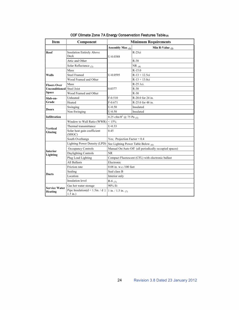
COF Climate Zone 7A Energy Conservation Features Table
Item
(8)
Component Minimum Requirements
Assembly Max Min R-Value (2)
Roof
(2)
Insulation Entirely Above
Deck U-0.0388
R-25ci
Attic and Other R-38
Solar Reflectance (3) NR
Walls
(4)
Mass
U-0.0595
R-15.0
Steel Framed R-13 + 12.5ci
Wood Framed and Other R-13 + 13.0ci
Floors Over
Unconditioned
Space
Mass
0.0377
R-25.1ci.
Steel Joist R-30
Wood Framed and Other R-30
Slab-on-
Grade
Unheated F-0.510 R-20.0 for 24 in.
Heated F-0.671 R-25.0 for 48 in.
DoorsSwinging U-0.50 Insulated
Non-Swinging U-0.50 Insulated
Infiltration 0.25 cfm/ft2 @ 75 Pa
Vertical
Glazing
(5)
Window to Wall Ratio (WWR) < 15%
Thermal transmittance U-0.33
Solar heat gain coefficient
(SHGC)0.45
South Overhangs Yes; Projection Factor = 0.4
Interior
Lighting
Lighting Power Density (LPD) See Lighting Power Table Below
Occupancy Controls
(6)
Manual On/Auto Off (all periodically occupied spaces)
Daylighting Controls NR
Plug Load Lighting Compact Fluorescent (CFL) with electronic ballast
All Ballasts Electronic
Ducts
Friction rate 0.08 in. w.c./100 feet
Sealing Seal class B
Location Interior only
Insulation level R-6
Service Water
Heating
(7)
Gas hot water storage 90% Et
Pipe Insulation(d < 1.5in. / d !"
1.5 in.)1 in. / 1.5 in. (7)

Revision 3.8 Dated 23 January 201225
COF Climate Zone 8A Energy Conservation Features Table
Item
(8)
Component Minimum Requirements
Assembly Max Min R-Value (2)
Roof
(2)
Insulation Entirely Above
Deck U-0.0325
R-30ci
Attic and Other R-49
Solar Reflectance (3) NR
Walls
(4)
Mass
U-0.0391
R-11.4 + R-3.0ci
Steel Framed R-13 + 18.8ci
Wood Framed and Other R-13 + 19.5ci
Floors Over
Unconditioned
Space
Mass
0.0377
R-25.1ci.
Steel Joist R-30
Wood Framed and Other R-30
Slab-on-
Grade
Unheated F-0.434 R-20.0 for 48 in.
Heated F-0.671 R-25.0 for 48 in.
DoorsSwinging U-0.50 Insulated
Non-Swinging U-0.50 Insulated
Infiltration 0.25 cfm/ft2 @ 75 Pa
Vertical
Glazing
(5)
Window to Wall Ratio (WWR) < 15%
Thermal transmittance U-0.33
Solar heat gain coefficient
(SHGC)NR
South Overhangs NR
Interior
Lighting
Lighting Power Density (LPD) See Lighting Power Table Below
Occupancy Controls
(6)
Manual On/Auto Off (all periodically occupied spaces)
Daylighting Controls NR
Plug Load Lighting Compact Fluorescent (CFL) with electronic ballast
All Ballasts Electronic
Ducts
Friction rate 0.08 in. w.c./100 feet
Sealing Seal class B
Location Interior only
Insulation level R-8
Service Water
Heating
(7)
Gas hot water storage 90% Et
Pipe Insulation(d < 1.5in. / d !"
1.5 in.)1 in. / 1.5 in. (7)

Revision 3.8 Dated 23 January 201226
Notes:
1. Omitted.
2. U-values and R-values for assemblies and their definitions, requirements, and determinations can
be found in ANSI/ASHRAE/IESNA Standard 90.1.
3. Light colored and cool roofs: reflect and emit the sun's heat back to the sky instead of transferring
it to the building below. "Coolness" is measured by two properties, solar reflectance and thermal
emittance. Both properties are measured from 0 to 1 and the higher the value, the "cooler" the roof.
A high reflectance keeps much of the sun’s energy from being absorbed, while a high thermal
emittance radiates away any solar energy that is absorbed, allowing the roof to cool more rapidly.
Cool roofs are typically white and have a smooth surface. Commercial roof products that qualify as
cool roofs fall into three categories: single-ply, liquid-applied, and metal panels. The solar reflectance
and thermal emittance property values represent initial conditions as determined by a laboratory
accredited by the Cool Roof Rating Council.
Cool roofs are cost effective over air-conditioned spaces for buildings located in climate zones 1 - 5. In these locations, a minimum of 75% of the entire roof surface not used for roof penetrations shall be covered with roofing products that comply with one or more of the following:
! Have a minimum initial SRI of 78 for a low-sloped roof (a slope less than or equal to 2:12)
and a minimum initial SRI of 29 for a steep-sloped roof (a slope of more than 2:12).
! Comply with the criteria for the US EPA’s Energy Star Program Requirements for Roof
Products – Eligibility Criteria. For industrial buildings with only heating and ventilation, cool roofs can improve the comfort conditions (and hence productivity) in the space.
In order to be considered a cool roof, a solar reflectance of 0.67 when tested in accordance with ASTM C1549, ASTM E903, or ASTM E1918 and, in addition, a minimum thermal emittance of 0.75 when tested in accordance with ASTM C1371 or ASTM E408, or a minimum Solar Reflective Index of 78 when determined in accordance with the Solar Reflectance Index method in ASTM E1980 where standard white is SRI = 100 and standard black has SRI = 0. An SRI can be determined by the following equations:
SRI = 123.97 – 141.35(x) + 9.655(x2
where)
0.125205.9
603.0797.20
"#
#$#%
&
&'x ,
Where ' is the solar absorptance (= 1 – solar reflectance) and & is the thermal emissivity, which were derived from ASTM E1980 assuming a medium wind speed.
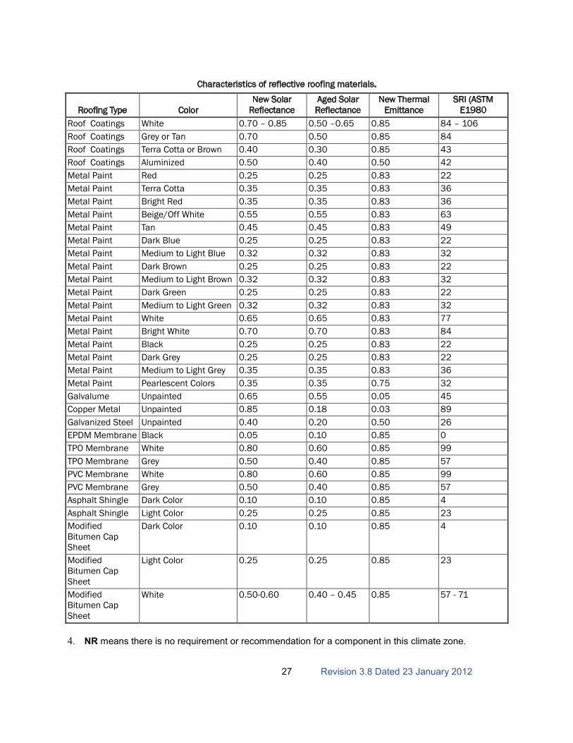
The limited color choices available for cool roofs may not be acceptable to the installation. When this conflict cannot be resolved, the designer shall use the highest reflectance available in the roofing type/color acceptable to the installation.
Revision 3.8 Dated 23 January 201227
Characteristics of reflective roofing materials.
Roofing Type Color New Solar
Reflectance Aged Solar Reflectance
New Thermal Emittance
SRI (ASTM E1980
Roof Coatings White 0.70 – 0.85 0.50 –0.65 0.85 84 – 106
Roof Coatings Grey or Tan 0.70 0.50 0.85 84
Roof Coatings Terra Cotta or Brown 0.40 0.30 0.85 43
Roof Coatings Aluminized 0.50 0.40 0.50 42
Metal Paint Red 0.25 0.25 0.83 22
Metal Paint Terra Cotta 0.35 0.35 0.83 36
Metal Paint Bright Red 0.35 0.35 0.83 36
Metal Paint Beige/Off White 0.55 0.55 0.83 63
Metal Paint Tan 0.45 0.45 0.83 49
Metal Paint Dark Blue 0.25 0.25 0.83 22
Metal Paint Medium to Light Blue 0.32 0.32 0.83 32
Metal Paint Dark Brown 0.25 0.25 0.83 22
Metal Paint Medium to Light Brown 0.32 0.32 0.83 32
Metal Paint Dark Green 0.25 0.25 0.83 22
Metal Paint Medium to Light Green 0.32 0.32 0.83 32
Metal Paint White 0.65 0.65 0.83 77
Metal Paint Bright White 0.70 0.70 0.83 84
Metal Paint Black 0.25 0.25 0.83 22
Metal Paint Dark Grey 0.25 0.25 0.83 22
Metal Paint Medium to Light Grey 0.35 0.35 0.83 36
Metal Paint Pearlescent Colors 0.35 0.35 0.75 32
Galvalume Unpainted 0.65 0.55 0.05 45
Copper Metal Unpainted 0.85 0.18 0.03 89
Galvanized Steel Unpainted 0.40 0.20 0.50 26
EPDM Membrane Black 0.05 0.10 0.85 0
TPO Membrane White 0.80 0.60 0.85 99
TPO Membrane Grey 0.50 0.40 0.85 57
PVC Membrane White 0.80 0.60 0.85 99
PVC Membrane Grey 0.50 0.40 0.85 57
Asphalt Shingle Dark Color 0.10 0.10 0.85 4
Asphalt Shingle Light Color 0.25 0.25 0.85 23
Modified Bitumen Cap Sheet
Dark Color 0.10 0.10 0.85 4
Modified Bitumen Cap Sheet
Light Color 0.25 0.25 0.85 23
Modified Bitumen Cap Sheet
White 0.50-0.60 0.40 – 0.45 0.85 57 - 71
4. NR means there is no requirement or recommendation for a component in this climate zone.
Revision 3.8 Dated 23 January 201228
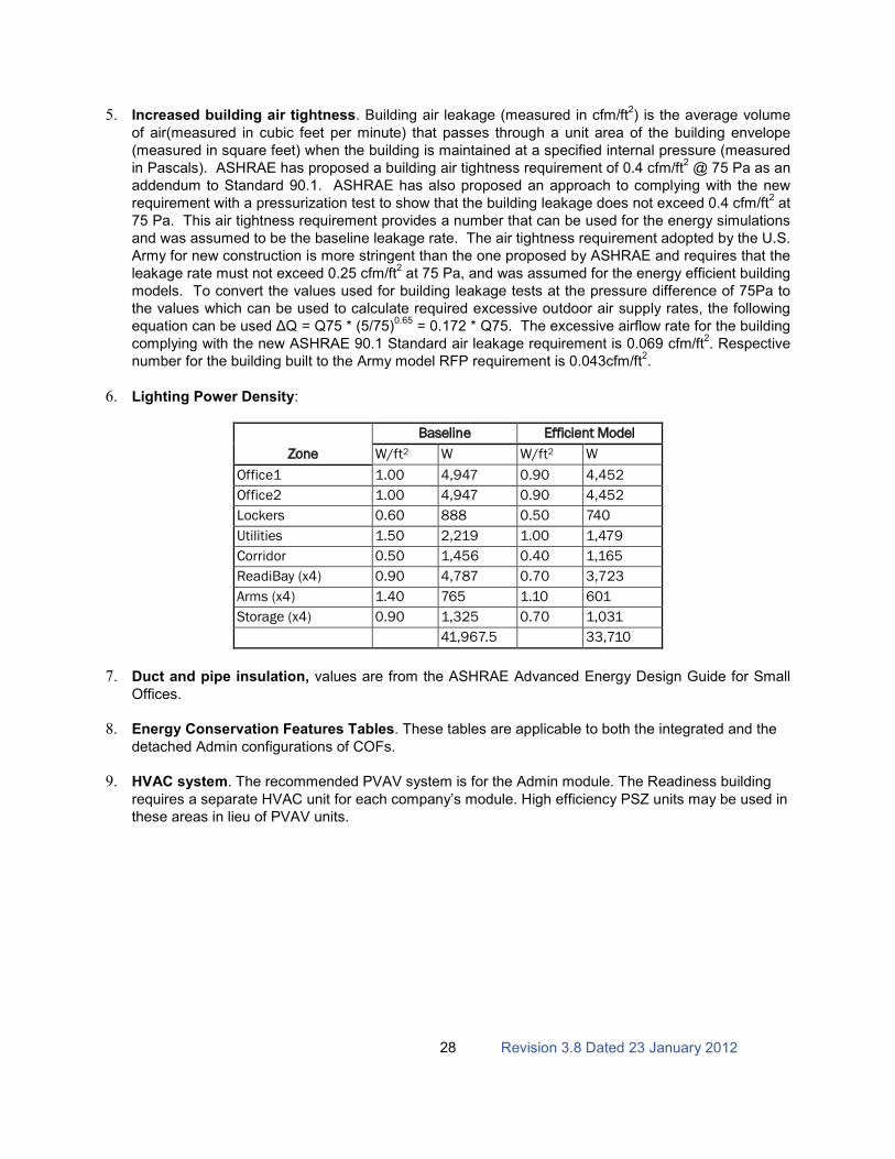
5. Increased building air tightness. Building air leakage (measured in cfm/ft2) is the average volume
of air(measured in cubic feet per minute) that passes through a unit area of the building envelope
(measured in square feet) when the building is maintained at a specified internal pressure (measured
in Pascals). ASHRAE has proposed a building air tightness requirement of 0.4 cfm/ft2
@ 75 Pa as an
addendum to Standard 90.1. ASHRAE has also proposed an approach to complying with the new
requirement with a pressurization test to show that the building leakage does not exceed 0.4 cfm/ft2
at
75 Pa. This air tightness requirement provides a number that can be used for the energy simulations
and was assumed to be the baseline leakage rate. The air tightness requirement adopted by the U.S.
Army for new construction is more stringent than the one proposed by ASHRAE and requires that the
leakage rate must not exceed 0.25 cfm/ft2
at 75 Pa, and was assumed for the energy efficient building
models. To convert the values used for building leakage tests at the pressure difference of 75Pa to
the values which can be used to calculate required excessive outdoor air supply rates, the following
!"#$%&'()*$()+!)#,!-)./)0)/12)3)4251260.65
= 0.172 * Q75. The excessive airflow rate for the building
complying with the new ASHRAE 90.1 Standard air leakage requirement is 0.069 cfm/ft2. Respective
number for the building built to the Army model RFP requirement is 0.043cfm/ft2.
6. Lighting Power Density:
Zone
Baseline Efficient Model
W/ft W 2 W/ft W 2
Office1 1.00 4,947 0.90 4,452
Office2 1.00 4,947 0.90 4,452
Lockers 0.60 888 0.50 740
Utilities 1.50 2,219 1.00 1,479
Corridor 0.50 1,456 0.40 1,165
ReadiBay (x4) 0.90 4,787 0.70 3,723
Arms (x4) 1.40 765 1.10 601
Storage (x4) 0.90 1,325 0.70 1,031
41,967.5 33,710
7. Duct and pipe insulation, values are from the ASHRAE Advanced Energy Design Guide for Small
Offices.
8. Energy Conservation Features Tables. These tables are applicable to both the integrated and the
detached Admin configurations of COFs.
9. HVAC system. The recommended PVAV system is for the Admin module. The Readiness building
requires a separate HVAC unit for each company’s module. High efficiency PSZ units may be used in
these areas in lieu of PVAV units.
R
evis
ion
3.8
Da
ted 2
3 J
an
uary
20
12
29
Sch
ed
ule
Da
y o
f W
eek
12
34
56
78
910
11
12
13
14
15
16
17
18
19
20
21
22
23
24
ALW
AY
S_O
NA
ll1
11
11
11
11
11
11
11
11
11
11
11
1
ALW
AY
S_O
FF
All
00
00
00
00
00
00
00
00
00
00
00
00
BLD
G_LIG
HT
WD
, S
DD
0.0
50.0
50.0
50.0
50.0
50.1
0.1
0.3
0.9
0.9
0.9
0.9
0.9
0.9
0.9
0.9
0.9
0.5
0.3
0.3
0.2
0.2
0.1
0.0
5
Sat, S
un,
WD
D, H
ol
0.0
50.0
50.0
50.0
50.0
50.0
50.0
50.0
50.0
50.0
50.0
50.0
50.0
50.0
50.0
50.0
50.0
50.0
50.0
50.0
50.0
50.0
50.0
50.0
5
BLD
G_E
QU
IP
WD
, S
DD
0.3
0.3
0.3
0.3
0.3
0.3
0.3
0.3
0.9
0.9
0.9
0.9
0.8
0.9
0.9
0.9
0.9
0.5
0.3
0.3
0.3
0.3
0.3
0.3
WD
D0
00
00
00
00
00
00
00
00
00
00
00
0
Sat, S
un,
Hol
0.3
0.3
0.3
0.3
0.3
0.3
0.3
0.3
0.3
0.3
0.3
0.3
0.3
0.3
0.3
0.3
0.3
0.3
0.3
0.3
0.3
0.3
0.3
0.3
BLD
G_O
CC
WD
00
00
00
00.2
0.9
0.9
0.9
0.9
0.5
0.9
0.9
0.9
0.9
0.3
00
00
00
SD
D0
00
00
01
11
11
11
11
11
11
11
10
0
Sat, S
un,
WD
D, H
ol
00
00
00
00
00
00
00
00
00
00
00
00
ReadiB
ay_O
CC
WD
00
00
00
00
0.1
0.8
0.1
00
00
00
00
00
00
0
SD
D0
00
00
00
00
00
00
10
00
00
00
00
0
Sat, S
un,
WD
D, H
ol
00
00
00
00
00
00
00
00
00
00
00
00
HV
AC
Opera
tion
WD
, S
DD
11
11
11
11
11
11
11
11
11
11
11
11
Sat, W
DD
11
11
11
11
11
11
11
11
11
11
11
11
Sun,
Hol
11
11
11
11
11
11
11
11
11
11
11
11
ExhF
an
WD
, S
DD
W
DD
00
00
00
11
11
11
11
11
11
10
00
00
Sat
00
00
00
00
00
00
00
00
00
00
00
00
Sun,
Hol
00
00
00
00
00
00
00
00
00
00
00
00
AC
TIV
ITY
All
120
120
120
120
120
120
120
120
120
120
120
120
120
120
120
120
120
120
120
120
120
120
120
120
WO
RK
_E
FF
All
00
00
00
00
00
00
00
00
00
00
00
00
AIR
_V
ELO
All
0.2
0.2
0.2
0.2
0.2
0.2
0.2
0.2
0.2
0.2
0.2
0.2
0.2
0.2
0.2
0.2
0.2
0.2
0.2
0.2
0.2
0.2
0.2
0.2
CLO
TH
ING
All
11
11
11
11
11
11
11
11
11
11
11
11
All
0.5
0.5
0.5
0.5
0.5
0.5
0.5
0.5
0.5
0.5
0.5
0.5
0.5
0.5
0.5
0.5
0.5
0.5
0.5
0.5
0.5
0.5
0.5
0.5
All
11
11
11
11
11
11
11
11
11
11
11
11
INF
IL
WD
, S
DD
11
11
10.1
0.1
0.1
0.1
0.1
0.1
0.1
0.1
0.1
0.1
0.1
0.1
0.1
0.1
0.1
0.1
0.1
11
WD
D1
11
11
11
0.1
0.1
0.1
0.1
0.1
0.1
0.1
0.1
0.1
0.1
0.1
11
11
11
Sat, S
un,
Hol
11
11
11
11
11
11
11
11
11
11
11
11
Pla
ntO
nA
ll1
11
11
11
11
11
11
11
11
11
11
11
1
FA
NA
ll1
11
11
11
11
11
11
11
11
11
11
11
1
BLD
G_H
TG
SE
TP
WD
, W
DD
13
13
13
13
13
13
22
22
22
22
22
22
22
22
22
22
22
22
22
13
13
13
13
13
SD
D13
13
13
13
13
13
13
13
13
13
13
13
13
13
13
13
13
13
13
13
13
13
13
13
Sat
13
13
13
13
13
13
22
22
22
22
22
22
22
13
13
13
13
13
13
13
13
13
13
13
Sun,
Hol
13
13
13
13
13
13
13
13
13
13
13
13
13
13
13
13
13
13
13
13
13
13
13
13
BLD
G_C
LG
SE
TP
WD
, S
DD
32
32
32
32
32
32
24
24
24
24
24
24
24
24
24
24
24
24
24
24
24
24
32
32
Sat
32
32
32
32
32
32
24
24
24
24
24
24
24
24
24
24
24
24
32
32
32
32
32
32
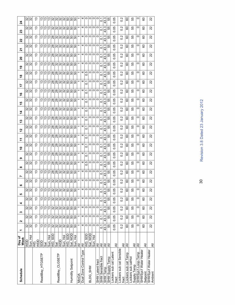
R
evis
ion
3.8
Da
ted 2
3 J
an
uary
20
12
30
Sch
ed
ule
Da
y o
f W
eek
12
34
56
78
910
11
12
13
14
15
16
17
18
19
20
21
22
23
24
WD
D32
32
32
32
32
32
32
32
32
32
32
32
32
32
32
32
32
32
32
32
32
32
32
32
Sun,
Hol
32
32
32
32
32
32
32
32
32
32
32
32
32
32
32
32
32
32
32
32
32
32
32
32
ReadiB
ay_H
TG
SE
TP
WD
, W
DD
13
13
13
13
13
13
13
13
13
13
13
13
13
13
13
13
13
13
13
13
13
13
13
13
SD
D13
13
13
13
13
13
13
13
13
13
13
13
13
13
13
13
13
13
13
13
13
13
13
13
Sat
13
13
13
13
13
13
13
13
13
13
13
13
13
13
13
13
13
13
13
13
13
13
13
13
Sun,
Hol
13
13
13
13
13
13
13
13
13
13
13
13
13
13
13
13
13
13
13
13
13
13
13
13
ReadiB
ay_C
LG
SE
TP
WD
, S
DD
32
32
32
32
32
32
28
28
28
28
28
28
28
28
28
28
28
28
28
28
28
28
32
32
Sat
32
32
32
32
32
32
28
28
28
28
28
28
28
28
28
28
28
28
32
32
32
32
32
32
WD
D32
32
32
32
32
32
32
32
32
32
32
32
32
32
32
32
32
32
32
32
32
32
32
32
Sun,
Hol
32
32
32
32
32
32
32
32
32
32
32
32
32
32
32
32
32
32
32
32
32
32
32
32
Hum
idity S
etp
oin
t
WD
, S
DD
50
50
50
50
50
50
50
50
50
50
50
50
50
50
50
50
50
50
50
50
50
50
50
50
Sat, W
DD
50
50
50
50
50
50
50
50
50
50
50
50
50
50
50
50
50
50
50
50
50
50
50
50
Sun,
Hol
50
50
50
50
50
50
50
50
50
50
50
50
50
50
50
50
50
50
50
50
50
50
50
50
Min
OA
All
11
11
11
11
11
11
11
11
11
11
11
11
Dual Z
one C
ontr
ol T
ype
All
44
44
44
44
44
44
44
44
44
44
44
44
BLD
G_S
HW
WD
, S
DD
00
00
00
00.5
0.1
0.1
0.1
0.1
0.1
0.1
0.1
0.1
0.1
0.5
00
00
00
Sat, W
DD
00
00
00
00
00
00
00
00
00
00
00
00
Sun,
Hol
00
00
00
00
00
00
00
00
00
00
00
00
SH
W L
ate
nt fr
act
All
00
00
00
00
00
00
00
00
00
00
00
00
SH
W S
ensib
le f
ract
All
0.1
0.1
0.1
0.1
0.1
0.1
0.1
0.1
0.1
0.1
0.1
0.1
0.1
0.1
0.1
0.1
0.1
0.1
0.1
0.1
0.1
0.1
0.1
0.1
SH
W T
em
p
All
43.3
43.3
43.3
43.3
43.3
43.3
43.3
43.3
43.3
43.3
43.3
43.3
43.3
43.3
43.3
43.3
43.3
43.3
43.3
43.3
43.3
43.3
43.3
43.3
SH
W S
upply
Tem
p
All
55
55
55
55
55
55
55
55
55
55
55
55
55
55
55
55
55
55
55
55
55
55
55
55
Lockers
sub c
at Late
nt
fract
All
0.0
50.0
50.0
50.0
50.0
50.0
50.0
50.0
50.0
50.0
50.0
50.0
50.0
50.0
50.0
50.0
50.0
50.0
50.0
50.0
50.0
50.0
50.0
50.0
5
Lockers
sub c
at S
ensib
le
fract
All
0.2
0.2
0.2
0.2
0.2
0.2
0.2
0.2
0.2
0.2
0.2
0.2
0.2
0.2
0.2
0.2
0.2
0.2
0.2
0.2
0.2
0.2
0.2
0.2
Lockers
sub c
at T
em
p
All
60
60
60
60
60
60
60
60
60
60
60
60
60
60
60
60
60
60
60
60
60
60
60
60
Lockers
sub c
atH
ot
Supply
Tem
p
All
55
55
55
55
55
55
55
55
55
55
55
55
55
55
55
55
55
55
55
55
55
55
55
55
SH
WS
ys1-L
oop-T
em
pA
ll0
00
00
00
00
00
00
00
00
00
00
00
0
SH
WS
ys1 W
ate
r H
eate
r S
etp
oin
t A
ll60
60
60
60
60
60
60
60
60
60
60
60
60
60
60
60
60
60
60
60
60
60
60
60
SH
WS
ys1 W
ate
r H
eate
r A
mbie
nt
All
22
22
22
22
22
22
22
22
22
22
22
22
22
22
22
22
22
22
22
22
22
22
22
22

Revision 3.8 Dated 23 January 2012
31
3.3.9 Furniture Systems
The following criterion describes the furnishing requirements for all room types. Furnishings, other than installed equipment, are to be Government-furnished and Government-installed (GFGI) unless otherwise specified in this document. The following furnishings list is provided for coordination of room and office layouts to ensure suitability for their intended function.
Table 1: Room Size and Furnishings Chart
Table 1- Room Size and Furnishings Chart
Room Description NSF Comments Furniture Required
CO Commander 150 PRIVATE OFFICE
U-shaped executive 36” D wood desk unit consisting of: single pedestal desk w/ one box, box, file pedestal ; bridge unit; hutch w/ doors and task light; credenza unit with two drawer lateral file; two wood side chairs; one ergonomic executive task chair. Note: one cable grommet per work surface.
XO Executive Officer 150 PRIVATE OFFICE
L-shaped 30” D wood desk unit consisting of: single pedestal desk w/one box, box, file pedestal; return w/file, file pedestal; hutch w/doors and task light;, one 4-drawer lateral file, two wood guest chairs, one ergonomic task chair. Note: one cable grommet per work surface.
1SG 1st
150Sergeant PRIVATE OFFICE
L-shaped 30” D wood desk unit consisting of: single pedestal desk w/one box, box, file pedestal; return w/file, file pedestal; hutch w/doors and task light;, one 4-drawer lateral file, two wood guest chairs, one ergonomic executive task chair. Note: one cable grommet per work surface.
TRAINING Training Room 150 PRIVATE OFFICE
Two L-shaped metal desk units consisting of: double pedestal desk w/ two pedestals, one box, box, file and one file, file configuration; overhead storage unit w/ doors and task light, two 4-drawer lateral files, two guest chairs, one ergonomic task chair. Note; one grommet per work surface
PLATOON Platoon Offices 150x4 SEMI-PRIVATE OFFICES
For each 150 SF office, 2 single pedestal metal desks with overhead storage unit with doors; 2 ergonomic task chairs, 2 bookcases for manuals, two 4-drawer file cabinets. Note: one grommet on work surface.
CONF. ROOM
Conference Room Varies CONFERENCE ROOMConference Table to accommodate ten persons; 10 conference chairs w/casters ; and 6 side chairs with arms.
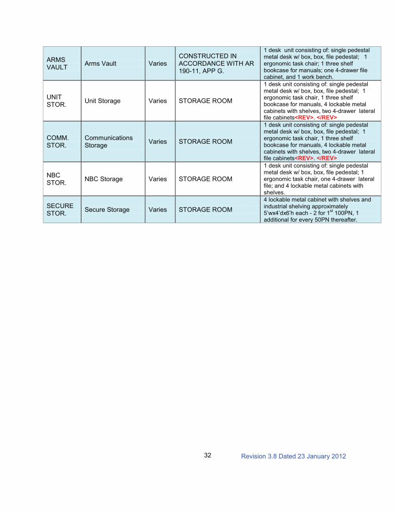
Revision 3.8 Dated 23 January 2012
32
ARMS VAULT
Arms Vault VariesCONSTRUCTED IN ACCORDANCE WITH AR 190-11, APP G.
1 desk unit consisting of: single pedestal metal desk w/ box, box, file pedestal; 1 ergonomic task chair; 1 three shelf bookcase for manuals; one 4-drawer file cabinet, and 1 work bench.
UNIT STOR.
Unit Storage Varies STORAGE ROOM
1 desk unit consisting of: single pedestal metal desk w/ box, box, file pedestal; 1 ergonomic task chair, 1 three shelf bookcase for manuals, 4 lockable metal cabinets with shelves, two 4-drawer lateral file cabinets<REV>. </REV>
COMM. STOR.
Communications Storage
Varies STORAGE ROOM
1 desk unit consisting of: single pedestal metal desk w/ box, box, file pedestal; 1 ergonomic task chair, 1 three shelf bookcase for manuals, 4 lockable metal cabinets with shelves, two 4-drawer lateral file cabinets<REV>. </REV>
NBC STOR.
NBC Storage Varies STORAGE ROOM
1 desk unit consisting of: single pedestal metal desk w/ box, box, file pedestal; 1 ergonomic task chair, one 4-drawer lateral file; and 4 lockable metal cabinets with shelves.
SECURE STOR.
Secure Storage Varies STORAGE ROOM
4 lockable metal cabinet with shelves and industrial shelving approximately 5’wx4’dx6’h each - 2 for 1
st100PN, 1
additional for every 50PN thereafter.

Revision 3.8 Dated 23 January 2012
33
Table 1.1: Room Size and Furnishings Chart for Troop Aid Station (TAS)
Table 1.1 - Room Size and Furnishings Chart for Troop Aid Station (TAS)
Room Description NSF Comments Furniture Required
Waiting Room
Waiting room 480 Public areaSeating to accommodate 15 people,magazine rack, brochure rack and end tables.
ADMIN. / MED RECORDS
Reception,administrative and records storage
152
Reception/check in, private and secure room for safe keeping of medical records. Visual control of waiting room.
2 - Countertops, 2 - ergonomic task chairs, 2 - sitting height base cabinets (pullboard above two drawers and file drawer), 3 - two drawer lateral files.
SCREENING ROOM
Screening rooms89 x 2
Private room adjacent to waiting room.
48” work surface with wall mounted overhead cabinet, 1 - mobile general storage cart (42”H x 32”Wx 22”D), 1 - task chair, 1 - guest chair.
EXAM ROOM
Exam rooms 115 x 4 Private room
1 - Cubicle curtain with surface mounted track, 1 - 48” work surface with wall mounted overhead cabinet, 1 - mobile general storage cart (42”H x 32”Wx 22”D), 1- task chair, 1 - guest chair, 1 - self adjusting stool, 1 - examination / treatment table with cabinet.
PHAR. /STOR./OPT. EXAM ROOM
Medicine and equipment storage –Optional exam for surge situations.
115Private and secure room,preferably on the interior,with no windows.
1 -Cubicle curtain with surface mounted track, 1 - 48” work surface with wallmounted overhead cabinet, 1 - mobile general storage cart (42”H x 32”Wx 22”D), 1- task chair, 1 - guest chair, 1 - self adjusting stool, 1 - examination / treatment table with cabinet.
NOTES:1. All furniture items identified in Table 1.1 above are provided for initial coordination of TAS room layouts to ensure suitability for their intended function. These items are described in detail and located at Appendix entitled TROOP AID STATION FURNISHINGS.2. Examination/treatment table with cabinet is a hospital equipment item that is specified, purchased and installed by others, i.e. Government Furnished Government (GFGI).3. Countertops, base cabinets, and cubicle curtain and track are Contractor Furnished Contractor Installed (CFCI) items.4. Troop Aid Station Furnishings Attachment further clarifies what is: (1) Contractor Furnished Contractor Installed (CFCI); (2) Hospital Equipment (Hosp Equip) – specified, purchased and installed by others, i.e.Government Furnished Government Installed (GFGI): and (3) Furniture, Fixtures and Equipment (FF&E) – designed by AE but purchased and installed by others, i.e. Government Furnished Government Installed (GFGI). 5. Go to http://usahfpa.amedd.army.mil, HFPA Construction and Planning References, Criteria, Space Planning and Guideplates, Military Handbook 1691 for additional information on the joint schedule numbers (JSN), category of logistical responsibility (LOG CAT), and utility requirements (Utl).
Revision 3.8 Dated 23 January 2012
34
3.3.10 References
(1) Army Regulation 190-11 Physical Security of Arms, Ammunition and Explosives
(2) Army Regulation 190–13 The Army Physical Security Program
(3) Army Regulation 190-51, Security of Unclassified Army Property (Sensitive and Nonsensitive)
(4) Army Regulation 380–5 Information Security Program
(5) Army Regulation 380–19 Information Systems Security
(6) Fed Spec AA-V-2737, Modular Vault Systems
(7) Uniform Federal Accessibility Standards (UFAS)
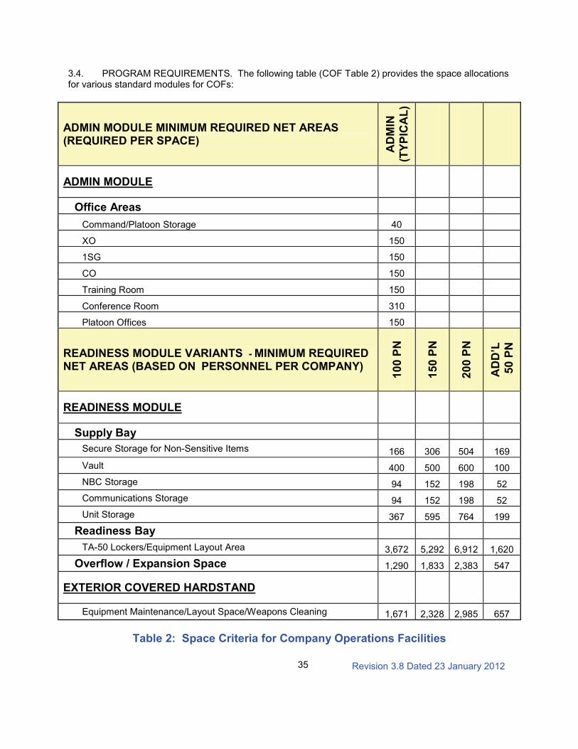
Revision 3.8 Dated 23 January 2012
35
3.4. PROGRAM REQUIREMENTS. The following table (COF Table 2) provides the space allocations for various standard modules for COFs:
Table 2: Space Criteria for Company Operations Facilities
ADMIN MODULE MINIMUM REQUIRED NET AREAS (REQUIRED PER SPACE)
AD
MIN
(TY
PIC
AL
)
ADMIN MODULE
Office Areas
Command/Platoon Storage 40
XO 150
1SG 150
CO 150
Training Room 150
Conference Room 310
Platoon Offices 150
READINESS MODULE VARIANTS - MINIMUM REQUIRED NET AREAS (BASED ON PERSONNEL PER COMPANY)
10
0 P
N
15
0 P
N
20
0 P
N
AD
D’L
50
PN
READINESS MODULE
Supply Bay
Secure Storage for Non-Sensitive Items 166 306 504 169
Vault 400 500 600 100
NBC Storage 94 152 198 52
Communications Storage 94 152 198 52
Unit Storage 367 595 764 199
Readiness Bay
TA-50 Lockers/Equipment Layout Area 3,672 5,292 6,912 1,620
Overflow / Expansion Space 1,290 1,833 2,383 547
EXTERIOR COVERED HARDSTAND
Equipment Maintenance/Layout Space/Weapons Cleaning 1,671 2,328 2,985 657
Revision 3.8 Dated 23 January 2012
36
COMPANY OPERATIONS FACILITY(COF)
TROOP AID STATION FURNISHINGS APPENDIX
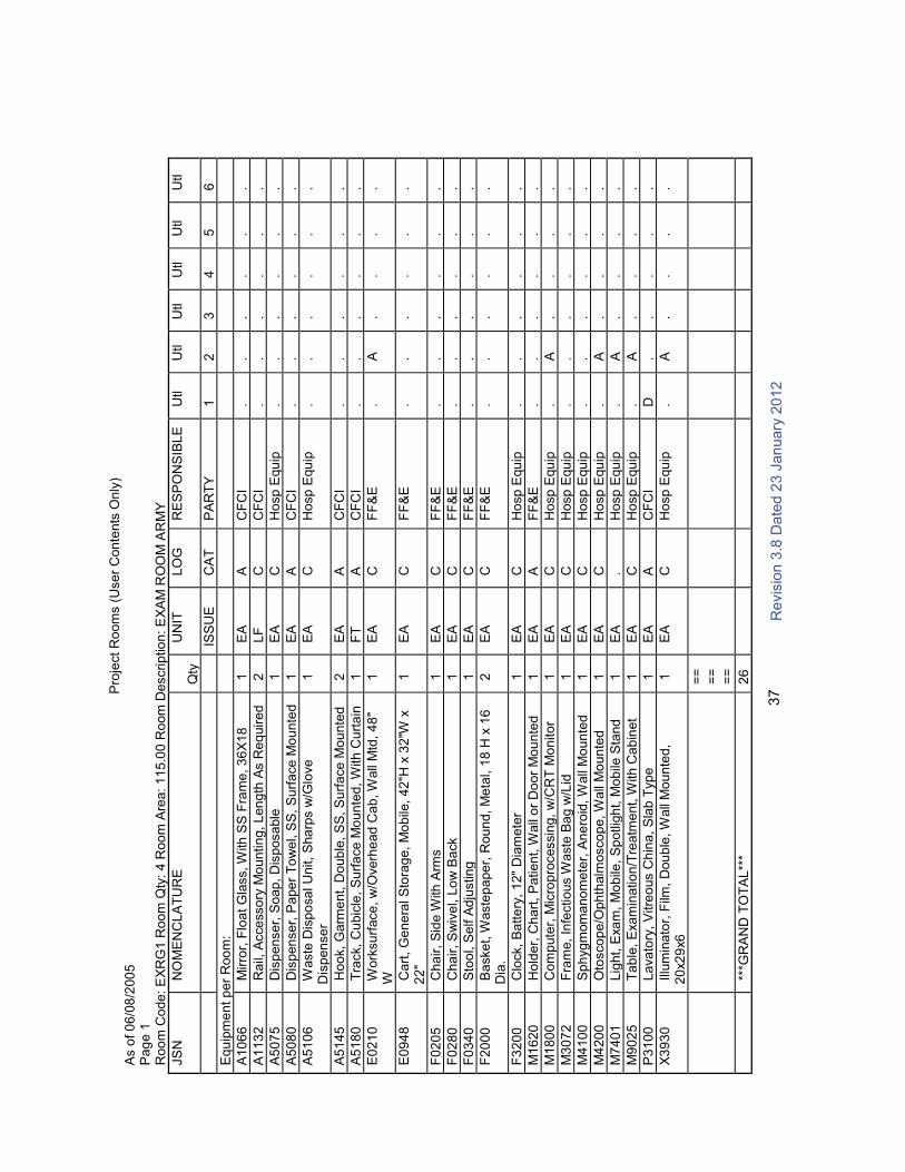
R
evis
ion
3.8
Da
ted 2
3 J
an
uary
20
12
37P
roje
ct
Ro
om
s (
Use
r C
on
ten
ts O
nly
)A
s o
f 0
6/0
8/2
00
5P
ag
e 1
Ro
om
Co
de
: E
XR
G1
Ro
om
Qty
: 4
Ro
om
Are
a: 1
15
.00
Ro
om
De
scrip
tio
n:
EX
AM
RO
OM
AR
MY
JS
NN
OM
EN
CL
AT
UR
EQ
tyU
NIT
LO
GR
ES
PO
NS
IBL
EU
tlU
tlU
tlU
tlU
tlU
tl
ISS
UE
CA
TP
AR
TY
12
34
56
Eq
uip
me
nt p
er
Roo
m:
A1
06
6M
irro
r, F
loa
t G
lass, W
ith
SS
Fra
me
, 3
6X
18
1E
AA
CF
CI
..
..
..
A1
13
2R
ail,
Acce
sso
ry M
ou
ntin
g, L
en
gth
As R
eq
uir
ed
2L
FC
CF
CI
..
..
..
A5
07
5D
isp
en
se
r, S
oap
, D
isp
osa
ble
1E
AC
Ho
sp
Equ
ip.
..
..
.
A5
08
0D
isp
en
se
r, P
ape
r T
ow
el, S
S,
Su
rfa
ce
Mo
un
ted
1E
AA
CF
CI
..
..
..
A5
10
6W
aste
Dis
po
sa
l U
nit,
Sha
rps w
/Glo
ve
D
isp
en
se
r1
EA
CH
osp
Equ
ip.
..
..
.
A5
14
5H
oo
k,
Ga
rme
nt,
Do
ub
le, S
S, S
urf
ace
Mo
un
ted
2E
AA
CF
CI
..
..
..
A5
18
0T
rack,
Cu
bic
le,
Su
rfa
ce
Mo
un
ted
, W
ith
Cu
rta
in1
FT
AC
FC
I.
..
..
.
E0
21
0W
ork
su
rface
, w
/Ove
rhe
ad
Ca
b, W
all
Mtd
, 4
8"
W1
EA
CF
F&
E.
A.
..
.
E0
94
8C
art
, G
en
era
l S
tora
ge,
Mo
bile
, 4
2"H
x 3
2"W
x
22
"1
EA
CF
F&
E.
..
..
.
F0
20
5C
ha
ir,
Sid
e W
ith
Arm
s1
EA
CF
F&
E.
..
..
.
F0
28
0C
ha
ir,
Sw
ive
l, L
ow
Ba
ck
1E
AC
FF
&E
..
..
..
F0
34
0S
too
l, S
elf A
dju
stin
g1
EA
CF
F&
E.
..
..
.
F2
00
0B
aske
t, W
aste
pa
pe
r, R
ou
nd
, M
eta
l, 1
8 H
x 1
6
Dia
.2
EA
CF
F&
E.
..
..
.
F3
20
0C
lock,
Ba
tte
ry,
12"
Dia
me
ter
1E
AC
Ho
sp
Equ
ip.
..
..
.
M1
62
0H
old
er,
Ch
art
, P
atien
t, W
all
or
Do
or
Mo
un
ted
1E
AA
FF
&E
..
..
..
M1
80
0C
om
pute
r, M
icro
pro
cessin
g, w
/CR
T M
on
ito
r1
EA
CH
osp
Equ
ip.
A.
..
.
M3
07
2F
ram
e,
Infe
ctio
us W
aste
Ba
g w
/Lid
1E
AC
Ho
sp
Equ
ip.
..
..
.
M4
10
0S
ph
yg
mom
ano
mete
r, A
ne
roid
, W
all
Mo
un
ted
1E
AC
Ho
sp
Equ
ip.
..
..
.
M4
20
0O
tosco
pe
/Oph
thalm
osco
pe
, W
all
Mo
un
ted
1E
AC
Ho
sp
Equ
ip.
A.
..
.
M7
40
1L
ight,
Exa
m,
Mo
bile
, S
potlig
ht, M
ob
ile S
tand
1E
A.
Ho
sp
Equ
ip.
A.
..
.
M9
02
5T
ab
le,
Exa
min
atio
n/T
rea
tme
nt,
With C
ab
ine
t1
EA
CH
osp
Equ
ip.
A.
..
.
P3
10
0L
ava
tory
, V
itre
ous C
hin
a,
Sla
b T
yp
e1
EA
AC
FC
ID
..
..
.
X3
93
0Illu
min
ato
r, F
ilm,
Dou
ble
, W
all
Mo
un
ted
, 2
0x2
9x6
1E
AC
Ho
sp
Equ
ip.
A.
..
.
==
==
==
***G
RA
ND
TO
TA
L**
*2
6

R
evis
ion
3.8
Da
ted 2
3 J
an
uary
20
12
38
Refe
rence P
ara
gra
ph 3
.3.8
Furn
iture
Syste
ms, T
able
1.1
, N
ote
5 f
or
add
itio
nal in
form
ation.
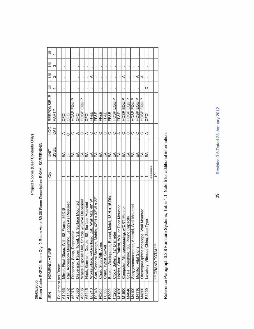
R
evis
ion
3.8
Da
ted 2
3 J
an
uary
20
12
39P
roje
ct
Ro
om
s (
Use
r C
on
ten
ts O
nly
)0
6/0
9/2
005
Ro
om
Co
de
: E
XR
G4
Ro
om
Qty
: 2
Ro
om
Are
a: 8
9.0
0 R
oom
De
scrip
tio
n:
EX
AM
, S
CR
EE
NIN
G
JS
NN
OM
EN
CL
AT
UR
EQ
tyU
NIT
LO
GR
ES
PO
NS
IBL
E
Utl
Utl
Utl
Utl
ISS
UE
CA
TP
AR
TY
12
34
Eq
uip
me
nt p
er
Roo
m:
A1
06
6M
irro
r, F
loa
t G
lass, W
ith
SS
Fra
me
, 3
6X
18
1E
AA
CF
CI
..
..
A1
13
2R
ail,
Accesso
ry M
ou
ntin
g,
Le
ng
th A
s R
eq
uir
ed
1
LF
CC
FC
I
A5
07
5D
isp
en
se
r, S
oa
p,
Dis
posa
ble
1E
AC
HO
SP
EQ
UIP
..
..
A5
08
0D
isp
en
se
r, P
ap
er
To
we
l, S
S,
Su
rfa
ce
Mo
un
ted
1E
AA
CF
CI
..
..
A5
10
6W
aste
Dis
po
sa
l U
nit,
Sha
rps w
/Glo
ve
Dis
pe
nse
r1
EA
CH
OS
P E
QU
IP.
..
.
A5
14
5H
oo
k,
Ga
rme
nt, D
ou
ble
, S
S, S
urf
ace
Mo
un
ted
1E
AA
CF
CI
..
..
E0
21
0W
ork
su
rface
, w
/Ove
rhe
ad
Cab
, W
all
Mtd
, 4
8"
W1
EA
CF
F&
E.
A.
.
E0
94
8C
art
, G
en
era
l S
tora
ge
, M
ob
ile, 4
2"H
x 3
2"W
x 2
2"
1E
AC
FF
&E
..
..
F0
20
5C
ha
ir,
Sid
e W
ith
Arm
s1
EA
CF
F&
E.
..
.
F0
30
0C
ha
ir,
Typ
ist,
Sw
ive
l1
EA
CF
F&
E.
..
.
F2
00
0B
aske
t, W
aste
pa
pe
r, R
oun
d, M
eta
l, 1
8 H
x 1
6 D
ia.
1E
AC
FF
&E
..
..
F3
20
0C
lock,
Ba
tte
ry,
12
" D
iam
ete
r1
EA
CH
OS
P E
QU
IP.
..
.
M1
62
0H
old
er,
Cha
rt,
Pa
tien
t, W
all
or
Do
or
Mo
un
ted
1E
AA
FF
&E
..
..
M1
80
0C
om
pu
ter,
Mic
rop
rocessin
g,
w/C
RT
Mo
nito
r1
EA
CH
OS
P E
QU
IP.
A.
.
M4
04
0S
ca
le, W
eig
hin
g, 3
00
Po
un
d C
ap
acity
1E
AC
HO
SP
EQ
UIP
..
..
M4
10
0S
ph
yg
mom
ano
me
ter,
Ane
roid
, W
all
Mo
un
ted
1E
AC
HO
SP
EQ
UIP
..
..
M4
11
6M
on
ito
r, V
ita
l S
igns
1E
AC
HO
SP
EQ
UIP
.A
..
M4
20
0O
toscop
e/O
phth
alm
oscop
e, W
all
Mo
un
ted
1E
AC
HO
SP
EQ
UIP
.A
..
P3
10
0L
ava
tory
, V
itre
ou
s C
hin
a,
Sla
b T
yp
e1
EA
AC
FC
ID
..
.
==
==
==
***G
RA
ND
TO
TA
L**
*1
9
Refe
rence P
ara
gra
ph 3
.3.8
Furn
iture
Syste
ms, T
able
1.1
, N
ote
5 f
or
add
itio
nal in
form
ation.
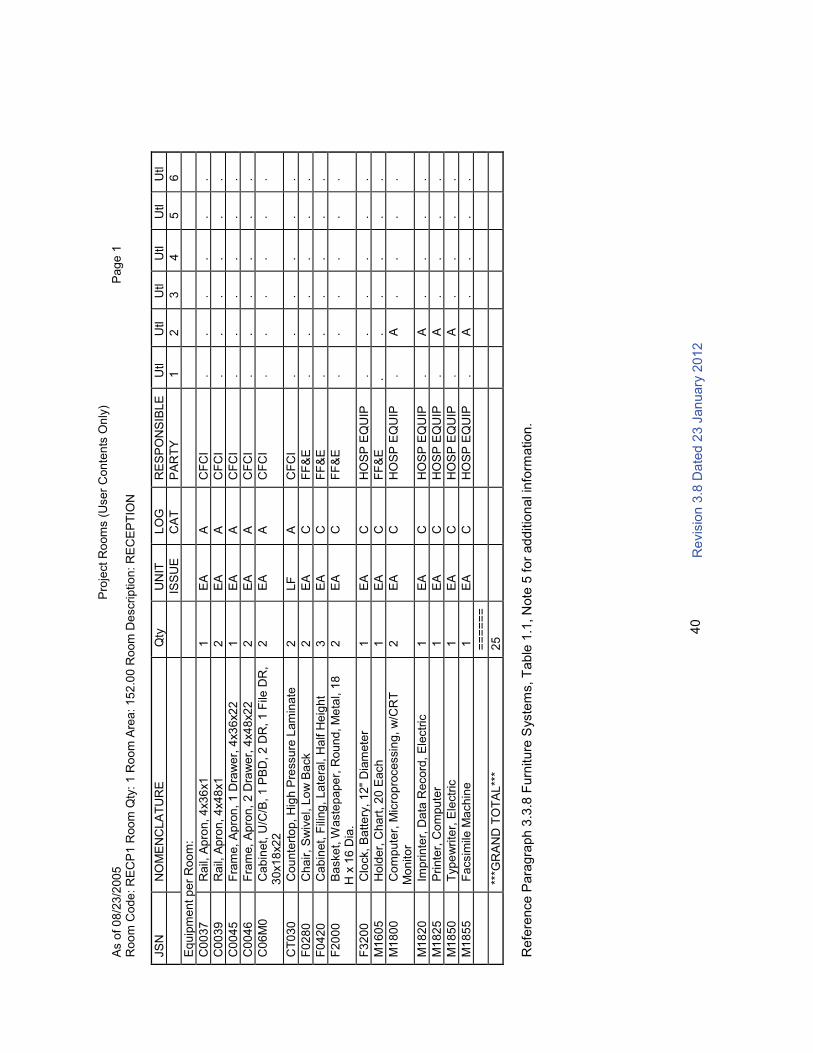
R
evis
ion
3.8
Da
ted 2
3 J
an
uary
20
12
40
Pro
ject
Ro
om
s (
Use
r C
on
ten
ts O
nly
)A
s o
f 0
8/2
3/2
00
5P
ag
e 1
Ro
om
Co
de
: R
EC
P1
Roo
m Q
ty:
1 R
oo
m A
rea
: 1
52
.00
Ro
om
De
scrip
tio
n:
RE
CE
PT
ION
JS
NN
OM
EN
CL
AT
UR
EQ
tyU
NIT
LO
GR
ES
PO
NS
IBL
EU
tlU
tlU
tlU
tlU
tlU
tl
ISS
UE
CA
TP
AR
TY
12
34
56
Eq
uip
me
nt p
er
Roo
m:
C0
03
7R
ail,
Ap
ron
, 4
x3
6x1
1E
AA
CF
CI
..
..
..
C0
03
9R
ail,
Ap
ron
, 4
x4
8x1
2E
AA
CF
CI
..
..
..
C0
04
5F
ram
e,
Ap
ron
, 1
Dra
we
r, 4
x3
6x2
21
EA
AC
FC
I.
..
..
.
C0
04
6F
ram
e,
Ap
ron
, 2
Dra
we
r, 4
x4
8x2
22
EA
AC
FC
I.
..
..
.
C0
6M
0C
ab
inet,
U/C
/B, 1
PB
D,
2 D
R, 1
File
DR
, 3
0x1
8x2
22
EA
AC
FC
I.
..
..
.
CT
03
0C
ou
nte
rto
p,
Hig
h P
ressu
re L
am
inate
2L
FA
CF
CI
..
..
..
F0
28
0C
ha
ir,
Sw
ive
l, L
ow
Ba
ck
2E
AC
FF
&E
..
..
..
F0
42
0C
ab
inet,
Fili
ng
, La
tera
l, H
alf H
eig
ht
3E
AC
FF
&E
..
..
..
F2
00
0B
aske
t, W
aste
pa
pe
r, R
ou
nd
, M
eta
l, 1
8
H x
16
Dia
.2
EA
CF
F&
E.
..
..
.
F3
20
0C
lock,
Ba
tte
ry,
12"
Dia
me
ter
1E
AC
HO
SP
EQ
UIP
..
..
..
M1
60
5H
old
er,
Ch
art
, 2
0 E
ach
1E
AC
FF
&E
..
..
..
M1
80
0C
om
pute
r, M
icro
pro
cessin
g, w
/CR
T
Mo
nito
r2
EA
CH
OS
P E
QU
IP.
A.
..
.
M1
82
0Im
prin
ter,
Da
ta R
eco
rd,
Ele
ctr
ic1
EA
CH
OS
P E
QU
IP.
A.
..
.
M1
82
5P
rin
ter,
Co
mpu
ter
1E
AC
HO
SP
EQ
UIP
.A
..
..
M1
85
0T
yp
ew
rite
r, E
lectr
ic1
EA
CH
OS
P E
QU
IP.
A.
..
.
M1
85
5F
acsim
ile M
ach
ine
1E
AC
HO
SP
EQ
UIP
.A
..
..
==
==
==
***G
RA
ND
TO
TA
L**
*2
5
Refe
rence P
ara
gra
ph 3
.3.8
Furn
iture
Syste
ms, T
able
1.1
, N
ote
5 f
or
add
itio
nal in
form
ation.

UP
UP
UP
UP
UP
UP
UP
UP
169'
-2"
169'
-2"
98'-4
"
74'-6"20'-0"30'-0"
436'
-8"
SE
CU
RE
NO
N-S
EN
S.
ST
OR
AG
EU
NIT
ST
OR
AG
EA
RM
SV
AU
LT
CO
MM
.S
TO
RA
GE
NB
CS
TO
RA
GE
TA
-50
GE
AR
ST
OR
AG
E
SE
CU
RE
NO
N-S
EN
S.
ST
OR
AG
EU
NIT
ST
OR
AG
EA
RM
SV
AU
LT
CO
MM
.S
TO
RA
GE
NB
CS
TO
RA
GE
TA
-50
GE
AR
ST
OR
AG
E
XO
CO
. C
DR
.
TR
AIN
ING
RO
OM
1S
G
PLA
TO
ON
OF
FIC
E
PLA
TO
ON
OF
FIC
E
PLA
TO
ON
OF
FIC
E
PLA
TO
ON
OF
FIC
E
PLA
TO
ON
OF
FIC
E
PLA
TO
ON
OF
FIC
E
PLA
TO
ON
OF
FIC
E
PLA
TO
ON
OF
FIC
E
TR
AIN
ING
RO
OM
1S
G
XO
CO
. C
DR
.
CONFERENCE
ST
OR
.S
TO
R.
CO
NF
ER
EN
CE
ST
OR
.R
EC
.S
TO
R.
JA
N.
ME
NW
OM
EN
VE
ST
.
CO
RR
IDO
R
CO
MM
.
ELE
C.
ME
CH
AN
ICA
L
CO
NF
ER
EN
CE
CONFERENCE
ST
OR
.S
TO
R.
ST
OR
.
XO
CO
. C
DR
.
TR
AIN
ING
RO
OM
1S
G
PLA
TO
ON
OF
FIC
E
PLA
TO
ON
OF
FIC
E
PLA
TO
ON
OF
FIC
E
PLA
TO
ON
OF
FIC
E
TR
AIN
ING
RO
OM
1S
G
XO
CO
. C
DR
.
SE
CU
RE
NO
N-S
EN
S.
ST
OR
AG
EU
NIT
ST
OR
AG
EA
RM
SV
AU
LT
CO
MM
.S
TO
RA
GE
NB
CS
TO
RA
GE
TA
-50 G
EA
R S
TO
RA
GE
SE
CU
RE
NO
N-S
EN
S.
ST
OR
AG
EU
NIT
ST
OR
AG
EA
RM
SV
AU
LT
CO
MM
.S
TO
RA
GE
NB
CS
TO
RA
GE
TA
-50
GE
AR
ST
OR
AG
E
15
0P
N C
OM
PA
NY
15
0P
N C
OM
PA
NY
15
0P
N C
OM
PA
NY
15
0P
N C
OM
PA
NY
ADMIN. MODULEREADINESS MODULEEXTERIOR COVERED HARDSTAND
98'-0
"98
'-0"
98'-0
"98
'-0"
BO
ILE
R R
OO
M
VE
ND
ING
/R
EC
YC
LE
.
34'-10" 10'-3 3/4"
397'
-3 3
/4"
SH
EE
TID
EN
TIF
ICA
TIO
N
12
34
5
DRAWNBY:
DESIGNBY:
SBMTBY:
SIZE:FILENAME:
DATE:
CONTRACTNO.:
SOLICITATIONNO.:
US ARMY CORPS OF ENGINEERS
CKDBY:
US
Arm
y C
orp
s o
fE
ng
ineers
®
22"x34"
D C B A
FILENUMBER: PLOTSCALE:
PLOTDATE:
SH
EE
TO
F
1/27/201212:26:06 PM
Savannah D
istr
ict
Designer
Author
Approver
A-1
01C
SavannahDistrictChecker
03-7COMPANYOPTIONWITHINTEGRATEDADMIN
PROJECTNAME:
A-101C-
MARKDESCRIPTIONDATEAPPR
NO
TE
:P
LA
TO
ON
OF
FIC
ES
AR
E D
ISP
LA
CE
D T
O R
EA
DIN
ES
S M
OD
ULE
ME
ZZ
AN
INE
WH
EN
AD
MIN
MO
DU
LE
IS
CO
NF
IGU
RE
D F
RO
M 5
TO
7 C
OM
PA
NIE
S T
O A
CC
OM
MO
DA
TE
AD
DIT
ION
AL C
OM
MA
ND
SU
ITE
S.
FIR
ST
FLO
OR
PLA
N
NO
TE
: IN
EX
TR
EM
E C
OLD
RE
GIO
NS
, E
XT
ER
IOR
CO
VE
RE
DH
AR
DS
TA
ND
AR
EA
S M
AY
BE
PH
YS
ICA
LLY
AT
TA
CH
ED
TO
TH
ER
EA
DIN
ES
S M
OD
ULE
AN
D E
NC
LO
SE
D A
LL S
IDE
S. R
EF
ER
TO
RF
P S
EC
TIO
N 0
1 1
0 0
0, P
AR
AG
RA
PH
6, F
OR
SP
EC
IFIC
PR
OJE
CT
RE
QU
IRE
ME
NT
S.
A
RE
A A
S S
HO
WN
A
LLO
WA
BLE
AD
MIN
IST
RA
TIO
N M
OD
ULE
: 16,0
56 sq. ft.*
16,6
00 sq. ft
.R
EA
DIN
ES
S M
OD
ULE
: F
irst F
loor:
29,6
25 s
q. ft
.* M
ezzanin
e: 6
,709 s
q. ft
.*T
OT
AL: 3
6,3
34 sq. ft
. *
38,4
00 sq. ft
.
EX
TE
RIO
R H
AR
DS
TA
ND
: 9
,320 s
q. ft.
* p
redic
ate
d o
n a
n a
ssum
ed e
xte
rior
wall
thic
kness o
f 18 inches f
or
the
Adm
inis
tration a
nd R
eadin
ess M
odule
s.
AR
EA
NO
TE
ST
he f
loor
pla
ns indic
ate
the A
rmy S
tandard
Desig
n in s
chem
atic form
. T
he d
esig
ner-
of-
record
(D-O
-R)
is a
llow
ed to m
ake a
dju
stm
ents
for
the e
xte
rior
façade/a
rchitectu
re them
e, and/o
r to
accom
modate
specific
build
ing e
ngin
eering s
yste
ms (
str
uctu
ral, m
echanic
al, e
lectr
ical, fire
pro
tection, susta
inable
desig
n, etc
.). T
hese a
dju
stm
ents
will
be e
valu
ate
d b
y the C
ente
r of
Sta
ndard
ization (
CoS
) during its
com
plia
nce r
evie
w.
The o
vera
ll build
ing d
imensio
ns a
nd the v
alu
es for
the g
ross b
uild
ing a
reas indic
ate
d a
re for
the
sta
ndard
layo
uts
show
n a
nd a
re p
redic
ate
d o
n a
n a
ssum
ed e
xte
rior
wall
thic
kness o
f 18 inches.
It is u
nders
tood that th
e a
ctu
al gro
ss b
uild
ing a
rea w
ill v
ary
dependin
g o
n the w
all
sys
tem
/m
ate
rial sele
cte
d f
or
a s
pecific
pro
ject. A
reduced o
vera
ll gro
ss a
rea is p
erm
issib
le if all
net
pro
gra
m r
equirem
ents
and a
dja
cencie
s a
re s
atisfied, but in
no c
ase m
ay the m
axim
um
gro
ss
are
a f
or
the facili
ty b
e e
xceeded.
CO
VE
RE
D H
AR
DS
TA
ND
TY
PIC
AL B
UIL
DIN
G R
EA
DIN
ES
S M
OD
ULE
EX
PA
NS
ION
AD
MIN
. M
OD
ULE
RE
AD
INE
SS
MO
DU
LE
EX
TE
RIO
R C
OV
ER
ED
HA
RD
ST
AN
D
<R
EV
>
</R
EV
>
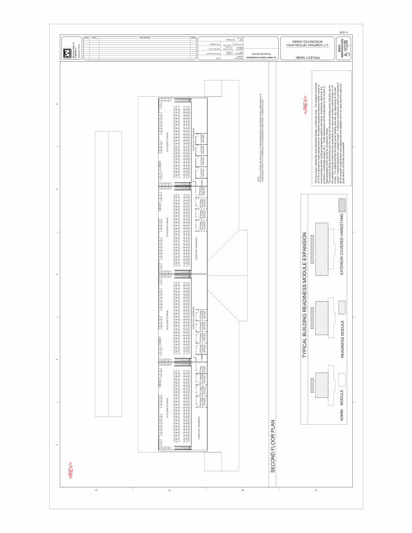
DN
DN
DN
DN
DN
DN
DN
DN
OV
ER
FLO
W / E
XP
AN
SIO
NO
PT
ION
AL
PLA
TO
ON
OF
FIC
ES
OP
TIO
NA
LP
LA
TO
ON
OF
FIC
ES
OP
TIO
NA
LP
LA
TO
ON
OF
FIC
ES
OP
TIO
NA
LP
LA
TO
ON
OF
FIC
ES
OP
TIO
NA
LP
LA
TO
ON
OF
FIC
ES
OP
TIO
NA
LP
LA
TO
ON
OF
FIC
ES
OP
TIO
NA
LP
LA
TO
ON
OF
FIC
ES
OP
TIO
NA
LP
LA
TO
ON
OF
FIC
ES
CO
MM
.O
PT
ION
AL
PLA
TO
ON
OF
FIC
ES
OP
TIO
NA
LP
LA
TO
ON
OF
FIC
ES
OP
TIO
NA
LP
LA
TO
ON
OF
FIC
ES
OP
TIO
NA
LP
LA
TO
ON
OF
FIC
ES
PLA
TO
ON
OF
FIC
ES
PLA
TO
ON
OF
FIC
ES
PLA
TO
ON
OF
FIC
ES
PLA
TO
ON
OF
FIC
ES
CO
MM
.
OV
ER
FLO
W / E
XP
AN
SIO
N
OV
ER
FLO
W / E
XP
AN
SIO
N
OV
ER
FLO
W / E
XP
AN
SIO
N
TA
-50 G
EA
R S
TO
RA
GE
TA
-50 G
EA
R S
TO
RA
GE
TA
-50 G
EA
R S
TO
RA
GE
TA
-50 G
EA
R S
TO
RA
GE
SH
EE
TID
EN
TIF
ICA
TIO
N
12
34
5
DRAWNBY:
DESIGNBY:
SBMTBY:
SIZE:FILENAME:
DATE:
CONTRACTNO.:
SOLICITATIONNO.:
US ARMY CORPS OF ENGINEERS
CKDBY:
US
Arm
y C
orp
s o
fE
ng
ineers
®
22"x34"
D C B A
FILENUMBER: PLOTSCALE:
PLOTDATE:
SH
EE
TO
F
1/27/201211:40:47 AM
Savannah D
istr
ict
Designer
SCM
Approver
A-1
02B
SavannahDistrictChecker
03-7COMPANYOPTIONWITHINTEGRATEDADMIN
PROJECTNAME:
A-102B-
MARKDESCRIPTIONDATEAPPR
NO
TE
:P
LA
TO
ON
OF
FIC
ES
AR
E D
ISP
LA
CE
D T
O R
EA
DIN
ES
S M
OD
ULE
ME
ZZ
AN
INE
WH
EN
AD
MIN
MO
DU
LE
IS
CO
NF
IGU
RE
D F
RO
M 5
TO
7 C
OM
PA
NIE
S T
O A
CC
OM
MO
DA
TE
AD
DIT
ION
AL C
OM
MA
ND
SU
ITE
S.
SE
CO
ND
FLO
OR
PLA
N
The f
loor
pla
ns indic
ate
the A
rmy S
tandard
Desig
n in s
chem
atic form
. T
he d
esig
ner-
of-
record
(D-O
-R)
is a
llow
ed to m
ake a
dju
stm
ents
for
the e
xte
rior
façade/a
rchitectu
re them
e, and/o
r to
accom
modate
specific
build
ing e
ngin
eering s
yste
ms (
str
uctu
ral, m
echanic
al, e
lectr
ical, fire
pro
tection, susta
inable
desig
n, etc
.). T
hese a
dju
stm
ents
will
be e
valu
ate
d b
y the C
ente
r of
Sta
ndard
ization (
CoS
) during its
com
plia
nce r
evie
w.
The o
vera
ll build
ing d
imensio
ns a
nd the v
alu
es for
the g
ross b
uild
ing a
reas indic
ate
d a
re for
the s
tandard
layo
uts
show
n a
nd a
re p
redic
ate
d o
n a
n a
ssum
ed e
xte
rior
wall
thic
kness o
f 18
inches. It is
unders
tood that th
e a
ctu
al gro
ss b
uild
ing a
rea w
ill v
ary
dependin
g o
n the w
all
syste
m / m
ate
rial sele
cte
d f
or
a s
pecific
pro
ject. A
reduced o
vera
ll gro
ss a
rea is p
erm
issib
le if
all
net pro
gra
m r
equirem
ents
and a
dja
cencie
s a
re s
atisfied, but in
no c
ase m
ay
the m
axim
um
gro
ss a
rea f
or
the facili
ty b
e e
xceeded.
TY
PIC
AL B
UIL
DIN
G R
EA
DIN
ES
S M
OD
ULE
EX
PA
NS
ION
AD
MIN
M
OD
ULE
RE
AD
INE
SS
MO
DU
LE
EX
TE
RIO
R C
OV
ER
ED
HA
RD
ST
AN
D
<R
EV
>
</R
EV
>
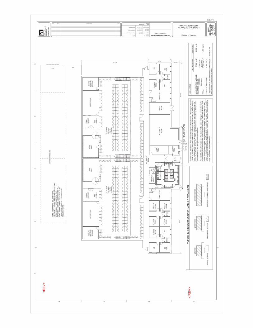
UP
UP
UP
UP
SE
CU
RE
NO
N-S
EN
S.
ST
OR
AG
E
UN
IT S
TO
RA
GE
AR
MS
VA
ULT
CO
MM
.S
TO
RA
GE
NB
CS
TO
RA
GE TA
-50
GE
AR
ST
OR
AG
E15
0 P
NC
OM
PA
NY
SE
CU
RE
NO
N-S
EN
S.
ST
OR
AG
E
UN
IT S
TO
RA
GE
AR
MS
VA
ULT
CO
MM
.S
TO
RA
GE
NB
CS
TO
RA
GE
TA
-50
GE
AR
ST
OR
AG
E15
0 P
NC
OM
PA
NY
XO
CO
.C
DR
.
XO
TR
AIN
ING
RO
OM
1 S
G.
TR
AIN
ING
RO
OM
PLA
TO
ON
OF
FIC
E
PLA
TO
ON
OF
FIC
EP
LAT
OO
NO
FF
ICE
PLA
TO
ON
OF
FIC
E
CO
.C
DR
.
1 S
G.
XO
ST
OR
.
ST
OR
.
ST
OR
.
ST
OR
.
ST
OR
.
CO
NF
ER
EN
CE
BO
ILE
RR
OO
MC
ON
FE
RE
NC
EM
EC
HA
NIC
AL
RO
OM
ELE
CT
RIC
AL
RO
OM
CO
MM
.R
OO
M
JAN
/R
EC
YC
.S
TO
R
VE
ND
ING
/R
EC
YC
LE
ME
N
WO
ME
N
ME
CH
AN
ICA
LR
OO
M
30'-0"
EXTERIOR COVERED HARDSTAND
20'-0"
81'-1 1/4"28'-4"
10'-2 7/8"
78'-5
1/4
"75
'-4"
78'-4
7/8
"
CO
VE
RE
D H
AR
DS
TA
ND
SH
EE
TID
EN
TIF
ICA
TIO
N
12
34
5
DRAWNBY:
DESIGNBY:
SBMTBY:
SIZE:FILENAME:
DATE:
CONTRACTNO.:
SOLICITATIONNO.:
US ARMY CORPS OF ENGINEERS
CKDBY:
US
Arm
y C
orp
s o
fE
ng
ineers
®
22"x34"
D C B A
FILENUMBER: PLOTSCALE:
PLOTDATE:
SH
EE
TO
F
1/27/201211:27:38 AM
Savannah D
istr
ict
Designer
Author
Approver
A-1
01B
SavannahDistrictChecker
08
2COMPANYOPTIONW/INTEGRATEDADMIN
PROJECTNAME:
AA-101B-
MARKDESCRIPTIONDATEAPPR
The f
loor
pla
ns indic
ate
the A
rmy S
tandard
Desig
n in s
chem
atic form
. T
he d
esig
ner-
of-
record
(D-O
-R)
is a
llow
ed to m
ake a
dju
stm
ents
for
the e
xte
rior
façade/a
rchitectu
re them
e, and/o
r to
accom
modate
specific
build
ing e
ngin
eering s
yste
ms (
str
uctu
ral, m
echanic
al, e
lectr
ical, fire
pro
tection, susta
inable
desig
n, etc
.). T
hese a
dju
stm
ents
will
be e
valu
ate
d b
y the C
ente
r of
Sta
ndard
ization (
CoS
) during its
com
plia
nce r
evie
w.
The o
vera
ll build
ing d
imensio
ns a
nd the v
alu
es for
the g
ross b
uild
ing a
reas indic
ate
d a
re for
the s
tandard
layo
uts
show
n a
nd a
re p
redic
ate
d o
n a
n a
ssum
ed e
xte
rior
wall
thic
kness o
f 18
inches. It is u
nders
tood that th
e a
ctu
al gro
ss b
uild
ing a
rea w
ill v
ary
dependin
g o
n the w
all
syste
m / m
ate
rial sele
cte
d f
or
a s
pecific
pro
ject. A
reduced o
vera
ll gro
ss a
rea is p
erm
issib
le if
all
net pro
gra
m r
equirem
ents
and a
dja
cencie
s a
re s
atisfied, but in
no c
ase m
ay
the m
axim
um
gro
ss a
rea f
or
the facili
ty b
e e
xceeded.
3/3
2"
=1'-0"
A-1
01B
1F
IRS
T F
LO
OR
PLA
N
NO
TE
: IN
EX
TR
EM
E C
OL
D R
EG
ION
S,
EX
TE
RIO
R C
OV
ER
ED
HA
RD
ST
AN
D A
RE
AS
MA
YB
E P
HY
SIC
ALLY
AT
TA
CH
ED
TO
TH
ER
EA
DIN
ES
S M
OD
ULE
AN
D E
NC
LO
SE
D A
LL
SID
ES
. R
EF
ER
TO
RF
P S
EC
TIO
N 0
1 1
0 0
0,
PA
RA
GR
AP
H 6
, F
OR
SP
EC
IFIC
PR
OJE
CT
RE
QU
IRE
ME
NT
S.
A
RE
A A
S S
HO
WN
A
LLO
WA
BLE
AD
MIN
IST
RA
TIO
N M
OD
ULE
: 8
,760 sq. ft
.* 8
,800 sq. ft
.R
EA
DIN
ES
S M
OD
ULE
: F
irst F
loor:
14,9
16 s
q. ft
.* M
ezzanin
e: 3
,015 s
q. ft
.*T
OT
AL: 17,9
31 s
q. ft
. *
1
9,2
00 sq. ft
.
EX
TE
RIO
R H
AR
DS
TA
ND
: 4
,660 s
q. ft.
* p
redic
ate
d o
n a
n a
ssum
ed e
xte
rior
wall
thic
kness o
f 18 inches f
or
the
Adm
inis
tration a
nd R
eadin
ess M
odule
s.
AR
EA
NO
TE
S
AD
MIN
. M
OD
ULE
RE
AD
INE
SS
M
OD
ULE
EX
TE
RIO
R C
OV
ER
ED
HA
RD
ST
AN
D
TY
PIC
AL B
UIL
DIN
G R
EA
DIN
ES
S M
OD
ULE
EX
PA
NS
ION
<R
EV
>
</R
EV
>
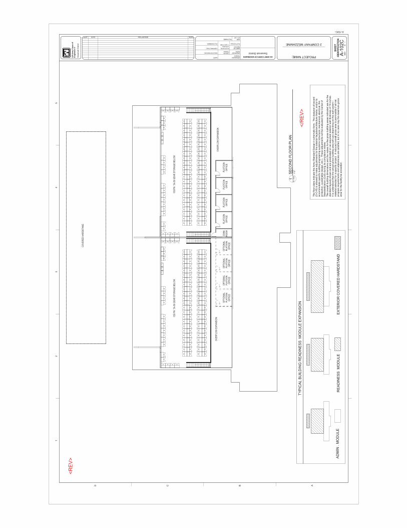
DN
DN
DN
DN
PLA
TO
ON
OF
FIC
EP
LAT
OO
NO
FF
ICE
PLA
TO
ON
OF
FIC
EP
LAT
OO
NO
FF
ICE
CO
MM
.R
OO
MO
PT
ION
AL
PLA
TO
ON
OF
FIC
E
OP
TIO
NA
LP
LAT
OO
NO
FF
ICE
OP
TIO
NA
LP
LAT
OO
NO
FF
ICE
OP
TIO
NA
LP
LAT
OO
NO
FF
ICE
OV
ER
FLO
W E
XP
AN
SIO
NO
VE
RF
LOW
EX
PA
NS
ION
150
PN
TA
-50
GE
AR
ST
OR
AG
E B
ELO
W15
0 P
N T
A-5
0 G
EA
R S
TO
RA
GE
BE
LOW
CO
VE
RE
D H
AR
DS
TA
ND
SH
EE
TID
EN
TIF
ICA
TIO
N
12
34
5
DRAWNBY:
DESIGNBY:
SBMTBY:
SIZE:FILENAME:
DATE:
CONTRACTNO.:
SOLICITATIONNO.:
US ARMY CORPS OF ENGINEERS
CKDBY:
US
Arm
y C
orp
s o
fE
ng
ineers
®
22"x34"
D C B A
FILENUMBER: PLOTSCALE:
PLOTDATE:
SH
EE
TO
F
1/27/201211:29:37 AM
Savannah D
istr
ict
Designer
Author
Approver
A-1
02C
SavannahDistrictChecker
02COMPANYMEZZANINE
PROJECTNAME:
A-102C-
MARKDESCRIPTIONDATEAPPR
3/3
2"
=1'-0"
A-1
02C
1S
EC
ON
D F
LO
OR
PLA
N
The f
loor
pla
ns indic
ate
the A
rmy S
tandard
Desig
n in s
chem
atic form
. T
he d
esig
ner-
of-
record
(D-O
-R)
is a
llow
ed to m
ake a
dju
stm
ents
for
the e
xte
rior
façade/a
rchitectu
re them
e, and/o
r to
accom
modate
specific
build
ing e
ngin
eering s
yste
ms (
str
uctu
ral, m
echanic
al, e
lectr
ical, fire
pro
tection, susta
inable
desig
n, etc
.). T
hese a
dju
stm
ents
will
be e
valu
ate
d b
y the C
ente
r of
Sta
ndard
ization (
CoS
) during its
com
plia
nce r
evie
w.
The o
vera
ll build
ing d
imensio
ns a
nd the v
alu
es for
the g
ross b
uild
ing a
reas indic
ate
d a
re for
the
sta
ndard
layo
uts
show
n a
nd a
re p
redic
ate
d o
n a
n a
ssum
ed e
xte
rior
wall
thic
kness o
f 18 inches.
It is u
nders
tood that th
e a
ctu
al gro
ss b
uild
ing a
rea w
ill v
ary
dependin
g o
n the w
all
sys
tem
/m
ate
rial sele
cte
d f
or
a s
pecific
pro
ject. A
reduced o
vera
ll gro
ss a
rea is p
erm
issib
le if all
net
pro
gra
m r
equirem
ents
and a
dja
cencie
s a
re s
atisfied, but in
no c
ase m
ay the m
axim
um
gro
ss
are
a f
or
the facili
ty b
e e
xceeded.
AD
MIN
. M
OD
ULE
RE
AD
INE
SS
M
OD
ULE
EX
TE
RIO
R C
OV
ER
ED
HA
RD
ST
AN
D
TY
PIC
AL B
UIL
DIN
G R
EA
DIN
ES
S M
OD
ULE
EX
PA
NS
ION
<R
EV
>
</R
EV
>
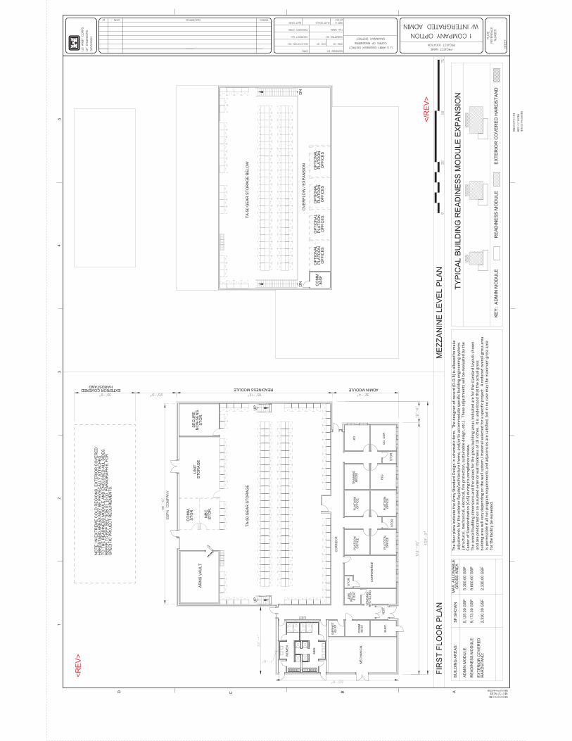
<R
EV
>
</R
EV
>
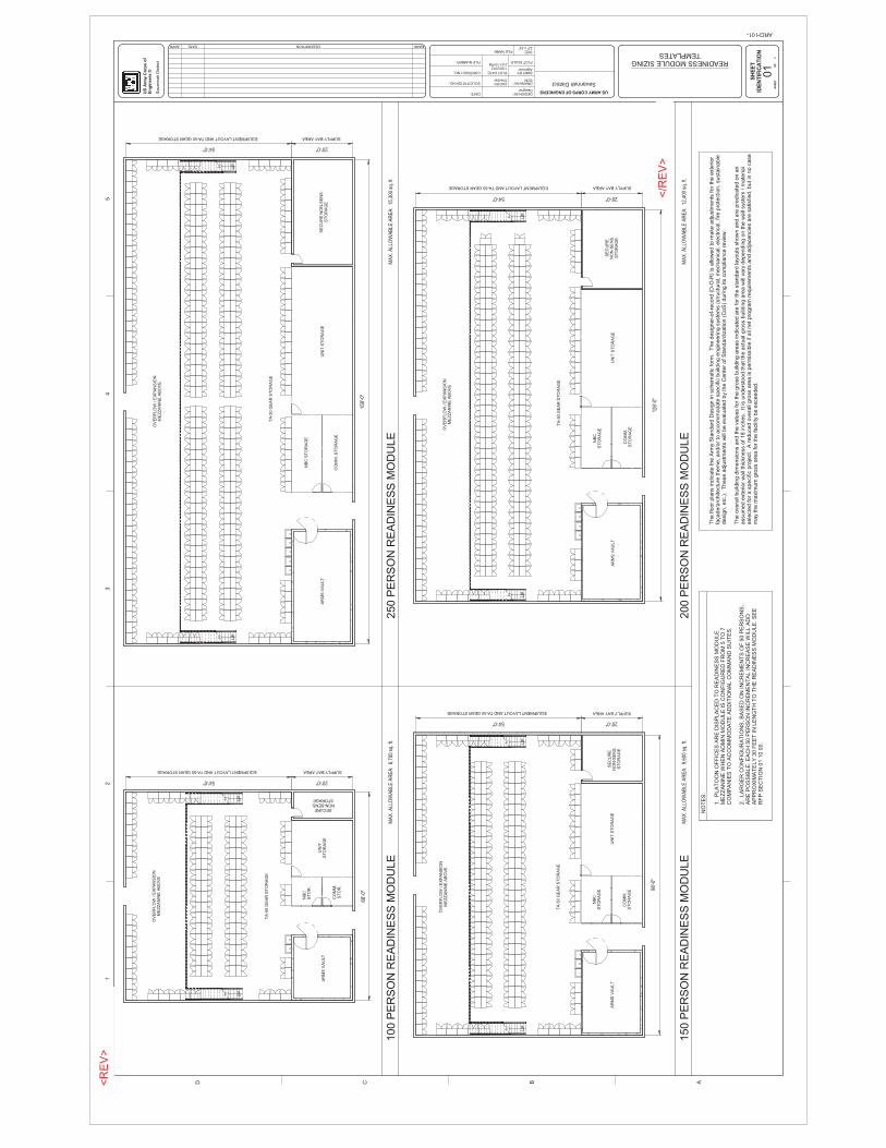
UP
UP
UP
UP
UP
UP
UP
UP
OV
ER
FLO
W / E
XP
AN
SIO
NM
EZ
ZA
NIN
E A
BO
VE
TA
-50 G
EA
R S
TO
RA
GE
SECURENON-SENS.STORAGE
UN
ITS
TO
RA
GE
CO
MM
.S
TO
R.
NB
CS
TO
R.
AR
MS
VA
ULT
SUPPLY BAY AREAEQUIPMENT LAYOUT AND TA-50 GEAR STORAGE
68'-0
"20'-0"54'-0"
OV
ER
FLO
W / E
XP
AN
SIO
NM
EZ
ZA
NIN
E A
BO
VE
SE
CU
RE
NO
N-S
EN
S.
ST
OR
AG
E
UN
IT S
TO
RA
GE
AR
MS
VA
ULT
CO
MM
.S
TO
RA
GE
NB
CS
TO
RA
GE
TA
-50 G
EA
R S
TO
RA
GE
EQUIPMENT LAYOUT AND TA-50 GEAR STORAGE SUPPLY BAY AREA
98'-0
"
20'-0"54'-0"
OV
ER
FLO
W / E
XP
AN
SIO
NM
EZ
ZA
NIN
E A
BO
VE
SE
CU
RE
NO
N-S
EN
S.
ST
OR
AG
EU
NIT
ST
OR
AG
E
CO
MM
.S
TO
RA
GE
NB
CS
TO
RA
GE
AR
MS
VA
ULT
TA
-50 G
EA
R S
TO
RA
GE
EQUIPMENT LAYOUT AND TA-50 GEAR STORAGE SUPPLY BAY AREA
128'
-0"
20'-0"54'-0"
OV
ER
FLO
W / E
XP
AN
SIO
NM
EZ
ZA
NIN
E A
BO
VE
SE
CU
RE
NO
N-S
EN
S.
ST
OR
AG
EU
NIT
ST
OR
AG
E
CO
MM
. S
TO
RA
GE
NB
C S
TO
RA
GE
AR
MS
VA
ULT
TA
-50 G
EA
R S
TO
RA
GE
EQUIPMENT LAYOUT AND TA-50 GEAR STORAGE SUPPLY BAY AREA
158'
-0"
20'-0"54'-0"
SH
EE
TID
EN
TIF
ICA
TIO
N
12
34
5
DRAWNBY:
DESIGNBY:
SBMTBY:
SIZE:FILENAME:
DATE:
CONTRACTNO.:
SOLICITATIONNO.:
US ARMY CORPS OF ENGINEERS
CKDBY:
US
Arm
y C
orp
s o
fE
ng
ineers
®
22"x34"
D C B A
FILENUMBER: PLOTSCALE:
PLOTDATE:
SH
EE
TO
F
1/25/20122:21:10 PM
Savannah D
istr
ict
Designer
SCM
Approver
01
SavannahDistrictChecker
0READINESSMODULESIZINGTEMPLATES
ARCH01-
MARKDESCRIPTIONDATEAPPR
1.
PLA
TO
ON
OF
FIC
ES
AR
E D
ISP
LA
CE
D T
O R
EA
DIN
ES
S M
OD
ULE
ME
ZZ
AN
INE
WH
EN
AD
MIN
MO
DU
LE
IS
CO
NF
IGU
RE
D F
RO
M 5
TO
7C
OM
PA
NIE
S T
O A
CC
OM
MO
DA
TE
AD
DIT
ION
AL C
OM
MA
ND
SU
ITE
S.
2.
LA
RG
ER
CO
NF
IGU
RA
TIO
NS
, B
AS
ED
ON
IN
CR
EM
EN
TS
OF
50 P
ER
SO
NS
,A
RE
PO
SS
IBLE
. E
AC
H 5
0 P
ER
SO
N I
NC
RE
ME
NT
AL I
NC
RE
AS
E W
ILL A
DD
AP
PR
OX
IMA
TE
LY
30 F
EE
T I
N L
EN
GT
H T
O T
HE
RE
AD
INE
SS
MO
DU
LE
. S
EE
RF
P S
EC
TIO
N 0
1 1
0 0
0.
100 P
ER
SO
N R
EA
DIN
ES
S M
OD
ULE
250 P
ER
SO
N R
EA
DIN
ES
S M
OD
ULE
150 P
ER
SO
N R
EA
DIN
ES
S M
OD
ULE
200 P
ER
SO
N R
EA
DIN
ES
S M
OD
ULE
The f
loor
pla
ns indic
ate
the A
rmy S
tandard
Desig
n in s
chem
atic f
orm
. T
he d
esig
ner-
of-
record
(D
-O-R
) is
allo
wed to m
ake a
dju
stm
ents
for
the e
xte
rior
façade/a
rchitectu
re t
hem
e, and/o
r to
accom
modate
specific
build
ing e
ngin
eering s
yste
ms (
str
uctu
ral, m
echanic
al, e
lectr
ical, f
ire p
rote
ction, susta
inable
desig
n,
etc
.).
These a
dju
stm
ents
will
be e
valu
ate
d b
y the C
ente
r of
Sta
ndard
ization (
CoS
) during its
com
plia
nce r
evie
w.
The o
vera
ll build
ing d
imensio
ns a
nd the v
alu
es f
or
the g
ross b
uild
ing a
reas indic
ate
d a
re f
or
the s
tandard
layouts
show
n a
nd a
re p
redic
ate
d o
n a
nassum
ed e
xte
rior
wall
thic
kness o
f 18 inches.
It is
unders
tood t
hat th
e a
ctu
al gro
ss b
uild
ing a
rea w
ill v
ary
dependin
g o
n t
he w
all
sys
tem
/ m
ate
rial
sele
cte
d f
or
a s
pecific
pro
ject.
A r
educed o
vera
ll gro
ss a
rea is p
erm
issib
le if
all
net
pro
gra
m r
equirem
ents
and a
dja
cencie
s a
re s
atisfied, but
in n
o c
ase
may
the m
axim
um
gro
ss a
rea f
or
the f
acili
ty b
e e
xceeded.
NO
TE
S:
MA
X. A
LLO
WA
BLE
AR
EA
: 6,
700
sq. f
t.
MA
X. A
LLO
WA
BLE
AR
EA
: 9,
600
sq. f
t.M
AX
. ALL
OW
AB
LE A
RE
A:
12,4
00 s
q. ft
.
MA
X. A
LLO
WA
BLE
AR
EA
: 15
,300
sq.
ft.
<R
EV
>
</R
EV
>

UP
UP
DN
DN
PLA
TO
ON
OF
FIC
E
PLA
TO
ON
OF
FIC
E
PLA
TO
ON
OF
FIC
EP
LAT
OO
NO
FF
ICE
PLA
TO
ON
OF
FIC
E
PLA
TO
ON
OF
FIC
E
PLA
TO
ON
OF
FIC
EP
LAT
OO
NO
FF
ICE
PLA
TO
ON
OF
FIC
EP
LAT
OO
NO
FF
ICE
PLA
TO
ON
OF
FIC
EP
LAT
OO
NO
FF
ICE
ST
OR
.
ST
OR
.
ELE
CT
.R
OO
M
CO
MM
.R
OO
MC
OR
RID
OR
ME
N
WO
ME
NS
TA
IR
ST
AIR
VE
ST
IBU
LE
BO
ILE
RR
OO
MM
EC
HA
NIC
AL
RO
OM
VE
ND
ING
/R
EC
YC
LE
JAN
.
RE
CY
C.
ST
OR
.
133'
-5 1
/16"
61'-4 1/4"
ST
OR
.
WO
ME
N
ME
N
ST
AIR
CO
NF
ER
EN
CE
R
OO
M
CO
. CD
R.
XO
.
1 S
G
TR
AIN
ING
R
OO
M
CO
. CD
R.
CO
. CD
R.
CO
. CD
R.
XO
.X
O.
XO
.
1 S
G
1 S
G1
SG
TR
AIN
ING
R
OO
M
TR
AIN
ING
R
OO
MT
RA
ININ
G
RO
OM
CO
NF
ER
EN
CE
R
OO
MC
ON
FE
RE
NC
E
RO
OM
CO
NF
ER
EN
CE
R
OO
M
CO
NF
ER
EN
CE
R
OO
MC
ON
FE
RE
NC
E
RO
OM
ST
OR
.
ST
OR
.
ST
OR
.S
TO
R.
ST
OR
.S
TO
R.
ST
OR
.
ST
OR
.S
TO
R.
ST
OR
.
ST
OR
.
ST
OR
.
CO
MM
..
ELE
CT
.
ME
CH
CH
AS
E
SH
EE
TID
EN
TIF
ICA
TIO
N
12
34
5
DRAWNBY:
DESIGNBY:
SBMTBY:
SIZE:FILENAME:
DATE:
CONTRACTNO.:
SOLICITATIONNO.:
US ARMY CORPS OF ENGINEERS
CKDBY:
US
Arm
y C
orp
s o
fE
ng
ineers
®
22"x34"
D C B A
FILENUMBER: PLOTSCALE:
PLOTDATE:
SH
EE
TO
F
1/27/201212:15:46 PM
Savannah D
istr
ict
Designer
Author
Approver
02
SavannahDistrictChecker
0DETACHEDADMINISTRATIONBLDG.
02-
MARKDESCRIPTIONDATEAPPR
1/8
" =
1'-0"
021
FIR
ST
FLO
OR
PLA
N
1/8
" =
1'-0"
022
SE
CO
ND
FLO
OR
PLA
N
1. P
LA
TO
ON
OF
FIC
ES
AR
E D
ISP
LA
CE
D T
O R
EA
DIN
ES
S M
OD
ULE
ME
ZZ
AN
INE
WH
EN
AD
MIN
MO
DU
LE
IS
CO
NF
IGU
RE
D F
RO
M 5
TO
7 C
OM
PA
NIE
S T
OA
CC
OM
MO
DA
TE
AD
DIT
ION
AL C
OM
MA
ND
SU
ITE
S.
2. L
AR
GE
R C
ON
FIG
UR
AT
ION
S, B
AS
ED
ON
IN
CR
EM
EN
TS
OF
50 P
ER
SO
NS
, A
RE
PO
SS
IBLE
. E
AC
H 5
0 P
ER
SO
N IN
CR
EM
EN
TA
L IN
CR
EA
SE
WIL
L A
DD
AP
PR
OX
IMA
TE
LY
30 F
EE
T IN
LE
NG
TH
TO
TH
E R
EA
DIN
ES
S M
OD
ULE
. S
EE
RF
PS
EC
TIO
N 0
1 1
0 0
0.
The f
loor
pla
ns indic
ate
the A
rmy
Sta
ndard
Desig
n in s
chem
atic form
. T
he d
esig
ner-
of-
record
(D
-O-R
) is
allo
wed to
make a
dju
stm
ents
for
the e
xte
rior
façade/a
rchitectu
re them
e, and/o
r to
accom
modate
specific
build
ing e
ngin
eering
syste
ms (
str
uctu
ral, m
echanic
al, e
lectr
ical, f
ire p
rote
ction, susta
inable
desig
n, etc
.). T
hese a
dju
stm
ents
will
be
evalu
ate
d b
y the C
ente
r of
Sta
ndard
ization (
CoS
) during its
com
plia
nce r
evie
w.
The o
vera
ll build
ing d
imensio
ns a
nd the v
alu
es for
the g
ross b
uild
ing a
reas indic
ate
d a
re f
or
the s
tandard
layo
uts
show
n a
nd a
re p
redic
ate
d o
n a
n a
ssum
ed e
xte
rior
wall
thic
kness o
f 18"
second flo
or,
20"
firs
t floor.
It is u
nders
tood
that th
e a
ctu
al gro
ss b
uild
ing a
rea w
ill v
ary
dependin
g o
n the w
all
sys
tem
/ m
ate
rial sele
cte
d for
a s
pecific
pro
ject.
A r
educed o
vera
ll gro
ss a
rea is p
erm
issib
le if
all
net pro
gra
m r
equirem
ents
and a
dja
cencie
s a
re s
atisfied, but in
no
case m
ay
the m
axim
um
gro
ss a
rea for
the facili
ty b
e e
xceeded.
NO
TE
S:
AR
EA
AS
SH
OW
N:
FIR
ST
FLO
OR
: 8,2
72 sq. ft
.S
EC
ON
D F
LO
OR
: 8
,121 sq. ft.
TO
TA
L: 1
6,3
93 sq. ft. *
MA
XIM
UM
ALLO
WA
BLE
AR
EA
: 1
6,6
00 s
q. ft.
* p
redic
ate
d o
n a
n a
ssum
ed e
xte
rior
wall
thic
kness o
f 20 inches for
the F
irst
Flo
or
and 1
8 inches for
the S
econd F
loor.
AR
EA
NO
TE
S
AD
MIN
. M
OD
ULE
RE
AD
INE
SS
M
OD
ULE
EX
TE
RIO
R C
OV
ER
ED
HA
RD
ST
AN
D
TY
PIC
AL B
UIL
DIN
G R
EA
DIN
ES
S M
OD
ULE
EX
PA
NS
ION
<R
EV
>
</R
EV
>

UP
UP
UP
UP
UP
UP
UP
UP
UP
UP
UP
UP
UP
UP
25'-4"
62'-9
3/4
"
WA
ITIN
G R
OO
M
PH
AR
./ST
OR
OP
T.E
XA
MR
OO
M
EX
AM
RO
OM
#4
EX
AM
RO
OM
#3
EX
AM
RO
OM
#2
EX
AM
RO
OM
#1
ST
OR
.C
OR
RID
OR
AD
MIN
./ME
D.
RE
CO
RD
SS
CR
EE
NIN
G
R
OO
M
#2
SC
RE
EN
ING
RO
OM
#1
SH
EE
TID
EN
TIF
ICA
TIO
N
12
34
5
DRAWNBY:
DESIGNBY:
SBMTBY:
SIZE:FILENAME:
DATE:
CONTRACTNO.:
SOLICITATIONNO.:
US ARMY CORPS OF ENGINEERS
CKDBY:
US
Arm
y C
orp
s o
fE
ng
ineers
®
22"x34"
D C B A
FILENUMBER: PLOTSCALE:
PLOTDATE:
SH
EE
TO
F
1/26/20124:39:45 PM
Savannah D
istr
ict
Designer
Author
Approver
A-1
02F
SavannahDistrictChecker
0TROOPAIDSTATION
PROJECTNAME:
A-102F-
MARKDESCRIPTIONDATEAPPR
WH
EN
RE
QU
IRE
D, T
HE
TR
OO
P A
ID S
TA
TIO
N S
HA
LL B
E IN
AC
CO
RD
AN
CE
WIT
H T
HE
FO
LLO
WIN
G G
UID
ELIN
ES
:
WA
ITIN
G A
RE
A:
A W
AIT
ING
AR
EA
SH
ALL B
E P
RO
VID
ED
TO
AC
CO
MM
OD
AT
E S
EA
TIN
G F
OR
A M
INIM
UM
OF
15 P
EO
PLE
.S
CR
EE
NIN
G R
OO
MS
:S
CR
EE
NIN
G R
OO
MS
SH
ALL B
E P
RO
VID
ED
AD
JA
CE
NT
TO
TH
E W
AIT
ING
AR
EA
, M
INIM
UM
NU
MB
ER
OF
RO
OM
SS
HA
LL B
E T
WO
.M
INIM
UM
RO
OM
SIZ
E S
HA
LL B
E 6
5 S
QU
AR
E F
EE
T. E
AC
H R
OO
M S
HA
LL H
AV
E A
WA
LL M
OU
NT
ED
SIN
K.
EX
AM
RO
OM
S:
A M
INIM
UM
OF
FO
UR
EX
AM
RO
OM
S S
HA
LL B
E P
RO
VID
ED
. M
INIM
UM
RO
OM
SIZ
E S
HA
LL B
E 1
15 S
QU
AR
E F
EE
T.
EA
CH
RO
OM
SH
ALL H
AV
E A
WA
LL M
OU
NT
ED
SIN
K.
PH
AR
MA
CY
/ M
ED
ICA
L S
TO
RA
GE
:T
HIS
AR
EA
IS
US
ED
FO
R S
TO
RA
GE
OF
ME
DIC
INE
AN
D O
TH
ER
ME
DIC
AL E
QU
IPM
EN
T. IT
SH
ALL B
E S
EC
UR
ED
TO
PR
EV
EN
T B
RE
AK
-IN
S. C
ON
SE
QU
EN
TLY
, IT
IS
PR
EF
ER
RE
D T
HA
T T
HIS
RO
OM
BE
LO
CA
TE
D IN
TH
EIN
TE
RIO
R W
ITH
NO
WIN
DO
WS
. T
HIS
RO
OM
CA
N A
LS
O B
E U
SE
D A
S A
N A
DD
ITIO
NA
L E
XA
M R
OO
M F
OR
SU
RG
ES
ITU
AT
ION
S. IF
OR
IGIN
ALLY
PLA
NN
ED
FO
R T
HIS
US
E, A
WA
LL M
OU
NT
ED
SIN
K S
HA
LL B
E P
RO
VID
ED
.G
EN
ER
AL
ST
OR
AG
E:
TH
IS R
OO
M IS
US
ED
FO
R S
TO
RA
GE
OF
GE
NE
RA
L IT
EM
S S
UC
H A
S O
FF
ICE
AN
D C
LE
AN
ING
SU
PP
LIE
S.
AD
MIN
IST
RA
TIO
N / M
ED
ICA
L R
EC
OR
DS
:T
HIS
AR
EA
SH
ALL B
E L
OC
AT
ED
AD
JA
CE
NT
TO
BO
TH
TH
E W
AIT
ING
AR
EA
FO
R C
HE
CK
-IN
S A
ND
TH
E P
RIV
AT
EA
RE
A F
OR
CH
EC
K-O
UT
S A
ND
OT
HE
R A
DM
INIS
TR
AT
IVE
PU
RP
OS
ES
. T
HIS
AR
EA
SH
ALL B
E S
EC
UR
ED
FO
R S
AF
EK
EE
PIN
G O
F M
ED
ICA
L R
EC
OR
DS
.
The flo
or
pla
ns indic
ate
the A
rmy S
tandard
Desig
n in s
chem
atic form
. T
he d
esig
ner-
of-
record
(D
-O-R
) is
allo
wed to m
ake a
dju
stm
ents
for
the
exte
rior
façade/a
rchitectu
re them
e, and/o
r to
accom
modate
specific
build
ing e
ngin
eering s
yste
ms (
str
uctu
ral, m
echanic
al, e
lectr
ical, fire p
rote
ction,
susta
inable
desig
n, etc
.). T
hese a
dju
stm
ents
will
be e
valu
ate
d b
y th
e C
ente
r of S
tandard
ization (
CoS
) during its
com
plia
nce r
evie
w.
The o
vera
ll build
ing d
imensio
ns a
nd the v
alu
es for
the g
ross b
uild
ing a
reas indic
ate
d a
re for
the s
tandard
layouts
show
n a
nd a
re p
redic
ate
d o
n a
nassum
ed e
xte
rior
wall
thic
kness o
f 18"
( 20"
for
the first floor
of th
e D
eta
ched A
dm
in. B
ldg.)
It is u
nders
tood that th
e a
ctu
al gro
ss b
uild
ing a
rea w
illvary
dependin
g o
n the w
all
syste
m / m
ate
rial sele
cte
d for
a s
pecific
pro
ject. A
reduced o
vera
ll gro
ss a
rea is p
erm
issib
le if a
ll net pro
gra
mre
quirem
ents
and a
dja
cencie
s a
re s
atisfied, but in
no c
ase m
ay
the m
axim
um
gro
ss a
rea for
the facili
ty b
e e
xceeded.
KE
Y L
EG
EN
D
TR
OO
P A
IDS
TA
TIO
N L
OC
AT
ION
(RE
F.
EN
LA
RG
ED
PL
AN
PLA
TO
ON
OF
FIC
ES
AR
E D
ISP
LA
CE
D T
O R
EA
DIN
ES
S M
OD
ULE
ME
ZZ
AN
INE
WH
EN
TH
E A
DM
IN M
OD
ULE
IS
CO
NF
IGU
RE
D T
OA
CC
OM
OD
AT
E A
TR
OO
P A
ID S
TA
TIO
N.
TY
PIC
AL 3
-7 C
OM
PA
NY
TR
OO
P A
ID L
OC
AT
ION
TY
PIC
AL 2
CO
MP
AN
Y T
RO
OP
AID
LO
CA
TIO
N
TY
PIC
AL D
ET
AC
HE
D 3-7
CO
MP
AN
Y T
RO
OP
AID
LO
CA
TIO
N
TY
PIC
AL D
ET
AC
HE
D 3-7
CO
MP
AN
Y T
RO
OP
AID
LO
CA
TIO
N
<R
EV
>
</R
EV
>