comparative analysis of materials in...
TRANSCRIPT

COMPARATIVE ANALYSIS OF MATERIALS IN
RECREATIONAL BOAT DESIGN: FIBER REINFORCED PLASTIC BOAT IN SERIAL
PRODUCTION
A Thesis Submitted to
the Graduate School of Engineering and Sciences �zmir Institute of Technology
in Partial Fulfillment of the Requirements for the Degree of
MASTER OF SCIENCE
in Industrial Design
by Serden GÖLPINAR
January 2005 �ZM�R

ii
We approve the thesis of Serden GÖLPINAR
Date of Signature
……………………………………………… 14 January 2005 Assist. Prof.Dr. Önder ERKARSLAN Supervisor Department of Industrial Design �zmir Institute of Technology
……………………………………………….. 14 January 2005 Assist. Prof. Yavuz SEÇK�N Committee member Department of Industrial Design �zmir Institute of Technology
……………………………………………….. 14 January 2005 Assist. Prof. Dr. Gökdeniz NE�ER Committee member Institute of Marine Science and Technology Dokuz Eylül University
……………………………………………….. 14 January 2005 Assist. Prof. Yavuz SEÇK�N Head of Department �zmir Institute of Technology
…………………….…………………………….. Assoc. Prof. Dr. Semahat ÖZDEM�R
Head of the Graduate School

iii
ACKNOWLEDGEMENTS
I wish to express my gratitude to Assist. Prof. Dr. Önder Erkarslan for his
valuable supervision and patience throughout the study. I also thank to Assist. Prof. Dr.
Gökdeniz Ne�er for their continuous support and for showing keen interest on the
subject.
I also would like to thank Assist. Prof. Yavuz Seçkin for his advice, guidance
and support.
Special thanks go to my friends, �lker Kahraman, Bülent Güven and Erkin
Altunsaray for their valuable support and encouragement.
My parent is gratefully acknowledged due to their endless support during the
study like at all phases of my life. Special thanks go to my parent and brothers for their
support, and encouragement.

iv
ABSTRACT
This study aims to reveal the suitable boat construction material for serial
production and the innovative design opportunities for the competition in the boat
market in which the manufacturers and designers have to differentiate themselves by
innovative designs, attractive products and new production techniques.
Although the building material, from which the vessel is to be built, has the most
important affect on design and production, the material choice and construction
methods are first determined in design stage. Thus as the second chapter after
introduction, the design stage is presented, which affect product sale more than the
others. This chapter is formed by introducing the vessel characteristic, design
requirements, design process and design methods, which form the boat. In addition, the
computer’s role, which brings a lot of easiness, cost and time advantage to area of boat
design, is mentioned.
The materials used for boat construction are important for design process. So
during the third chapter the materials such as steel, ferrocement, aluminium, wood and
composite materials are discussed. By the help of this discussion, a designer can get an
idea for the suitable material for his\ her design and by the help of the comparison
graphics of materials he\ she can get a quick idea about the differences of the materials.
Materials used in boat construction have taken up within the framework of a
comparison consisting of material’s mechanical characteristics, resistance to different
affects, design opportunities and cost. As the result of material comparison, FRP (fiber
reinforced plastic) recreational boat construction methods, which are conventional
method such as hand lamination and spray lamination and more industrialized
techniques such as vacuum bag and SMC etc., are presented in chapter four. In addition,
future trends of FRP boat building and computer application (CNC milling), which give
the advantages such as time labor and cost save, are presented in chapter four.
Finally with this research someone as a designer or manufacturer can create
more effective products, which cover the consumer demand, in considering design
process, material characteristic and production techniques mentioned in the thesis.
Keywords: Recreational boat design, boat construction materials, FRP boat production
methods.

v
ÖZET
Bu çalı�ma; tasarımcı ve üretici için, tekne yapımına özellikleriyle tasarım
yenili�i getirebilecek, mü�teri talebini kar�ılamada hızlı ve kaliteli üretim yöntemleriyle
üstünlük saglayacak, seri üretime uygun malzemenin ortaya çıkarılmasını
amaçlamaktadır.
Tekne yapımında kullanılan malzeme, her nekadar tasarımı ve üretim
yöntemlerini etkilese de, malzeme seçiminin ve üretim yönteminin karar verildi�i
bölüm tasarım sürecidir. Bu nedenle taktim bölümünden sonra ikinci bölüm olarak;
tekneyi biçimlendiren tekne tasarım karakteristikleri, mü�teri talebi, tasarım
kısıtlamaları, tasarım süreci ve yöntemleri gibi konuları kapsayan tasarım bölümünü ele
alınmı�tır. Bunlara ek olarak bilgisayar teknolojisinin tasarıma olan getirilerine
de�inilmi�tir.
Üçüncü bölümde ise tekne tasarımının en önemli etkenlerinden biri olan
malzemeler; malzeme özellikleri, maliyet, malzemenin darbe, ısı gibi dı� etkilere
dayanımı ve verdikleri tasarım imkanları gibi özellikleri gözönüne alınarak tablolar ve
tecrübelerden elde edilen bilgilerle kar�ıla�tırmalar �eklinde sunulmu�tur.
Kar�ıla�tırma sonucunda FRP( Elyafla Güçlendirilmi� Plastik)’nin seri üretim
için uygun malzeme olarak belirlenmesiyle; dördüncü bölümde bu malzemeye ait
üretim yöntemleri ve bu yöntemler içinde kullanılan ekipmanlar avantaj ve
dezavantajlarıyla anlatılmı�tır. Buna ek olarak FRP ve üretim yöntemleri ile ilgili
yenilikler ve bilgisayar teklolojinin üretim alanındaki yerine de�inilmi�tir.
Özet olarak, tez boyunca bahsedilen tasarım evresi, tekne yapımında kullanılan
malzemeler ve FRP nin seri üretim yöntemleriyle; tasarımcı yada üreticinin bunları
gözönüne alarak, mü�teri talebini kar�ılayan, cezbedici, seri üretime uygun ürünler
ortaya çıkarabilece�i dü�ünülmü�tür.
Anahtar Kelimeler: Tekne tasarımı, tekne yapım malzemeleri, FRP tekne üretim
yöntemleri.

vi
TABLE OF CONTENTS LIST OF FIGURES ......................................................................................................... ix
LIST OF TABLES.......................................................................................................... xii
CHAPTER 1. INTRODUCTION ..................................................................................... 1
1.1. Definition of The Problem...................................................................... 1
1.2. Aim of The Study .................................................................................. 2
1.3. The Method of The Study ...................................................................... 3
CHAPTER 2. RECREATIONAL BOAT DESIGN ........................................................ 5
2.1. Recreational Boats ................................................................................. 5
2.2. Characteristics of Vessel Design ......................................................... 10
2.3. Design Requirements............................................................................ 11
2.4. Design Spiral ........................................................................................ 12
2.3.1. Process of Design Spiral ............................................................... 13
2.5. The Design Process.............................................................................. 15
2.5.1. The Design Statement .................................................................... 16
2.5.1.1. The Purpose or Mission of the Vessel .................................. 16
2.5.1.2. A Measure of Merit for the Vessel ....................................... 17
2.5.1.3. Owner's Design Requirements.............................................. 20
2.5.1.4. Design Constraints................................................................ 22
2.5.2. Concept Design Stage .................................................................... 23
2.5.3. Preliminary Design Stage .............................................................. 28
2.5.4. Contract Design Stage.................................................................... 35
2.5.5. Detailed Design Stage.................................................................... 36
2.6. Vessel Design Methods........................................................................ 37
2.6.1. Parent Design Approach ................................................................ 37
2.6.2. Trend Curves Approach ................................................................. 37
2.6.3. Computer Applications in Boat Design ......................................... 38

vii
CHAPTER 3. MATERIALS USED IN BOAT CONSTRUCTION ............................ 39
3.1. Steel as a Boat Building Material ......................................................... 39
3.2. Ferrocement as a Boat Building Material ............................................ 40
3.3. Aluminum as a Boat Building Material................................................ 42
3.4. Wood as a Boat Building Material ....................................................... 43
3.5. Composite Materials............................................................................. 45
3.5.1. Reinforcement Materials................................................................ 46
3.5.2. Reinforcement Construction .......................................................... 50
3.5.3. Resins............................................................................................. 53
3.5.4. Core Materials................................................................................ 56
3.6. Comparison of Materials used in Boat Construction........................... 61
3.6.1. Comparison of Mechanical Characteristics .................................. 62
3.6.2. Comparison of Influence of Weight .............................................. 68
3.6.3. Comparison of Impact.................................................................... 69
3.6.4. Comparison of Fatigue................................................................... 69
3.6.5. Comparison of Corrosion Resistance............................................. 70
3.6.6. Comparison of Durability and Maintenance ................................. 70
3.6.7. Comparison of Thermal Insulation ............................................... 71
3.6.8. Comparison of Cost ....................................................................... 71
3.6.9. Comparison of Labor Costs ........................................................... 72
3.6.10. Summary of Comparison ............................................................. 73
CHAPTER 4. MANUFACTURING PROCCESS AND CONSTRUCTION
TECHNIQUES OF FRP RECREATIONAL BOATS ........................ 76
4.1. History of Boat Construction............................................................... 76
4.2. Mold Building...................................................................................... 78
4.2.1. Planked Wood Mold ...................................................................... 81
4.3.1. Integral or “lost” Mold................................................................... 82
4.3. Equipments used in Boat Construction ............................................... 82
4.4. Structural Concepts.............................................................................. 91
4.4.1.Single Skin Construction ................................................................ 93
4.4.2.Sandwich Construction ................................................................... 95
4.4.2.1. Cored Construction from Female Molds ............................. 97
4.4.2.2. Cored Construction over Male Plugs ................................... 98

viii
4.5. Evolution of Recreational Boat Construction Techniques................. 100
4.6. Recreational Boat Construction Techniques...................................... 101
4.6.1. Open Molding .............................................................................. 101
4.6.1.1. Hand Lamination ................................................................ 102
4.6.1.2. Spray Lamination................................................................ 103
4.6.2. Closed Molding............................................................................ 103
4.6.2.1. Vacuum Bagging ................................................................ 104
4.6.2.2. Vacuum-Assisted Resin Transfer Molding ....................... 106
4.6.2.3. Resin Transfer Molding...................................................... 109
4.6.2.4. Compression Molding using Sheet Molding Comp. ......... 111
4.7. Future Trends of Construction ........................................................... 112
4.8. Investigation on Production of Gulets................................................ 119
4.8.1. Production Materials and Methods of Gulet ................................ 120
4.8.1.1. Conventional Wooden Boat Building Method ................... 121
4.8.1.2. Laminated Wooden Boat Building Method........................ 123
4.8.1.3. FRP Boat Building Method ................................................ 125
CHAPTER 5. CONCLUSION ..................................................................................... 127
REFERENCES ............................................................................................................. 130
APPENDICES 1 .......................................................................................................... 133
APPENDICES 2 .......................................................................................................... 134

ix
LIST OF FIGURES Figure Page Figure 2.1. Antrim 40' Racer / Cruiser Trimaran-hull ...................................................... 7
Figure 2.2. Motor yacht .................................................................................................... 8
Figure 2.3. 136' Mediterranean Yacht Yara...................................................................... 9
Figure 2.4. Design spiral................................................................................................. 12
Figure 2.5. Vessel design process scheme...................................................................... 15
Figure 2.6. Super Cat 110 ' Design for a high speed cruising sail catamaran................. 18
Figure 2.7. 140’ tri deck 1995 Concept for a custom Motoryacht.................................. 23
Figure 2.8. Cary 98' two different concept study for a high speed Sport Yacht ............ 26
Figure 2.9. Sport yacht - 100' high-speed vessel with different versions ....................... 26
Figure 2.10. Preliminary design study ............................................................................ 29
Figure 2.11. 24 meters Motor catamaran exterior .......................................................... 30
Figure 2.12. 24 meters Motor catamaran interior ........................................................... 31
Figure 3.1. Carbon fiber.................................................................................................. 48
Figure 3.2. Marine Industry Reinforcement Material Use.............................................. 49
Figure 3.3. Reinforcement Fabric Construction Variations............................................ 51
Figure 3.4. Comparison of Conventional Woven Roving and a Knitted Biaxial ........... 52
Figure 3.5. Marine Industry Reinforcement Style Use................................................... 53
Figure 3.6. Marine Industry Resin System Use .............................................................. 56
Figure 3.7. Balsa Cell Geometry .................................................................................... 57
Figure 3.8. Marine Industry Core Material Use.............................................................. 60
Figure 3.9. Beam submitted to tensile force P................................................................ 62
Figure 3.10. Beam submitted to bending force P ........................................................... 62
Figure 3.11. Wooden plate supported at right angle to grain ......................................... 62
Figure 3.12. Wooden plate supported at parallel to grain............................................... 62
Figure 3.13. Drop test with FRP lifeboat........................................................................ 66
Figure 3.14. Sandwich FRP ............................................................................................ 67
Figure 4.1. Female (negative) and Male (positive) molds.............................................. 78
Figure 4.2. Hinged split mold ......................................................................................... 79
Figure 4.3. Molding: Pattern-negative mold-molding .................................................... 80
x
Figure 4.4. Mold types .................................................................................................... 80
Figure 4.5. Production Female Mold on Spindle............................................................ 81
Figure 4.6. Metal Stiffened Female Mold....................................................................... 81
Figure 4.7. Batten Construction of Female Mold ........................................................... 81
Figure 4.8. Manufacturing Equipment............................................................................ 82
Figure 4.9. Flow coater ................................................................................................... 87
Figure 4.10. Air Atomizing Gun..................................................................................... 87
Figure 4.11. Airless Spray Gun ...................................................................................... 87
Figure 4.12. Spray Gun................................................................................................... 88
Figure 4.13. Internal Atomization Spray Gun ................................................................ 88
Figure 4.14. External Atomization Spray Gun ............................................................... 88
Figure 4.15. Impregnator Material Path.......................................................................... 89
Figure 4.16. Configuration of Semi-Gantry Impregnator............................................... 90
Figure 4.17. Impregnator ................................................................................................ 90
Figure 4.18. Reinforcement Material Applied by Impregnator ...................................... 91
Figure 4.19. Marine Industry Construction Methods ..................................................... 92
Figure 4.20. Comparison of properties (single skin and sandwich construction).......... 92
Figure 4.21. Typical framing members .......................................................................... 94
Figure 4.22. Interaction of core and faces ...................................................................... 96
Figure 4.23. Typical core construction ........................................................................... 97
Figure 4.24. Simple, Wood Frame Male Plug used in Sandwich Construction ............. 99
Figure 4.25. Detail of Sandwich Construction over Male Plug.................................... 100
Figure 4.26. Annual Shipment of Reinforced Thermoset and Thermoplastic Resin.... 100
Figure 4.27. Building Processes ................................................................................... 101
Figure 4.28. Spray Lamination ..................................................................................... 103
Figure 4.29. Vacuum Bag Materials for Complex Part ................................................ 105
Figure 4.30. Sealing Tape is Applied to Mold Prior to Vacuum Bag Use ................... 105
Figure 4.31. Overhead High- and Low-Pressure Vacuum Lines.................................. 106
Figure 4.32. Dry Reinforcement In-Place for SCRIMP Process ................................. 107
Figure 4.33. SCRIMP Infusion Arrangement .............................................................. 107
Figure 4.34. SCRIMP U.S. Coast Guard Motor Lifeboat Built................................... 108
Figure 4.35. Schematic of SCRIMP Process ............................................................... 108
Figure 4.36. Resin transfer molding ............................................................................. 110
Figure 4.37. Compression molding............................................................................... 111

xi
Figure 4.38. Prepreg Material is positioned in Mold.................................................. 112
Figure 4.39. Prepreg Material is consolidated solidated in Mold................................ 112
Figure 4.40. Deck Beam Showing Honeycomb Core Construction ............................ 113
Figure 4.41. Hydroplane Hull and Cockpit Assemblies ............................................... 113
Figure 4.42. Cure Oven Used for Masts and Hardware................................................ 113
Figure 4.43. Prepreg Ply of E-Glass is Rolled Out on Consolidation Table ................ 114
Figure 4.44. Sealing Tape is applied to Mold Prior to Vacuum Bag Use .................... 114
Figure 4.45. Overhead High- and Low-Pressure Vacuum Lines.................................. 116
Figure 4.46. Dry Reinforcement In-Place for SCRIMP Process ................................. 116
Figure 4.47. SCRIMP Infusion Arrangement............................................................... 117
Figure 4.48. 3D model of a boat Figure........................................................................ 118
Figure 4.49. Finish Project of race boat........................................................................ 118
Figure 4.50. CNC milling for hull ................................................................................ 118
Figure 4.51. Cockpit .................................................................................................... 118
Figure 4.52. Molding process ....................................................................................... 119
Figure 4.53. Final mold................................................................................................. 119
Figure 4.54. View of a Gulet ........................................................................................ 120
Figure 4.55. View of a Gulet’s stern ............................................................................ 120
Figure 4.56. View of a maintaining Gulet .................................................................... 122
Figure 4.57. Wooden Framework of a Gulet ................................................................ 123
Figure 4.58. Laminating views of a keel ..................................................................... 124
Figure 4.59. Laminated ballast and keels ..................................................................... 124
Figure 4.60. Laminating views of hull of a Gulet......................................................... 125

xii
LIST OF TABLES Table Page Table 2.1. Small crafts-naval and commercial crafts....................................................... 8
Table 2.2. Small crafts-pleasure crafts............................................................................. 9
Table 3.1. Woods used in construction.......................................................................... 44
Table 3.2. U.S. FRP Composites Shipments by Market Segment................................. 45
Table 3.3. Glass Fiber Diameter Designations .............................................................. 47
Table 3.4. Mechanical Properties of Reinforcement Fibers .......................................... 48
Table 3.5. Description of Various Forms of Reinforcements........................................ 50
Table 3.6. Polyester Resin Catalyst and Accelerator Combinations ............................. 54
Table 3.7. Comparative Data for Some Thermoset Resin Systems............................... 55
Table 3.8. Comparative Data for Some Sandwich Core Materials................................ 59
Table 3.9. FRP versus steel and aluminum as regard strength and stiffness-1.............. 64
Table 3.10. FRP versus steel and aluminum as regard strength and stiffness-2............ 64
Table 3.11. FRP versus wood as regard strength and stiffness-1 .................................. 65
Table 3.12. FRP versus wood as regard strength and stiffness-2 .................................. 65
Table 3.13. FRP versus other materials at equal weight-1 ............................................ 68
Table 3.14. FRP versus other materials at equal weight-2 ............................................ 68
Table 3.15. Heat conductivity........................................................................................ 71
Table 3.16. Prices of materials in the Netherlands ........................................................ 71
Table 3.17. Actual material costs for boats of different materials................................. 72
Table 4.1. Materials Used for Vacuum Bagging ......................................................... 105

1
CHAPTER 1
INTRODUCTION 1.1. Definition Of The Problem
Recreational boats (crafts), which is used for leisure, sport and pleasure activity,
are the water crafts both sailboat and motorboat. Boat design is getting more important
(like the other craft design areas such as car and plane design) in Turkey and also all
around the world. Unlike commercial ships, aesthetic is very important in small boat
design. It also plays an important role to sell the vessel. In fact the exterior design,
construction, interior design and the material used for the boat design are considered as
a whole, which cause designers, craftsmen and engineers to work together. This is a
multidisciplinary design problem dealing with different aspects such as structure, form,
stability, mission requirements and hydrodynamics etc.
There are a lot of factors, which affects the boat design such as aim, size,
material, cost and weight of a boat. The material choice is one of the most important
factors for the boat design as same as other design objects. As a plus to this, the
increasing market demand for the recreational boats has caused the materials and
production methods to get important. Because the material and the production method
has to be suitable for serial production that cover the increasing market demand.
There are different materials used in recreational boat building industry such as
steel, ferrocement, aluminum, wood and composites. They all have different material
properties and manufacture processes. But nowadays for recreational boats, the most
used material is FRP (Fiber Reinforced Plastic). Because of this reason, in this thesis;
reader can find a conclusion that shows why the composites are most used and more
suitable material than the other materials for recreational boat industry by the help of
the comparisons of material’s mechanical characteristics and the material resistance
properties to different affects. As a conclusion, FRP has a preference when compared
with other materials by heat resistance, easy repair, low maintenance, competitive cost,
lightweight, time gain in limited production, less labor and by being suitable for serial
production. Besides these extensive properties, FRP also allow to be manufactured
complex formed designs. All boat forms can be manufactured by FRP if the mould is

2
prepared. So this gives a unique opportunity to designer to free himself for his designs.
Thus the product’s design becomes attractive and this affects the sale of the product.
In this thesis also the affect of the computer on manufacture and design process
is mentioned. By the help of the computer, a designer can easily get estimated cost, boat
dimensions, hydrostatic analysis. Also the time needed for drawings gets shorter and the
spiral circle, which is necessary for the design process gets faster. In addition these
profits, 3D drawings, which have complex forms made by the computer, are used for
the CNC (Computer Numerical Control) production to produce the mold which have
more clean and right finish according to conventional boat molding.
As a brief, boat design is a whole including manufacturing method, the material
choice and design process. A change in any of these components affects the each
other’s. This thesis presents that FRP is the most suitable material for serial production
of recreational boats when compared with other materials used in boat building. With
this conclusion, as the last chapter; the manufacture method of FRP, future trends for
FRP production technologies and materials are presented.
1.2. Aim Of The Study
Boat design is a process, which includes material choice manufacture process
choice and the design. Material choice is one of the most important factors, which
affects design and manufacture process and this choice is made during design process.
Because of this reason after introduction, boat design chapter is presented. The aim is to
emphasize the place of material choice and manufacture process choice made during
design period and also to give the brief knowledge to evaluate the period of material
choice and manufacture process.
There are a lot of factors, which affects boat design. These are the aim, the
dimensions, materials, construction techniques and related to these, the weight,
production cost, maintenance cost, seakeeping, impact resistance and corrosion. Boat
design is a process, which has some assumptions and these assumptions changes by
different ways of experiments till to the final result. This period is called as design
circle and for most of the vessel this circle is used.
There are a lot of boat construction materials such as wood, steel, aluminum,
ferrocement and composites. The very first boat in the history is a wooden boat so the
lot of theoretical and practical knowledge is learned from these wooden boats. After the

3
industrial revolution, usage of steel in boat construction is increased which allowed the
designers to design bigger boats. Steel is still common for commercial and military
boats. Afterwards aluminum and ferrocement has been used for boats. Lots of boats are
produced with these materials also. Composites first used in space and aviation areas.
Then, composites were used as a new material for military aimed boats and small boats.
The material chapter’s (chapter 3) aim is to explain the properties of the materials and to
try to find out the most suitable material for serial production of small boats by
comparing the different materials.
By deciding the composites as the most suitable material for serial production of
small boats, the manufacture process with this material is explained in the fourth
chapter. The aim here is to show a way to find the manufacture method by explaining
the advantages and disadvantages of the serial production.
1.3. The Method Of The Study
This thesis consists of three chapters except introduction and conclusion, which
completes each other. In the first chapter the boat design process, design characteristics,
design methods are mentioned and some comparisons are made to find out an optimum
design by giving examples of boat designs. This comparison is made by two alternatives
for the same boat by taking care of different speed, comfort, dimension, form, care
expenses and cost estimates. By the help of this; a designer can decide what is important
to find out an optimum design during design process, sometimes by comparisons and
sometimes by explanations. This introduces the affects and the importance of the
databases, materials and the manufacture processes of the second and third chapters to
the reader and forms a ground for the material part formed in chapter two.
In chapter two the materials used in boat production is being explained and
comparisons between materials are made. This comparison is made to find out the most
suitable material for serial production by taking care of the material’s mechanical
characteristics, outer affects to material (such as impact, corrosion), cost estimates,
labor and time etc. Different tables and practical experience support the comparisons.
After finding the most suitable material as FRP, the manufacture methods of FRP boats
are explained as third chapter.
At the third chapter the conventional and industrialized construction techniques
of FRP are explained by comparison of cost estimates, labor, time, easiness for

4
construction processes, etc. As a plus to this; the equipments, which are used in
conventional and the industrialized construction, are introduced with their advantages
and disadvantages. At the end of the chapter, the future trends of FRP are presented
which consist of development in construction techniques, material and equipment. In
addition, production methods of gulet, which is a traditional yacht built generally in
Bodrum, are mentioned.

5
CHAPTER 2
RECREATIONAL BOAT DESIGN
The marine industry is a competitive market where manufacturers and designers
must differentiate themselves for the competition by innovative designs, attractive
products, and new production techniques.
Recreational boats have been growing in popularity especially with the new
production techniques and new materials, which gives unusual design opportunity.
Boat design is an iterative, ‘trial and error’ procedure where the final result has
to satisfy certain requirements that specified beginning of the design. For a new design,
designer has to start with a number assumption and work through the design with them
until all assumptions satisfy the requirements. Of course it wont be in certain case for
the first iteration, so the designer will have to change some assumptions and repeat the
process, normally several times. This turn called as design spiral.
This chapter is concerned with the boat design characteristics and design process
including how to begin a design, how assumptions are reached to final product and how
operates the design spiral. Beside design process and design methods, the computer
application in design will be mentioned.
2.1. Recreational Boats
Recreational boats (crafts), which used for leisure, sport and pleasure activity,
are the water crafts in different sizes and forms. These boats are called in different
names such as pleasure craft (boat) and leisure craft in literature because of its
characteristics, which define it.
Recreational crafts can be classified in small crafts. “There is several different
definition of a small craft in the open literature. As it comes with its name, all of the
definitions are related with the size, especially the length. For example,
• Less than 150 ft in length
• Less than approximately 100 ft or 30 m in length.
• A pleasure craft with a length between 2.5 and 24m.
• Below the size covered by Merchant Shipping classification

6
• A craft in which all hull and internal systems can be designed and
specified by one person.
A classification of small craft devised by Southampton Institute contains some
90 different types small craft covering a wide range of functional roles.” (Roy 1991,
Aksu and Tuzcu 1995) This small craft classification consists of three subdivision as
naval, commercial and pleasure crafts. (see table 2.1. and table 2.2.)
Recreational crafts are defined in Directive 94/25/EC of the European
Parliament and the Council as "any craft intended for sport or leisure purposes,
regardless of the type or the means of propulsion, with a hull length of 2.5 to 24 meters,
measured according to the appropriate harmonized standards'. WEB_8 (2004)
Recreational boats have been growing in popularity throughout the world. This
growth has created the market for new boats built with improved hull materials and new
hull forms, propulsion motors and fabrication techniques. A visitor in a boat show can
see sailboats, motor boats, outboard engines and accessories being sold through a well
developed factory and dealership network. This approach differs significantly from the
traditional custom ship design and shipyard production of single and multiple vessels.
This situation makes the development of boat design a complex problem. The
technical requirements of boat size, weight, power and speed are intermixed with the
consumer’s needs for quality of the boat finish and accessories as well as its price. As a
consequence there are a number of important parameters, which must be properly
selected. The boat designer needs access to current and projected boat trends and
consumer needs.
The other consumer requirement is that the recreational boats should be low
maintenance and long life. This has resulted in the majority of recreational boats being
built in fiberglass/composite materials.
“Over 30 years of FRP boat-building experience stands behind today's pleasure
boats. Complex configurations and the advantages of seamless hulls were the driving
factors in the development of FRP boats. FRP materials have gained unilateral
acceptance in pleasure craft industry because of light weight, vibration damping,
corrosion resistance, impact resistance, low construction costs and ease of fabrication,
maintenance and repair.
Fiberglass construction has been the mainstay of the recreational boat building
industry since the mid 1960s. After about 20 years of development work, manufacturers

7
seized the opportunity to mass produce easily maintained hulls with a minimum number
of assembled parts. Much of the early FRP structural design work relied on trial and
error, which may have also led to the high attrition rate of startup builders. Naval and
racing vessels as in all transportation craft area drive current leading edge marine
composite manufacturing technologies”. (Greene 2004)
The technologies coming with the developments of naval and racing vessels
have affected the design and production techniques as computer and material industry
developments affected. Thus the process and the techniques used in marine industry
have changed and become faster, more quality, safety and reliable. In addition the
developments in production, different designs, which have complex forms, are now
applicable.
Figure 2.1. Antrim 40' Racer / Cruiser Trimaran-hull: Composite sandwich construction with Kevlar
and carbon fiber reinforcements. WEB_1 (2004)

8
Table 2.1. Small crafts-naval and commercial crafts (Teko�ul and Ne�er 1997)
Figure 2.2. Motor yacht. WEB_2 (2004)
NAVAL COMMERCIAL
OFFENSIVE DEFENSIVE POWER SAIL SKIMMERS
.GUNBOATS
.M.T.B.’S
.MISSILE CARRIERS .SUBMARINES .LANDING CRAFT .INFLATABLS .AMPHIBIOUS
.FISHERY PROTECTION .MINE SWEEPERS .PATROL BOATS .SUPPLY BOATS .HOVERCRAFT .TUGS .SURVEILLANCE
.HYDROFOILS
.HOVERCRAFT
.INFLATABLES
.RESEARCH
.WAVE PIRCERS .S.E.S.
.CARGO
.BARGES
.TRAINING
.RESEARCH
.INSHORE FISHING .DEAP SEA FISHING .WORKBOATS .PILOT LAUNCHES .SERV�CE BOATS .LIFEBOATS .BARGES .INLAND CANALS .FERRIES .RESEARCH .LAUNCHES .CATAMARANS .SUBMERSIBLES .S.W.A.T.H.s .DREDGERS .HARBOUR TUGS .OCEAN TUGS .SALVAGE TUGS .OIL RIG
SMALL CRAFTS

9
Table 2.2. Small crafts-pleasure crafts (Teko�ul and Ne�er 1997)
Figure 2.3. 136' Mediterranean Yacht Yara. WEB_14 (2004)
PLEASURE
.LARGE YACHTS
.LAUNCHES
.PLANING
.SAIL PLANING
.DISPLY TYPE
.DAYBOATS
.SPEED BOATS
.O/B DINGHIES
.CANAL BOAT
.RIVER CRUISERS
POWER AUXILLIARY SAIL FUN BOATS MAN PROFELLED
CRUISING RACING CRUISING RACING
MOTOR SAILERS .LARGE YACHTS .LAUNCHES .PLANING .SAIL PLANING .DISPLY TYPE .DAYBOATS .SPEED BOATS .O/B DINGHIES .CANAL BOAT .RIVER CRUISERS
.INLAND
.OFFSHORE
.HYDROPLANES
.CATAMARANS
.INFLATABLES
.OCEAN GOING
.CATAMARANS
.FIN KEEL
.DROP KEEL
.BILGE KEEL
.TRIMARANS
.DINGHIES
.DAYBOATS
.SMALL CATAMATANS .PROAS .TWO-MASTED RIGS: .SCHOONER .KETCH .YAWL .OUTWARD .BOUND
.TRANS OCEAN
.IOMR
.IOR
.JOG
.IYRU
.WIND SURFERS
.SMALL CATAMARANS .METRE CLASSES .TALL SHIPS .O.S.T.A.R. .WHITEBREAD ROUND MARBEL HEADS THE WORL .DINGHIES: .FORMULA .RESTRICTID .ONE DESIGN
.SURF BOATS
.SURF BOARDS
.WIND SURFERS
.CANOES
.LAKE BOATS
.JET SKIES
.WET BIKES
.MODEL YACHT CLASSES: .INT A CLASS .10 RATER .6M IYRU .WHITE BREAD ROUND MARBEL HEADS .36 INC RESTRICTED .MODEL POWER BOATS

10
2.2. Characteristics of Vessel Design
Some significant characteristics of the vessel design process can be identified as
follows:
• Multidisciplinary nature of design - The problems associated with the
design are multidisciplinary, dealing with different aspects such as
structure, form, stability, mission requirements, hydrodynamics etc.
• Iteration - In any design activity there must be assessment of
performance in relation to the purpose and objectives of the design. A
measure of the error and recognition of required corrections of the
proposed design are required to reach the final design result.
• Multiplicity of solutions - There can be many solutions to a given
design problem, all of which may achieve the objectives, and may be
technically and economically feasible.
• Multiplicity of objectives - The criteria for identifying the best design
cannot always be reduced to a single type of measure and many different
objectives with different measures may be used in the specification.
Furthermore, the assumed measures of merit may not be equally
important to the final design.
• Boundedness - Creative endeavor cannot be allowed to develop
indefinitely in any direction. If it is to be feasible it must be contained
within those areas, which are judged to bring value, and provide
solutions, which are permissible, sensible and susceptible to
manipulation. Boundaries, or constraints, need therefore to be prescribed
within which the important parameters of the problem may be
manipulated to improve the design. Within the boundaries, the effect of
the parameter changes upon the fulfillment of the objective should be
measurable in terms of value or benefit.
• Approximation - The process of creating and evaluating a model does
not always follow well-formalized rules with exact theoretical bases.
Very often relationships of an empirical nature are used. Furthermore, in
any particular design process, the sequence of using relationships and

11
indeed the relationships themselves may change. Therefore, the results
produced are approximate. As the design proceeds the accuracy should
increase provided the methods of assessment used reflect the increased
complexity and detailed definition of the design. (Kiss 1980)
2.3. Design Requirements
The starting point for a design is a given set of requirements concerning the
vessel type, speed, payload, range, and operating conditions. The termination of the
total design task occurs when the design definition embraces both the needs of the
customer and the designer's criteria of technical acceptability. The customer objectives
will naturally be different for each case. The way they change, from one contract to
another, will influence the designer and the decisions he must make. The most basic
requirements that any marine vehicle must satisfy are as follows:
1. The vessel must have sufficient buoyancy. That is the displacement of the
vessel should be equal to the total weight.
2. The vessel must be buildable and must also be economic to build and operate
within practical limits.
3. The vessel must be sufficiently stable and not to capsize in waves that are
likely to be met in the operational area.
4. The vessel must have structural integrity sufficiently strong to prevent any
damage to vessel itself and passenger or cargo on board.
5. The vessel should be made as sea kindly as possible, i.e. It should be able to
operate without excessive motions in waves.
6. The vessel must be safe against damage from fire, explosion, collision or
grounding. Sufficient lifesaving equipment must be provided for crew and passengers.
7. The vessel must be controllable and should have sufficient power to make a
forward speed.
8. The vessel must be self-sufficient within voyage period. This period may
range from minutes to months depending on the type of vessel.

12
2.4. Design Spiral
The design of a vessel is an iterative process, in which early estimates are made,
and then repeatedly corrected and developed as a consequence of feedback from
subsequent steps. The multifunctional nature of vessels, they have many conflicting
requirements, which have to be met to some degree. Thus the design problem is one of
achieving a balanced and adaptable solution, in which uncertainties have been
minimized. There is no generally accepted sequential approach to represent the boat
design process. Inevitably, however, the adopted process encompasses making a large
number of decisions, with each decision or choice greatly affecting the next phase of the
design. The adopted process is often repeated with a greater degree of accuracy. The
classical way of describing the progressive convergence of the design process to a final
configuration is a design spiral. The design progresses in an orderly fashion through a
system of processes that address each aspect of boat geometry and boat performance.
Within the design spiral concept, the iterative boat design process is considered as a
sequence of moves, which gradually define the detail, and thus achieves a balanced
conclusion. Figure 2.4. shows design spiral which is used in each phase of designing to
reach the balanced design.
Figure 2.4. Design spiral. WEB_11 (2004)
DESIGN REQUIREMENTS
ROUGH GENERAL ARRANGEMENT
MAIN DIMENSION
HULL FORM DEVELOPMENT
POWERING
WEIGHT ESTIMATE
STABILITY
ARRANGMENT DESIGN
STRUCTURAL DESIGN
COST ESTIMATE
DESIGN SATISFACTORY
BALANCED DESIGN

13
2.4.1. Process of Design Spiral
The design spiral process starts with a large number of design requirements
which includes items such as:
•Maximum Payload Weight
•Required Payload Volume
•Range at Cruise Speed
•Cruise Speed
•Speed/Time Operating Profile
•Design Margins and Standards.
After determination of design requirements, the spiral progress starts and the
main dimensions of a particular design are set as step 1.
At Step 2, the user specified dimensional information from Step 1 is combined
with other user specified hull form characteristics to establish an initial estimate of the
hull form. This hull form includes a simplified 3-D wireframe of the entire boat’s hull
from baseline up to the main deck level. In order to do this, it is necessary to make an
estimate of the full-load displacement on the first iteration around the design spiral.
Subsequent iterations around the design spiral will use the calculated full-load
displacement from the previous iteration for hull form development. The wireframe
defines the geometry of the hull in sufficient detail such that a table of offsets is
generated from which faired lines can be readily developed.
Some of the primary output from this step includes:
1. The number of decks in the boat hull and total volume available in the boat’s
hull and
2. Total area available on each deck.
At Step 3, the resistance and seakeeping of the hullform which was established
in Step 2, are calculated.
At Step 4, the entire propulsion system is designed. This includes the design of
the propulsion(s), the power transmission, the propulsion prime mover(s) and associated
systems. The propulsion system can be either a mechanical drive or electric drive
system. The propulsion machinery is sized to match the most demanding speed/sea state
case from Step 3.

14
At step 5, the propulsion system characteristics (power consumed, fuel flow,
rpm, etc.) are evaluated at the remaining “off-design” speed/sea state conditions
specified by the user. The electrical systems, auxiliary system and outfitting are
designed.
The boat’s structure is designed in Step 6. Here, both local and global loads are
calculated and used with material properties for sizing the structural scantlings for
adequate strength. These scantlings are used to estimate the weight of the boat’s
structure.
At Step 7, Weight Estimates, the calculated weights of all the boat’s systems and
subsystems are added together to establish a calculated lightship weight. Subsequently,
all boat’s loads are calculated and summed together.
The boat arrangements are organized in Step 8. The required deck area and
volume necessary to support all of the boat’s systems and loads are calculated and
compared with the volume that is available in the boat’s hull. If the ship’s hull does not
contain sufficient volume to satisfy the volume demand, the volume deficit is made up
by increasing the size of the super-structure until the sum of the volume available in the
boat’s hull and super-structure equals the total volume required.
At Step 9, the intact stability of the generated design is assessed. This analysis
uses the 3-D wireframe, developed in Step 2 to evaluate the righting arm throughout the
heel angle range of 0 to 90 degrees. The area ratios and metacentric height calculated in
the stability analysis are compared with the corresponding standards.
Step 10 determines if a balanced design has been reached. Here, the full-load
weight that was used to establish the hullform in Step 2 is compared with the full-load
weight that was calculated in Step 7.
If these two weights differ, then another iteration around the complete design
spiral is performed, wherein; the hullform calculations are performed using the full-load
gross weight calculated in the previous iteration. This iterative process is repeated,
typically more than 15 times, until such time as the calculated full-load displacement at
the end of iteration is within 0.5% of the full-load displacement that was used at the
start of the iteration. (Kiss 1980)
Once the balanced design has been established, the seakeeping behavior, the
acquisition and the life-cycle cost of the design are determined, leading particulars of
the design are printed. In most cases, subsystem weights are calculated and reported in
the output at the three-digit level of detail.

15
2.5. The Design Process
The first step in boat design process is to define very clearly the main function
or purpose of the boat. This called as the design statement. Without a clear idea of how
the boat will be used, designer will not be able to adequately resolve the many
conflicting choices that will confront him/her during the design process.
Decisions must be made often with very incomplete or approximate data or
guesses. The designer must fully recognize where these exist and the resulting
limitations and risk so that improvements and refinements can be made later in the
design process. There is never a single approach or correct answer in design problem.
There is only a best or good, acceptable solution, which balances all considerations.
“The vessel design process can be described in terms of the major design
milestones or in terms of the technical evolution as indicated by a design spiral. This
process should be a rational development from the perceived needs of the customer to
the final design description.” (Kiss 1980) The process may be summarized as consisting
of the following steps:
• Design Statement (Needs Analysis and Functional Requirements)
• Concept Design Stage
• Preliminary Design Stage
• Contract Design Stage
• Detailed Design Stage
Figure 2.5. Vessel design process scheme. WEB_11 (2004)

16
2.5.1. The Design Statement
The Design Statement is a short document, which is used to clarify the purpose
and goals of the vessel. It is also used to determine the requirements of the owner and to
guide the designer in making rational choices between design trade-offs during the
design process. A Design Statement consists of the following parts:
1. The Purpose or Mission of the Vessel
2. A Measure of Merit for the Vessel
3. The Owner's Design Requirements
4. The Design Constraints
2.5.1.1. The Purpose or Mission of the Vessel
The purpose or mission of the vessel should be defined using one sentence or
paragraph. For a successful design to determine the mission of the vessel is a
necessity. For example, a mission statement for a commercial passenger vessel might
be:
"A boat designed to carry passengers between Kar�ıyaka and Balçova in a
fast, safe, and comfortable manner that will maximize profits over the life of the
vessel."
This statement emphasizes speed, comfort, and safety without disregarding the
need to make a profit. Any specific owner's requirements or limitations can be defined
later, in one of the subsequent parts of the design statement. A simple mission statement
like this is important to keep the designer (and owner) focused on the overall purpose of
the boat and to help with the resolution of the enormous number of design trade-offs
that will be evaluated.
A mission or purpose statement for a pleasure vessel might be:
"A coastal cruising power boat designed for a retired couple to live aboard
year-round." (Hollister 1994)
This statement tells the designer an enormous amount about the overall purpose
of the boat with a few words. There is a temptation to include many of the requirements
and limitations here (such as speed and range), but the goal here is to define one or two
key elements, which uniquely define the design. In this part it is not to specify the type
of engines, the size, or the cost, unless they are major design constraints.

17
2.5.1.2. A Measure of Merit for the Vessel
Some designers try to translate the purpose or mission of the vessel into an
objective, mathematical equation. This measure of merit is a specific formula that
converts the complete design into one number, which tells the designer if boat design
"A" is better than boat design "B" and helps designer select between major design trade-
offs.
Measures of merit are possible for all craft, not just for commercial designs
where the goal is to maximize profit. For yachts, a specific measure of merit is possible
for competitive craft, such as the America's Cup class. Their measure of merit is to win
4 out of 7 match races. This can be converted into a formula, based on the dimensions
of the boat and constrained by the class rules, which will predict the elapsed time of a
design over the racecourse for a variety of expected wind speeds. For non-competitive
yachts, it is possible to define weighting factors for the major design requirements and
assign ratings to each one to determine an overall, single number rating for the boat.
Although the weighted rating technique is a subjective approach to design evaluation, it
can help the designer and the owner better understand different design alternatives.
For boats that cannot be evaluated by a mathematical equation, designer need to
determine a set of important design attributes, their weightings, and their ratings. This is
done as follows:
1. Determine a list of major design attributes such as cruising speed, range,
ease of operation, cost, comfort, etc.
2. Determine a weighting number for the attribute, which relates the
relative importance of that attribute compared to other attributes.
3. For each concept design alternative, assign each attribute one of the
following ratings: Excellent, Very Good, Good, Satisfactory, Poor,
Unacceptable
4. Apply a percentage value to each rating, for example: Excellent 100%,
Very Good 75%, Good 62.5%, Satisfactory 50%, Poor 25%,
Unacceptable 0%
5. Multiply the rating percent times the weighting factor for each attribute
and sum the result.

18
6. This single sum value is the measure of merit of the vessel. Designer
may wish to divide this number by the best rating a boat could receive so
that all scores are between 0 and 100.
Figure 2.6. Super Cat 110 ' Design for a high-speed cruising sail catamaran. WEB_14 (2004)

19
A simple weighted rating example for comparing two powerboat designs might
look like this:
DESIGN A
Attribute Weight Rating Weighted Rating
Cost 250 Good (62.5%) 156.25
Beauty 200 Very Good (75%) 150
Size/space 150 Excellent (100%) 150
Arrangements 150 Excellent (100%) 150
Comfort 150 Excellent (100%) 150
Ease of Operation 150 Good (62.5%) 93.75
Maintenance 150 Satisfactory (50%) 75
Cruising Speed 100 Satisfactory (50%) 50
Range 100 Satisfactory (50%) 50
……………..
Maximum Rating = 1400 Rating for Design A 1025
Measure of Merit Rating for Design A as a percentage = 1025/1400 = 73.2%
DESIGN B
Attribute Weight Rating Weighted Rating
Cost 250 Excellent (100%) 250
Beauty 200 Very Good (75%) 150
Size/space 150 Very Good (75%) 112.5
Arrangements 150 Very Good (75%) 112.5
Comfort 150 Very Good (75%) 112.5
Ease of Operation 150 Good (62.5%) 93.75
Maintenance 150 Satisfactory (50%) 75
Cruising Speed 100 Satisfactory (50%) 50
Range 100 Satisfactory (50%) 50
……………..
Maximum Rating = 1400 Rating for Design A 1006.26
Measure of Merit for Design B as a percentage = 1006.25/1400 = 71.9%

20
This example analysis says that Design A, rating 73.2% is a "better" boat than
Design B, rating 71.9%. All of these numbers are subjective and can be manipulated to
create any result designer want. The goal, however, is to be consistent in designer’s
subjectivity so that designer can work toward an optimal design.
2.5.1.3. Owner's Design Requirements
Most boat owners specify a target cost, speed, cruising range, and some
description of accommodations for the boat. This section of the Design Statement
consists of any or all of the following parts:
A. A list of design requirements and their values or ranges are listed in
decreasing order of importance.
B. A checklist of design options, assigning each a desirability factor.
C. An owner's description of exactly how the boat will be used.
D. Pictures and descriptions of other boats and options important to the owners.
A. List of design requirements in decreasing order of importance
Firstly, designer must list all major design attributes and assign them some
ranking or level of importance. Some sort of target value or range can also be applied to
each requirement. For example, most powerboat owners specify a target cost, speed,
cruising range, and some description of accommodations for the boat. Thus the designer
tries to fix as few requirements as possible, since the best design might involve an
unusual or unique combination of design variables. For the pleasure boat example, the
owners might list the following requirements:
1. Tug style motor yacht (about 40')
2. Cost (less that $200,000)
3. Easily handled by two people
4. Cruising speed of 8 knots
5. Cruising range of at least 1000 miles
6. Large owner's stateroom with private head and shower
7. Comfortable guest stateroom with private head and shower
8. Very easy to maintain

21
B. A checklist of design options assigning each a desirability factor
In this section a design checklist is presented to owner. Then owner must review
and mark with one or more of the following "Design Option Classifications".
Owner's Design Option Classifications
1. Must Have (MH)
2. Very Desirable (VD)
3. Desirable (D)
4. Desirable, if there is Enough Room (DER)
5. Desirable, if there is Enough Money (DEM)
The following is a partial example of a checklist for the owner to evaluate
preferences in equipment and systems and mark each with one or more of the categories
listed above (MH, VD, D, DER, DEM). Designer can easily adapt the checklist and
classification options to meet her/his own needs.
1. List of optional electronics/Nav station options
SATNAV, GPS, Loran, Autopilot, Electronic charts, Nav station layout
options.
2. Plumbing system options
Hot/cold water, Pressurized water, Number of heads, Shower, Head/waste
system options etc.
3. Galley options
Stove, Sink, Oven, Galley layout options etc.
4. Electrical system options
Air conditioning, Desalinator, Television, Stereo etc.
5. Propulsion system options
Single vs. twin screw, gas vs. diesel etc.
6. Accommodation options
Number of staterooms, Number of berths, Space requirements etc.
7. Rig Options,
Roller furling jib, roller furling main, asymmetrical spinnaker

22
C. An owner's description of exactly how the boat will be used
In this part, the owners describe must be asked. Exactly what they'll do with the
boat when it is completed and how it will be used. This can be a written description.
This technique conveys the needs of the owner without unduly restricting the designer's
options. For the powerboat example, the owners might write:
"When we retire, we will sell our main house and move into our waterfront
condo in Stonington harbor, Connecticut. Our boat will be docked at our condo during
the summer, where we will cruise extensively the coast to Maine. In the fall, we will
cruise the boat along the intra-coastal waterway (ICW) to Florida, where we have a slip
in a marina in Ft. Lauderdale and will live on the boat. At some later date, we may
decide to leave the boat in Florida during the summer and fly back to our condo in
Stonington for the summer." (Hollister 1994)
With a description like this, designer may be able to suggest to the owners a
number of design alternatives.
D. Pictures and descriptions of other boats and options
In this section designer asks the owners to show or tell him/her about other boats
or design features that they like and explain why they like them. This list can help
develop a ranking and weighted measure of merit for the boat. If the designer doesn’t
agree with the owner, then he/she can suggest design alternatives and explain the affect
of the different choices on the boat.
2.5.1.4. Design Constraints
This section describes all of the fixed constraints, which the design is subjected.
1. Height limits for clearances under bridges
2. Draft limits for shallow water
3. Dock, slip, canal, or lock size limits
4. Rating rule constraints for racing sailboats or powerboats
5. Width and weight limits for trailering on the highway
6. Size or weight to meet U.S. Coast Guard classification

23
2.5.2. Concept Design Stage
The Conceptual Design Phase determines whether the boat described in the
design statement is feasible and how the stated goals in the Design Statement must be
modified to achieve a feasible and successful design. It is important for the designer to
strive for an optimal design, rather than just a feasible solution. Principal dimensions,
general arrangements, major weights items, and powering options are chosen, and
concept drawings are produced and included in a concept statement or design proposal
which is then submitted to the client or prospective client. This step is often done on
speculation in the hopes that a client will select the design for construction.
Figure 2.7. 140’ tri deck 1995 Concept for a custom Motor yacht. WEB_14 (2004)
All designers have their own ways to approach this design phase depending on
their experience and the type of boat being designed. Concept Design Steps are as
follows:
1. Classify the cost for the new design compared to other boats of the same type
2. Identify all major design trade-offs
3. Select an iterative process, which will create a feasible design

24
4. Create a measure of merit (analytic or subjective) for the design
5. Optimize the principal dimensions of boat
6. Optimize the details of the boat
1. Classify the cost for the new design
The designer must know the prices, which belong to comparable boats on the
market before starting to pick the principal dimensions, arrangements, and performance
goals for the boat. Then classify the boat as being in a low cost, an average cost, or a
high cost range for this type of boat. This will help to development of concept design
cost estimate.
One way to estimate the cost of the boat is to plot cost versus weight and cost
versus length for a large group of boats and use these graphs as general guidelines.
Another technique for cost estimation is to assign prices to the different parts of
the boat. Designer can even assign price ranges (low to high) for each item to determine
a range of prices for the boat. As the design nears completion, this range of prices
should narrow.
2. Identify all major design trade-offs
To achieve a feasible design, designer need to make sure that everything fits, the
boat floats, and it performs as expected. The interaction of the many interrelated
variables must be identified before a design approach can be determined. Some of the
common design trade-offs are listed below:
1. Weight, Longitudinal Center of Gravity (LCG) versus Draft, Trim
2. Weight, Hull Shape, Vertical Center of Gravity (VCG) versus Stability
3. Weight versus Structure, Arrangements
4. Volume versus Arrangements
5. Weight, Hull Shape versus Power, Speed
7. Weight versus Cost
Designer must notice that the weights and volumes of the boat are involved with
all of the trade-offs: cost, size, flotation, and performance of the vessel. Any significant
change to the weight values sets off a chain reaction throughout the design. Some

25
designer thinks that weight analysis plays the key role in boat design. As the weight of
the boat goes up, so the costs and the power required to push the boat at a desired speed
go up too. It’s not current for the desired cruising range, because for them the critical
point is to reduce the weight and volume of engines and fuel tanks, but to increase the
power requirements are more important. Defining and tracking accurate weight
estimates for the boat early in the design cycle is designer’s best tool toward minimizing
the design iteration time.
3. Select an iterative process, which will create a feasible design
This phase involves selecting a step-by-step procedure for creating a feasible
design using the trade-offs of the last section as a guideline. Every boat has different
needs, requires and different approaches to solve their feasibility. Designer must start by
examining the major purpose of the boat. For a pleasure boat, the design could be
centered on live-aboard comfort and ease of operation. For a racing sailboat, the major
goal is to have a fast boat, so hull shape and light weight are emphasized and
accommodations are secondary.
The designer firstly must define the feasibility iteration process so that it starts
with the most important design attribute.
4. Create a measure of merit (analytic or subjective)
Measures of merit are functions or equations used to evaluate the "goodness" of
a design. Some are subjective ratings and some are analytic, based on extensive
scientific modeling.
In some cases the measure of merit is obvious, such as for the passenger ferry,
where the goal is to maximize profit or minimize the required cost per passenger. For a
pleasure boat, the measure of merit is vague and subjective. In most cases, determining
the exact formula for the measure of merit is quite complicated. Designer should try to
create a measure, because the only alternative is to use his/her intuition, gut feelings, or
vague generalities to determine how two boat alternatives compare.

26
Figure 2.8. Cary 98' two different concept study for a high speed Sport Yacht WEB_14 (2004)
5. Optimize the principal dimensions of boat (Global Optimization)
The most common approach to design optimization is to create several different
"concept boats" which have widely varying principal dimensions, such as length, beam,
draft, weight, and powering. These concept boats are created after an examination of the
purpose of the boat and after performing short feasibility studies on a series of designs.
Figure 2.9. Sport yacht - 100' high-speed vessel with different versions. WEB_14 (2004)

27
6. Optimize the details of the boat (Detailed Optimization)
Once a designer has selected the initial concept boat with the best potential,
he/she still may wish to optimize it further. This is the most common approach to design
development or evolution. Many designers create new boats simply by varying,
customizing, or optimizing their previous designs for a specific purpose or customer.
This adaptation and optimization process is done using educated guesses, parametric
analysis, or automatic optimization.
a. Educated Guesses
Designers who have the extensive experience can begin to develop a very good
sense of what will and will not work on a boat. Always designers have some ideas on
how to improve or optimize an existing design, especially if the designer has built the
previous boat and he/she has had a chance to evaluate the result.
b. Parametric Analysis
Parametric analysis is a technique whereby all design variables are held
constant. As the independent or "free" variable is systematically altered, the designer
evaluates the changes to the design using some kind of measure of merit with graphics.
c. Automatic Optimization
It is possible to write a computer program to automate the parametric variation
process of searching for an optimum solution. Due to the complexity when used with
many design variables, most attempts at this optimization process involve carefully
designed problems using the fewest number of free or independent design variables.
The designer and programmer limit the number of search variables to a few key design
values, thereby fixing the rest of the design variables and assuming that they don't affect
the problem. A well-designed optimization problem can lead designer very quickly to
the optimum solution of a design trade-off.

28
2.5.3. Preliminary Design Stage
The preliminary design stage includes early concept formulation through the
preparation of plans and specifications that form the basis of a building contract. This
stage can be called as pre-contract design. This phase of design is the most significant
of the whole design process. It is the stage of design where the major characteristics are
determined, the dimensions have become firm, the requirements and the mission have
come into clear focus.
If the results of the Concept Design stage are accurate and there aren't any last-
minute design changes, designer should not run into any large trade-off problems,
which require to re-evaluate whole design concept.
The following steps characterize the Preliminary Design phase:
1. Complete the hull shape definition
2. Perform a detailed structural analysis for the boat
3. Finalize the interior arrangements
4. Determine hydrostatic and stability requirements
5. Re-evaluate resistance, powering, and performance of the boat
6. Calculate detailed weights to determine an accurate draft and trim for the boat
7. Calculate detailed costs for the boat
1. Complete the hull shape definition.
In Concept Design process the initial hull shape is created and refined, but didn't
necessarily performed any detailed. During this Preliminary Design phase, the hull
shape is further refined and faired for the purpose of calculating more accurate analysis
and arrangement results.
2. Perform a detailed structural analysis for the boat.
After the hull shape is finished, designer should determine the required structure
for the boat. This information includes the type of building material, the thickness of the
material, the location and sizing of all frames, and the location and sizing of all
longitudinal stringers. There are a number of ways to determine this information. “The

29
most common method is by using a structural rule defined by the American Bureau of
Shipping or Lloyds. They have structural rulebooks for boats such as sailboats,
powerboats (high and low speed), and fishing vessels.
Figure 2.10. Preliminary design study. WEB_13 (2004)
ABS Guide for Building and Classing Offshore Racing Yachts has sections
which cover keel bolt sizes, plating thickness, internal structure sizes, and rudder

30
structural calculations. The guide provides all of the equations which designer need to
do the calculations for a variety of materials and construction techniques.”
(Hollister 1994)
If designer doesn't want to be confined to the generic equations supplied in these
rulebooks so then he/she will have to develop his/her own methods for determining the
forces acting on the hull and the equations to be used to evaluate a variety of plating and
internal structural arrangements. The hull structure must provide both overall
longitudinal strength and local impact damage resistance. This is done with a
combination of plating material, plating thickness, number and size of frames, and
number and size of stringers.
One of the most difficult aspects of structural design is to predict the various
types of loads that the hull must withstand: static hydrodynamic pressure, rig forces,
dynamic wave impact loads, and dynamic debris impact forces. Another goal may be to
create a deck strong enough to support a human without flexing. The deck might be
perfectly strong, but it might also flex when walked upon.
Figure 2.11. 24 meters Motor catamaran exterior . WEB_12 (2004)
3. Finalize the interior arrangements
After the hull shape has been finalized, designer can determine the details of
how the interior pieces fit together. Designer must to determine if everything will fit as
expected, or if there is something that was overlooked.

31
Figure 2.12. 24 meters Motor catamaran Interior. WEB_12 (2004)
4. Determine hydrostatic and stability requirements
The hydrostatic and stability calculations for the boat are required to determine
how the hull shape and boat weights affect the performance and safety of the boat. The
hydrostatic (volume) calculation provides information about the hull shape in its upright
condition and the stability calculation determines additional righting moment
information when the boat is heeled over. For certain types of commercial vessels, the
design has to meet specific federal regulations related to freeboards, stability, and
floodability.
a. Hydrostatic Calculations
These calculations determine properties of the hull shape for any upright
flotation plane. These properties include volume, displacement, center of buoyancy,
wetted surface, metacentric heights, and hull shape coefficients. From a design
standpoint, there are two ways to approach these calculations:

32
Method A. Firstly a waterline is given (draft at amidships and trim), calculated
the hull properties, including displacement and longitudinal center of buoyancy (LCB),
which will equal the boat's weight and the longitudinal center of gravity (LCG). If the
designer starts the design process by drawing a waterline on his/her profile view of the
hull, he/she can use the draft and trim (usually a boat is designed to have zero or even
trim) values to calculate the associated values of displacement and LCB. The
displacement value calculated must equal the sum of all of the boat's weights, and the
LCB position must match the longitudinal position of all of the boat's weights (LCG). If
it doesn't, then either the waterline must change or the weights must change.
Method B. Firstly the displacement and LCG are given, calculated the hull
properties, including the waterline (draft and trim). This is the reverse calculation from
the draft and trim example. The program must search for the waterline (draft and trim)
which matches both the target displacement and LCG (LCG must match the LCB
position). If the resultant waterline is not appropriate (too high/low or it has too much
trim) then some of the weights and/or their positions must change or the hull shape must
change.
Most designers start by selecting a target displacement for the boat. This target
displacement is determined by experience and by evaluating similar designs. From this
target, the designer modifies the shape of the hull to match the target displacement and
modifies the weights to achieve the target displacement. To match the trim the weights
are adjusted or the hull shape is modified by shifting volumes. The target displacement
usually includes an over-weight contingency factor of between 5 to 10 percent. This
means that there is a normal tendency for the boat to be built heavier than expected.
As designing the boat, designer may find that the longitudinal center for the
weights (LCG) does not match the longitudinal center of buoyancy (LCB) for the no-
trim, even-keeled waterline that he/she drew for the boat. This means that the boat will
trim down by the bow or stern until the center of buoyancy (LCB) shifts to match the
position of LCG. For correcting this problem, designer must either shift weights or
change the shape of the hull as follows:
A. Moving weights
If the boat is down by the bow, shift weights aft
If the boat is down by the stern, shift weights forward

33
B. Changing the hull shape
If the boat is down by the bow, shift the LCB forward (add volume forward)
If the boat is down by the stern, shift the LCB aft (add volume aft)
b. Stability Calculations
The stability calculations determine information related to the safety and
comfort of the boat. Given an upright draft and trim, the stability calculations determine
the righting moment for any heel angle. This process is done by heeling the boat to the
desired angle and then letting it sink and trim until the heeled displacement and LCB
matches the upright displacement and LCB. The righting moment (or righting arm,
since righting moment is equal to the product of righting arm and displacement) is then
plotted for all heel angles from 0 to 180 degrees. The initial stability of the boat is
related to the slope of the curve at a heel angle of zero, and the area under the curve is
related to the dynamic stability of the boat. Two other important points are the heel
angle of maximum righting moment and the heel angle at which the righting moment
goes to zero. Sometimes it is desirable to plot a heeling moment curve on top of the
righting moment curve. Examples of heeling moment are wind heel and passengers or
cargo located off-center.
Rules created by various regulatory bodies (such as the Coast Guard) use a
combination of these values to determine if a design has sufficient stability.
For certain commercial vessels, regulatory bodies also require that additional
criteria for damaged or flooded conditions be met. One criterion is called a "floodable
length" condition, which requires the boat to remain afloat (in an upright condition)
after one compartment is flooded side-to-side. Another criterion is called one- or two-
compartment floodability, where the boat must remain afloat and stable after any
combination of one or two compartments are flooded. There are special computer
programs, which can be used to define and flood arbitrarily shaped interior
compartments. These programs are only needed for those boats required to meet the
stringent regulatory conditions.

34
5. Re-evaluate resistance, powering, and performance of the boat.
After the hull shape is completed designer can re-evaluate the performance of
the boat. The techniques and programs used to evaluate powerboats and sailboats are
quite different because of their characteristic.
a. Powerboat Resistance and Propulsion
Powerboats are classified as either displacement-type or planing-type vessels
with their performance specified in terms of cruising speed and range. Although there
are different methods for calculating the resistance of each type of vessel, the
powertrain components are still the same. All powerboats consist of the engine,
reduction gears, shafting, auxiliary devices, such as generators, and a propulsor, such as
a propeller or waterjet. The design objective is to select the components that produce the
required thrust to push the boat at the desired speed with the greatest efficiency. The
problem can be complicated by the need to maximize the efficiency even when the boat
is operated at a range of speeds.
b. Sailboat Performance
All sailboats must be seaworthy, stable, have a good balance and perform well
for their intended purpose. The key is that all sailboats have different purposes and
goals. A cruising sailboat may not be optimized for speed, but it should move well
through the water and be easily controlled.
6. Calculate detailed weights
Before determining the detailed weights for the boat, the hull, the structure and
the hydrostatic calculations must be accurately completed. Otherwise they might have
to be changed if the total weight from this step doesn't match the displacement and trim
found in the hydrostatics calculations. Although many initial weight estimates were
done in the Concept Design phase, these have to get as detailed as possible in this
phase.

35
Many of the weight estimates may be obtained by pure guesswork, but hopefully
there will be an equal number of overestimates and underestimates.
The importance of generating an accurate weight estimate cannot be overstated
because it is the key element in making sure that the design is a success. If a boat is
launched and floats below its lines, then the boat won't be its designed speed and the
estimated waterline.
If the sum of all of the weights (plus overrun contingency) is greater than the
target weight, designer must try to close the weight to estimated weight.
After the Concept Design stage, designer has established the feasibility of the
design and of meeting the target displacement. Therefore, if designer are close to
estimated weight, he/she should be able to make some minor changes, along with using
the contingency allowance, to meet the target weight. If designer’s total weight is way
off the target weight, then perhaps there is a problem with the Concept Design results.
Therefore rather than try to correct the design at this stage and continue on, designer
should drop everything and re-evaluate the complete Concept Design results, and not
continue until the weight problem is resolved.
7. Calculate detailed costs for the boat
After the Concept Design stage, designer should have enough information to
submit a bid request to various builders to obtain an estimate cost for construction.
Designer may wait to submit the bid requests until the end of the Preliminary
Design process where he/she has more details on the design or that might delay the
Detailed Design process.
Once a builder is selected, designer can then discuss the exact type of
information (drawings, specifications, full-size drawings) needed from the designer. To
know this information before the designer start to prepare the deliverables in the
Detailed Design stage will save him/her a lot of unnecessary work.
2.5.4. Contract Design
Preliminary Design may be thought of as designing the boat, while Contract
Design is designing the contract. The goal of contract design is to produce a set of bid

36
documents that will ensure that what is built is what the designer wanted. A contract
design package presents the information that the builder needs to bid on the boat. A
typical contract design package includes: arrangements drawings, structural drawings,
structural details, propulsion arrangements, machinery selection, propeller selection,
generator selection, electrical one-line diagram, navigation and communication
equipment list, bridge layout, auxiliary steering station layout, piping systems, FW
schematic, SW schematic, firefighting system schematic, fuel systems schematic,
hydraulic system schematic, waste-sewage schematic, furniture schedule, door list,
decorative coatings list and painting system schedule. This information is presented in a
stack of drawings and a written specification.
2.5.5. Detailed Design Stage
In the detailed design stage every necessary detail is worked out so that material
may be ordered and construction may begin. The members of the detailed design are not
necessarily the same as those, which completed the conceptual and preliminary design
stages. The nature of the work has now changed significantly as it is directed towards
the definition of the boat for contract and production.
Detail design tasks include monitoring of the vessel's weight during
construction, updating the trim and stability calculations based on as-built data,
development of structural details, final design of the engine foundations including
calculation of foundation vibratory frequencies, circuit breaker balance calculations and
final decisions on pipe and cable routings.
The Detailed Design phase is that portion of the design involved with producing
the design "deliverables": the drawings, the templates, and the specifications. What the
designer includes in this design package depends on the needs of the builder. This raises
a couple of interesting design process considerations, which must be dealt with well
before the designer get to this point in the design. Detail Design Deliverables include:
Hull Lines Drawing, Workshop drawings, Three Dimensional Views, General
Arrangements, Structural Drawings, Deck Plans, Machinery Equipment and
Arrangements and Systems Diagrams. (Written Specifications.)

37
2.6. Vessel Design Methods
The design process can be carried out in several ways. Traditionally the designer
relies upon accumulated experience and data for the type of vessel being designed.
He/she focuses on past practice and interpolates from similar existing vessels.
Presumably these existing vessels represent optimum or near optimum designs and
small deviations would not be economically unsatisfactory.
Alternatively, preliminary vessel design may be regarded as an economic
optimization problem with constraints. This allows an overall evaluation of competing
design alternatives to be based on systematic variation or optimization. Some of the
vessel design methods are presented in the following sections.
2.6.1. Parent Design Approach
In this technique the design is based very closely on a single vessel type. This
so-called parent is chosen to possess performance characteristics as close as possible to
those demanded by the new operational requirements. Clearly if the designer has a
satisfactory and proven basis vessel, and if the new requirements do not entail major
departures from it, this may be a reliable and rapid method.
However this method restricts the designer's ability to reflect the customer's
needs and his response to changing technology. If the designer is presented with
operational requirements that differ radically from those of any previous vessel in his
data bank, he/she will be unable to choose his parent vessel with confidence. Therefore,
this technique is inappropriate to most modern vessels unless only a small variation in a
previous design is entailed.
2.6.2. Trend Curves Approach
The designer initially has only the owner's requirements from which the basic
form of the vessel and ultimately the complete design must be developed. At this stage,
in order to obtain some range of values for the dimensions, the designer may refer to
plots of data gathered from existing vessels. The method has the virtue of not being tied
to a single parent ship but it does rely on mean lines through the data. Thus new designs

38
derived using this approach must be compromise between relevant and inappropriate
previous designs. It is likely that the new design will be safe and conventional and this
latter characteristic may not be appropriate to the design objective.
2.6.3. Computer Applications in Boat Design
Although vessels have been designed and built for a long time, the last few
decades have witnessed dramatic progress in vessel design techniques. The most visible
changes are the ever-expanding applications of the computer. These embrace not only
all levels of technical design and analysis, but also incorporate production and
operational considerations in the design process
The computer was first used in marine industry to perform routine design
calculations, such as hydrostatics and intact stability, in the late 1950s. At that time the
main purpose was to let computers carry out the simple arithmetic operations, and the
steps involved were exactly the same as those employed by the traditional hand
calculations.
Computer can be used all phase of design such as determination of hull,
drawings, to perform a detail structural analysis, to calculate detailed costs for the boat,
to evaluate resistance, powering, and performance of the boat and interior arrangements
etc. Besides using computer for design process, computer can be used for the production
process with the full 3D computer model of the boat.

39
CHAPTER 3
MATERIALS USED IN BOAT CONSTRUCTION
The building material from which the vessel is to be built has, of course, a most
importing effect on design and production. There are various advantages and options
available to the designer of each material.
Recreational boats have been manufactured from many different materials,
including steel, ferrocement, wood, aluminum, thermoplastic materials and FRP.
The most common material used in recreational boat manufacturing is FRP. This
material has gained acceptance in recreational craft industry because of its unusual
characteristic such as lightweight, vibration damping, corrosion resistance, impact
resistance, low construction costs and ease of fabrication, maintenance and repair.
Beside these unique properties of FRP, it’s also suitable material for serial production of
boats, especially with the developments in the area of material and construction
techniques.
This chapter addresses the boat building materials, material characteristics and
comparison between materials to choice the material which is suitable for recreational
boat design and serial production techniques.
3.1. Steel as a Boat Building Material
Steel is an excellent material for construction where low cost is paramount. It is
the least costly materials for a one yacht or work boat about %20 less than wood
construction and as much as 40% less than aluminium. Another big advantage of steel is
its strength. It is the strongest of all the common boatbuilding materials, and has a
tensile strength of about 55,000 pounds per square inch. (Brewer 1994)
Steel is the principal material used in hull construction of large ships. Ships-
fishing and merchant over 50m length- are exclusively constructed of steel. However, in
the construction of vessels of smaller dimensions, four other materials appear (wood,
FRP, ferro cement, aluminium) and at a vessel length of about 10m steel is rarely used
as hull constructional material. There are several reasons for this. A steel hull is a
structure of very large volume with a relatively thin skin (outside shell) but the

40
minimum thickness of this skin is limited to about 2-3mm in order to provide resistance
against distortion by shock (bumping against an obstacle like another boat or harbour
quay). Steel is liable to corrosion and the thinner the plate or profile the faster it is
destroyed by corrosion and must be replaced. The weight of steel vessels is also
comparatively high for small vessels in proportion to wooden and especially FRP
vessels. Therefore, steel vessels tend to appear at a size corresponding to about 12m
length, however, in tropical environments where corrosion is an even greater problem:
this lower limit is frequently raised to 15m or more.
Shipbuilding steel must conform to special requirements; it must be
appropriately tested and approved before it is used for construction of vessels. It is a
material combining relatively high strength with elasticity and durability. It can be
electrically welded which nowadays is the usual method of joining parts of a steel hull
structure together. Steel hulls may be prefabricated in section, which is very
advantageous from the point of view of labour and material costs.
The steel hull structure of a vessel consists of rolled plates and profiles. Plates
appear in different size (length and breadth) and different thickness. The thinner plates
(3-6mm) are mostly 5 to 8m long and from 1.2 to 2m wide. Thicker plates (up to 30mm
and more) are up to 12m long and 2.5m (sometimes 3m) wide. It is important when
planning shell and decks plating that standard sizes (size which are normally produced
by the particular steel works) are used wherever possible. Ordering steel outside these
sizes will involve extra costs. The thicknesses are mostly sub-divided by half
millimetres (3, 3.5, 4, 4.5, etc). For greater thickness (over 20mm), however, the
difference is one millimetre. (Traung 1978)
Profiles used in vessel construction are simple flats, bulb flats and angles. V and
I profiled sections are seldom used but round bars and pipes appear as pillars and other
items of the hull structure.
3.2. Ferrocement as a Boat Building Material
Ferrocement can be considered similar to reinforced concrete in-so-far as it uses
a cement and aggregate binding material surrounding a reinforcing steel armature. The
essential difference between ferrocement and other form of reinforced concrete is in the
use of fine-grained aggregate and fine mesh reinforcement in a thin shell structure.

41
These ingredients result in increased flexural and shear strength and a resistance to
corrosion of the reinforcing steel due o the restriction of crack widths to below critical
values above which moisture could enter the shell structure. The high proportion of
small diameter wires in the mesh increase specific surface, improving tensile bond
capacity and inhibiting cracking in the mortar matrix. A dense fine-grained mortar is
also required to ensure a low absorbency and corrosion is further inhibited by the
alkaline environment of the cement rich mortar.
Substitution of mesh by short wire fibre reinforcement to control cracking, in
combination with high tensile wires to resist tendon forces is a further development
which, when compared with mesh reinforced ferro cement, is claimed to have a
favourable cost strength ratio with substantial increases in strength and reduction in
crack width.
The properties of the mortar which goes into the fabrication of ferro cement is
dependent upon a number of important variables. The specification of the mix design
should include:
• Water: cement ratio by weight
• Sand: cement ratio by weight
• Grading, shape, source, purity and chemical composition of sand
• Quality, age and type of cement
• Quality of water
• Type and amount of admixtures
The ultimate quality of mortar is highly dependent upon its application. The
available information should include:
• Type of mixer
• Mixing time
• Estimate of the type and amount of vibration or compaction
• Environment at time of mixing (wind, humidity, temperature)
• Curing (temperature, duration, type).
There is no doubt that a high compressive strength positively influences the
optimal mix characteristics. The higher the concrete compressive strength, the sounder
the more durable the hull.
The mix should be designed to obtain maximum compressive strength and
should have the general proportions of one part of cement to two part of sand, with

42
0.38-0.4 parts of water. The slump obtained by a standard slump test should be 50-
60mm.Test cylinders should be taken and minimum compressive test of not less than
420 kg /cm² (6,000psi) should be obtained. The specification of a mix design should
include:
Cement: which should preferably be Type II Portland or Type V rapid hardening
cement to a suitable specification such as ASTM 150-70 T or BS 12 containing not
more than 10% tricalcium aluminate; cement to be of fresh fine quality with no lumps
and should be used as quickly as possible after ordering.
Sand: which should be substantially quartzitic with grain size not exceeding
2mm and fit the following size envelope:
ASTM sieve size 7- 100% passing
ASTM sieve size 15- 80-90% passing
ASTM sieve size 25- 60-75% passing
ASTM sieve size 50- 15-40% passing
ASTM sieve size 100- 5-20% passing
ASTM sieve size 150- 0% passing
If quartzitic sand is not available alternative sands may be used, subject to a
satisfactory size envelope and adequate compression strengths being obtained.
Water: which is to be clean and free from materials in solution, which could
affect the strength and resistance of the mortar. The water / cement ratio is to be of the
order of 0.38-0.4 and additives can be used to obtain the desired ratio, while retaining
sufficient plasticity to ensure penetration. Choice of additive should be limited to type
and quantities appropriate to the construction of thin shell concrete; other additives
required for suppressing undesirable reactions between certain cement formulation and
reinforcement materials may be desirable, depending on chemical composition of
cements available locally. (Traung 1978)
3.3. Aluminum as a Boat Building Material
Aluminium is one of the finest materials for boat building. Weight saving and
resistance to normal forms of surface corrosion are major factor in the choice of this
material for vessel construction. Resistance to normal forms of surface corrosion in

43
aluminium is based on the presence of a thin, compact, hard surface film of aluminium
oxide which thickens with time and when scratched builds up a new protective film.
Pure aluminium containing 99.5% or more and minimal amounts of silicon and
iron has the highest corrosion resistance of all aluminium alloys. As this is too soft for
applications in ships, aluminium is alloyed with magnesium, manganese and silicon for
marine application, these alloys also containing minimal amounts of copper and iron.
The work-hardened aluminium-magnesium-manganese-group of alloys show the best
resistance to seawater corrosion. Generally speaking, the higher the magnesium content
in marine aluminium, the higher the strength, although 5.5% Mg is the upper practical
limit, both from a corrosion point of view. The heat-treatable alloy 6601 (1% Mg to
0.6% Si) has generally proved satisfactory, although somewhat less corrosion resistant
than the above marine aluminium. The heat-treatable alloy 8351 (0.6% Mg to 1% Si)
used in extruded form for beams, etc, has acceptable corrosion resistance and higher
strength than 660. (Traung 1978)
Despite resistance to most forms of corrosion common in other materials, pitting
corrosion can occur in corrosive atmospheres where dissimilar ions are present on the
surface of the metal. Under normal conditions this form of corrosion reduces with time
and is self-healing. A much more serious form of corrosion is due to galvanic action
between dissimilar metals in the presence of liquid electrolytes (eg, water containing
dissolve salts). Contact between metals far apart in the galvanic series can result in rapid
corrosion.
3.4. Wood as a Boat Building Material
People have built, paddled and sailed boats for tens of thousands of years.
Throughout that time, almost all water craft have been built of wood.
Wood is an organic material that has lengthwise cells and cell membranes, made
of cellulose. Kind of wood and its properties are very important in conventional wooden
boat building. It has to be chosen disinfected woods free of harmful organisms in this
method. However, it is very important to use natural resinous wood. Natural resin
protects the wood against to the environmental effects and harmful organisms. (Teko�ul
1986, Kahraman 2000)

44
Mechanic properties of wood depend on some factors. These factors are climate,
territory, wind, growing faults, cutting time, age and environment. The other properties
of wood were listed below in categorized by advantage and disadvantage:
The advantage of wood material:
1. It provides comfort and aesthetic. It can be used as a main building and
decoration material. Processing is cheap and easy by simple organization.
2. Its heat conductivity is bad. It is obtained heat isolation by using wood in
boat.
3. Its density changes between 0,31 – 0,72 ton/m³. Its density is average 0,60
ton/m 3. So, it is a light material and its strength/density ratio is high.
4. Its broken resistance against to material fatigue is very high. When wood can
keep 60% of broken resistance, aluminium can keep its 40% and fiberglass can keep its
20% broken resistance after it was applied load 1 million times regularly.
The disadvantage of wood material:
1. Cells of wood are permeable. Wooden material expands and shrinks by
temperature and moisture. If moisture rate in cells increases, wood strength decreases.
2. Wood’s surface has to be painted or covered by vanish against to some
harmful organisms and moisture that cause decay in wood.
3. Wood’s life changes between 6 – 16 years.
4. Mechanic properties aren’t the same everywhere on the wood. Longitudinal
and latitudinal directions of wood’s strength aren’t same. This variation is an important
problem for wood user. (Tekogul 1986, Kahraman 2000)
Table 3.1. Woods used in construction. (Kahraman 2000)
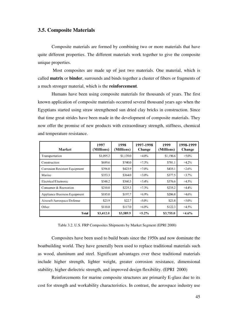
45
3.5. Composite Materials
Composite materials are formed by combining two or more materials that have
quite different properties. The different materials work together to give the composite
unique properties.
Most composites are made up of just two materials. One material, which is
called matrix or binder, surrounds and binds together a cluster of fibers or fragments of
a much stronger material, which is the reinforcement.
Humans have been using composite materials for thousands of years. The first
known application of composite materials occurred several thousand years ago when the
Egyptians started using straw strengthened sun dried clay bricks in construction. Since
that time great strides have been made in the development of composite materials. They
now offer the promise of new products with extraordinary strength, stiffness, chemical
and temperature resistance.
Table 3.2. U.S. FRP Composites Shipments by Market Segment (EPRI 2000)
Composites have been used to build boats since the 1950s and now dominate the
boatbuilding world. They have generally been used to replace traditional materials such
as wood, aluminum and steel. Significant advantages over these traditional materials
include higher strength, lighter weight, greater corrosion resistance, dimensional
stability, higher dielectric strength, and improved design flexibility. (EPRI 2000)
Reinforcements for marine composite structures are primarily E-glass due to its
cost for strength and workability characteristics. In contrast, the aerospace industry use

46
carbon fiber. In general, carbon, aramid fibers and other specialty reinforcements are
used in the marine field where structures are highly engineered for optimum efficiency.
Materials form an integral part of the way composite structures perform.
Because creating a structural material from diverse constituent compounds, material
science concepts are essential to the understanding of how structural composites
behave. Composite materials can be divided to three main part:
· Reinforcements;
· Resins; and
· Core Materials.
3.5.1. Reinforcement Materials
The role of the reinforcement in a composite material is fundamentally one of
increasing the mechanical properties of the neat resin system.
All of the different fibers used in composites have different properties and so
affect the properties of the composite in different ways. However, individual fibers or
fiber bundles can only be used on their own in a few processes such as filament
winding. For most other applications, the fibers need to be arranged into some form of
sheet, known as a fabric, to make handling possible. Different ways for assembling
fibers into sheets and the variety of fiber orientations possible lead to there being many
different types of fabrics, each of which has its own characteristics.
Glass fibers: Glass fibers account for over 90% of the fibers used in reinforced
plastics because they are inexpensive to produce and have relatively good strength to
weight characteristics. Additionally, glass fibers exhibit good chemical resistance and
processability.
By blending quarry products (sand, kaolin, limestone, colemanite) at 1,600C,
liquid glass is formed. The liquid is passed through micro-fine bushings and
simultaneously cooled to produce glass fiber filaments. WEB_17 (2004)
The filaments are drawn together into a strand or roving and coated with a "size"
to provide filament cohesion and protect the glass from abrasion. By variation of the
"recipe", different types of glass can be produced. The types used for structural
reinforcements are as follows:

47
a. E-glass (electrical) - lower alkali content and stronger than A glass (alkali).
Good tensile and compressive strength and stiffness, good electrical properties and
relatively low cost, but impact resistance relatively poor.
b. C-glass (chemical) - best resistance to chemical attack. Mainly used in the
form of surface tissue in the outer layer of laminates used in chemical and water pipes
and tanks.
c. R, S or T-glass – manufacturers trade names for equivalent fibers having
higher tensile strength and modulus than E glass, with better wet strength retention.
Developed for aerospace and defense industries, and used in some hard ballistic armour
applications.
The excellent tensile strength of glass fibers, however, may deteriorate when
loads are applied for long periods of time. Continuous glass fibers are formed by
extruding molten glass to filament diameters between 5 and 25 micrometers. Table 3.3
depicts the designations of fiber diameters commonly used in the FRP industry.
Table 3.3. Glass Fiber Diameter Designations (Greene 2004)
Polymer Fibers: The most common aramid fiber is Kevlar ® developed by
DuPont. This is the predominant organic reinforcing fiber, whose use dates to the early
1970s as a replacement for steel belting in tires. The outstanding features of aramids are
low weight, high tensile strength and modulus, impact and fatigue resistance, and
weaveability. Compressive performance of aramids is not as good as glass, as they show
nonlinear ductile behavior at low strain values. Water absorption of un-impregnated
Kevlar ® 49 is greater than other reinforcements, although ultra-high modulus Kevlar ®
149 absorbs almost two thirds less than Kevlar ® 49. The unique characteristics of
aramids can best be exploited if appropriate weave style and handling techniques are
used.

48
Figure 3.1. Carbon fiber. WEB_9 (2004)
Allied Corporation developed a high strength/modulus extended chain
polyethylene fiber called Spectra ® that was introduced in 1985. Room temperature
specific mechanical properties of Spectra ® are slightly better than Kevlar ® ,
although performance at elevated temperatures falls off. Chemical and wear
resistance data is superior to the aramids.
Table 3.4. Mechanical Properties of Reinforcement Fibers (Greene 2004)
Polyester and nylon thermoplastic fibers have recently been introduced to the
marine industry as primary reinforcements and in a hybrid arrangement with fiberglass.
Allied Corporation has developed a fiber called COMPET ® , which is the product of
applying a finish to PET fibers that enhances matrix adhesion properties. Hoechst-
Celanese manufactures a product called Treveria ® , which is a heat treated polyester
fiber fabric designed as a “bulking” material and as a gel coat barrier to reduce “print-
through.” Although polyester fibers have fairly high strengths, their stiffness is
considerably below that of glass. Other attractive features include low density,
reasonable cost, good impact and fatigue resistance, and potential for vibration damping
and blister resistance.
Carbon Fibers: The terms “carbon” and “graphite” fibers are typically used
interchangeably, although graphite technically refers to fibers that are greater than 99%
carbon composition versus 93 to 95% for PAN-base fibers. All continuous carbon fibers
produced to date are made from organic precursors, which in addition to PAN

49
(polyacrylonitrile), include rayon and pitches, with the latter two generally used for low
modulus fibers.
Carbon fibers offer the highest strength and stiffness of all commonly used
reinforcement fibers. The fibers are not subject to stress rupture or stress corrosion, as
with glass and aramids. High temperature performance is particularly outstanding. The
major drawback to he PAN-base fibers is their relative cost, which is a function of high
precursor costs and an energy intensive manufacturing process. Table 3.4 shows some
comparative fiber performance data.
%0 %10 %20 %30 %40 %50 %60 %70 %80 %90
E-Glass for Hulls .
E-Glass for Decks .
E-Glass for Parts .
Carbon Fiber for Hulls .
Carbon Fiber for Decks .
Carbon Fiber Parts .
Kevlar for Hulls .
Kevlar for Decks .
Kevlar for Parts .
Hybrids for Hulls .
Hybrids for Decks .
Hybrids for Parts .
Thermoplastic for Hulls .
Thermoplastic for Decks .
Thermoplastic for Parts .
Figure 3.2. Marine Industry Reinforcement Material Use (Greene 2004)
Hybrid Fabrics: The term hybrid refers to a fabric that has more than one type
of structural fiber in its construction. In a multi-layer laminate if the properties of more
than one type of fiber are required, then it would be possible to provide this with two
fabrics, each containing the fiber type needed. However, if low weight or extremely thin
laminates are required, a hybrid fabric will allow the two fibers to be presented in just
one layer of fabric instead of two. It would be possible in a woven hybrid to have one
fiber running in the weft direction and the second fiber running in the warp direction,
but it is more common to find alternating threads of each fiber in each warp/weft

50
direction. Al-though hybrids are most commonly found in 0/90 woven fabrics, the
principle is also used in 0/90 stitched, unidirectional and multiaxial fabrics. The most
usual hybrid combinations are:
Carbon / Aramid - The high impact resistance and tensile strength of the aramid
fiber combines with high the compressive and tensile strength of carbon. Both fibers
have low density but relatively high cost.
Aramid / Glass - The low density, high impact resistance and tensile strength of
aramid fiber combines with the good compressive and tensile strength of glass, coupled
with its lower cost.
Carbon / Glass - Carbon fiber contributes high tensile compressive strength and
stiffness and reduces the density, while glass reduces the cost.
3.5.2. Reinforcement Construction
Reinforcement materials are combined with resin systems in a variety of forms
to create structural laminates. The percent of manufacturers using various reinforcement
styles is represented in Figure 3.5. Table 3.5 provides definitions for the various forms
of reinforcement materials. Some of the lower strength non-continuous configurations
are limited to fiberglass due to processing and economic considerations.
Table 3.5. Description of Various Forms of Reinforcements (Greene 2004)

51
Figure 3.3. Reinforcement Fabric Construction Variations (Greene 2004)
Wovens: Woven composite reinforcements generally fall into the category of
cloth or woven roving. Their use in marine construction is limited to small parts and
repairs. Particular weave patterns include plain weave, which is the most highly
interlaced; basket weave, which has warp and fill yarns that are paired up; and satin
weaves, which exhibit a minimum of interlacing. The satin weaves are produced in
standard four-, five- or eight-harness configurations, which exhibit a corresponding
increase in resistance to shear distortion (easily draped). Figure 3.3 shows some
commercially available weave patterns.
Woven roving reinforcements consist of flattened bundles of continuous strands
in a plain weave pattern with slightly more material in the warp direction. This is the
most common type of reinforcement used for large marine structures because it is
available in fairly heavy weights (24 ounces per square yard is the most common),
which enable a rapid build up of thickness. Also, directional strength characteristics are
possible with a material that is still fairly drapable. Impact resistance is enhanced
because the fibers are continuously woven.

52
Figure 3.4. Comparison of Conventional Woven Roving and a Knitted Biaxial Fabric Showing
Theoretical Kink Stress in Woven Roving (Greene 2004)
Knits: Knitted reinforcement fabrics were first introduced by Knytex ® in 1975
to provide greater strength and stiffness per unit thickness as compared to woven
rovings. A knitted reinforcement is constructed using a combination of unidirectional
reinforcements that are stitched together with a nonstructural synthetic such as
polyester. A layer of mat may also be incorporated into the construction. The process
provides the advantage of having the reinforcing fiber lying flat versus the crimped
orientation of woven roving fiber. Additionally, reinforcements can be oriented along
any combination of axes. Superior glass to resin ratios are also achieved, which makes
overall laminate costs competitive with traditional materials. Figure 3.4 shows a
comparison of woven roving and knitted construction.
Omnidirectional: Omnidirectional reinforcements can be applied during hand
lay-up as prefabricated mat or via the spray-up process as chopped strand mat. Chopped
strand mat consists of randomly oriented glass fiber strands that are held together with a
soluble resinous binder. Continuous strand mat is similar to chopped strand mat, except
that the fiber is continuous and laid down in a swirl pattern. Both hand lay-up and
spray-up methods produce plies with equal properties along the x and y-axes and good
interlaminar shear strength. This is a very economical way to build up thickness,
especially with complex molds. Mechanical properties are less than other
reinforcements.
Unidirectional: Pure unidirectional construction implies no structural
reinforcement in the fill direction. Ultra high strength/modulus material, such as carbon

53
fiber, is sometimes used in this form due to its high cost and specificity of application.
Material widths are generally limited due to the difficulty of handling and wet-out.
Anchor Reinforcements has recently introduced a line of unidirectional that are held
together with a thermoplastic web binder that is compatible with thermoset resin
systems. The company claims that the material is easier to handle and cut than
traditional pure unidirectional material. Typical applications for unidirectionals include
stem and centerline stiffening as well as the tops of stiffeners. Entire hulls are fabricated
from unidirectional reinforcements when an ultra high performance laminate is desired.
%0 %10 %20 %30 %40 %50 %60 %70
Chopped Strand Mat for Hulls .
Chopped Strand Mat for Decks .
Chopped Strand Mat for Parts .
Woven Roving for Hulls .
Woven Roving for Decks .
Woven Roving Parts .
Cloth for Hulls .
Cloth for Decks .
Cloth for Parts .
Knits for Hulls .
Knits for Decks .
Knits for Parts .
Unidirectional for Hulls .
Unidirectional for Decks .
Unidirectional for Parts .
Figure 3.5. Marine Industry Reinforcement Style Use (Greene 2004)
3.5.3. Resins
For the matrix, many modern composites use thermosetting or thermosoftening
plastics. The plastics are polymers that hold the reinforcement together and help to
determine the physical properties of the end product. The percent of manufacturers
using various resin systems is represented in Figure 3.6.

54
Polyester: Polyester resins are the most widely used resin systems, particularly
in the marine industry. By far the majority of dinghies, yachts and workboats built in
composites make use of this resin system.
Polyester resins are the simplest, most economical resin systems that are easiest
to use and show good chemical resistance.
Most polyesters are air inhibited and will not cure when exposed to air.
Typically, paraffin is added to the resin formulation, which has the effect of sealing the
surface during the cure process. However, the wax film on the surface presents a
problem for secondary bonding or finishing and must be physically removed. Non-air
inhibited resins do not present this problem and are therefore, more widely accepted in
the marine industry.
The two basic polyester resins used in the marine industry are orthophthalic and
isophthalic. The ortho resins were the original group of polyesters developed and are
still in widespread use. They have somewhat limited thermal stability, chemical
resistance, and processability characteristics. The iso resins generally have better
mechanical properties and show better chemical resistance. Their increased resistance to
water permeation has prompted many builders to use this resin as a gel coat or barrier
coat in marine laminates.
Curing of polyester without the addition of heat is accomplished by adding
accelerator along with the catalyst. Gel times can be carefully controlled by modifying
formulations to match ambient temperature conditions and laminate thickness.The
following combinations of curing additives are most common for use with polyesters:
Table 3.6. Polyester Resin Catalyst and Accelerator Combinations (Scott 1996)
Other resin additives can modify the viscosity of the resin if vertical or overhead
surfaces are being laminated. This effect is achieved through the addition of silicon
dioxide, in which case the resin is called thixotropic. Various other fillers are used to
reduce resin shrinkage upon cure, a useful feature for gel coats.

55
Vinyl Ester: Vinyl ester resins are unsaturated resins prepared by the reaction of
a monofunctional unsaturated acid, such as methacrylic or acrylic, with a bisphenol
diepoxide. The resulting polymer is mixed with an unsaturated monomer, such as
styrene. The handling and performance characteristics of vinyl esters are similar to
polyesters. Some advantages of the vinyl esters, which may justify their higher cost,
include superior corrosion resistance, hydrolytic stability, and excellent physical
properties, such as impact and fatigue resistance. It has been shown that a 20 to 60 mil
layer with a vinyl ester resin matrix can provide an excellent permeation barrier to resist
blistering in marine laminates.
Table 3.7. Comparative Data for Some Thermoset Resin Systems (Greene 2004)
Epoxy: Epoxy resins are a broad family of materials that contain a reactive
functional group in their molecular structure. Epoxy resins show the best performance
characteristics of all the resins used in the marine industry. Aerospace applications use
epoxy almost exclusively, except when high temperature performance is critical. The
high cost of epoxies and handling difficulties have limited their use for large marine
structures. Table 3.7. shows some comparative data for various thermoset resin systems.
Thermoplastics: Thermoplastics have one- or two-dimensional molecular
structures, as opposed to three-dimensional structures for thermosets. The
thermoplastics generally come in the form of molding compounds that soften at high
temperatures. Polyethylene, polystyrene, polypropylene, polyamides and nylon are
examples of thermoplastics. Their use in the marine industry has generally been limited
to small boats and recreational items. Reinforced thermoplastic materials have recently

56
been investigated for the large scale production of structural components. Some
attractive features include no exotherm upon cure, which has plagued filament winding
of extremely thick sections with thermosets, and enhanced damage tolerance.
Processability and strengths compatible with reinforcement material are key areas
currently under development.
%0 %10 %20 %30 %40 %50
Orthopolyester for Hulls .
Orthopolyester for Decks .
Orthopolyester for Parts .
Isopolyester for Hulls .
Isopolyester for Decks .
Isopolyester for Parts .
Vinyl Ester for Hulls .
Vinyl Ester for Decks .
Vinyl Ester Parts .
Epoxy for Hulls .
Epoxy for Decks .
Epoxy for Parts .
Figure 3.6. Marine Industry Resin System Use (Greene 2004)
3.5.4. Core Materials
The purpose of a core in a composite laminate is to increase the laminate’s
stiffness by effectively ‘thickening’ it with a low-density core material. This can
provide a dramatic increase in stiffness for very little additional weight.
Balsa: The most commonly used wood core is end-grain balsa. Balsa wood
cores first appeared in the 1940’s in flying boat hulls, which were aluminium skinned
and balsa-cored to withstand the repeated impact of landing on water. This performance
led the marine industry to begin using end-grain balsa as a core material in FRP
construction. Apart from its high compressive properties, its advantages include being a
good thermal insulator offering good acoustic absorption.
The material will not deform when heated and acts as an insulating and ablative
layer in a fire, with the core charring slowly, allowing the non-exposed skin to remain

57
structurally sound. It also offers positive flotation and is easily worked with simple tools
and equipment. Balsa core is available as contoured end-grain sheets 3 to 50mm thick
on a backing fabric, and rigid end-grain sheets up to 100mm thick. These sheets can be
provided ready resin-coated for vacuum-bagging, prepreg or pressure-based
manufacturing processes such as RTM. One of the disadvantages of balsa is its high
minimum density, with 100kg/m3 being a typical minimum.
This problem is exacerbated by the fact that balsa can absorb large quantities
of resin during lamination, although pre-sealing the foam can reduce this. Its use is
therefore normally restricted to projects where optimum weight saving is not required
or in locally highly stressed areas.
Figure 3.7. Balsa Cell Geometry with A =Average Cell Length = .025"; B = Average Cell Diameter =
.00126"; C = Average CellWall Thickness = .00006". WEB_3 (2004)
Thermoset Foams: Foamed plastics such as cellular cellulose acetate (CCA),
polystyrene, and polyurethane are very light (about 2 lbs/ft 3) and resist water, fungi
and decay. These materials have very low mechanical properties and polystyrene will be
attacked by polyester resin. These foams will not conform to complex curves. Use is
generally limited to buoyancy rather than structural applications. Polyurethane is often
foamed in-place when used as a buoyancy material.
Syntactic Foams: Syntactic foams are made by mixing hollow microspheres of
glass, epoxy and phenolic into fluid resin with additives and curing agents to form a
moldable, curable, lightweight fluid mass. Omega Chemical has introduced a sprayable
syntactic core material called SprayCore TM . The company claims that thicknesses of
3/8" can be achieved at densities between 30 and 43 lbs/ft 3 . The system is being
marketed as a replacement for core fabrics with superior physical properties.

58
Cross Linked PVC Foams: Polyvinyl foam cores are manufactured by
combining a polyvinyl copolymer with stabilizers, plasticizers, cross-linking
compounds and blowing agents. The mixture is heated under pressure to initiate the
cross-linking reaction and then submerged in hot water tanks to expand to the desired
density. The resulting material is thermoplastic, enabling the material to conform to
compound curves of a hull. PVC foams have almost exclusively replaced urethane
foams as a structural core material, except in configurations where the foam is “blown”
in place. A number of manufacturers market cross-linked PVC products to the marine
industry in sheet form with densities ranging from 2 to 12 pounds per ft 3.
Linear PVC Foam: Airex ® and Core-Cell ® are examples of linear PVC foam
core produced for the marine industry. Unique mechanical properties are a result of a
non-connected molecular structure, which allows significant displacements before
failure. In comparison to the cross linked (non-linear) PVCs, static properties will be
less favorable and impact will be better.
Honeycomb: Various types of manufactured honeycomb cores are used
extensively in the aerospace industry. Constituent materials include aluminum, phenolic
resin impregnated fiberglass, polypropylene and aramid fiber phenolic treated paper.
Although the fabrication of extremely lightweight panels is possible with honeycomb
cores, applications in a marine environment are limited due to the difficulty of bonding
to complex face geometries and the potential for significant water absorption. The Navy
has had some corrosion problems when an aluminum honeycomb core was used for
ASROC housings. Data on a Nomex ® phenolic resin honeycomb product is presented
in Table 3.8. (Greene 2004)

59
Table 3.8. Comparative Data for Some Sandwich Core Materials (Greene 2004)
PMI Foam: Rohm Tech, Inc. markets a polymrthacrylimide (PMI) foam for
composite construction called Rohacell ® . The material requires minimum laminating
pressures to develop good peel strength. The most attractive feature of this material is
its ability to withstand curing temperatures in excess of 350°F, which makes it attractive
for use with prepreg reinforcements. Table 3.8 summarizes the physical properties of a
common grade of Rohacell ® .
FRP Planking: Seemann Fiberglass, Inc. developed a product called C-Flex ®
in 1973 to help amateurs build a cost effective one-off hull. The planking consists of
rigid fiberglass rods held together with unsaturated strands of continuous fiberglass
rovings and a light fiberglass cloth. The self-supporting material will conform to
compound curves. Typical application involves a set of male frames as a form. The
planking has more rigidity than PVC foam sheets, which eliminates the need for
extensive longitudinal stringers on the male mold.

60
%0 %5 %10 %15 %20 %25 %30 %35 %40 %45 %50
Balsa for Hulls .
Balsa for Decks .
Balsa for Parts .
Linear PVC for Hulls .
Linear PVC for Decks .
Linear PVC Parts .
Cross-Linked PVC for Hulls .
Cross-Linked PVC for Decks .
Cross-Linked PVC for Parts .
“Bulker” Material for Hulls .
“Bulker” Material for Decks .
“Bulker” Material for Parts .
Urethane Foam for Hulls .
Urethane Foam for Decks .
Urethane Foam for Parts .
Figure 3.8. Marine Industry Core Material Use (Greene 2004)
Core Fabrics: Various natural and synthetic materials are used to manufacture
products to build up laminate thickness economically. One such product that is popular
in the marine industry is Firet Coremat, a spun-bound polyester produced by Lantor.
Hoechst Celanese has recently introduced a product called Trevira , which is a
continuous filament polyester. The continuous fibers seem to produce a fabric with
superior mechanical properties. Ozite produces a core fabric called Compozitex TM
from inorganic vitreous fibers. The manufacturer claims that a unique manufacturing
process creates a mechanical fiber lock within the fabric. Although many manufacturers
have had much success with such materials in the center of the laminate, the use of a
Nonstructural thick ply near the laminate surface to eliminate print-through requires
engineering forethought. The high modulus, low strength ply can produce premature
cosmetic failures. Other manufacturers have started to produce “bulking” products that
are primarily used to build up laminate thickness.
Plywood: Plywood should also be mentioned as a structural core material,
although fiberglass is generally viewed as merely sheathing when used in conjunction
with plywood. Exceptions to this characterization include local reinforcements in way
of hardware installations where plywood replaces a lighter density core to improve

61
compression properties of the laminate. Plywood is also sometimes used as a form for
longitudinals, especially in way of engine mounts. Concern over the continued
propensity for wood to absorb moisture in a maritime environment, which can cause
swelling and subsequent delamination, has precipitated a decline in the use of wood in
conjunction with FRP. The uneven surface of plywood can make it a poor bonding
surface. Also, the low strength and low strain characteristics of plywood can lead to
premature failures when used as a core with thin skins. The technique of laminating
numerous thin plies of wood developed by the Gougeon Brothers and known as wood
epoxy saturation technique (WEST ® System) eliminates many of the shortcomings
involved with using wood in composite structures. (Greene 2004)
3.6. Comparison of the Materials used in Boat Construction
The most important thing for boat design and production is to determine the
material, which have the different advantage and options for designer.
The intended use of the vessel affects the material choice because that will set
the performance expected, the level of maltreatment to which it will be subjected, the
standard of finish required and the amount of maintenance, which is acceptable. A boat
intended for commercial fishing or cargo work will have very different needs from one,
which is to compete in the high-class charter fleets.
In the size range, 10m to 30m,the principal materials are wood, steel, fiber-
reinforced plastic (FRP), ferrocement and aluminum.
In this range, wood is in general lighter than steel, but because of the greater
thickness of the hull construction, requires a larger hull for the same internal capacity.
Ferro cement will in general be heavier than steel if near equivalent strengths are
to be obtained. Although there can be a slight reduction in size for equivalent internal
capacity, the increased weight should be allowed for in the design calculation. Care
must be taken in weight control and the economic consequences of increased weight
balanced against such factors as lower initial cost and reduced maintenance.
Aluminum construction is the highest in first cost of the materials being
considered for boats but this initial cost can be offset by potential savings in operational
costs and maintenance over the lifetime of the vessel.

62
FRP is the most common material in modern boatbuilding. Properly done, it
produces sound boats capable of safely travelling to almost any corner of the world.
When a mould is available for the chosen design, the hull, deck and available modules
can be produced with a minimum of effort and in a very short time.
3.6.1. Comparison of mechanical characteristics
To get a correct insight into the qualities of various materials; tensile strength,
bending strength and rigidity must be investigated separately.
Figure 3.9. Beam submitted to tensile force P Figure 3.10. Beam submitted to bending force P (Verweij 1978) (Verweij 1978)
Figure 3.11. Wooden plate supported at Figure 3.12. Wooden plate supported at right angle to grain.(Verweij 1978) parallel to grain. (Verweij 1978)
• Criterion for tensile strength
If a beam in figure 3.9. with unit width and thickness H is now subjected to
tensile force Ft, then the tensile stress σσσσt equals Ft/ H. Beams of different materials are
of equal weight of their thickness, H, varies in inverse ratio to their specific gravity.
Therefore, the maximum tensile force which beams of equal weight but of different
materials can withstand is dependent on the ratio: σσσσt / �
• Criterion for bending strength
The beam in figure 3.10 with unit width and thickness H is now subjected to a
bending force Fb. This results in a bending stress:
Direction of grain
Direction of grain

63
σσσσ b =M ; M= ¼ Fbl = bending moment
W= 1/6 H² = modulus of section
The maximum bending force which beam of equal weight can withstand is
dependent on the ratio: σσσσb / �²
• Criterion for rigidity
Apart from strength, we must consider stiffness. It may happen that a beam
(figure 3.10.) bends so much under a force Fb that the deflection, a, surpasses
acceptable values, although the bending stress σb may stay within normal limits.
Therefore, stiffness and strength must be dealt with separately. The deflection, a,
depends on the ratio Fb/ EI where E= modulus elasticity, and I= moment of inertia=
1/12 . h³
The bending force which causes beams of equal weight to deflect equally
depends on the ratio: E/ �³
• Summary of criterion
For a given weight:
Tensile strength proportional to: σσσσt / �
Bending strength proportional to: σσσσt / �²
Rigidity proportional to: E / �³
1. Comparison of FRP with steel and light alloy as regards strength and rigidity
In table 3.9 and table 3.10, FRP, both with mat and with woven roving as
reinforcement, is compared with steel and light alloy on the basis of equal weight and
using the three criteria found above. With FRP mat as a basis, it follows:
• FRP-woven roving is stronger than aluminum, FRP-mat and steel.
• FRP-woven roving is more rigid than FRP-mat and steel.
• Aluminum is more rigid than FRP-woven roving, FRP-mat and steel.

64
Table 3.9. FRP versus steel and aluminum as regard strength and stiffness-1. (Verweij 1978)
Table 3.10. FRP versus steel and aluminium as regard strength and stiffness-2. (Verweij 1978)
2. Comparison of FRP with wood as regards strength and rigidity
Whereas comparison of the mechanical qualities of FRP with those of steel and
aluminium was rather simple, a comparison of FRP with wood is more difficult. This is
because of the followings:
• Variations in mechanical qualities of various samples of same wood can
differ greatly
• The mechanical qualities of wood are greatly affected by the moisture
content
• A wooden boat is not a homogenous structure, but consist of great
number of parts held together by frames and fastenings. These fastenings
cause weak spot in the structure

65
Table 3.11. FRP versus wood as regard strength and stiffness-1. (Verweij 1978)
Table 3.12. FRP versus wood as regard strength and stiffness-2. (Verweij 1978)
Therefore, a comparison on the basis of laboratory-selected samples of wood
bears little relation to the characteristics of the complete wood enstructure in the boat.
Nevertheless, an attempt is made to compare FRP-mat and FRP-woven roving with oak,
teak, fir and pitch pine (table 3.11. and table 3.12.). The mechanical qualities of the
wood are those for wet wood, taken along the direction of the grain, i.e. for wooden
beams, supported and loaded as in figure 3.11.
Conclusion, on the basis of equal weight, wood (in wet condition tested as figure
3.11.) is much more rigid than FRP-mat. However, FRP-woven is stronger than wood.

66
3. Comparison over practical experience of FRP and other materials
The comparison of the materials as given in table 3.9.-3.14. is based on a
comparison of beams out of the different materials.
It is difficult, if not impossible, to compare FRP with wood soley on the basis of
the tables showing mechanical characteristics, but rather with actual experience with
wooden and FRP boats, which have stood up practice, and have been built lighter than
comparable wooden craft and with good result. Some examples may illustrate this.
In many countries, ship’ lifeboats made of FRP have almost completely replaces
former wooden, steel and aluminum boats. These FRP boats are lighter than the others,
yet they are strong enough for their purpose. Only FRP lifeboats have to pass rigorous
tests, amongst these a drop test, illustrated in figure 3.13. It is unthinkable that wooden
lifeboats would survive such treatment.
Figure 3.13. Drop test with FRP lifeboat. (Verweij 1978)
The FRP boat is stronger. In a test report, issued by police authorities after
testing the prototype for some months, it was said:
“….in shallow water, on several occasion sand and stone bottoms were hit and
the boat suffered no damage. Even when running full speed and with the ebb-tide the
boat ran aground on a stone jetty below the water surface which brought the boat to a
sudden stop. The damage done was some scratches on the hull and a dented bilge keel.
Once the boat was jammed between a bigger vessel and a mooring post which led one
to expect that everything would be crushed; however, after the pressure was released,
the boat returned to her old shape. If this had happened to a wooden craft, it would have
been irreparably damaged, whilst a steel boat would been dented severely.”
Another proof of superiority of FRP over wooden boats can be found in the
military field. A great number of armies are replacing or have replaced their wooden

67
storm and assault boats by FRP. These boats can be made not only lighter for the
strength required but have lower maintenance and repair costs. (Verweij 1978)
4. Comparison of FRP sandwich with other materials
When comparing FRP with aluminum, but more especially wood, it was found
that although FRP was stronger, it was less stiff. This can be overcome by adopting a
sandwich-type of construction. The principle of this is illustrated in figure 3.14. The
inner and outer skins are held apart by core of light-weight material. For this, PVC-
foam has been used with success in a great many cases.
• Outer skin 0.3 times core thickness
• Inner skin 0.2 times core thickness
In theory the skins can be much thinner, but they become so vulnerable that they
little practical value.
Figure 3.14. Sandwich FRP (Verweij 1978)
• Influence of mechanical characteristics
For the sandwich in figure 3.14., with facing of woven roving with specific
gravity, 1.6 and PVC-foam core with specific gravity, 0.08, we find an overall specific
gravity of 0.59.
So the sandwich with total thickness 1.5 H has the same weight as a solid FRP
laminate with a thickness =1.5 H x 0.59 / 1.6=0.55 H. When calculating the moment of
resistance and the moment of inertia for both the sandwich and the solid laminate, we
find:
• ratio sandwich: solid of modulus of section: 0.224 H² / 0.05 H² = 4.5
• ratio sandwich: solid moment of inertia: 0.190 H ³ / 0.014 H ³ = 13.6

68
However, the bending strength of the sandwich as well as he modulus of
elasticity are lower than those found for the solid laminate. For the sandwich in question
we find :
6b=15,700 lb/in² (1,100 kg/ cm²)
E= 1,145,000 lb/in² (80,000 kg/ cm²)
Therefore :
• Strength sandwich FRP / strength solid FRP = 4.5 x 15,700 / 31,500 = 2.25
• Rigidity of sandwich FRP / rigidity of solid FRP = 13.6 x 1,145,000 / 1,500,00 =
10.4
Conclusion, from table 3.13 and 3.14, it is clear that FRP sandwich is the best
as regard mechanical qualities.
Table 3.13. FRP versus other materials at equal weight-1. (Verweij 1978)
Table 3.14. FRP versus other materials at equal weight-2. (Verweij 1978)
3.6.2. Comparison of Influence of Weight
In the foregoing great stress has been laid on selecting a construction material
with favourable relation of strength and stiffness for weight. It was found that FRP
fulfils these requirements best. Weight is so important because of the following reasons:
• If a boat is heavy, then much material must be handled during
construction, which increases building costs.
• The handling characteristic of beach-landing craft are mainly governed
by weight of the boat. Above a certain weight limit, it is impossible to
handle a boat alone or with two people. For a given total weight,
therefore, a boat made out of a material with a high strength: weight ratio
can be larger.

69
• It requires less power for the same speed to propel a lighter vessel, and
therefore either speed may be increased or power reduced
On the other hand, it is nor necessary for a boat to heavy in order to be stable
and to have good sea-keeping qualities.
In a report by the Towing Tang in Hamburg (Möckel, 1963, Verweij 1978), it was
clearly proved that in comparing the stability of wooden pilot boats and FRP pilot boats,
the lighter FRP boats were just as stable. Of course, and this is very important, the
designer of FRP boats should take into account the influence on weight of the
construction material, which he selects when determining length, beam, depth and
freeboard as well when designing the lines plan of the boat in question.
3.6.3. Comparison of Impact
All wooden construction boats are rather easily damaged by impact forces; steel
and more especially aluminum get severely dented or even damaged by impact forces.
Steel and aluminum are moreover weakened considerably by notches or scratches. On
the other hand, FRP shows excellent impact resistance, with FRP woven roving by far
the best. Moreover the impact resistance values are only slightly reduced by notches.
This is of great practical value. Not only will a FRP boat be able to withstand rough
treatment, but also a crack once started will not continue easily as is the case with steel
and aluminum.
3.6.4. Comparison of Fatigue
All of the materials mentioned in this part show reduction in strength if
submitted for a prolonged time to alternating or constant forces. Both wood and FRP
show fatigue strength after 10 million cycles of around 25 to 30 per cent of static
strength; aluminium is the same or even less good than FRP. Steel is slightly better in
this respect, since it remains about 40 per cent of its strength.
For FRP sandwich construction, a PVC-foam core may be severely weakened in
case of high temperatures and is especially the case with horizontal surfaces like decks,
when other core materials should be considered.

70
3.6.5. Comparison of Corrosion Resistance
Steel needs continuous and excellent protection to prevent rapid corrosion under
salt-water condition. Some woods, especially those containing acids, such as oak and
Douglas fir, may have a severe corrosive influence on steel.
Aluminium shows quite different result, depending on the type of alloy used.
Some alloys show little or no corrosion in sea-water. However, aluminium remains a
difficult material as regards corrosion and may give quite unexpected results. If wood,
treated with preservatives containing copper, comes into contact with aluminium, this
will lead to rapid corrosion. Also many antifouling paints have a disastrous effect on
aluminium. Ships’ life-boats have corroded completely where supported by leather-
covered chocks.
With the exception of teak, all wood should be protected by proper painting to
prevent rot and decay.
FRP is not affected by sea-water, provided proper raw material of boat-building
quality have been used and have been handled with the necessary knowledge and care.
3.6.6. Comparison of Durability and Maintenance
One of the main advantages of FRP over any other material mentioned above is
that it is durable, if made properly, even if unattended and without maintenance, except
perhaps for a regular coat of antifouling paint.
There are several examples demonstrating this long-term durability. In a report
regarding three U.S. Coast Guard boats (Cobb 1962, Verweij 1978) results of inspection
of these ten-year-old boats were most encouraging. Neither sea-water (heavily polluted
in this case) nor leak oil nor dirt on the inside had had any measurable effect on the
laminate. Especially important was that the maintenance costs for these craft had been
80 per cent less than for comparable steel craft.
The U.S. Buships report (Graner 1960, Verweij 1978) on the superstructure of a
U.S. submarine. After having been used for more than five years, the flexural strength
was still 88 per cent and the flexural modulus 91 per cent of the original values. There
was no change in hardness.

71
Table 3.15. Heat conductivity. (Verweij 1978)
3.6.7. Comparison of Thermal Insulation
For nearly all craft, proper thermal insulation can be an important requirement.
Table 3.15 shows again that FRP, especially FRP sandwich, has excellent qualities. An
illustration of the heat-insulating qualities is given in the aforementioned report (Cobb,
1962). During a serious tanker fire in the port of Houston, a FRP and a steel patrol boat
were despatched to the scene of the accident. The crew of the FRP boat were able to
operate closer to the intense heat and for longer period than those on the steel boat,
because of the low conductivity of the fibreglass boat. While the topside paint was
scorched, the laminate did not ignite nor was it damaged.
3.6.8. Comparison of Cost
For a boat, especially if made sandwich, the excellent thermal insulation of FRP
will make it possible to reduce drastically or leave out extra thermal insulation layers.
This influences building costs favorably.
Prices of material may vary considerably according to location. Current prices in
the Netherlands are given in table 3.16.
Table 3.16. Prices of materials in the Netherlands (Verweij 1978)

72
Taking into account, however, the differences in strength and rigidy of actual
vessels, wooden construction is about 40 per cent and steel 100 per cent heavier than
FRP. Table 3.17 gives an indication of the actual material costs for boats of different
material.
Table 3.17. Actual material costs for boats of different materials. (Verweij 1978)
3.6.9. Comparison of Labor Costs
The influence of labor costs on the total price of a vessel is great. Moreover, it is
to be expected that this influence will increase, since almost universally they are
increasing more rapidly than the cost of materials. With FRP, especially, the labor costs
are influenced by several factors:
• Number of boats required
• Type of glass reinforcement
• Solid laminate, sandwich, or both
• Degree of mechanization
• Construction details
• Finish required
In many cases the designer can have a great influence on the actual labor costs
and it requires much experience to design optimum boats in this respect. In view of the
great number of variables, it is impossible to make a valid comparison of labor costs of
FRP with other materials.
More detailed comparison between the materials over cost estimates can be
found in appendix A.
Conclusion, material costs of FRP are by no means excessive. Labor costs of
FRP vary greatly depending on design and the number of boats required. Provided they
can be made in sufficient quantity, experience in different countries indicates that in
many cases FRP boats are not more expensive, and often cheaper, than boats of other
materials.

73
3.6.10. Summary of Comparison
The potential advantages of FRP over other materials for small craft
construction are as follows:
Resistance to the marine environment: FRP does not corrode, rot or otherwise
deteriorate when exposed for extended periods o salt air or water. It is equally
unaffected by fuels or pollutants often found in rivers and harbors. Conventional FRP
will become fouled with grass and barnacles as readily as wood or metal and requires
antifouling bottom paint in salt or brackish water.
Light weight: With proper design and control in the shop, FRP marine
structures can be fabricated that are about one-half the weight to equivalent steel or
wood structures and about equal in weight to equivalent aluminum structures.
High Strength: The inherent of FRP is quite high relative to its weight, and
long exposure to a marine environment has little effect on its properties.
Seamless Construction: FRP hulls are generally fabricated as a one-piece leak
proof molding without seam or laps.
Chemically Inert: FRP is not affected by salt water or most chemicals
associated with a marine environment, and is not susceptible to electrolysis.
Ability to Orient Fiber Strength: The nature of FRP reinforcement permits the
glass fibers to be oriented in the direction of maximum stress, providing the designer
with the ability to economically optimize strength-weight relationship to greater extent
than with metals.
Ability to Mold Complex Shapes: FRP materials can be molded into a wide
variety of complex shapes with relative ease and economy.
Flexibility: The low modulus of elasticity of FRP is beneficial in absorbing
energy from impact loads such as slamming. However, this flexibility can also be a
design constraint where deflections are critical.
Competitive Cost: Although the cost per pound of FRP materials is usually
considerably higher than wood or steel, the over-all cost of an FRP boat is usually only
slightly higher than the equivalent wood or steel hull providing the number of hulls
being built in FRP are sufficient to amortize the cost of molds and other tooling. Higher
costs are to be expected for prototype or one of a kind FRP hulls. FRP is generally
competitive with, or slightly cheaper than, aluminum construction for high-volume
production of larger boats, and may be nearly competitive for limited production.

74
Ability to Mold in Color: The plastic used to form FRP laminates can be
provided in wide variety of colors which eliminate the need to paint the boat for many
seasons. Eventually, however, the color may fade or chalk, requiring cosmetic painting.
Repairs: FRP structures are relatively easy to repair.
Low Maintenance: The non-corrosive nature of FRP generally results in much
lower hull maintenance for smaller craft. The corresponding savings for larger hulls
may be less since antifouling painting is required at the same intervals as with hulls of
other materials, and painting of topsides will eventually be required to cover up scrapes,
gouges and color fading.
Durability: Surveys of U.S. Navy and U.S. Coast Guard small boats and
pleasure craft indicate no degradation in laminate properties after as long as 20 year
service. With proper maintenance and reasonable care FRP boats would appear to have
an indefinite life.
These advantages are offset by a number of potential problems, which must be
considered in designing FRP boats, including the following:
Stiffness: The modulus of elasticity of conventional FRP laminates is usually
less than 2x 10³x10³ PSI, compared to 30 x 10³x10³ for steel and 10x 10³x10³ PSI for
aluminum. The use of unidirectional FRP laminates with greater percentage of the glass
oriented in the direction of the load or higher strength glass/ carbon composites can
increase the modulus to about 4 to 6 x 10³x10³ PSI, but FRP is still at a disadvantage in
deflection-critical application.
Hull Strength: Although the basic short-term strength of FRP is quite
satisfactory, its relative fatigue strength is somewhat lower than metals, which must be
consider in selecting design loads and safety factors. In addition, the notch toughness of
FRP structures must be evaluated to determine the problems associated with stress
concentrations such as at hatch corners, endings of stiffeners or decks, and other
discontinuities. The low buckling strength of FRP also warrants consideration in
evaluating the basic structural concepts.
Creep: FRP has a tendency to creep if subjected to long-term loading and if the
laminate stresses are high, though this is not a problem for normal boat structures.
Vibration: The low modulus of elasticity of FRP may lead to problems with
structural vibrations, particularly in way of reciprocating machinery and propellers, if
adequate stiffness is not provided.

75
Abrasion: The abrasion resistance of FRP is less than that of metals, though
better than wood, and necessitates the use of bumpers or chafing plates in areas where
abrasive loads might occur.
Vulnerability to Fire: The conventional FRP laminate is fabricated with a type
of resin, which is flammable and will support combustion with about the same intensity
and flame-spread rate as plywood. There are fire-retardant types available, which are
self-extinguishing after removal of the source of flame, though they are still
combustible to some degree, and the laminates rapidly lose strength at high
temperatures. The fire-retardant resins also generate toxic fumes in the presence of fire.
However, FRP has very good fire containment capabilities and, if properly insulated or
protected can perform satisfactorily in a fire environment. (Scott 1996)
FRP is the dominant material in small boat construction and this indicates that
its advantages greatly overshadow the disadvantages. The extensive experience gained
in designing, building and operating FRP boats over the past 50 years has produced
satisfactory and economical means of designing around the material’s characteristic.

76
CHAPTER 4
MANUFACTURING PROCCESS AND CONSTRUCTION
TECHNIQUES OF FRP RECREATIONAL BOATS
A wide range of different processes have developed for molding of composites
parts ranging from very simple manual processes such as hand lay to highly
industrialized processes such as SMC (Sheet Molding Compound) molding. Each
process has its own particular benefits and limitations making it applicable for particular
applications. The choice of process is important in order to achieve the required
technical performance at an economic cost.
The main technical factors that govern the choice of process are the size and
shape of the part, the mechanical and environmental performance and aesthetics. The
main economic factor is the number of identical parts required or run length.
This chapter will focus on the production techniques of FRP recreational boats
both conventional such as hand lamination and spray lamination and more industrialized
techniques such as vacuum bag, resin transfer molding and SMC, etc. Beside production
techniques, mold building and equipments used in construction will be mentioned.
4.1. History of Boat Construction
FRP was used initially for boat construction shortly after World War II. Among
the first were a series of 28 foot U.S. Navy personnel boats. Since then, the navy
continued to rely heavily on FRP for construction of thousand of small boats from 12
feet to 50 feet in length including landing craft, utility and personnel boats, line
handling boat is the 31 foot PBR River Patrol Boat, which saw extensive service in
Southeast Asia.
The U.S. Coast Guard has employed FRP for the construction of a wide variety
of utility and patrol boats up to 40 feet in length. Examination of early FRP 40 footer in
1972 which had seen nearly 20 years of continuous service showed her hull laminate to
be in excellent condition, with no apparent degradation in structural properties.

77
After successful experiences of FRP boats in navy and coast guard, FRP started
to appear in civil boats such as runabout and sailboats. Today vast majority of
powerboats and sailboats built in most country are fiberglass construction
The highly competitive nature of the pleasure boat industry result in numerous
design and production innovations to improve the performance and reduce the cost of
the fiberglass structures, including the concept of a drop-in molded FRP hull liner into
which berths, galley components and decorative surface are integrally molded. This
concept greatly reduces the time and cost of fitting out the boat. Other innovations
included molded-in buoyancy foam and non-skid deck patterns and one-piece molded
bottom grillages. The ability to easily mold complex shapes permitted the economic
development of a number of new hull forms such as the cathedral and trihedral hulls,
which would be extremely difficult to shape in either wood or metal.
The introduction of carbon, graphite, aramid and other high performance fibers
developed initially for the aerospace industry. These developments have opened up new
opportunities for composite structures. Many offshore racing powerboats and high
performance sailboats incorporate such materials in the hull and spars to achieve
strength to weight rations not possible with other materials.
The development of large fiberglass fishing trawlers began in 1960 in South
Africa with construction of series of 63-foot long pilchard trawlers. The success of
vessels led to parallel developments in the United States. The first such vessel was the
72 foot trawler R.C. BRENT, launched in Florida in 1968. This led to several builders
marketing FRP shrimp trawlers about 75 feet long. Service experience with these boats
is excellent. The largest FRP fishing trawler in series production was a 93 foot purse
seiner being built in Peru. Early studies indicate the feasibility of FRP trawlers up to
110 feet long and there is no reason to believe that this is the upper limit on size.
The development of FRP minesweepers was begun simultaneously by the
United States and British Navies in the early 1960’s. The non-magnetic nature of FRP
makes it an ideal material for such a vessel, since it is both lighter and lower in life
cycle cost than conventional wood construction. Initial U.S. Navy studies, indicated the
feasibility of building FRP minesweepers up to about 190 feet long and led to the
construction of a full scale midship section which was tested for acoustic characteristics
and shock resistance in 1970. The British studies and tests were sufficiently successful
that a prototype 153-foot FRP mine hunter was completed in January 1972. This was
followed by the HUNT and SANDOWN classes for the Royal Navy, and the Italian

78
LERICI and GAETA classes. The U.S. Navy’s OSPREY class minehunter, derived
from the GAETA class, is 188 feet long and displaces 890 tons, and is the largest FRP
ship in production at this time.
Recent U.S. Navy studies demonstrated the feasibility of using FRP for
construction of a 1200 ton corvette, and extensive studies are now being directed toward
the use of FRP for the deck-houses on large ships. One of the features of FRP that is of
interest is ability to mold in materials that will reduce the radar signature of the ship.
(Scott 1996)
FRP has been used for number of other marine applications over years including
submarine fairwaters and sonar domes, deck-houses, tanks, masts, hatch covers, etc.
These applications are generally based upon the lightweight, corrosion resistance and
durability of FRP.
It is expected that fiberglass will continue to maintain a dominant position in
small boat construction in the future, including a greater percentage of the one-off or
limited production market where other materials have historically had a competitive
cost advantage. This is due to recent developments in limited-production technology,
which have substantially reduced the cost of tooling.
4.2. Mold Building
Mold is the main part of the FRP boat construction. It can be female or male, as
shown in figure 4.1. Almost all production hull fabrication is done with female molds
that enable the builder to produce a number of identical parts with a quality exterior
finish. It is essential that molds are carefully constructed using the proper materials if
consistent finish quality and dimensional control are desired.
Figure 4.1. Female (negative) and Male (positive) molds. (Scott 1996)
Laminate
Male Mold Female Mold
Laminate

79
A mold is built over a plug that geometrically resembles the finished part. The
plug is typically built of non-porous wood, such as oak, mahogany or ash. The wood is
then covered with about three layers of 7.5 to 10 ounce cloth or equivalent thickness of
mat. The surface is faired and finished with a surface curing resin, with pigment in the
first coat to assist in obtaining a uniform surface. After the plug is wet-sanded, three
coats of carnauba wax and a layer of PVA parting film can be applied by hand.
The first step of building a mold on a male plug consists of gel coat application,
which is a critical step in the process. A non-pigmented gel coat that is specifically
formulated for mold applications should be applied in 10 mil layers to a thickness of 30
to 40 mils. The characteristics of tooling gel coats include: toughness, high heat
distortion, high gloss and good glass retention. A back-up layer of gel that is pigmented
to a dark color is then applied to enable the laminator to detect air in the production
laminates and evenly apply the production gel coat surfaces.
Molds can either be one piece or split along the centerline. The one piece of
mold is simpler to construct and maintain but requires that the hull be lifted clear of the
mold after completion. For small boats, this is not problem, but for larger hulls heavy
chain falls or other lifting apparatus is required, and the height of the molding area must
be at least twice that of the part, unless the mold is placed in a pit. The split mold avoids
this problem, since the two halves can be moved outward and the completed hull moved
longitudinally without lifting. The disadvantages of the split mold are the necessity of
bolting the two halves together for layup and the greater amount of floor space required
to permit moving the mold halves.
Figure 4.2. Hinged split mold. (Scott 1996)
Split molds are sometimes hinged along the centerline so that the two halves can
be layed flat as shown in Figure 4.2. This provides the advantages of being able to lay
up the laminate in a down hand position, minimizing the problem of resin drainage from
closed position
open position

80
vertical surfaces. The basic disadvantages is that a heavy bridging laminate must be
layed up along the centerline to join the two halves of the hull after cure. (Scott 1996)
Figure 4.3. Shows molding. A- Firstly, the pattern is made (1), accurate in size
and detail, as nearly perfect finish as possible. Over this, the fiberglass mold is made
(2), the exact negative of the pattern. The gel coat, applied on mold, (3) picks up the
perfect finish of the pattern. B- The fiberglass mold is inverted and then in this negative
shape, the product is molded (4), with the exact shape and surface finish of the pattern.
Now the gel coat (5) is outside.
Figure 4.3. Molding: Pattern-negative mold-molding (Plessis 1996)
Figure 4.4. Mold types. (Plessis 1996)
Figure 4.4. Shows different mold types. A- A simple shape (1) will release from
the negative mold (2), easily as it is a straight draw. B- If there are undercuts a straight
draw is impossible. So the portion causing the undercut (3), must be detachable. C-

81
Deep shapes are also difficult to release, so these are often made in a mold, which split
along the centerline (4), this makes molding easier too.
4.2.1. Planked Wood Mold
This female mold consist of an inexpensive planked form layed up over a wood
framework, sanded smooth, surfaced with fiberglass and finished to the desired surface.
In a sense, this mold is a conventional wood built inside-out. As an alternative, a male
form can be built, similar to wood boat built upside down. This precludes the
requirement for carefully finishing the surface of the mold, since it would be the inner
surface of the hull, but it requires that the outer non-mold surface of the be sanded and
also requires that the hull be turned over. Another alternative is to use plywood in lieu
of planking to surface the form in relatively flat areas. The fundamental advantage of
this mold is elimination of the plug, though it lacks the dimensional stability and long
life of a conventional mold.
Figure 4.5. Production Female Mold on Spindle at Figure 4.6. Metal Stiffened Female Mold at
Corsair Marine (Greene 2004) North coast Yachts (Greene 2004)
Figure 4.7. Batten Construction of Female Mold at Westport Shipyard (Greene 2004)

82
4.2.2. Integral or “lost” Mold
This technique can be used for laying up hulls for sandwich construction. An
inexpensive open wood framework is “planked” with strips of PVC foam, which are
nailed lightly to the framework. The foam is then covered with fiberglass, which is
allowed to cure. The assembly is inverted, the framework removed and the inner skin of
fiberglass is layed up. This technique requires that the outer surface of the hull be
sanded or ground to achieve the desired surface finish.
4.3. Equipment used in boat construction
Various manufacturing equipment is used to assist in the laminating process.
Most devices are aimed at either reducing man-hour requirements or improving
manufacturing consistency.
0% 10% 20% 30% 40% 50% 60% 70% 80% 90% Resin Spray Gun for Hulls . Resin Spray Gun for Decks . Resin Spray Gun for Parts . Chopper Gun for Hulls . Chopper Gun for Decks . Chopper Gun for Parts . Gelcoat Spray Gun for Hulls . Gelcoat Spray Gun for Decks . Gelcoat Spray Gun for Parts . Impregnator for Hulls . Impregnator for Decks . Impregnator for Parts .
Figure 4.8. Manufacturing Equipment (Greene 2004)
Bucket and Brush: The bucket and brush technique is the oldest method of
applying resin to fiberglass reinforcements. Individual batches of resin are mixed with a
catalyst in a bucket or pail and applied to the part using a brush or paint roller. This

83
technique was the first method used in fiberglass boat manufacturing until spray
equipment and chopper guns were developed for applying resin.
Currently, it is used only in limited cases for low volume production or custom
work or for fabricating and bonding small parts at larger production facilities.
The advantages of this technique compared to spray application in addition to
emission reductions are:
• Reduced worker exposure to styrene because the resin is not atomized;
and
• No special equipment is needed so this process can be used by small
shops or in situations in which other application equipment is not
available, such as for assembly outside a laminating shop or for repair of
existing boats.
Most boat manufacturers, except those making very small boats such as canoes
and kayaks and a few other specialized types of boats, have switched to other resin
application techniques because mixing batches of resin and catalyst is labor-intensive
and inefficient compared to other methods. In addition, the buckets and excess resin can
become a significant amount of solid waste and also wasted materials.
Resin Rollers: Resin rollers consist of a fabric roller that is fed a continuous
supply of catalyzed resin from a mechanical fluid pump. The fluid pump draws resin
from a drum or bulk distribution line. The resin pump is mechanically linked to a
separate catalyst pump. These two pumps supply the resin and catalyst in a
predetermined but adjustable ratio to a static mixer located in the handle of the roller.
The static mixer then feeds the catalyzed resin to the roller head through the handle of
the roller. Since atomization is not required with resin rollers, resin delivery pressures
are below the delivery pressure of most resin spraying systems.
A valve controlled by the operator regulates the amount of resin flowing to the
roller head and to the part being fabricated. The resin flow is distributed to the roller
head by a manifold within the roller head. A typical roller head is about 9 inches wide
by 1.5 inches in diameter and has about 150 holes that are about 1/32 inches in
diameter. The roller head is covered with a disposable fabric cover similar to a standard
paint roller cover. This arrangement distributes the resin uniformly around the
circumference of the roller. Resin rollers are intended to be operated more or less

84
continuously during a shift to prevent the resin from hardening between the static mixer
and the roller cover.
At the end of the shift, the roller cover is discarded and the mixing unit, handle,
and roller manifold are flushed with a solvent. Non-HAP, non-VOC solvents can be
used for solvent flushing.
Resin rollers are used to manufacture a range of boats from 12 to 40 feet in
length, including both sail and power boats.
Resin rollers have the following advantages compared to resin spray application
systems:
• A higher transfer efficiency than spray systems with more resin going
onto the part and less resin being lost as overspray;
• Reduced need for personal protective equipment, including respirators
and coveralls;
• A cleaner and more comfortable work environment, including reduced
consumption of disposable floor coverings;
• More control over final part weight and reduced variability among parts;
and
• As a control option, resin rollers can be combined with low-styrene
resins for additional emission reductions.
Several issues have been raised with respect to resin rollers as an emission
control option.
• Switching to resin rollers from spray equipment will require capital costs
to purchase the resin rollers and possibly modify the existing resin
distribution and pumping equipment;
• Resin rollers may have higher maintenance costs compared to spray
equipment;
• Resin rollers can be difficult to work into narrow spaces and tight
corners and small parts may require that the fabric is impregnated with
resin before it is placed in the mold;
• The longer handles on resin rollers may be difficult to maneuver around
the scaffolding used for working inside larger hulls;

85
• Work must be scheduled to keep the roller in more or less continuous use
throughout a shift to prevent resin from hardening inside the handle and
roller head;
• Resin rollers may require more cleaning solvent and generate more waste
solvent than external mix spray equipment; and
• Resin rollers may dispense resin at a slower rate than resin spray
equipment and this may lead to slower production.
Flow Coaters: Flow coaters are similar to standard resin spraying equipment
except that the resin leaves the tip of the flow coater in continuous consolidated streams
rather than as an atomized spray. Whereas the tip of a spray gun is a single small orifice,
the tip of a flow coater has a dozen or so precisely drilled holes that produce steady
streams of resin, similar to a small showerhead. At least one manufacturer produces an
internal-mix resin spray gun that can be converted to a flow coater simply by switching
the nozzle from a single orifice tip to a flow coater nozzle. Flow coaters can also be
fitted with a chopper head to apply chopped fiberglass roving in the same way as a
conventional atomized chopper gun.
The flow coaters use the same resin and catalyst pumps that are used with
catalyst-injected spray equipment or resin rollers. The fluid pump draws resin from a
drum or bulk distribution line. The resin pump is mechanically linked to a separate
catalyst pump. These two pumps supply the resin and catalyst in a predetermined but
adjustable ratio to a static mixer located in the handle of the flow coater. The static
mixer then feeds the resin to the flow coater head through the handle of the flow coater.
A valve controlled by the operator regulates the amount of resin being applied to the
part being fabricated. Flow coaters are operated at a lower fluid pressure than resin
spray equipment.
Like resin rollers and other internal mix equipment, flow coaters are intended to
be operated more or less continuously during a shift to prevent the resin from hardening
inside the applicator. At the end of the shift, the mixing unit, handle, and nozzle are
flushed using a solvent recirculated in a closed system.
Flow coaters and chopper flow coaters are used to manufacture both power and
sailboats up to about 40 feet in length.
Flow coaters have the following benefits over resin spray application systems
and as an emission control option.

86
• A higher transfer efficiency than spray systems with more resin going
onto the part and less resin being lost as overspray;
• Reduced need for personal protective equipment, including respirators
and coveralls (one manufacture has noticed that the employees are able
to work closer together and faster than if using spray guns);
• A cleaner and more comfortable work environment, including reduced
consumption of disposable floor coverings; and
• As a control option, flow coaters can be combined with low styrene
resins for additional emission reductions.
Several issues have been raised with respect to using flow coaters as an emission
control option:
• Flow coaters may dispense resin at a slower rate than resin spray
equipment and this may lead to reduced production;
• Switching or converting spray equipment to flow coaters will require
capital expenditures; however, these costs can be relatively modest
depending on the spray equipment currently used;
• Higher maintenance costs compared to spray equipment (Thoroughbred
Powerboats reported that flow coaters increased valve maintenance costs
approximately 5 times compared to spray gun systems);
• Some industry representatives have stated that flow coaters may not be
able to shoot as far as conventional spray equipment and it may be harder
to laminate from outside large molds with flow coaters;
• Work must be scheduled to keep the flow coater in use more or less
continuously throughout a shift to prevent resin from hardening inside
the application equipment; and
• Flow coaters may require more cleaning solvent and generate more
waste solvent than external mix spray equipment.

87
Figure 4.9. Flow coater WEB_18 (2004)
Chopper Gun and Spray-Up: A special gun is used to deposit a mixture of
resin and chopped strands of fiberglass filament onto the mold surface that resembles
chopped strand mat. The gun is called a “chopper gun” because it draws continuous
strands of fiberglass from a spool through a series of whirling blades that chop it into
strands about two inches long. The chopped strands are blown into the path of two
streams of atomized liquid resin, one accelerated and one catalyzed (known as the two-
pot gun). When the mixture reaches the mold, a random pattern is produced.
Alternately, catalyst can be injected into a stream of promoted resin with a
catalyst injector gun. Both liquids are delivered to a single-head, dual nozzle gun in
proper proportions and are mixed either internally or externally. Control of gel times
with this type of gun is accomplished by adjusting the rate of catalyst flow. Spray
systems may also be either airless or air-atomized. The airless systems use hydraulic
pressure to disperse the resin mix. The air atomized type introduces air into the resin
mix to assist in the dispersion process. Figures 4.10. and 4.10. illustrate the operation of
air-atomizing and airless systems.
Figure 4.10. Air Atomizing Gun Figure 4.11.Airless Spray Gun (Greene 2004) (Greene 2004)

88
Resin and Gel Coat Spray Guns: High-volume production shops usually apply
resin to laminates via resin spray guns. A two-part system is often used that mixes
separate supplies of catalyzed and accelerated resins with a gun similar to a paint
sprayer. Since neither type of resin can cure by itself without being added to the other,
this system minimizes the chances of premature cure of the resin.
This system provides uniformity of cure as well as good control of the quantity
and dispersion of resin. Resin spray guns can also be of the catalyst injection type
described above. Air atomized guns can either be the internal type illustrated in Figure
4.13. or the external type shown in Figure 4.14.
Figure 4.12. Spray Gun WEB_18 (2004) Figure 4.13.Internal Atomization Spray Gun (Greene 2004)
Figure 4.14. External Atomization Spray Gun (Greene 2004)
Impregnator: Impregnators are high output machines designed for wetting and
placing E-glass woven roving and other materials that can retain their integrity when
Fluid nozzle
Air nozzle Side port control stem
Fluid inlet
Needle valve stem

89
wetted. These machines can also process reinforcements that combine mat and woven
roving as well as Kevlar ®.
Laminates are laid into the mold under the impregnator by using pneumatic
drive systems to move the machine with overhead bridge-crane or gantries. Figures
4.16. and 4.17. show a configuration for a semi-gantry impregnator, which is used when
the span between overhead structural members may be too great.
Roll goods to 60 inches can be wetted and layed-up in one continuous
movement of the machine. The process involves two nip rollers that control a pool of
catalyzed material on either side of the reinforcement. An additional set of rubber
rollers is used to feed the reinforcement through the nip rollers and prevent the
reinforcement from being pulled through by its own weight as it drops to the mold.
Figure 4.15. is a schematic representation of the impregnator material path.
Impregnators are used for large scale operations, such as mine countermeasure
vessels, 100 foot yachts and large volume production of barge covers. In addition to the
benefits achieved through reduction of labor, quality control is improved by reducing
the variation of laminate resin content. High fiber volumes and low void content are
also claimed by equipment manufacturers.
Figure 4.15. Impregnator Material Path (Greene 2004)
fiberglass
Feed rolls
Nip rolls
Micrometer gap
Resin pool

90
Figure 4.16. Configuration of Semi-Gantry Figure 4.17. Impregnator (Greene 2004) Impregnator (Greene 2004)
Resin impregnators have the following advantages over resin spray application
systems in addition to reduced emissions:
• Minimizes worker exposure to styrene and resin and makes for a cleaner
shop environment because resin is not being spray-applied;
• Impregnators may be faster and require less labor in situations in which
many layers of fabric need to be applied over a large part; and
• The builder has more control over the fiber-to-resin ratio than most other
systems so impregnators may improve the quality and consistency of the
laminate.
There are several issues associated with using fabric impregnators over other
types of resin application systems.
• Fabric impregnators are generally not very mobile unless they are
mounted on a cart or a bridge crane;
• It is necessary to move the saturated fabric from the impregnator to the
part and this may offset some of the initial labor savings;
• Fabric impregnators can be difficult to clean and must be operated
continuously to prevent resin from hardening on them; and

91
• Switching to fabric impregnators would involve some capita
expenditures; basic units start at about $10,000.
Figure 4.18. Laminators Consolidate Reinforcement Material Applied by Impregnator at Westport
Shipyard. (Greene 2004) 4.4. Structural Concepts
Early fiberglass boat building produced single-skin structures with stiffeners to
maintain reasonable panel sizes. Smaller structures used isotropic (equal strength in x
and y directions) chopped strand mat layed-up manually or with a chopper gun. As
strength requirements increased, fiberglass cloth and woven roving were integrated into
the laminate. An ortho-polyester resin, applied with rollers, was almost universally
accepted as the matrix material of choice.
In the early 1970s, designers realized that increasingly stiffer and lighter
structures could be achieved if a sandwich construction technique was used. By
laminating an inner and outer skin to a low density core, reinforcements are located at a
greater distance from the panel's neutral axis. These structures perform exceptionally
well when subjected to bending loads produced by hydrodynamic forces. Linear and
cross-linked PVC foam and end-grain balsa have evolved as the primary core materials.
The most popular forms of open molding in the marine industry are single-skin
from female molds, cored construction from female molds and cored construction from
male mold. Industry survey results showing the popularity of these techniques is shown
in Figure 4.19.

92
%0 %10 %20 %30 %40 %50 %60 %70 Single-Skin Hulls from Female Molds . Single-Skin Decks from Female Molds . Single-Skin Parts from Female Molds . Cored Hulls from Female Molds . Cored Decks from Female Molds . Cored Parts from Female Molds . Cored Hulls from Male Molds . Cored Decks from Male Molds . Cored Parts from Male Molds .
Figure 4.19. Marine Industry Construction Methods (Greene 2004)
Figure 4.20. Shows the differences in stiffness, strength, and weight when a core
material is placed between the plies of a single skin laminate (all attributes are
approximately normalized).
Figure 4.20. Comparison of properties (single skin and sandwich construction) WEB_10 (2004)

93
4.4.1. Single Skin Construction
Single skin construction is similar to conventional wood and metal construction.
It utilizes a single thickness of fiberglass laminate supported by frames whish reduce
panel sizes and provide overall rigidity to the hull. This construction is considered the
most simple to fabricate and used extensively for shells, where it derives considerable
strength from the curved shapes found in most small boat hulls.
Framing: The framing system used to support the single skin can be either
longitudinally or transversely oriented, or combination of both orientations. In general
longitudinal framing is favored for the bottom of powerboats and utilizes engine
stringers as the main supporting members. The longitudinal stringers are supported by
either transverse floors or bulkheads which in turn transverse the loads to the side-shell
in shear. The sideshells of powerboats are usually unstiffened since the combination of
shape, built-in berths and other furniture and bulkheads provide sufficient strength. If
framing is required, transverse framing is generally shallower in depth, and causes less
interference with internal arrangements. On the other hand, transverse framing is
usually heavier than longitudinal framing and can not be as easily integrated with build-
in furniture.
The hulls of sailboats usually have relatively little framing due to their
pronounced shape. In larger keel boats it is usually necessary to provide at least two
bottom longitudinals tied into a series of transverse floors to support the keel.
There is a lot of framing system used by boatbuilding industry. A few of the
more common types are shown in Figure 4.21. and include the following:
1. Conventional hat section:, in which a non-structural foam core in bonded in
place and successive layers of reinforcement are layed over the core and overlapped
onto the skin. Variations on this type include the use of very light premolded plastic or
FRP hollow formers in lieu of foam for core.
2. Hat section with flange doubler: Similar to the hat section described above,
but with a number of layers of unidirectional reinforcement on the top flange to increase
strength and stiffness.
3. Encapsulated wood or plywood: This type of stiffener must be designed for
the strength of the wood, since the elastic moduli of wood and FRP are similar.
Therefore the FRP is primarily for protection and attachment to the skin. The use of

94
encapsulated wood is questionable in the bottom of boats because of possible problems
with rotting and swelling if the wood gets wet. However this is fairly common practice
in the industry, trough most builders use plywood rather than timber because of its
better dimensional stability. With wood-cored stiffeners it is important to properly
scarph and overlap joints in the wood to maintain full strength.
Figure 4.21. Typical framing members. (Scott 1996)
4. Premolded stiffener: This type offers the advantages of close control on
dimensions for such critical areas as engine foundations and precludes the need for a
core. Premolded stiffeners are generally installed with FRP boning angles which lap
onto both the stiffener and skin.
5. Mailing tube: This is a variation on the hat section using a split mailing tube
as a core. These stiffeners are less efficient than hat sections due to their geometry and
are generally used only as panel stiffeners on lightly loaded structures.
6. Molded grillage: Several manufacturers of small powerboats have developed
a molded structural grillage, incorporating both transverse and longitudinal members
which is bonded to the hull with FRP bonding angels. The underside of the grillage is
often foam-filled for flotation.
Hat Section Hat Section with Flange Doubler
Encapsulated Wood
Bonding Angle
Premolded Stiffener
Molded Grillage
Longitudinal Girder
Foam
FRP Overlay Doubler
Mailing Tube Stiffener
Split Cardboard
Tube
Transverse Floor

95
Framing members should be run continuously trough the structures, which
support them, wherever possible, and should be rigidly bonded to the supports with
small bonding angles. Where this is not possible the end connection should be carefully
designed to minimize peel loads on the fiberglass laminates which transfer shear load
from the stiffener to the support.
Bulkheads: The number and location of structural bulkheads provided in small
boats is generally determined by arrangements rather than structural considerations. In
small powerboats using outboard or inboard/outboard engines, bulkheads are seldom
fitted. As the size grows and inboard engines are required, it is customary to provide
forepeak and engine compartment bulkheads and, in larger sizes, additionally bulkheads
are provided as arrangements permit. The hull receives additional support from lighter
joiner bulkheads if they are well tied into the hull. If arrangements dictate a long span
between structural bulkheads, perhaps 15 or 20 feet, it is desirable to provide an
intermediate transverse floor to support bottom longitudinals unless they are very deep.
The number of structural bulkheads in a sailboat is critical due to the unique
loading the hull encounters under full sail in heavy weather. Larger boats used in racing
are now often fitted bulkheads or web frames on 8 to 10 foot centers.
Plywood is often used for bulkheads in FRP boats since it is relatively strong,
rigid and inexpensive. They are normally not framed, except in very large boats, with
required strength being provided by variations in thickness. The thickness of bulkheads
may vary from about ½ inch in 20 to 30 foot boats up to a double layer of ¾ inch
plywood in large fishing trawlers. Although this type of construction is heavier than the
FRP sandwich panels, their cost is often an overriding consideration.
4.4.2. Sandwich Construction
The purpose of this construction is to increase the rigidity of a panel by
increasing its thickness with relatively little increase in weight. This is achieved by use
thin FRP skins bonded to a thicker, light weight core such as foam or balsa. Sandwich
panels function similar to an I-beam, in that greater structural efficiency is achieved by
placing the material further from the neutral axis. The skins resist bending while the
core supports the load in compression and transfers it to the supports.

96
In the bending of sandwich panels a high sliding shear force is developed in the
bond between the skin and core. The strength of this bond is extremely important to the
performance of the panel. Without this bond the faces act independently, as indicated in
Figure 4.22.(a). With this bond the faces and core work together, as shown in Figure
4.22.(b), increasing the strength and stiffness of the panel. For the loading shown in
Figure 4.22.(b) the top skin is in compression and the bottom skin is in tension. The
core is in compression directly under the load and over the supports and carries shear
loads. There are tree basic core materials in general use. (see Figure 4.23.)
1. Those incorporating light weight cores of foam or balsa, in which the
bending is resisted almost entirely by the skins, due to the very low modulus of the core.
2. These incorporating cores which are effective in bending, such as plywood,
which has a modulus of elasticity similar to that of FRP. For this type the design of the
panel must be based on the lower strength of the plywood.
Figure 4.22. Interaction of core and faces. (Scott 1996)
3. Those incorporating thin FRP webs to separate the faces. This type of
construction permits the use of thinner panels since the shear strength of the webs is far
higher than that of foam or balsa. The voids between shear webs are generally filled
with light density foam (2 pounds per cubic foot) both to provide a mold surface for
layup of the web and to prevent their buckling.
load load
skin
core
skin
a- No Bond b- Bond Between Core and Faces

97
Figure 4.23. Typical core construction. (Scott 1996)
Construction with sandwich panels is more difficult than single skin because of
the steps necessary to ensure a good bond between the skin and core. However, for
equal stiffness, a sandwich panel will be both lighter and require less depth than a single
skin with frames. Because of this sandwich construction is most commonly used for
large flat surfaces such as decks, bulkheads, cabin tops and other areas where single
skin construction would be either heavier or would result in a structure whose depth
would infringe on headroom.
The stiffness of sandwich panels is particularly advantageous in constructing
walking surfaces where the flexibility of thin single skin FRP panels would be
unacceptable. Most people associated strength with stiffness and feel that a deck with
“spring” or “sponginess” is weak. With fiberglass this is not necessarily, but the
boatbuilding industry has had a accommodate this concern for deflection of decks by
using either plywood or sandwich construction for walking surfaces as a preferable
alternative to thicker single skins or uneconomically close frame spacing.
Because of the relatively low compressive strength of light-weight core
materials it is necessary to provide higher strength core insert in way of through bolt or
fittings. If the fitting loads are relatively light it is often possible to avoid core insert by
providing large backing plates in way of the bolts. In way of through-hull fittings, it is
preferable to taper the core away gradually and utilize single skin construction locally.
This prevents possible soaking of the core and subsequent loss of bond strength.
The structural concepts mentioned above, are illustrated in Appendix B, which
depict typical midship sections of a variety of FRP boats.
Foam End Grain Balsa Plywood
Shear Webs Vertical Shear Webs-Truss
Foam Mandrils
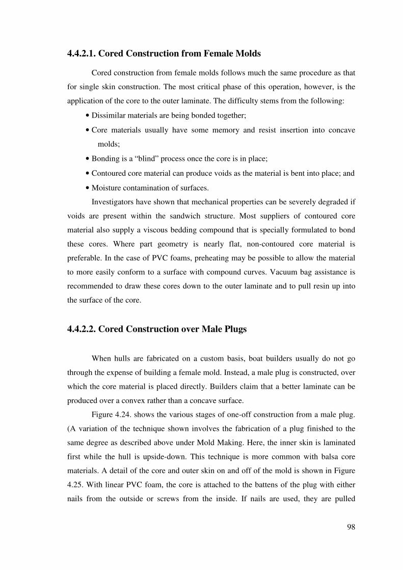
98
4.4.2.1. Cored Construction from Female Molds
Cored construction from female molds follows much the same procedure as that
for single skin construction. The most critical phase of this operation, however, is the
application of the core to the outer laminate. The difficulty stems from the following:
• Dissimilar materials are being bonded together;
• Core materials usually have some memory and resist insertion into concave
molds;
• Bonding is a “blind” process once the core is in place;
• Contoured core material can produce voids as the material is bent into place; and
• Moisture contamination of surfaces.
Investigators have shown that mechanical properties can be severely degraded if
voids are present within the sandwich structure. Most suppliers of contoured core
material also supply a viscous bedding compound that is specially formulated to bond
these cores. Where part geometry is nearly flat, non-contoured core material is
preferable. In the case of PVC foams, preheating may be possible to allow the material
to more easily conform to a surface with compound curves. Vacuum bag assistance is
recommended to draw these cores down to the outer laminate and to pull resin up into
the surface of the core.
4.4.2.2. Cored Construction over Male Plugs
When hulls are fabricated on a custom basis, boat builders usually do not go
through the expense of building a female mold. Instead, a male plug is constructed, over
which the core material is placed directly. Builders claim that a better laminate can be
produced over a convex rather than a concave surface.
Figure 4.24. shows the various stages of one-off construction from a male plug.
(A variation of the technique shown involves the fabrication of a plug finished to the
same degree as described above under Mold Making. Here, the inner skin is laminated
first while the hull is upside-down. This technique is more common with balsa core
materials. A detail of the core and outer skin on and off of the mold is shown in Figure
4.25. With linear PVC foam, the core is attached to the battens of the plug with either
nails from the outside or screws from the inside. If nails are used, they are pulled

99
through the foam after the outside laminate has cured. Screws can be reversed out from
inside the mold.
Figure 4.24. Simple, Wood Frame Male Plug used in Sandwich Construction (Greene 2004)

100
Figure 4.25. Detail of Sandwich Construction over Male Plug (Greene 2004)
4.5. Evolution of Recreational Boat Construction Techniques
From the 1950s to the 2000s, advances in materials and fabrication techniques
used in the pleasure craft industry have helped to reduce production costs and improve
product quality. Although every boat builder employs unique production procedures
that they feel are proprietary, general industry trends can be traced over time, as
illustrated in Figure 4.26.
Pounds of Reinforcement (millions)
500
400
300
200
100
0
1960 1963 1966 1969 1972 1975 1978 1981 1984 1987 1990 1993 1996
Year
Figure 4.26. Annual Shipment of Reinforced Thermoset and Thermoplastic Resin Composites for the Marine Industry with Associated Construction Developments. (Greene 2004)
Sequence Shows Finished Laminate and Removal from
The Male Plug

101
4.6. Recreational Boat Construction Techniques
There are various fabrication processes applicable to marine composite
structures such as hand lay up, spray up, compression molding, filament winding,
pultrusion, vacuum bag molding, autoclave molding and resin transfer molding. The
most common technique used for large structures such as boat hulls, is the open mold
process. Specifically, hand lay-up or spray-up techniques are used. Spray-up of chopped
fibers is generally limited to smaller hulls and parts.
%0 %10 %20 %30 %40 %50 %60 %70 %80 %90 %100
Hand Lay-Up Construction . Vacuum Assist . Autoclave Cure . Spray-Up . Resin Transfer Molding .
Figure 4.27. Building Processes (Greene 2004)
4.6.1. Open molding
Open molding is the most common method in marine production process used to
fabricate composites parts accounting for over 40% of composites processed world-
wide. It is a relatively simple process with low investment cost but a high degree of
manual handling. Virtually all types of reinforcement can been used in open molding
which together with the use of core materials to create sandwich structures enables
access to the widest range of mechanical and structural performance of any composites
process. Unsaturated polyester resins dominate in this area but epoxy and vinyl ester
resins are also common. Open molding can be used for a very wide range of moldings
from caravan parts and cladding panels to boat hulls and radomes. Typical economic
run lengths range from 2 or 3 individual parts up to several hundred.

102
4.6.1.1. Hand Lamination
The process starts with the construction of a mould. The mould is most
commonly constructed from composites material using a model made from wood,
plaster or any other suitable modeling material. Only one, normally female, mould half
is needed which defines the exterior surface of the part. Most often the first stage of
molding is to brush or spray a polymer coating or gel coat onto the mould surface. Gel
coats are available in a wide range of different colors and effects and are selected to
protect the part from environmental degradation or chemical attack and provide the
desired aesthetics.
After the gel coat has been allowed to cure fiber reinforcement in sheet form is
laid in place in the mould. Glass fiber is the most common reinforcement in the form of
chopped strand mat but other fibers such as carbon or aramid may be used. A very wide
range of reinforcement types are available and can be positioned and oriented in the
mould giving the ability to vary the mechanical performance across the part. The design
of the glass fiber pack is a key to the performance of the composite part and the ability
to change it at will gives great flexibility to the hand lay process.
The next stage of the process is to pour liquid catalyzed resin over the
reinforcement and to work it into the reinforcement using rollers. This process is very
labour intensive but extremely important as it ensures even distribution of the resin, full
impregnation and wetting out of the reinforcement and removal of air. Unless the
process is carried out effectively the composite part will not perform correctly. Further
layers of reinforcement and resin are applied according to the requirements of the part
and core materials such as rigid foam, balsa wood or honeycomb may be included to
create sandwich structures.
When the lay up is complete the molding is left to cure. This normally occurs at
ambient temperature and can take anything up to 10 hours. The molding is then released
from the mould and trimmed to remove excess material from the edges of the molding.
Sometimes moldings are cured at slightly elevated temperatures to improve speed and
productivity and may also be post cured at even higher temperatures to achieve the
maximum performance.

103
4.6.1.2. Spray Lamination
Spray lamination is very similar to hand lay-up apart from the method of placing
the reinforcement and the resin into the mould. Rather than using reinforcement in the
form of mat, resin and reinforcement are co-sprayed into the mould using a combined
resin spray and chopper gun.
Figure 4.28. Spray Lamination. WEB_9 (2004)
This process is much easier and faster than hand lay-up and can be automated
using robotized spray guns. This does eliminate much of the manual labor involved in
positioning the reinforcement in the mould and will result in higher productivity
although rolling is still necessary to ensure proper consolidation of the part. Spray
lamination can be used in combination with hand lay where different types of fiber or
constructions are required to achieve specific properties.
4.6.2. Closed molding
Closed molding is the name given to fabrication techniques in which reinforced
plastic parts are produced between the halves of a two-part mold or between a mold and
a flexible membrane, such as a bag. There are four types of closed molding methods
that are being used in boat manufacturing operations: vacuum bagging, vacuum-assisted
resin transfer molding, resin transfer molding, and compression molding with sheet
molding compound.
Air Pressurized Resin Chopper Gun
Fibre
Optional Gel Coat
Resin Catalyst Pot

104
4.6.2.1. Vacuum Bagging
An increasing number of builders are using vacuum bag techniques to produce
custom and production parts. By applying a vacuum over a laminate, consolidation of
reinforcement materials can be accomplished on a consistent basis. A vacuum pressure
of 14.7 psi is over a ton per square-foot, which is much more pressure than can
reasonably be applied with weights. (Marshall 1993, Greene 2004). As with most
advanced construction boat building practices, specialized training is required and
techniques specific to the marine industry have evolved.
Vacuum bagging is a partially closed molding technology. It uses techniques
similar to open molding but with a modification in the resin curing stage. After resin has
been applied (either by hand lay-up or spray lay-up), a flexible, clear plastic sheet is
placed over the wet laminate and sealed along the edge of the mold to form a "bag." A
porous material called a bleeder sheet is also placed under the bag and a hose connected
to a vacuum pump is sealed under the edge of the bag. The vacuum pump is used to
draw the air out from under the bag and press the bag down onto the part. The pressure
of the vacuum removes any trapped air and excess resin from the part and presses the
layers of laminated material together. This technique is used to increase the fiber-to-
resin ratio, which generally increases the strength of a part, and also to obtain a good
bond between FRP skins and non-FRP core materials, such as wood or foam. Core
materials are often sandwiched between layers of FRP to make a thicker and stiffer part
without significantly increasing the part's weight.
The most common use of vacuum bagging in marine construction is for bonding
cores to cured laminates. This is called “dry-bagging,” as the final material is not wet-
out with resin. When laminates are done under vacuum, it is called “wet-bagging,” as
the vacuum lines will draw directly against reinforcements that have been wet-out with
resin. For wet-bagging, a peel-ply and some means for trapping excess resin before it
reaches the vacuum pump is required. (Lazarus 1994)
Table 4.1. and Figure 4.29. list some materials used in the vacuum bag process.
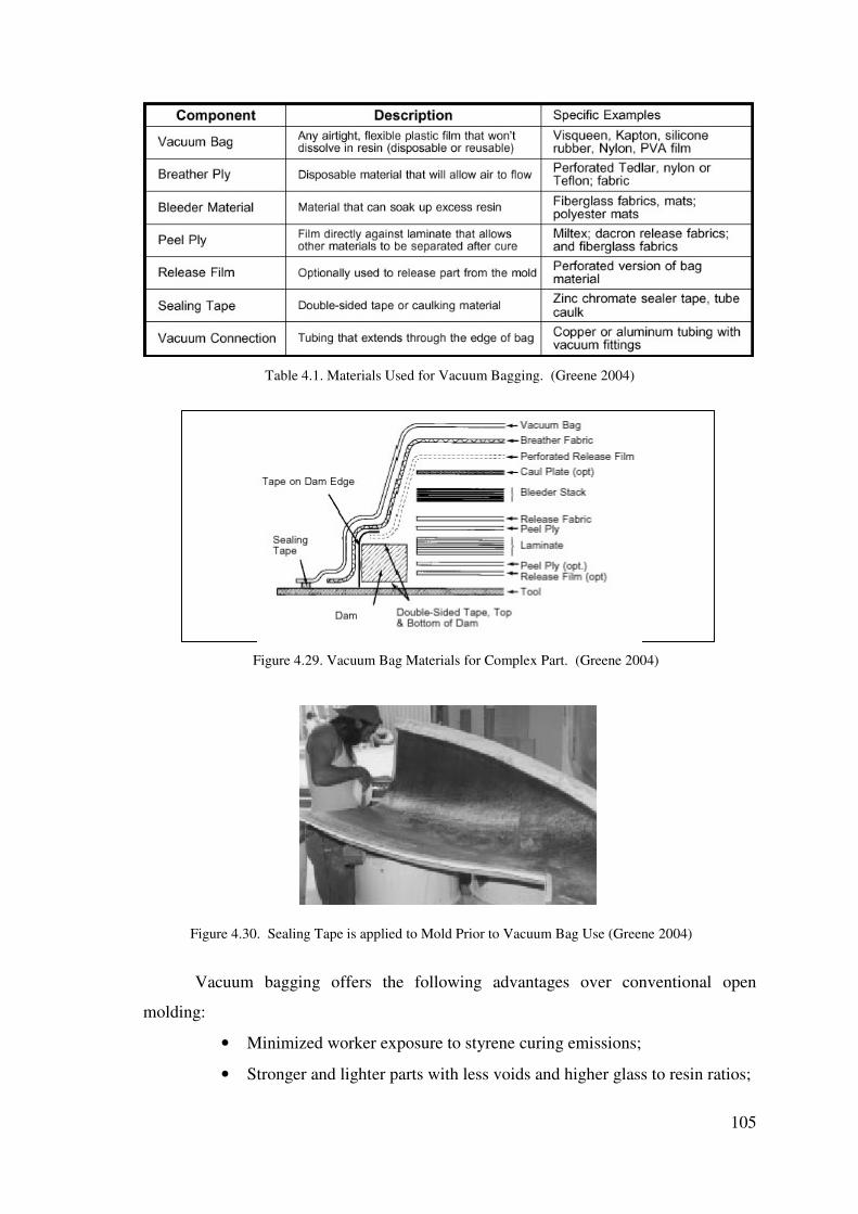
105
Table 4.1. Materials Used for Vacuum Bagging. (Greene 2004)
Figure 4.29. Vacuum Bag Materials for Complex Part. (Greene 2004)
Figure 4.30. Sealing Tape is applied to Mold Prior to Vacuum Bag Use (Greene 2004)
Vacuum bagging offers the following advantages over conventional open
molding:
• Minimized worker exposure to styrene curing emissions;
• Stronger and lighter parts with less voids and higher glass to resin ratios;

106
• Better bonding between FRP skins and non-FRP core materials; and
• Reduced labor and rolling equipment needs because rolling to remove air
bubbles and excess resin is not needed.
Figure 4.31. Overhead High- and Low-Pressure Vacuum Lines. (Greene 2004)
4.6.2.2. Vacuum-Assisted Resin Transfer Molding
Vacuum-Assisted Resin Transfer Molding (VARTM) is a closed molding
technology that uses a vacuum to pull resin into dry fiberglass reinforcements that are
placed into a closed mold. The closed mold may be formed using a flexible plastic sheet
or "bag" as in vacuum bagging, or by a rigid or semi-rigid cover that matches the shape
of the mold. In all variations, the bag or cover is sealed to the mold and vacuum
pressure is used to draw resin from an outside reservoir into the sealed mold through a
system of distribution tubes and channels placed under the bag or cover.
One VARTM process that has been used by several boat manufacturers is a
patented technology called the Seeman Composites Resin Infusion Molding Process
(SCRIMP) which is licensed by SCRIMP Systems, LLC.

107
Figure 4.32. Dry Reinforcement In-Place for SCRIMP Process (Greene 2004)
Figure 4.33. SCRIMP Infusion Arrangement (Greene 2004)
In the SCRIMP process, the mold is coated with a gel coat finish and a skin coat
is applied using conventional techniques. Dry reinforcements and core materials are
then placed in the mold. The resin distribution system and the bag are then placed over
the mold and sealed to the edge of the mold. The vacuum is then applied to pull the bag
against the mold and the reinforcements and the bag is checked for leaks. Valves to the
resin supply system are then opened and the resin is pulled into the reinforcements by
the vacuum. When the reinforcements are thoroughly saturated with resin, the resin
supply is shut off and the part is allowed to cure under a vacuum. After curing, the bag
is removed and is either discarded or reused, depending on the material from which it is
made. Disposable bags are made from plastic film, whereas reusable bags are made
from silicone rubber. A silicone bag can be used for more than 500 parts.

108
Figure 4.34. SCRIMP U.S. Coast Guard Motor Lifeboat Built by OTECH. (Greene 2004)
The SCRIMP process has been used by one manufacturer (TPI Composites,
Inc.) to build small (13 foot) sailboats and large sailboats up to 90 feet. TPI builds about
400 boats per year using SCRIMP and also uses the process to manufacture other
reinforced plastic parts, including windmill blades and exercise pools. Several other
smaller boat manufacturers that are not major HAP sources are also using the process to
build both power and sail boats of a variety of sizes including motor surf lifeboats for
the U.S. Coast Guard.
Figure 4.35. Schematic of SCRIMP Process. (Greene 2004)

109
The VARTM process has the following advantages over conventional open
molding:
• Minimizes worker exposure to resin and styrene; this makes for a cleaner
and more comfortable work environment and reduces the need for
personal protective equipment such as respirators, gloves, and coveralls;
• Reduces the need for ventilation make-up air (and associated electrical
and heating costs) to maintain styrene concentrations within acceptable
exposure levels;
• Reduces the labor needed to apply resin and perform detail rolling of the
laminate;
• Reduces the need for clean-up solvents for resin application equipment;
• Reduces the need for resin application equipment (e.g., spray guns,
pumps, and detail rollers) and associated maintenance costs;
• Produces parts with a higher glass-to-resin ratio and fewer voids, which
generally results in stronger and more durable parts;
• Can produce lighter parts if a core material is incorporated into the
laminate in place of some of the fiberglass; and
• Produces more consistent parts because the fiberglass reinforcements are
placed into the mold dry and can be precisely located before resin is
applied and because resin application is more controlled and predictable.
4.6.2.3. Resin Transfer Molding
Resin transfer molding (RTM) uses two rigid mold halves to provide the shape
for fabrication of FRP boat parts. In a typical resin transfer molding (RTM) operation,
gel coat is spray applied to the inside surface of both halves of the mold so that the part
has two finished sides, instead of one as in open molding. After the gel coat cures, the
dry reinforcement is laid inside the mold and the mold is closed with clamps. When
closed, the two halves of the mold mate together with a narrow space between them
equal to the thickness of the finished part. Catalyzed resin is injected into the closed
mold where it saturates the fiberglass. While the part is still in the mold, the resin cures.
After the resin has cured, the mold is opened and the finished part is removed.

110
Figure 4.36. Resin transfer molding. (Greene 2004)
The RTM process is most economical for making many copies of small parts,
especially when a smooth finish is desired on both sides of the part. Typical applications
of RTM in boat manufacturing are for making hatch covers, doors, and seats.
The RTM process has several advantages compared to conventional open
molding :
• RTM is more economical than open molding for producing many copies
of relatively small parts such as hatch covers and seats because of
reduced labor during resin application; the use of pre-formed fiberglass
reinforcements can add to these labor savings;
• Minimizes worker exposure to resin and styrene; this makes for a cleaner
and more comfortable work environment and reduces the need for
personal protective equipment such as respirators, gloves, and coveralls;
• Reduces the need for clean-up solvents for resin application equipment;
• RTM produces more consistent parts than open molding; C RTM can
produce parts with two smooth finished sides; and
• Parts can be produced more quickly with RTM because the heat of
injecting the resin accelerates the resin curing and allows for faster mold
cycle times.
Laid up Mat or Woven Reinforcement
Seal/Vent
Resin Injection Port

111
4.6.2.4. Compression Molding using Sheet Molding Compound
Compression molding involves the use of a prepared compound such as sheet
molding compound (SMC) and a large hydraulic press to produce FRP parts. The
prepared SMC sheet is composed of resin and fiberglass fibers. To create a FRP part
with compression molding, SMC sheets are cut to the proper size and put into a
matched male and female mold. The two molds are pressed together in the hydraulic
press under several tons of pressure. The SMC is forced into all areas of the mold and
cures in the closed mold under high heat and pressure in a matter of minutes. Several
facilities are currently using compression molding with SMC to produce hulls, decks,
and other parts for PWC. These facilities are producing parts on the order of tens of
thousands per year.
Figure 4.37. Compression molding. (Greene 2004)
The compression molding process with SMC has the following advantages
compared to other molding technologies:
• The rapid curing of the parts under high heat and pressure permits rapid
mold cycle times and high production volumes;
• The automated process and the use of SMC reduces labor costs
compared to open molding; and
• Minimizes worker exposure to resin and styrene; this makes for a cleaner
and more comfortable work environment and reduces the need for
personal protective equipment such as respirators, gloves, and coveralls;
Female mold half
Male mold half Heat and pressure
Molding compound

112
• Reduces the need for clean-up solvents for resin application equipment;
and
• There is no need to apply gel coat to the mold prior to molding.
4.7. Future Trends for FRP Boat Construction
Prepregs: The term prepreg is short for pre-impregnated material and refers to
reinforcements that already contains resin and are ready to be placed in a mold. The
resin (usually epoxy) is partially cured to a “B-stage,” which gives it a tacky
consistency. Prepreg material must be stored in freezers prior to use and require
elevated temperatures for curing. Aerospace grade prepregs also require elevated
pressures achieved with an autoclave for consolidation during curing.
A lot of builder use prepregs for the construction of lightweight, fast vessels.
Notable applications include America's Cup sailboats and hydroplanes racing on the
professional circuit. Because marine structures are quite large, curing is typically
limited to oven-assisted only, without the use autoclaves. Some marine hardware and
masts are made using conventional aerospace techniques.
Figure 4.38. Prepreg Material is positioned Figure 4.39. Prepreg Material is consolidated
in Mold (Greene 2004) solidated in Mold (Greene 2004)

113
Prepregs are classed by the temperature at which they cure. High performance,
aerospace prepregs cure at 350°F or higher and commercial prepregs cure at 250°F.
A new class of “low energy cure” prepregs is emerging, with cure temperatures
in the 140°F to 220°F range. These materials are particularly suited to marine
construction, as curing ovens are typically temporary structures. (Juska et al. 1996) Eric
Goetz used this method to build all of the 1995 America's Cup defenders.
Figure 4.40. Deck Beam Figure 4.41. Hydroplane Hull and Cockpit Assemblies at Ron Construction Jones Marine (Greene 2004)
(Greene 2004)
Builders such as Goetz and Ron Jones who have developed techniques for
fabricating marine structures with prepregs are hesitant to go back to wet lay-up
methods. They cite no styrene emission, ease of handling, increased working times and
higher part quality and consistency as distinct advantages. On the down side, prepreg
material costs about four times as much as standard resin and reinforcement products;
requires freezer storage; and must be cured in an oven. As reduced VOC requirements
force builders to look for alternative construction methods, it is expected that demand
will drive more prepreg manufacturers towards the development of products specifically
for the marine industry.
Figure 4.42. Cure Oven Used for Masts and Hardware at Goetz Marine Technology (Greene 2004)

114
Thick Section Prepregs: Composite Ships, Inc. of Arlington, VA is developing
a prepreg process based on DSM, Italia materials that may lead to the construction of
large, thick marine structures. With promising compressive strengths near 70 ksi,
material costs over $5/lb are expected to be offset by the need for fewer plies and ease
of fabrication.
Figure 4.43. Prepreg Ply of E-Glass is Rolled Out on Consolidation Table (Greene 2004)
Figure 4.43. shows unidirectional prepreg being laid out on a preparation table.
Successive plies of 0° or ±45° E-glass/epoxy are consolidated in bundles of six, with a
one inch offset to create a lap joint edge. The bundled group of plies is then passed
through a consolidating “wringer,” as shown in Figure 4.44. (Greene 2004)
Figure 4.44. Prepreg “Bundle” of Six Layers of Unidirectional E-Glass is Passed Through Consoli-dator
for a Stiffener by Composite Ships (Greene 2004)
The “tacky” bundle is then placed in a metal mold and “smoothed” in place.
Hand consolidation with plastic putty knives to remove trapped air is assisted by the
addition of some base resin, which is a B-stage epoxy.
115
For components such as stiffeners, the prepreg can be semi-cured at 120°F on a
wood mold to create a stiff form to work with. The component is then bonded to the
hull with a resin putty.
The prepreg is stored at 0°F and warmed to room temperature for one hour
before use. After stabilization in the mold, the material can stay at a stabilized state for
several months before the structure is cured. An entire hull structure, including semi-
cured internals, is then cured in an oven built using house insulation materials. Heat is
also applied to the steel mold via thermocouple feedback control. Full cure requires a
temperature of 185°F for 24 hours. The U.S. Navy has sponsored the production of a
half-scale Corvette midship hull section to validate the process for large ship structures.
Thermoplastic-Thermoset Hybrid Process: A company called Advance USA
is currently constructing a 15 foot racing sailboat called the JY-15 using a combination
of vacuum forming, injection foam and resin transfer molding. Designed by Johnstone
Yachts, Inc. the boat is a very high-performance planing boat.
The hull is essentially a three-element composite, consisting of a laminated
thermoplastic sheet on the outside, a polyurethane foam core and an inner skin of RTM
produced, reinforced polyester. The 0.156 inch outer sheet is vacuum formed and
consists of pigmented Rovel ® (a weatherable rubber-styrene copolymer made by Dow
Chemical and used for hot tubs, among other things) covered with a scratch resistant
acrylic film and backed by an impact grade of Dow's Magnum ABS. The foam core is a
two part urethane that finishes out to be about three pounds per cubic foot. The inner
skin is either glass cloth or mat combined with polyester resin using an RTM process.
The hull and deck are built separately and bonded together with epoxy as shown in
Figure 4.45. Although investment in the aluminum-filled, epoxy molds is significant,
the builder claims that a lighter and stronger boat can be built by this process in two-
thirds the time required for spray-up construction. Additionally, the hull has the
advantage of a thermoplastic exterior that is proven to be more impact resistant than
FRP. Closed-mold processes also produce less volatile emissions. (Miller 1989)

116
Figure 4.45. Schematic of JY-15 Showing Hull and Deck Parts prior to Joining with Epoxy (Greene 2004)
Preform Structurals: Compsys of Melbourne, FL has developed a system for
prefabricating stringer systems of various geometries for production craft that contain
all dry reinforcement and core material. Prisma preform systems feature a dry fiber-
reinforced outer surface that is cast to shape with a two-part, self-rising urethane foam
core. Sufficient reinforcement extends beyond the stringers to permit efficient tabbing
to the primary hull structure.
Preform stringer and bulkhead anchor systems are delivered to boat builders,
where they are set in place and coated with resin simultaneously with the primary hull
structure. Compsys claims that builders realize significant labor savings and improved
part strength and consistency.
Figure 4.46. Two-Part Expansion Foam is Injected into Stringer Molds at Compsys with Careful
Monitoring of Material Flow rate and Duration (Greene 2004)
UV-Cured Resin: Ultra violet (UV) cured resin technology, developed by
BASF AG, has been available in Europe for the past 10 years, and is being promoted in
the U.S. by the Sunrez tm Corporation of El Cajun, CA. The technology promises long
pot life and rapid curing of polyester and vinyl ester laminates.

117
BASF developed a light initiator for rapid curing of polyester and vinyl ester
resins at their laboratories in West Germany ten year ago. Total cure times of 3 minutes
are typical for parts of 3/16" and under 10 minutes for parts 1/2" thick, using open
molds and hand or machine application of the resin and glass. Sunrez tm also claims
that styrene emissions can be reduced by up to 95% depending on the fabrication
method used. (This is based on a fabrication process patented by Sunrez tm ).
Figure 4.47. One-Half Scale Corvette Hull Test Section Built for the U.S. Navy Using the Sunrez Process
(Greene 2004)
A BASF photo-initiator is added to a specially formulated version of a
fabricator's resin and is shipped in drums or tanker to the shop. The resin is drawn off
and used without the addition of a catalyst. The part is laminated normally and any
excess resin is saved for the next part.
When the laminator feels that he has completed the laminate, the part is exposed
to UV light, and cured in 3 to 5 minutes. (Greene 2004)
CNC (Computer Numerical Control) Design Automation: “Today’s robotics give
boat builders a range of tooling options nor available just ten years ago.” (Harp 2001)
Recent innovations in hardware and software have opened new horizons in the way
technology used in boat building industry. One of them is CNC milling in boat
production. The goal in CNC milling is to be able to cut the plug automatically without
any lengthy final preparation by hand. A variety of materials can be machined by CNC,
including foam, wood, plastic and fiberglass compounds.
Machined tooling for FRP boats can take variety of forms such as From CNC-
cut frames for manually constructed plugs, to limited production female tools, to CNS-
cut plugs over which production female molds are laminated.

118
• CNC Milling
A milling machine is a machine tool that removes material from a work piece by
rotating a cutter and moving it into the material. CNC design automation consists of five
stages. These are concept stage, design stage, model stage, milling stage and molding
stage.
Firstly a concept study project is prepared and then 3D model is made for CNC
from this concept study. (Figure 4.48.) After 3D model, milling stage can start. (Figure
4.50. – Figure 4.41.). By the finish of milling process, molding process start in which
the final mold is produced. (Figure 4.52. - figure 4.53.)
���������� Figure 4.48. 3D model of a boat Figure 4.49. Finish Project of race boat
WEB_19 (2004) WEB_19 (2004)
Figure 4.50. CNC milling for hull Figure 4.51. Cockpit. WEB_19 (2004)
WEB_19 (2004)

119
Figure 4.52. Molding process. Figure 4.53.Final mold. WEB_19 (2004)
WEB_19 (2004)
• Summary of CNC Milling Process
1. Design the boat using some form of CAD hull or surface design program.
2. Write a transfer geometry file (DXF, IGES, etc.) of the hull
3. Read the geometry file into the CAM program
4. Adapt or correct the geometry to meet the needs of the CAM software
5. Define the cutter tool paths over the surfaces using the CAM software
6. Break the job into pieces that will fit on the machine
7. Mill the individual pieces
8. Drill the connection pin locations or alignment marks for the milled parts
9. Prepare the plug for use or use it to create the final mold
4.8. Investigation on production of Gulets
There is a lot of gulet definition related to length, hull form and rigs of gulet.
The authoritative definition of gulet is: " A two-masted, lightly rigged sailing vessel,
smaller than a brig, with a fully rigged foremast with square sails and the mainmast with
gaff-rigged mainsail." WEB_5 (2004)

120
However, contemporary usage amongst the Turkish sailing community differs.
A gulet is a two-masted, ketch or schooner-rigged steel or wooden yacht with widely
varying sail plans and characterized by a wide, rounded stern.
Figure 4.54. View of a Gulet. WEB_5 (2004)
A boat has to be constructed strong enough against to environmental loads,
suitable to international rules and has to be comfortable. When these required conditions
are provided, boats are going to be preferred in local and international areas whatever its
material and production method.
Figure 4.55. View of a Gulet’s stern. (Gölpınar 2004)
4.8.1. Production Materials and Methods of Gulet
There are two-type material used in production of gulet such as wood and steel.
Steel gulets’ market is restricted because of the people’s demand, which towards to
natural yacht with wood. There is only a firm that produce steel gulet called Ege-Yat.

121
They prefer this material because of its low cost, low material waste and the low
production time when compared to wooden gulets. But the consumer’s demand is still
toward to wooden gulets because of its comfort, natural aesthetic and natural thermal
insulation. With the development in modern glues and application methods, usage of
wood gains importance again for production of boats.
Conventional wooden boats must be built with suitable process trees. However,
modern glues (epoxy resins) have been useable for boat manufacturers. Wooden boat
technology has two new methods.
Monocoque wooden boat building method: This technology is being used
especially in Europe, USA and Australia. Wooden boats are built by lamination method
completely.
Hybrid wooden boat building method: This technology is being preferred
because of investment cost is less than investment cost of monocoque wooden boat and
structural strength is higher than structural strength of conventional wooden boat. In this
method, boat’s parts that are keel, stem and frame are built by lamination method.
In hybrid wooden boat building method is used both conventional and
laminated wooden boat building methods.
4.8.1.1. Conventional Wooden Boat Building Method
This method is cheaper than the laminated wooden boat building method. But, it
has low strength against to dynamic and static loads. Gaps on board are caulked. After
this application, it occurs a lot of problems on boat, especially on underwater surfaces.
In this method, wood parts are fixed with nails and nuts. Because of temperature and
moisture ratio variation, fixed parts leave from each other in the future. So, repairing of
these boats is both harder and more expensive than repairing of laminated wooden
boats. Repairing works of these boats are cleaning and removing paint on board. Then,
the boat is repainted. However, it must be recaulked about one times at 5 years. All
these repairing works can be done about 3 months after they were carried marina.

122
Figure 4.56. View of a maintaining Gulet. (Gölpınar 2004)
Generally, naval architect isn’t worked in yards where is built conventional
wooden boat. Boat builders don’t think about using new technologies and engineering
services. They are contented with old methods in this building. So, it is used excessive
wooden material for building that the boats become heavy. This occurs to selected
stronger engine. Thus, maintenance costs also increase. It is necessary to select correct
wooden material for hull form in this method. So, it takes a lot of times. After
collection, all collected materials are spread and then the most suitable are selected by
model. It’s necessary to have a wide area and long working time to operate. Hierarchy
of wooden boat building was listed below:
1. Ballast is seated on launching way after ballast was prepared by sheet iron.
The ballast decreases the center of gravity of boat and supports wooden keel.
Because of decreasing the center of gravity becomes stable the boat.
2. Keel is seated on the ballast after it was prepared. The keel can be prepared
from adding wooden each other. Stem post and stern are prepared and seated on
the keel. It is prepared keelson for seating floors on the keel.
3. Preparing floors. If it couldn’t be found suitable tree form for a floor, it is
prepared as an adding frame. Then, two similar frames (sister frames) are seated
side by side on keelson for obtaining enough structural strength by floors. While
the frames are being preparing, woods are diminished about 50%.
4. After the inside keel is prepared; it is seated on the keelson and fixed on the
keel by galvanized nuts.

123
5. Stringers are fixed frames after they were prepared. Stem is strengthened
against to effects that will come from sea. Beams, carlins and puntels were
prepared. Board is covered by carved planks and fixed on frames by nails.
6. Deck is covered and cabins are built. Tanks and engine beds are prepared.
7. Equipment is seated. After board was cover, it is caulked. Then, it is puttied
and painted.
Figure 4.57. Wooden Framework of a Gulet. (Gölpınar 2004)
4.8.1.2. Laminated Wooden Boat Building Method
Although wood is a suitable material for boat building, it can decay and burn
easily. Today, these problems of wood can be solved by wood lamination method. It’s a
process that glue (epoxy resin) is injected into the wood to protect harmful organisms
(fungus, insects, etc.). Epoxy resins also are used to protect the wood against the
moisture in this method. All surfaces covered by epoxy resin don’t let to penetration of
moisture into the wood. So, strength of wood doesn’t change. Properties and advantages
of epoxy resins were listed below:
1. They are fluent materials. So, they penetrate into the wood easily.
2. Their shrinkage coefficient is low. So, tension does not occur between epoxy
resins and the other filling materials.
3. They protect wood surfaces against to environmental effects and chemical
materials.

124
4. It’s easy to use epoxy resins with other filling materials. After using them, it
does not occur any cracking and removing on the surface.
5. They increase the wooden life. However, wood diminution is about 10% in
laminated wooden boat building method. So, wood consumption decreases.
6. Laminated wood materials have more advantage than the other boat building
materials.
7. When moisture ratio in wood cells increases, strength of wood decreases. For
example, strength of a wood having 17% moisture ratio is 6% higher than the
strength of wood having 30% moisture ratio. So, in wooden boats, especially on
board and underwater surface, have to be used epoxy resins for protecting.
Figure 4.58. Laminating views of a keel. (Gölpınar 2004)
There are some important points to use epoxy resins. Before using epoxy resin,
it should be taken information from epoxy resins manufacturers and experts and cost
analysing should be performed. Temperature-moisture limits, equipment and surface
tolerances are very important in this method. They have to be used carefully to prevent
surface faults.
Figure 4.59. Laminated ballast and keels. (Gölpınar 2004)

125
The wood used in lamination method must be without natural resin and knot.
Mahogany and iroko are very suitable woods for using lamination method. If wood has
a natural resin, epoxy resin can not penetrate into the wood easily. If epoxy resin cannot
penetrate wood, moisture penetrates in to the wood in the future.
Figure 4.60. Laminating views of hull of a Gulet. (Gölpınar 2004)
In lamination method, the wood which has 6-14% moisture ratio is cut layer by
layer. Then, these layers are stricken with epoxy resins. This method is used to make
keel and also to cover the board. When all parts of boat are built by this method, boat
has high strength against dynamic and static loads.
If wooden board was built by lamination method, it does not occur decay.
However, repairing of laminated wooden boat is easy and cheap. Repairing works are
cleaning and repainting on board. So, it is enough 5 days for repairing. Because of a
laminated wooden boat is lighter than conventional wooden boat, fuel and lubrication
oil consumption is less. This factor occurs decreased of maintenance cost at laminated
wooden boat. (Gougeon 1990, Kahraman 2000)
4.8.1.3. FRP Boat Building Method
There is a lot of method for FRP production of gulet such as conventional
methods (hand lamination and spray lamination) and industrialized techniques (vacuum

126
bag, resin transfer and SMC etc). But it is realized that while making an investment on
feasibility of FRP gullets in Bodrum, the gulet manufacturers don’t want to construct
FRP gulet, although FRP has advantages over the other boat building materials.
FRP needs initial investment, experience and knowledge, especially for more
industrialized methods. Because of this reason, the manufacturers don’t want to change
their construction methods. In addition to this, they think that FRP gulet will not be a
attractive product for boat market because of the consumer’s demands, which include
aesthetic look and traditional warmness of wooden gulets.
Because of these reasons, there is not an example of FRP gulet. It can become
realty if a manufacturer spend time for details of molding and make investment for
equipments and information of production techniques by starting from small length of
gulets.

127
CHAPTER 5
CONCLUSION
This study has attempted to find out the suitable material for serial production of
recreational boats and to explain the manufacturing methods, which belong to this
material. Tables and practical experiences knowledge, which include materials’
mechanical characteristics, durability, corrosion resistance, maintenance necessity,
impact resistance etc., are used for the material comparison of boats. The comparison
showed that although FRP (Fiber Reinforced Plastic) has disadvantages such as high
material cost, tendency to creep, less abrasion resistance according to metals, less
stiffness, structural vibrations; it also has the advantages of low maintenance cost,
lightweight, resistance to the marine environment, high strength, ability to mold
complex shapes, easy repair, seamless construction and high heat resistance. These
properties proved that its advantages greatly overshadow the disadvantages .In addition
to these advantages, FRP gives the opportunity of limited production because of it’s
construction method which need a mold. By using the same molds, a lot of boat can be
produced. Thus manufacturer gains time and the production and labor cost goes down.
GRP (Glass Reinforced Plastic) is the most common used type of FRP in boat
construction industry because of its low cost. With the development of material
technology, advanced FRP materials such as carbon fiber, aramid and hybrid fiber start
to be used in boat construction. Although these new materials have some advantages
according to GRP, because of their high price they are just used in restricted area such
as race boats and special design crafts. For the future researches, researchers can
investigate the usage area of these advanced composites for industrial products, a
solution for the high price of the material and the usage properties for different product.
Although material and manufacture method has a big portion for being a
solution for increasing market demand, the design process (where material and
manufacturing methods are decided) has also another big portion on the sale of the
product because of giving attractiveness to it. Even if the product has a high quality
material, a product without a good design can also be unsuccessful on the market.
Unlike the commercial ships, aesthetic is very important for recreational boats. It also
plays an important role to sell the vessel. Therefore the design chapter, where the

128
material choice and manufacture method is determined, is presented after introduction.
In this chapter, boat design characteristics, the owner’s design requirements, design
process and design methods are discussed.
The exterior design, interior design, boat material and manufacture methods are
parts of a whole which have to be solved with a multidisciplinary design work
comprised of craftsmen, designer and engineer. The designers role is not only to draw
the project with lines or working in cooperation with engineers for forming the
mechanical properties, but also to deal with the boat design as a whole with material
and manufacture method alternatives, to give an aesthetic look to boat, to give different
interior design possibilities and to form exterior elevation alternatives which are suitable
for owner’s demands and needs. In Europe and USA, there are a lot of boat or yacht
design schools, which play an important role on finished design’s success in boat
market. Because of this reason, boat/yacht design departments in universities should be
activated in Turkey where the practical and theoretical knowledge comes from
country’s craftsmen’s and engineers’ past experiences and our geographical location,
which already have been for the fields of manufacturing and engineering. If this
knowledge and design is gathered with today’s technological developments in material
and production methods, our own brand can be created and by the help of this our
country can get an important role in the boat market.
There are different FRP boat production methods, both conventional methods
such as hand lamination and spray lamination and more industrialized methods such as
SMC, vacuum bagging, and resin transfer molding. These applications all have different
advantages and disadvantages when compared with each other such as time benefit,
cost benefit, clean finish, and ability to mold complex shapes etc., These titles have
presented as construction techniques at the former chapter of conclusion. It is found that
the hand lamination and spray lamination methods (which are simple, cheap and needs
less investment) are more common in use than the advanced fabricating techniques like
SMC, resin transfer molding, vacuum bag (which are expensive methods needs
technical knowledge but causes gain in time and labor). The proposal for an investor
(while deciding the boat manufacture method) is to take care of the cost estimates for
the investment, technical knowledge, and the enough space for the right equipments.
The increase of the importance of the computer usage at the stages such as
design process and manufacture process for the boat market became attractive to me
during the preparation of this thesis. It is mentioned that parallel to the developments at

129
the technology; computer is very important at every stage of the design and manufacture
processes such as for drawings, for evaluation of technical analysis of the boat and to
form the molds at the CNC tables with computer based 3 dimensional drawings. This
technology needs a fore payment but it tolerates itself by the gain at time, labor, creating
complex forms. For future researchers “the computer program’s for the boat design and
the computer based CNC technology’s” which affects the design and product can be a
title for thesis.

130
REFERENCES
Book : Aksu, �. and Tuzcu, C., 1995. “Resent Developments in Small Craft Design: An
Overview” in Yachting Technology’ 95, edited by N. Teko�ul and G. Ne�er, (Piri Reis, �zmir), pp. 65-81.
Atkin, W., 1997. Of Yacht And Men, ( Tiller, Md, USA), pp. 6-9. Brewer, T., 1994. Understanding Boat Design, (International Marine Camden, Maine),
pp.80-102. Colvin, E., T., 1992. Steel Boat Building, (International Marine Camden, Maine),
pp.13-17. EPRI, 2000. Composites (Epri Center, Dublin), pp.4-7. Fyson, J., 1985. Design Of Small Fishing Vessels, (FAO, Italy), pp.80-20, pp. 312-320. Gerr, D., 2000. Boat Strength, (Quebecor, New York), pp.9-27. Goodson, R. B., 2001. Metal Boats, (Mc Graw-Hill, New York), pp.2-8. Greene, E., 2004. Marine Composites, (E.G. Associates, Annapolis), pp.60-70, pp.250-
275, pp. Hollister, M. S., 1994. The Design Spiral for Computer-Aided Boat Design, (N.A,
Jamestown), pp.1-20. Kahraman, T., 2000. Hybrid Method In The Wooden Boat Building Technology, ( DEU,
�zmir ), pp.1-7. Kiss, R. K., 1980. "Mission Analysis and Basic Design" in Ship Design and
Construction, edited by R. Taggart, (FAO, New York), pp.1-20. Plessis, H., 1996. Fiberglass Boat, (Adlard Coles Nautical, New York), pp.11-24. Scott, R. J., 1996. Fiberglass Boat Design and Construction, (The Society of Naval
Architects, New Jersey), pp. 4-9, pp. 27-33. Songüler, S., 2000. “Designing a Series of Sailing Yachts by Means of Traditional
Gullet Forms”, (DEU, �zmir) pp.1-13. Teale, J., 1998. How to Design a Boat, (Adlard Coles, New York), pp.2-14.

131
Verweij, D., 1978. “Comparison Between Plastic And Conventional Boat-Building Materials”, in Fishing Boats of the World: 3, edited by J.O. Traung, (Whitefriars Press, London), pp.270-290.
Symposium, Conferences and Congress: Lemoine, L. 1992. “ Proceeding Of The Nautical Construction With Composite
Materials”, International Conference, Paris, (7 December -9 December 1992), Davies, P., Paris, pp. 67-74
Periodical Article: Fecko, D. Stepp, S. 2003. “Optimized racing boat design using unique high strength”,
Science Direct Aiken, Sanford, pp.1-4. Hopf, K. A. 2001. “A Comparison of FRP”, Professional Boat Builder, June/July, pp.
106-120 Lacovara, B. 1994. "Resin-Transfer Molding”, Professional Boat Builder,
December/January, pp. 44-48. Lacovara, B. 1994. "Resin-Transfer Molding-Part Two ", Professional Boat Builder,
February/March, pp. 34-41. Lazarus, P. 1990. "Fabric Impregnators", Professional Boat Builder, June/July, pp. 34-
40. Lazarus, P. 1993. "Flow Coaters", Professional Boat Builder, October/November, pp.
58-59. Lazarus, P. 1995. "Infusion, Part Two", Professional Boat Builder, December/January,
pp. 28-34. Lazarus, P. 1994. "SCRIMP: Vacuum-assisted Resin Transfer Molding”, Professional
Boat Builder, October/November, pp. 42-53. Lazarus, P. 1994. “Vacuum-Bagging”, Professional Boat Builder, August/September,
pp. 18-25. Mouritz, A. P. and Gellert, E. 2001. “Composite Structures”, Elsevier Science,
Volume53, Issue1, pp. 21-42

132
Web Source: WEB_1, 2004. Antrimdesign’s web site, 21\05\2004, http://www.antrimdesign.com WEB_2, 2004. Arup Design’s web site, 21\05\2004, http://www.arup.com/ designs/ WEB_3, 2004. Baltek’s web site, 20\06\2004, http:// www.baltek.com/products.htm WEB_4, 2004. Boat Design’s web site, 12\03\2004, http://boatdesign.net/articles/foam-
core-properties/index.htm WEB_5, 2004. Bodrum Gulet’s web site, 22\06\2004, http://www.bodrumgulets.com WEB_6, 2004. Composite about’s web site, 13\03\2004, http://composite.about.com
/library/ weekly / caa101397.htm WEB_7, 2004. Epinions’s web site, 07\03\2004, http://www.epinions.com/boat-review-
7E34-CE42FE2-39E7E81F-prod1 WEB_8, 2004. Europa.eu’s web site, 07\05\2004, http://www.europa.eu.int/ smartapi/
cgi/ sga.doc WEB_9, 2004. Fiberlay’s web site, 07\02\2004, http://www.fiberlay.com/howto / issue WEB_10, 2004. Fibersource’s web site, 27\04\2004, http://www.fibersource.com/f-tutor
/ polyester.htm WEB_11, 2004. �TU ’s web site, 14\07\2004, http://www.gidb.itu.edu.tr/staff/odabasi WEB_12, 2004. Jkinder’s web site, 02\04\2004, http://www.jkinder.de/design.html WEB_13, 2004. Kastenmarine’s web site, 17\04\2004, www.kastenmarine.com/bedouin WEB_14, 2004. Luizdebasto’s web site, 22\04\2004, www.luizdebasto.com/boats /YD/
YD _ Frame _ Set_ B. htm WEB_15, 2004. Science’s web site, 23\02\2004, http://www.science.org.au/nova/059 /
059sit htm WEB_16, 2004. Skrzat-design’s web site, 04\07\2004, http://www.skrzat-design.
plstrony / skrzat3c.html WEB_17, 2004. Techart’s web site, 08\03\2004, http://www.techart.it/material_en.htm
# RESIN % 20SYSTEM WEB_18, 2004. Westsystem’s web site, 12\03\2004, http://www. westsystem.com
/frames / tier2 / productinfo/ productguide.htm WEB_19, 2004. 3D CNC milling’s site, 12\10\2004, http:// hightechcompozites.com

133
APPE
ND
IX A
Table a.1. Shows a cost comparison between materials used in boat construction (Traung 1978)

134
APPENDIX B
Figure b.1. Shows large power yacht midship. (Scott 1996)

135
Figure b.2. Shows Shrimp trawler midship. (Scott 1996)

136
Figure b.3. Shows Small day sail boat midship. (Scott 1996)
Figure b.4. Small dinghy midship. (Scott 1996)