comparative evaluation of steel mesh,...
TRANSCRIPT

COMPARATIVE EVALUATION OF STEEL MESH, STEEL FIBER AND HIGH
PERFORMANCE POLYPROPYLENE FIBER-REINFORCED CONCRETE IN
PANEL/BEAM TESTS
A THESIS SUBMITTED TO
THE GRADUATE SCHOOL OF NATURAL AND APPLIED SCIENCES
OF
MIDDLE EAST TECHNICAL UNIVERSITY
BY
SEMİH CEYLAN
IN PARTIAL FULLFILLMENT OF THE REQUIREMENTS
FOR
THE DEGREE OF MASTER OF SCIENCE
IN
CIVIL ENGINEERING
MAY 2014


Approval of the thesis:
COMPARATIVE EVALUATION OF STEEL MESH, STEEL FIBER AND
HIGH PERFORMANCE POLYPROPYLENE FIBER-REINFORCED
CONCRETE IN PANEL/BEAM TESTS
submitted by SEMİH CEYLAN in partial fulfillment of the requirements for the
degree of Master of Science in Civil Engineering Department, Middle East
Technical University
by,
Prof. Dr. Canan Özgen
Dean, Graduate School of Natural and Applied Sciences
Prof. Dr. Ahmet Cevdet Yalçıner
Head of Department, Civil Engineering
Assoc. Prof. Dr. Lutfullah Turanlı
Supervisor, Civil Engineering Dept., METU
Examining Committee Members :
Prof. Dr. Mustafa Tokyay
Civil Engineering Dept., METU
Assoc. Prof. Dr. Lutfullah Turanlı
Civil Engineering Dept., METU
Assoc. Prof. Dr. Afşin SARITAŞ
Civil Engineering Dept., METU
Assoc. Prof. Dr. Sinan Turhan Erdoğan
Civil Engineering Dept., METU
Dr. Okan Cengiz
Expert, TUBITAK
Date : 28.05.2014

I hereby declare that all information in this document has been obtained and
presented in accordance with academic rules and ethical conduct. I also declare
that, as required by these rules and conduct, I have fully cited and referenced all
material and results that are not original to this work.
Name, Last name : Semih Ceylan
Signature :
iv

ABSTRACT
COMPARATIVE EVALUATION OF STEEL MESH, STEEL FIBER AND
HIGH PERFORMANCE POLYPROPYLENE FIBER-REINFORCED
CONCRETE IN PANEL/BEAM TESTS
Ceylan, Semih
M.Sc., Department of Civil Engineering
Supervisor: Assoc. Prof. Dr. Lutfullah TURANLI
May 2014, 61 pages
Comparison of concrete mixtures containing steel mesh, steel fiber and
polypropylene fibers were evaluated in terms of toughness, flexural strength,
compressive strength and split tensile strength. Five types of concrete were prepared
with steel mesh, steel fiber and polypropylene fiber with the identical water/cement
(w/c) ratio and the identical workability. 10x60x60 cm plates, 8x8x32 cm beams and
10x20 cm cylindrical concrete specimens were prepared. Compressive strength, split-
tensile strength and toughness of the concrete specimens were determined at 7, 28
days of age and the results were compared. According to the results obtained from
the tests, concrete made with steel mesh showed the best performance in panel tests.
Also the results of the beam tests were compared with the plate test to determine the
effectiveness of using beam test for toughness instead of plate test. The panel test
was observed to be better for determining toughness than the beam test.
Keywords: Steel fiber; Steel mesh; High-performance polypropylene fiber;
Toughness; Plate test.
v

ÖZ
ÇELİK HASIR, ÇELİK FİBER VE YÜKSEK PERFORMANSLI
POLİPROPİLEN LİF İLE DONATILI BETONLARIN PANEL/KİRİŞ
TESTLERİ İLE KARŞILAŞTIRMALI OLARAK DEĞERLENDİRİLMESİ
Ceylan, Semih
Yüksek Lisans, İnşaat Mühendisliği Bölümü
Tez Yöneticisi: Doç. Dr. Lutfullah TURANLI
Mayıs 2014, 61 sayfa
Çelik hasır, çelik fiber ve polipropilen fiber içeren betonların tokluk, eğilmede çekme
dayanımı basınç dayanımı ve yarmada çekme dayanımı karşılaştırmaları
değerlendirilmiştir. Aynı su/çimento (S/Ç) oranında ve aynı işlenebilirlikte çelik
hasırlı, çelik fiberli, polipropilen fiberli 5 çeşit beton hazırlanmıştır. 10x60x60 cm
plaka, 8x8x32 cm kiriş ve 10x20 cm silindir beton numuneler hazırlanmıştır. Beton
numuneleri 7 ve 28 günlük basınç dayanımı, yarmada çekme dayanımı ve tokluk
değerleri belirlenmiş ve sonuçlar birbirleriyle karşılaştırılmıştır. Testlerden elde
edilen sonuçlar doğrultusunda, çelik hasırla yapılan beton, plaka deneyleri içinde en
iyi performansı vermiştir. Ayrıca tokluk değeri için plaka testi yerine kiriş testi
yapmanın etkinliğinin belirlenmesi amacıyla kiriş deneyi sonuçları plaka deneyi
sonuçlarıyla karşılaştırılmıştır. Tokluk değerinin belirlenmesi için kiriş testi yerine
plaka testi yapmanın daha iyi sonuçlar verdiği gözlemlenmiştir.
Anahtar kelimeler: Çelik fiber; Çelik Hasır; Yüksek performanslı polipropilen lif;
Tokluk; Plaka testi.
vi

To my family
vii

ACKNOWLEDGEMENTS
I would like to express my sincere gratitude to my supervisor Assoc. Prof. Dr.
Lutfullah Turanlı, for his guidance, recommendations, patience throughout the thesis.
Special thanks to Ph.D.student Burhan Alam and Research Assistant Hasan Eser for
their valuable assistance and support.
I would like to thank all the staff of Materials of Construction Laboratory, especially
Mr. Cuma Yıldırım for his help during the experiments.
Finally, I would like to thank my family for their entire love, respect and support.
viii

TABLE OF CONTENTS
ABSTRACT…………………………………………………………………………v
ÖZ…………………………………………………………………………………..vi
ACKNOWLEDGEMENTS……………………………………………………….viii
TABLE OF CONTENTS…………………………………………………………...ix
LIST OF TABLES…………………………………………………………………xii
LIST OF FIGURES……………………………………………………………….xiii
LIST OF ABBREVIATIONS…………………………………………………...…xiv
CHAPTERS
1. INTRODUCTION……………………………………………………........1
1.1 General……………………………………………………………..…..1
1.2 Object and Scope………………………………………………………2
2. LITERATURE REVIEW……………………………………..…………..5
2.1 Flexural Behavior of Steel Fiber-Reinforced Concrete……………….5
2.1.1 Effects of Properties of Matrix and Fibers on the Flexural
Behavior of Steel Fiber-Reinforced Concrete………………..6
2.1.2 Effects of Manufacturing Techniques and Environmental
Conditions on the Flexural Behavior of Steel Fiber-Reinforced
Concrete…………………………………………………….…9
2.1.3 Comparison of the Test Methods to Investigate the Flexural
Toughness of Steel Fiber Reinforced Concrete……………….10
2.1.3.1 Concerns with the ASTM C 1018 Method………….11
ix

2.1.3.1.1 Measuring true specimen deflections……...11
2.1.3.1.2 Instability after peak load…………………12
2.1.3.2 JSCE Standard SF-4 Test Method…………………………...12
2.1.3.2.1 Concerns with the JSCE SF-4 Test Method………........12
2.1.3.3 Comparison of Beam Tests with Slab Test…….…………….13
2.2 Properties of Steel Fiber-Reinforced Concrete under Compression……13
2.3 Impact and Abrasion Resistance of Steel Fiber-Reinforced Concrete….15
2.4 Fatigue Behavior of Steel Fiber-Reinforced Concrete.…………………17
2.5 Properties of Steel Fiber-Reinforced Concrete Beams under Shear……19
2.6 Durability Properties of Steel Fiber-Reinforced Concrete……………..20
2.7 Comparison of Steel Fiber-Reinforced Concrete with Steel Mesh
Reinforced Concrete…………………..…………………………..…....21
2.8 Usage of Steel Fiber with Polypropylene Fiber in Concrete…………...21
3. EXPERIMENTAL STUDY……………….……………………………...23
3.1 Experimental Program……….………………………………………...23
3.2 Materials Used………………………………………………………....26
3.2.1 Portland Cement……………………………………………….…...26
3.2.2 Aggregates in Concrete….………………………………………….28
3.2.3 Mixing Water and Admixtures…………………………………...…29
3.2.4 Reinforcements……………………………….………………...…..29
3.3 Concrete Mixtures……………………………………………………...33
3.4 Tests on Fresh Concrete…………………………………………….….35
3.4.1 Slump Test………………………………………………………….35
3.4.2 Unit weight of Fresh Concrete……………………………………..35
x

3.4.3 Determination of Air Content………….……………………...…....35
3.5 Tests on Hardened Concrete…………………………………………...35
3.5.1 Compressive Strength Tests…………………………………….…...35
3.5.2 Plate Tests…………………………………………………………...35
4. TEST RESULTS AND DISCUSSION…………………………………...39
4.1 Comparison of the plates according to their performances…………….39
4.2 Effect of Fiber Geometry on the Performances. ………………….……43
4.3 Effect of Aspect Ratio (l/d) of Fibers on the Performances. …………...43
4.4 Effect of Fiber Addition on Compressive and Split Tensile Strength of
Concrete Mixes………………………………………………………….44
4.5 Comparison of the beams according to their performances…………….45
4.6 Failure Mechanisms of Panels. …………………… ….………….……48
4.7 Comparison of Panel Test Results According to Toughness Classes. …51
5. CONCLUSION& RECOMMENDATIONS …………………………….55
REFERENCES……………………………………………………………………...59
xi

LIST OF TABLES
TABLES
Table 3.1 Concrete mixes produced for the experimental study……………….…...24
Table 3.2.a Tests performed on cement, paste and mortar……...…………………...25
Table 3.2.b Tests performed on aggregates……………………………………….....25
Table 3.2.c Tests performed on concrete…………………………………………….26
Table 3.3 Chemical composition of Portland Cement……………………………....27
Table 3.4 Physical properties of Portland Cement………………………………......27
Table 3.5 Sieve analysis of Aggregates in Concrete………………………………...28
Table 3.6 Specific gravity and absorption of aggregates in concrete…………….....29
Table 3.7 Concrete mix proportions (for the first mix) …………………………….33
Table 3.8 Concrete mix proportions (for the second mix) ………………………….33
Table 3.9 Concrete mix proportions (for the third, fourth, fifth mix) ………………33
Table 3.10 Characteristics of fresh concrete…………………………………….......34
Table 4.1 Compressive and Split Tensile Strength of Concrete mixes ……………..42
Table 4.2 Comparison of the Average Values of First Peak Load (kN), Ultimate Load
(kN) and Energy Absorption (J) for Concrete Plates (28 days)……………………..50
Table 4.3 Energy Absorption Classes with respect to Deflections for Concrete mixes
(28 days)……………………………………………………………………………..50
Table 4.4 Energy Absorption Requirements ………………..………………………51
xii

LIST OF FIGURES
FIGURES
Figure 3.1 Steel mesh and steel bar used in the plate/beam experiments…………...29
Figure 3.2 Sieve analysis of the aggregates that used……….….…………….…….30
Figure 3.3 Fiber types used in the experiment……….……...……...………….……32
Figure 3.4 Set-up for the plate test……………………………….…………...…….36
Figure 4.1 Comparison of Load-Deflection Curves of the plate mixes for 7days…..38
Figure 4.2 Comparison of Energy-Deflection Curves of the plate mixes for 7day…38
Figure 4.3 Comparison of Load-Deflection Curves of the plate mixes for 28 days...40
Figure 4.4 Comparison of Energy-Deflection Curves of the plate mixes for 28 days…41
Figure 4.5 Comparison of Load-Deflection Curves of the beam mixes for 7days... .43
Figure 4.6 Comparison of Energy-Deflection Curves of the beam mixes for 7days..44
Figure 4.7 Comparison of Load-Deflection Curves of the beam mixes for 28 days..45
Figure 4.8 Comparison of Energy-Deflection Curves of the beam mixes for 28 days...45
Figure 4.9 Failure pattern of steel mesh panel………..………………………….….46
Figure 4.10 Failure pattern of steel fiber panel……………………………………...47
Figure 4.11 Failure pattern of PP-1 panel……………..………………………….…48
Figure 4.12 Failure pattern of PP-2 panel…….…………………………………......48
Figure 4.13 Failure pattern of PP-3 panel….………………………………………..49
xiii

LIST OF ABBREVIATIONS
ACI : American Concrete Institute
ASTM : American Society for Testing and Materials
FRC : Fiber Reinforced Concrete
JSCE : Japan Society of Civil Engineers
PP : Polypropylene
SCRM : Self-Compacting Repair Mortars
SF : Steel Fiber
SFRC : Steel Fiber Reinforced Concrete
SM : Steel Mesh
xiv

1
CHAPTER 1
INTRODUCTION
1.1 General
Fiber-reinforced concrete (FRC) is defined as the concrete containing cements,
water, aggregate and discrete fibers. It can also contain mineral and/or chemical
admixtures for specific uses. Steel fibers are commonly used in FRC applications,
also polypropylene, glass and natural fibers can be used as alternative. Adding fibers
into concrete mixtures not just increases the tensile and flexural strength but also
increases the toughness performance. FRC is a useful material for the applications of
seismic strengthening (Mehta and Monteiro, 2006). Fiber-reinforced concrete has
been used widely in the world for many applications, including new construction,
repairment and rehabilitation of older and deteriorated structures, slope stabilization,
retaining walls for large excavations (Morgan and Fekete, 1998).
Steel fibers and polypropylene fibers were added to concrete in the 1970s to achieve
strength in tunnel linings. Strength is important for the load distribution between the
tunnel lining and the surrounding ground. The tunnel lining carries important load
when the soil deforms. The large amount of deformations that exist in the ground
can overload a brittle material like plain concrete and this will result with failure.
Generally, steel meshes are used to strengthen the concrete and make the lining
ductile. But many soil unstabilization occurs after excavation when the bond of
concrete and steel mesh are not improved.
Fiber reinforced concrete has not used mainly for support in weak rock because
relation between fiber reinforced concrete lining and the rock mass had not been
fully investigated due to safety issues (Jovicic et al, 2009).

2
It has become more common to use steel fiber reinforcement instead of steel mesh
reinforcement in many fields of construction. In steel mesh applications installation
of steel mesh can be hard, long lasting, perilous and costly. Also, lining quality can
be weak, that is, not have the same “bond between shotcrete and rock, forming weak
areas behind the wire due” to inappropriate mesh positions etc. In opposition, fibers
eliminate the need for conventional concrete reinforcing steel, welded wire mesh or
the chain link mesh, and this alone leads to important improvement of the “ease of
shotcrete placement.” Also, fibers “impart toughness or energy absorption capability
to hardened shotcrete resulting in improved deformability” (Morgan et al, 1995).
Cengiz and Turanlı (2001) investigated properties like “toughness, flexural ductility,
energy absorption and load capacity on steel mesh, steel fiber, and polypropylene
fiber reinforced shotcrete panels”.
1.2 Objective and Scope
The “term fiber-reinforced concrete (FRC) is defined by ACI 116R, Cement and
Concrete Terminology, as concrete” that have “dispersed randomly oriented fibers.
Over 30 years have passed since” the beginning of the modern time “of research
and development on fiber-reinforced concrete. In the early 1960s” papers were
published by some researchers “that brought FRC to the attention of academic and
industry research scientists around the world.” At that time it can be reported that
there was an important impact of discovery and excitement that FRC will be helpful
for the improvement of materials related with Portland cement concrete. In the next
30 years, many papers have been released on the same topic. Many people have
studied academically at all levels to develop FRC. Many seminars and “international
conferences still held each year throughout the world” for the improvement of FRC
(Zollo, 1996).
The property of “fiber reinforced concrete (FRC) to absorb energy has long been”
accepted as the important benefits of the usage of fibers in plain concrete.
Proceedings “in the fracture, impact and fatigue performance of FRC are the”
important advantages. Many experimental methods have been improved to learn

3
about the energy absorption capacity of materials in compression, flexure and tension
( Gopalaratnam and Gettu, 1994).
Adding fibers helps in changing the brittleness of the material to ductiliness (Ding,
1998).
Beam and slab tests have been used to learn the toughness behavior and the energy
absorption of fiber reinforced concrete (Ding and Kusterle, 1999).
Toughness is the energy that is absorbed during “fracture. Ductility and high fracture
strains are also important” parameters of fiber “reinforced shotcretes because the
main” aim for adding fibers in concrete and shotcrete is to achieve ductility to a
brittle material. Also fiber usage increases “the energy absorption and crack
resistance of shotcrete” (Morgan et al, 1995).
According to the experiments, the use of steel fibers and polypropylene fibers for
concrete can greatly increase the flexural ductility, toughness and load carrying
capacity.
For these purposes, five different concrete mixes having different reinforcements in
different amounts were produced. They were all cured for 7, 28 days to observe the
effects of fibers on toughness, flexural ductility, energy absorption, and load-carrying
capacity.
Also split tensile and compressive strength tests were performed on these mixes at
the age of 7, 28 days to observe the effects of fiber addition.

4

5
CHAPTER 2
LITERATURE REVIEW
2.1 Effects of Using Steel Fiber-Reinforced Concrete for flexural behavior
Trottier and Banthia (1994) carried out experiments about “four deformed fibers with
different geometries in steel-fiber reinforced concrete. Three matrices with
compressive strengths of 42, 52, and 85 MPa were reinforced with fibers at a rate of
40 kg/m3. Compressive and flexural strengths were measured along with the elastic
moduli.” The aim of the experiments was to determine the enhancement of toughness
with “the addition of various fibers. Flexural load deflection curves were” studied
accompanying “with the ASTM and Japan Society of Civil Engineers (JSCE)
standard methods.” The “limitations of current techniques for toughness
characterization” is searched. A strong impact of fiber geometry and matrix strength
on the toughness parameters of fiber-reinforced concrete was observed about the
fibers and the matrices investigated. End-deformed fibers were generally, found to
perform better to those deformed throughout the length.
The fiber reinforced concrete can absorb energy better than unreinforced concrete
during fracture. While a plain matrix failing brittlely when the cracking stresses
form, the fibers that have ductility carry stresses beyond matrix cracking. Therefore
uniformity is achieved (Nataraja et al, 2000).
The “addition of steel fiber” importantly increases the engineering properties of
mortar and “concrete”, mainly “strength”, flexural toughness and ductility (ACI
Committee 544, 1998) (ACI Committee 544, 2002).
If steel fiber reinforced concrete will be designed accurately, fibers bear a fallback
process, and then “frictional work needed for” fallback makes an importantly

6
developed “energy absorption” competence. “This energy absorption is” usually
toughness (Nataraja et al, 2000).
Rambo et al, (2014) investigated the “mechanical” behavior “of self consolidating
concrete reinforced with hybrid steel” fibers. Straight, “hooked end steel fibers” in
“different lengths and diameters were used as reinforcement.” The attained results
showed that the fiber crossing upgraded “the behavior of the composites for low
strain and displacement levels” enhancing the usability “limit state of the” fracture
range.
Ayan et al, (2011) have made investigations affecting compressive strength. They
have studied on five parameters “binder type, binder amount, curing type,” age of
testing “and steel fiber volume fraction. The direct tensile strength and flexural
strength tests have been” carried on with the help of optimum argument degree
union. “Twenty seven different concrete mixes having different” quantities “of
reinforcements and mineral admixtures were” made.
2.1.1. Effects of Properties of Matrix and Fibers on the Flexural Behavior of
Steel Fiber-Reinforced Concrete
Performance “of steel fiber reinforced concrete” is affected “by the properties
(geometry and strength) of” fiber, the fiber amounts, the fiber arrangement and “the
performance of the matrix” (Kurihara et al, 2000).
According to the study of Nataraja and Dhang (2000) which depends on JSCE
“(Japan Society of Civil Engineers) approach; two aspect ratios of fiber and two
different concrete strengths” were regarded. “The toughness factor as” rated “by the
JSCE approach” was reputated. It was seen that there is a good relation between
flexural toughness with the reinforcing ratio and “it can be seen that the flexural
toughness and” flexural toughness index “increase as the fiber volume” part “is
increased. It also increases as the aspect ratio is increased for a given volume” part.
In addition, flexural toughness “increases as the strength of the matrix is” enhanced.
Also Norihiko et al, (2000) studied the properties of characteristics of different steel
fiber reinforced concrete measured by tension softening diagrams which “can
describe post-cracking behavior of concrete in tension.” At the beginning, the

7
pertinence of the tension softening diagram to steel fiber reinforced concrete “was
investigated. Then the fracture” arguments were assumed as indices for the
assesment of properties of different of steel fiber reinforced concrete. The effect “of
the tensile strength of the steel” fiber “on the failure behavior of steel fiber reinforced
concrete” was tested. The effect of the rupture parameters was investigated through
comparison with customary indices.
The “properties of steel fiber reinforced concrete” were measured by the fracture
energy the “flexural toughness” and the similar flexural strength. The result was the
effect of the properties of added fibers “on the performance of steel fiber reinforced
concrete” was high “when the matrix strength was high. For the” assessment “of the
properties of steel fiber reinforced concrete with different matrix strength, the shape
of the tension softening diagram” was superior to flexural strength. Also, if steel
fiber reinforced concrete is made “with high strength matrix, the toughness”
developed by adding steel fibers “was dependent on the properties of the” fibers.
Finally the flexural toughness is directly relied “on the specimen size and the”
similar flexural strength inclined “to depend on the size. But there was” not
important affect of the “specimen size on the fracture energy. Therefore, the fracture
energy was more” appropriate guide than the flexural toughness and the similar
flexural strength for the appraisal “of the properties of steel fiber reinforced
concrete” (Kurihara et al, 2000).
Also it “is known that steel fibers” decrease “the deflection of reinforced strength
concrete beams” (Kormeling et al, 1980).
Qian and Indubhushan (1999) studied the traits “of high strength steel fiber
reinforced concrete beams in bending.” The experiments were made on “ten high
strength reinforced concrete beams and steel fiber reinforced high strength concrete
beams, with steel fiber content of 1% by volume. The enlarged ends of mild carbon
steel fibers with three dimensions were selected.” The study “shows that the flexural
rigidity before” yielding “and the displacement at 80% ultimate load in the
descending curve” developed “and crack number and length at comparable loads is”
diminshed after adding steel fibers. The descending part of the load displacement
curve “of the concrete beams without steel fibers is” sharper “than with steel fibers,

8
which shows the addition of steel fibers makes the high strength concrete beams
more ductile.”
For “steel fiber-reinforced concrete with” practical “fiber volume fractions,” the
major post-peak energy dissipation mechanism is the pullout of fibers across a crack.
With undeformed, smooth fibers, post–peak energy dissipation or toughness is
mainly a function of fiber-matrix adhesional bond, whereas for the highly stressed
deformed fibers, properties of the bulk matrix are significant. High-performance
matrices tend to be brittle, “and the addition of” pozzolanic admixtures, particularly
“silica fume, increases the” brittleness. An increased matrix brittleness can cause
crushing and splitting of the matrix and in turn, decrease the ability of fibers to
transmit stresses during pullout thus reducing the overall toughness (Ashish and
Nemkumar, 1998).
Also the effect of “high reactivity metakaolin and silica fume on the flexural
toughness of high performance steel fiber-reinforced concrete” was studied by
Ashish and Nemkumar (1998). The influence of two pozzolanic materials-“high
reactivity metakaolin (HRM) and silica fume on the toughness” characteristics “of
high performance fiber-reinforced concrete” was examined. The results showed that
HRM was peculiarly impressive in recovering “the post-peak energy absorption
capacity of concrete with” fiber and different from “silica fume” that any significant
“post-peak brittleness was” seen to occur.
Alani and Beckett (2013) investigated the mechanical properties of 6x6x0.15 m
synthetic fiber reinforced ground supported slab.
2.1.2 Effects of Fabrication Techniques and Environmental State on the Flexural
Behavior of Steel Fiber-Reinforced Concrete
“Steam curing is” advised “in concrete that” has “mineral additives, such as silica
fume and slag, to” ameliorate “strength and durability. Fly ash can be” a significant
constituent “to be added to the fibrous concrete mixtures. The addition of fly ash to
the fiber concrete mixture” enhances the capacity “of paste content and thus
facilitates the accommodation of the fibers, minimizing” the fiber rapproachment.
Also, fly ash increases “workability and pumpability of fiber reinforced concrete.

9
Results show that” mechanical properties “of fiber reinforced concrete are positively
affected by the curing” system, “matrix” combination “and fiber size, fiber content,
fiber spacing and arrangement, fiber direction, testing direction and” supplement “of
fly ash” (Toutanji and Bayansi, 1997).
Toutanji and Bayansi (1997) also studied “the effects of curing” conditions “and that
of testing direction relative to” molding “direction on the mechanical properties of
fiber reinforced concrete.” On their study, “specimens were cured in three different
environmental” states; “steam, moisture and air.” According to the results steam
curing did not increase the “flexural strength of steel fibrous concrete but” decreased
“the flexural toughness.” Also “air curing” showed adverse “effects on all” positions
“of the test results as compared to steam and moisture curing.” It is reported that the
“flexural behavior of steel fiber reinforced concrete” was impressed positively “by
testing direction. When testing direction” was “perpendicular to casting direction,
specimens” exhibited step-down “in flexural strength and toughness” when
compared to the state of “testing and casting directions” parallelism. The impression
“of testing direction relative to casting direction on flexural strength and toughness”
enhanced “with increasing workability of fibrous mixture, which” increased “fiber
settlement during placement.”
Chen et al, (1994) had determined the first-cracking “strength and flexural toughness
of steel- fiber-reinforced concrete specimens with different dimensions using the
procedures” drafted in ASTM C 1018 and JSCE-SF4 and they calculated “the ASTM
toughness indices and JSCE toughness parameters.” The results showed that
variation in specimen size did not only affect “the stress and deflection at first crack,
and the ultimate strength, but” variation in specimen size affect the toughness
arguments. Toughness arguments “decreased in an increase in the span-to-depth ratio
of the specimens. All toughness parameters were affected by the width of the
specimen, when depth and span were the” same; the “toughness increased with an
increase in width.”
Pigeon and Cantin (1998) had determined the “mechanical properties of steel” fiber-
“reinforced concrete at low temperatures” using “the standard ASTM” C 1018
flexure experiment. The experiments were done at, 20ºC, -10ºC, and -30ºC. Also the
10
type of cement, “the water binder ratio, the type of” fiber, “the fiber” ratio were
investigated in this study. According to the results the toughness of steel fiber
reinforced concrete “under flexural loading” enhances “with a decrease in
temperature. This increase” seems to be affiliated “to the increase in strength of the
matrix at low temperatures, which increases the energy required for fiber pull-out.
The toughness increase was” seen “for normal and high performance” concrete, and
for same “types of fibers” at equal “dosages.” Therefore, effect of fiber geometry
was found to be relatively small.
Leung et al, (2005) compared “properties of wet-mixed reinforced shotcrete and fiber
reinforced concrete” including “compressive strength, flexural behavior,
permeability and shrinkage behavior.” Five different mixes were prepared for the
study. The results show that the manufacturing “process (i.e.shotcreting vs. casting)
can” importantly “affect compressive strength and permeability but has little effect
on” shrinking.
2.1.3 Comparison of the Test Methods to Investigate the Flexural Toughness of
Steel Fiber-Reinforced Concrete
Many “methods have been” offered to determine “the fracture toughness of cement-
based materials” (Trottier and Banthia, 1994); “for example, ASTM” C 1018 (four-
point loading), “RILEM 50-FMC Draft Recommendation (three-point bending with
notched beam), Japan Institution of Standard (four-point bending), Canadian post-
crack” strength etc. The most “widely used standard test methods are the ASTM C
1018 standard test method and the Japan Society of Civil” Engineers “(JSCE)
standard SF-4 method.”
The “ASTM” 1018 “standard method” depends on determining the quantity of
“energy required first to” distract “and crack a fiber-reinforced concrete beam loaded
at” its third points, and to further distract “the beam out to” selected multiplies “of
the first-crack deflection”.
“Toughness” indices “I5, I10, I20, I30” etc. are computed by getting the ratios of the
“energy absorbed to a” specific “multiple of first-crack deflection and the energy”
wasted “up to the occurrence of first crack.” For example, “standard” toughness

11
indices “I5, I10, I30” are “defined for” a “deflection” up to “3 δ, 5.5 δ and 15.5 δ,
where δ is the deflection at” the “first crack”.
“Expressed in general terms.
IN = Energy absorbed up to a certain multiple of first-crack deflection/Energy
absorbed up to the first crack.
The subscript N in these marks are based on the elasto-plastic analogy such that, for
a perfectly elasto-plastic material, the index IN would have a value equal to N”
(Cengiz, 2001).
Banthia and Trottier , (1994) have “many concerns with the ASTM C 1018 and JSCE
test methods”.
2.1.3.1 Concerns about the ASTM C 1018 Method
2.1.3.1.1 Measuring true specimen deflections
A true “measurement of deflection” is significant to get the toughness of fiber
reinforced concrete. For the specimen under a cross load, the main origin of mistake
is the establishment “of the specimen supports themselves, the measured
displacement of the load points” does not include the true translation due to the
reaction “of the beam material to the applied stress but also those” existing from
accommodation “and the downward movement of the beam as a” solid “body. If not
properly considered, the settlement in the supports can lead to” a “big overestimation
of the first crack energy and hence to erroneous” marks. The computation of
“toughness” marks needs a true “assessment of the first-crack energy,” which
includes “the denominator in the definition of the” different marks. Also, the
recognition of “first-crack deflection is not” complicated, due to the considerable
“non-linearity of load-deflection curves even prior to” get “the peak load” (Cengiz,
2001).
2.1.3.1.2 Instability after peak load
“The point peak load occurrence however is also the point of instability for the
loading machine, which, if not” solid “enough, will” endure unexpected “unloading
12
and release large amount of energy. This sudden” dismissal “of energy has major
effects on the load-deflection curves immediately following the peak-load. The
problem” related “with instability can be” solved “by using a closed-loop servo
controlled test system. The commercial laboratories unfortunately, do not” usually
“use this kind of” advanced machine (Cengiz, 2001).
2.1.3.2 JSCE Standard SF-4 Test Method
“In this technique, the area under the load-deflection” scheme “up to a deflection of
span/150 is” attained. It may be acclaimed that flexural toughness “has the unit of
stress such that its value” points, “in a way, the post-matrix cracking” remaining
“strength of the material when loaded to a deflection of span⁄150. The chosen
deflection of span⁄150 for its” computation “is purely” random “and is not” depended
on usability circumstances (Cengiz, 2001).
2.1.3.2.1 Concerns with the JSCE SF-4 Test Method
“Identifying the” right “occurrence” position “of the first crack, which is” vital “and
one of the” important “problems with the ASTM method, is not a concern with the
JSCE method.” Different from “the ASTM method the instability in the load-
deflection” scheme “after the first crack is not of” significant “concern in the JSCE
method, since the end point deflection of span⁄150 is too far out in the curve to be
affected by the instability in the” original part. “However, there are other limitations
and” relations. Firstly, “FTs are specimen geometry-dependent, which makes”
precise “correlation with the field performance of” fiber reinforced concrete more
difficult. Also the “end point chosen on the curve at a deflection of span⁄150 is often
criticized for being” more than the agreeable “deflection/serviceability limits. The
behavior immediately following the first crack, which may be” significant in same
“applications, is not” pointed in FT. At last, the technique may be criticized for lack
of distinguishment the “pre-peak and post-peak behaviors by adopting the” blurred
“approach of using the” whole “area under the curve to calculate FTs” (Cengiz,
2001).

13
2.1.3.3. Comparison of Beam Tests with Slab Test.
According to explanations, the tests mentioned above can be generalized as beam
tests. In fact, there have been mainly two tests, beam and slab tests, “to investigate
toughness” behavior “and energy absorption” capacity “of steel” fiber “reinforced
concrete.” Although in slab-like concrete structure “effective prestressing for crack
control purposes will be very difficult, especially in the two principal directions,
because of the following reasons, the panel test was” considered “as better for
examining the material properties than the beam test.
1. A beam is statically determinate system and will be subjected to bending in
the longitudinal length direction only.
2. A plate is statically indeterminate system and will be subjected to bending in
two directions. A statically indeterminate system allows stress redistribution
in another direction after the first peak-load.
3. A slab is considered to represent more realistically the two-directional
bending of thin” concrete “shell structures in” tunneling “and mining than the
beam.” Also, the slab support on the four edges simulates the continuity of
the concrete lining.
4. “Steel fiber-reinforced concrete” and high performance “polypropylene fiber-
reinforced concrete” can be compared very easily with a mesh-reinforced
concrete, to be tested in the same way (Cengiz, 2001).
2.2 Properties of Steel Fiber Reinforced Concrete under Compression
Okuyucu et al, (2011) carried out a comprehensive study “in order to investigate”
some characteristics “of fiber-reinforced” semi-lightweight “concrete for seismic
strengthening” purposes “of reinforced concrete framed structures. Semi-lightweight
concrete containing unexpanded perlite, both as” lightweight “aggregate and as a
supplementary cementing material,” was reinforced by polypropylene and steel
fibers, separately. “Compressive strength split tensile strength and modulus of
elasticity” measurements were carried out on cylinder specimens. Steel-mesh
reinforced semi-lightweight concrete plates were also tested as reference specimens

14
for the toughness test and the results were compared. Cylinder test results indicated a
huge increase in “28-day compressive strength in the case of” unexpanded perlite
powder replacement, while providing lower “tensile strength and modulus of
elasticity.” Toughness test results showed the superiority of polypropylene fiber-
reinforced semi-lightweight concrete for seismic strengthening purposes in the case
of fiber utilization.
The “mechanical properties of concrete can be” developed “by the addition of steel”
fibers. “Toughness of steel” fiber “reinforced concrete can be measured by different
test methods, such as the beam test and the panel test.” Although “most methods give
an indication of the flexural energy, the compressive test” should be considered to
see the “behavior of steel fiber reinforced concrete for underground construction
especially at an early age, because in many cases steel fiber reinforced concrete in
tunnels is mainly subjected to compression.”
“Many researchers hold the view that steel” fibers “do not have” an important effect
“on the compressive behavior of concrete due to small volume of” fibers “in concrete
mix” especially at the age of 28 days (Ding and Kusterle, 2000).
Ding and Kusterle (2000) also investigated the “compressive stress relationship of
steel fiber reinforced concrete at early age.” Experimental studies were done “on
laboratory” concrete “as well as on dry mix” shotcrete “at a tunnel site. The
measurements were” done “at about 9 h and continued up to 81 h” on 20x20x20
cm cube specimens. “This study demonstrated that the use of” fiber “reinforcement
in concrete can greatly” increase “the compressive ductility, toughness and energy
absorption at early ages.”
Nataraja et al, (1999) also carried out studies about “stress-strain curves for steel
fiber reinforced concrete under compression. In this experimental” study, “an attempt
has been made to generate the complete stress-strain curve experimentally for steel-
fiber reinforced concrete for compressive strength ranging from 30 to 50 MPa.
Round crimped” fibers “with three volume fractions of 0.5%, 0.75% and 1.0% (39,
59 and 78 kg/m3) and for two aspect ratios of 55 and 82 are considered.” The effect
of fiber utilization in “concrete on some of the major parameters namely peak stress,

15
strain at peak stress, the toughness of concrete and the nature of the stress-strain
curve is studied.” It was concluded that utilization of “crimped steel”-fibers “to
concrete” enhances “the toughness considerably.” The enhancement “in toughness is
directly proportional to the reinforcing index.” Enhancement “in toughness is higher
for lower grade of concrete compared to higher grade of concrete. A marginal
increase in compressive strength, strain at peak stress is also observed. This increase
is directly proportional to the reinforcing index.”
2.3. Impact and Abrasion Resistance of Steel Fiber-Reinforced Concrete
Steel “fiber reinforced concrete” in many civil engineering structures must have
adequate resistance to impact and heavily applied loads. It is currently used to
provide massive armors against the impact of projectiles in sentry boxes, arms and
powder depots, and other defense buildings (Cengiz, 2001).
Nataraja et al, (1999) reported the “variation in impact resistance of steel fiber
reinforced concrete and plain concrete as determined from a drop weight test. The
observed coefficients of variation are about 57 and 46% for the first-crack resistance
and the ultimate resistance in the state of fiber concrete and the corresponding values
for plain concrete are 54 and 51%, respectively. The goodness-of fit test showed poor
fitness of the impact-resistance test results in the study to normal distribution at 95%
level of confidence for both fiber-reinforced and plain concrete. But, the percentage
increase in the number of blows from first crack to failure for both fiber-reinforced
concrete and as well as plain concrete fit to normal distribution as indicated by the
goodness-of fit test. The coefficient of variation in percentage increase in the number
of blows beyond first crack for fiber-reinforced concrete and plain concrete is 51.9
and 43.1%, respectively. Minimum numbers of tests are required to reliably measure
the properties of the material can be suggested based on the observed levels of
variation.”
Luo et al, (2000) studied the “characteristics of high-performance steel-fiber
reinforced concrete subjected to high velocity impact. Targets made of high-
performance steel fiber-reinforced concrete which was produced by fluidized mortar,
steel fibers and casting process of mortar infiltrating and vibrating, were subjected to

16
high velocity affect of projectile and compared with those targets made of reinforced
high strength concrete.” According to the “results when impacted by projectiles at
high speed, the reinforced high strength concrete targets exhibited smash failure,
while high-performance steel fiber-reinforced concrete targets remained intact with
several radial cracks in the front faces penetrated by projectiles and some minor
cracks in the side faces. The projectiles were embedded in or rebounded from high-
performance steel fiber-reinforced concrete targets”.
Soil saving dam, breakwater and pavement that are located in severe wearing
condition are usually subjected to rapid deterioration of structure. Ultra-high strength
concrete exceeding 200 MPa with or without steel fiber has a possibility of becoming
high abrasion resistance concrete (Cengiz, 2001).
Lok and Xiao (1999) studied the behavior of “steel-fiber reinforced concrete panels
exposed to air blast loading. Scaled explosive tests have been conducted to
investigate the response of steel-fiber reinforced concrete model structural elements.
The structural elements were (a) rectangular panels, simply supported on two
opposing shorter edges, (b) square panels, simply supported on all edges, and (c)
fully fixed panels, in the form of an open box. Seven air blast tests were done. For
each test, six panels were exposed simultaneously to air blast overpressure generated
from the detonation of bare high explosives; charge weights ranged from 8 kg to 40
kg. The panels were fabricated with different types of steel fiber, fiber concentration
and conventional wire mesh reinforcement”.
According to the “results, as a construction material” steel fiber reinforced concrete
can make a significant “contribution to the integrity and resistance of blast”-
resistance structures. A “single-degree of freedom” model, “which incorporates an”
elastoplastic structural “resistance function” for “the dynamic analysis, is used to”
predict “the response” of the panels. The “deformed” configuration of the panels was
computed “at constant load steps and the results were employed to” evaluate “the
parameters of an equivalent dynamic model”.
“Self-compacting repair mortars (SCRM), as new technology products, are especially
preferred for the rehabilitation and repair of reinforced concrete structures. The self-

17
compactability of repair mortars may bring” significant “advantages at narrow mould
systems. However, due to the high powder content and absence of coarse aggregate,
plain SCRMs are susceptible to surface abrasion, especially in case of repair of
surfaces under high rates of abrasion (floors, slabs). Steel fiber reinforcement can be
an excellent solution for the abrasion resistance problem of SCRMs. However, the
optimum amount of fiber reinforcement to sustain self-compactability should be
predetermined. The optimum superplasticizer dosage and the maximum possible
amount of fiber addition, which maintain the self-compactability and stability, were
determined for mortars incorporating steel fibers in” this study. Also, “the
mechanical performance and abrasion resistance of SCRMs prepared by using these
fibers were determined. It was concluded that steel fibers can have rheological and
mechanical synergistic effects, and that optimised fiber-superplasticizer dosage
combinations can better improve the wear resistance while” attaining “adequate flow
properties for FR-SCRM” (Felekoğlu et al, 2006).
2.4. Fatigue Behavior of Steel Fiber-Reinforced Concrete
Most engineering components are subjected to cyclical stresses in use to alternating
stress that recur indefinitely. This variation is either attributable to changes in the
load, or else to changes in the position of the component in relation to the load. Steel-
fiber reinforced concrete structures are also subjected to these cycling loads in their
fatigue life.
Yin and Thomas (1995) investigated the “fatigue behavior of steel-fiber reinforced
concrete in uniaxial and biaxial compression” by comparing that of plain concrete.
“Seventy-two steel reinforced concrete specimens, with 1%” by “volume 25 mm
long fibers, were tested under compression fatigue loading. The S-N curves were”
attained “under four stress ratios of 0 (uniaxial), 0.2, 0.5, and 1.0, resulting in a series
of fatigue stress envelopes for fiber concrete.” Deformations in all three directions
were measured. The S-N curves, strength envelopes, failure modes, and cyclic
deformations of fiber concrete “were compared to those of plain concrete. According
to the results the addition of fibers does not enhance “the endurance limit but” it is
useful “above the endurance limit in the low-cycle region.” Also, “adding fibers”

18
increases “concrete’s ductility and changes failure modes from splitting type to
faulting type”.
Zhang et al, (2000) studied the “crack bridging in steel fiber reinforced concrete
materials under deformation-controlled uniaxial fatigue tension. Two types of” steel
fibers, straight “steel fiber and hooked end steel fiber, were used separately in” the
experiment. “A total of six series of fatigue tensile tests with constant amplitude
between maximum and minimum” cracking “openings were conducted.” According
“to the results, the bridging stress decreases with the number of load cycles and this
phenomenon is” called “bridging degradation. The general behavior of the bridging
degradation with the number of cycles in” steel-fiber reinforced concrete “is
represented by a fast dropping stage (reduction in bridging stress within the first 10-
15 cycles) with a decelerated degradation rate, followed by a stable stage with an
almost constant degradation rate for straight” steel-fiber reinforced concrete, “or by
several periods with a decelerated rate in each period for hooked” steel-fiber
reinforced concrete. “Although fiber deformation, such as in hooked end fiber, can
improve the monotonic crack bridging significantly, faster bridging degradation is
found in hooked steel-fiber reinforced concrete” than in “straight steel-fiber
reinforced concrete with the same maximum crack width (>0.1 mm) and minimum
load condition”.
“The influence of steel fibers on the fatigue resistance of concrete in direct
compression, based on experiments, and an assessment of it through neural network
modeling have been presented. Straight and hooked fibers were incorporated in the
concrete together. The volume fraction was 1% for straight fibers, and both 1 and 2%
for hooked fibers. The applied stress levels ranged from 0.55 to 0.95 of the (static)
compressive strength. The number of cycles was up to 1,000,000. The neural
network was based on a feed forward back-propagation algorithm. Steel fibers
increased the fatigue strength, distinctly, at all stress levels. Hooked fibers enhanced
the fatigue strength more than the straight ones; the larger the fiber content, the
greater was the enhancement of fatigue strength. Strains measured just before failure
showed that fiber reinforced concrete could undergo larger strains before failure than
plain concrete. Based on strains measured throughout the fatigue cycling, stages of

19
dilation and failure have been apparent. The adopted neural network modeled both
the S-N (strength–number of cycles) and strain-N behaviors extremely well. It was
considered possible to extrapolate the S-N behavior beyond 1,000,000 cycles in order
to estimate the fatigue strength in the super-high cycle ranges of 107 and more”
(Rafeeq et al, 2000).
2.5 Properties of Steel Fiber-Reinforced Concrete Beams under Shear
“When principal tensile stresses within the shear region of a reinforced concrete
beam exceed the tensile strength of concrete, diagonal cracks develop in the beam,
eventually causing failure. The brittle nature of concrete causes the collapse to occur
shortly after the formation of the first crack. The addition of steel” fibers helps “in
converting the brittle” properties “to a ductile one. The principal role of” fibers “is
resisting the formation and growth of cracks by providing pinching forces at crack
tips. In addition,” an “improvement in tensile strength” is seen and fiber “reinforced
concrete has higher ultimate strain than plain concrete” (Cengiz, 2001).
Tan and Paramasivam (1994) studied “punching shear strength of steel fiber
reinforced concrete slabs. Each of 14 square slabs was simply supported along four
edges and loaded to failure under a concentrated load over a square area at the
center.” According to the results, “the load-deflection curve of slabs” exhibit “four
distinct regions that may be characterized by first cracking, steel yielding, and
ultimate load. Within the scope of the test program, an increase in the values of” steel
fibers, slab thickness, size of loading-bearing plate “was found to lead to an increase
in both the punching shear strength and the ductility of the slab. The ultimate
punching shear strength of the slabs was compared with the predictions of equations
available in the literature and code equations for reinforced concrete”.
Ding et al, (2011) “carried out” experiments “on a series of simply supported
rectangular beams, using steel fiber reinforcement with and without stirrups and
subjected to four point symmetrically placed vertical loads”. The investigation
showed “that the shear strength increases by increasing the” fiber “content, the
addition of steel” fibers “in an adequate” ratio “can change the failure” made “from a

20
brittle shear collapse into a ductile flexural mechanism.” According to the results the
“stirrups can be partially replaced by steel” fibers.
Campione and Mangiavillano (2008) studied the “flexural behavior of plain and
fibrous reinforced concrete beams under monotonic and cyclic actions. Twelve
beams were reinforced with top and bottom longitudinal deformed steel bars and
transverse steel stirrups.” The results showed that “the addition of fibers” increased
“the bearing capacity of the beams and” ductility behavior, also reduced the “cover
spalling process in the presence of high cover” thickness.
Chunxiang and Patakuni (1999) carried out investigations about “ten high-strength
reinforced concrete beams and steel fiber-reinforced high strength concrete beams,
with steel fiber content of 1% by volume. The enlarged ends of mild carbon steel
fibers with three different dimensions were selected.” According to the study “the
flexural rigidity before yield stage and the displacement at 80% ultimate load in the
descending curve are improved, and crack number and length at comparable loads is
reduced after the addition of steel fibers. The descending part of the load-
displacement curve of the concrete beams without steel fibers is much steeper than
that with steel fibers, which shows that the” inclusion “of steel fibers makes the high
strength concrete beams more ductile”.
2.6 Durability Properties of Steel Fiber-Reinforced Concrete
The corrosion resistance “of steel fiber reinforced concrete” is “governed by the
same factors that influence the corrosion resistance of conventionally reinforced
concrete. As long as the matrix” retains its inherent “alkalinity and remains”
uncracked, “deterioration of steel fiber reinforced concrete is not likely” to occur. It
has been found that good quality steel fiber reinforced concrete, when exposed to
conditions conducive to reduced alkalinity, such as atmospheric pollution, deicing
chemicals or a marine environment, will only carbonate to a depth of millimeters
over a period of many years (Cengiz, 2001).
Jovicic et al, (2009) studied whether fiber “reinforced shotcrete can be” used
“successfully as the only material for the primary tunnel lining in” harsh “geological

21
conditions.” According to the results fiber “reinforced shotcrete for the primary
lining in a” 410 m “long section of the tunnel” can be used succesfully.
Fuente et al, (2011) studied on the “innovations related to precast concrete panels to
be used in reinforced earth retaining wall systems. These innovations” include “the
anchor system of the panel, the set up of the pull out test to assess the effectiveness
of the anchors and the use of” fibers “as reinforcement”.
2.7 Comparison of Steel Fiber-Reinforced Concrete with Steel Mesh Reinforced
Concrete
It has become “common to replace steel reinforcement with steel”-fiber “reinforced
concrete” especially “in underground constructions. It is of great importance to
compare the” behavior of steel-fiber “reinforced concrete and conventional steel-
reinforced concrete. In cases of shotcrete at the tunnel face, it is important to get a
fast stabilizing effect. To avoid damage to the shotcrete caused by blasting or drilling
for bolts, it is also” significant to get “high early strength. Compared to the actual
strength, the tunnel shell is loaded to the highest degree during the first advance
rounds after spraying, and therefore most failures occur at early ages” (Cengiz,
2001).
Although the fiber “influence on concrete at later ages is well known, at present,
there are few research results comparing the properties of steel” fiber “reinforced
concrete with various” fiber “contents and steel- reinforced concrete, especially at
ages of 10 h to 2 days.” Ding and Kusterle (2000) studied steel-fiber “reinforced
concrete and steel mesh reinforced concrete at early ages in panel tests. To evaluate
the development of punching shear and flexural ductility for panels, experimental
investigations were” performed “on laboratory concrete in accordance with
EFNARC (1996). The measurements were taken at the earliest age of the specimen
possible, about 10 h and continued up to 48 h”.
2.8 Usage of Steel Fiber with Polypropylene Fiber in Concrete
Steel fibers “have a considerably larger length and higher Young’s modulus as
compared to the” polypropylene fiber. “This leads to an improved potential for crack
control. But volumetric density is high, and steel is conductive in electric and”

22
magnetic “fields.” Therefore, steel fiber “content has to be reduced to below certain
level in structures such as tunnels.” Optimization of mechanical “and conductivity
properties can be” attained by uniting different kinds, “types, and sizes of fibers”
(Qian and Stroeven, 1999).
Qian and Stroeven (1999) has also investigated the “optimization of” fiber size, fiber
“content, and fly ash content in hybrid polypropylene-steel” fiber “concrete with
low” fiber “content based on general mechanical properties.” According to “the
results a certain content of fine particles such as fly ash is necessary to disperse”
fibers. “The different sizes of steel” fibers “contributed to different mechanical
properties at least to a different degree.” Addition of small fiber type had an
important “influence on the compressive strength but the splitting tensile strength
was” affected “slightly. A large” fiber “type gave rise to opposite mechanical effects,
which were fortified by optimization of the aspect ratio. There is synergy effect in the
hybrid” fibers system.
Qian and Stroeven (1999) also made investigations on “fracture properties of
concrete reinforced with steel-polypropylene hybrid fibers”.
23
CHAPTER 3
EXPERIMENTAL STUDY
3.1 Experimental Program
Five concrete mixes having different reinforcements were produced to be used in the
tests for the aim of determining the performances like toughness, flexural ductility,
energy absorption and load carrying capacities of steel mesh and fiber reinforced
concrete. Reinforcement types and amounts of these different concrete mixes can be
seen in Table 3.1.
The first mix was steel mesh reinforced concrete. The second mix was steel fiber-
reinforced concrete. The third, fourth and fifth mixes were polypropylene fiber-
reinforced concrete.
Cement, aggregates were mixed in concrete mixing machine. Also the fibers were
introduced into the mixture during mixing. Finally the mixes were put into
60x60x10 cm, 32x8x8 cm and 10x20 cm cylindrical forms.
Beside the tests conducted on cement, cement paste, mortar, and aggregates to be
able to determine physical and chemical properties, tests were performed to find out
the effect of different reinforcements on compressive strength, energy absorption
capacity, ductility and toughness of hardened concrete mixes.

24
Table 3.1 Concrete Mixes Produced for the Experimental Study
Mix.No. Designation Reinforcement Types and Amounts for 1 m³
Concrete
I SM Steel Mesh (ø10- ø6x150x150 mm)
Diameter: 10 mm, 6 mm and interval 150 mm
II SF Steel Fiber; 25 kg/m3
III PP-1 Polypropylene Fiber Type-1; 6 kg/m3
IV PP-2 Polypropylene Fiber Type-2; 6 kg/m3
V PP-3 Polypropylene Fiber Type-3; 6 kg/m3
All of the tests were done according to ASTM Standard Specifications and
experimental works were conducted in the Materials of Construction Laboratory at
M.E.T.U.
Tables 3.2.a, 3.2.b and 3.2.c show the relevant standards followed for performing the
tests on cement, cement paste, cement mortar, aggregates and hardened concrete.

25
Table 3.2.a Tests Performed on Cement, Paste and Mortar
Tests Relevant Standards
For Cement:
Chemical Analysis ASTM C 114, C 150
Density ASTM C 188
Fineness ASTM C 204
For Cement Paste:
Normal Consistency ASTM C 187
Time of Setting ASTM C 191, C 150
Fineness ASTM C 204
For Cement Mortar:
Compressive Strength ASTM C 109, C 150
Table 3.2.b Tests Performed on Aggregates
Tests Relevant Standards
Specific Gravity and Absorption ASTM C 127, C 128
Sieve Analysis ASTM C 136

26
Table 3.2.c Tests Performed on Concrete
Tests Relevant Standards
For Fresh Concrete:
Slump ASTM C 143
Unit Weight ASTM C 138
Air Content ASTM C 231
For Hardened Concrete:
Compressive Strength, Flexural Strength ASTM C 31, C 39, C 78
Split Tension Test, Beam Test ASTM C 1399, C 496
Specific Gravity, Absorption ASTM C 642-90
Permeable Void
3.2 Materials Used
3.2.1 Portland Cement
A typical Turkish Portland cement, CEM I 42.5 R, was used (This type of cement
corresponds to ASTM Type I cement) for the preparation of paste, mortar and
concrete.
The chemical and physical properties of this cement are shown in Tables 3.3 and 3.4,
respectively.

27
Table 3.3 Chemical Composition of Portland Cement
Oxides (%) ASTM C150 Limits
SiO2 19.83 -
CaO 61.88 -
MgO 1.79 Max 6.0 %
SO3 3.66 Max 4.0 %
Cl 0.01 -
Na2O 0.39 -
K2O 1.05 -
LOI 2.26 Max 3.0 %
IR 2.70 Max 5.0 %
Table 3.4 Physical Properties of Portland Cement
Property ASTM C150 Limits
Specific Gravity 3.11 -
Specific Surface Area (cm2/g) 3464 min 2800
Time of Setting (min)
Initial 166 min 45
Final 217 max 375
Compressive Strength (MPa)
3 days 27.1 min 12.4
7 days 36.8 min 19.3
28 days 51.2 -

28
3.2.2. Aggregates in Concrete
A natural river sand having a particle size (0-9.5 mm) was used as aggregates. Sieve
analysis of the aggregates in concrete is shown in Table 3.5
Table 3.5 Sieve Analysis of Aggregates in Concrete
Sieve No Cumulative Percent Passing
3/8 (9.5 mm) 100
No. 4 (4.75 mm) 84
No. 8 (2.36 mm) 54
No. 16 (1.18 mm) 34
No. 30 (600 μm) 23
No. 50 (300 μm) 16
No. 100 (150 μm) 10
Figure 3.1 displays the gradation curve of the aggregate representing all the size
groups and the gradation curve meets the gradations specified in ACI 506.
Table 3.6 gives the results of the specific gravity and absorption tests conducted on
aggregates.

29
Table 3.6 Specific Gravity and Absorption of Aggregates in Concrete
Specific Gravity
Aggregate (Dry) 2.63
Aggregate (SSD) 2.66
Absorption (%)
Aggregate 1.2
3.2.3. Mixing Water and Admixtures
Normal, drinkable tap water that was assumed to be free from oil, organic matter and
alkalis, was used as mixing water.
3.2.4. Reinforcements
Steel mesh was used made of ø10 steel bars in horizontal, ø6 steel bars in vertical for
the plate tests. For the beam tests 28 cm ø10 steel in horizontal and two pieces of 3
cm ø6 steel in vertical that were cut from the steel mesh welded from the edges were
used. Tensile strength of the ø10 steel is 628 MPa and tensile strength of the ø6 steel
is 728 MPa. Their specific gravity is 7.9, elastic modulus is 200 GPa and tensile
strain is 10.7%.
Figure 3.1 Steel mesh and steel bar used in the plate/beam experiments

30
In fiber reinforced concrete, four types of commercially available fibers were
investigated as reinforcement in this research.
The first one was called SF (Steel fiber) having hooked ends, length of 35
mm, diameter of 0.55 mm and aspect ratio of 64. They were cold drawn
fibers. Tensile strength of the steel fiber is 1100 MPa, its specific gravity is
7.9, elastic modulus is 200 GPa and tensile strain is 2% (Figure 3.2).
The second one was called PP-1 (Polypropylene fiber) having round ends
ragged surface that has length of 58 mm, diameter of 0.9 mm and aspect ratio
of 64. Tensile strength of the steel fiber is 600 MPa, its specific gravity is
0.92, elastic modulus is 10 GPa and tensile strain is 15% (Figure 3.2).
The third one was called PP-2 (Polypropylene fiber) having rectangular ends
that has length of 54 mm, end lengths of 1.1-0.2 mm and aspect ratio of 49.
Tensile strength of the steel fiber is 640 MPa its specific gravity is 0.9, elastic
modulus is 9 GPa and tensile strain is 15% (Figure 3.2).
The fourth one was called PP-3 (Polypropylene fiber) having square ends
ragged surface that has length of 40 mm, end lengths of 0.55 mm and aspect
ratio of 36. Tensile strength of the steel fiber is 500 MPa, its specific gravity
is 0.9, elastic modulus is 7.1 GPa and tensile strain is 15% (Figure 3.2).
Figure 3.2 Sieve analyses of the aggregate that used.

31
a ) SF type l/d =64
d=0.55mm
l=35mm
b ) PP-1 type l/d =64
d=0.9 mm
l=58 mm
c ) PP-2 type l/d =49

32
d ) PP-3 type l/d =36
Figure 3.3 Fiber types used in the experiments
In addition, in the design of steel mesh-reinforced concrete panels the mesh
(diameter 10-6 mm, intervals 150 mm) was placed centrally.
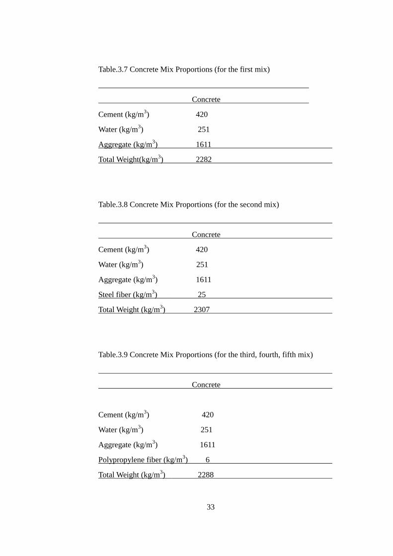
3.3 Concrete Mixtures
The procedure given by the American Concrete Institute, ACI 211, was followed to
calculate the mix design proportions.
Concrete mix proportions used in this experimental study are given in Table 3.7,
Table 3.8 and Table 3.9.
33
Table.3.7 Concrete Mix Proportions (for the first mix)
Concrete
Cement (kg/m3) 420
Water (kg/m3) 251
Aggregate (kg/m3) 1611
Total Weight(kg/m3) 2282
Table.3.8 Concrete Mix Proportions (for the second mix)
Concrete
Cement (kg/m3) 420
Water (kg/m3) 251
Aggregate (kg/m3) 1611
Steel fiber (kg/m3) 25
Total Weight (kg/m3) 2307
Table.3.9 Concrete Mix Proportions (for the third, fourth, fifth mix)
Concrete
Cement (kg/m3) 420
Water (kg/m3) 251
Aggregate (kg/m3) 1611
Polypropylene fiber (kg/m3) 6
Total Weight (kg/m3) 2288

34
Table 3.10 gives a summary of the information given in Table 3.9 and the unit
weights of concrete mixes were determined experimentally. The slumps of concrete
mixes were adjusted to 12 mm also the water/cement ratio of concrete mixes was 0.6.
Table.3.10 Characteristics of Fresh Concrete
Mixes Slump Air Unit
(cm) content (%) weight(kg/m³)
Steel Mesh 12 2.0 2265
Steel Fiber 11 3.0 2270
PP Fiber-1 11 3.3 2265
PP Fiber-2 12 4.0 2230
PP Fiber-3 12 4.0 2245
3.4 Tests on Fresh Concrete
Slump, unit weight and air content were the types of tests performed on concrete.
3.4.1 Slump Test
While concrete mixes were being prepared, a strict slump control was made for
batches, and slumps of concrete mixes were adjusted to exact values given in Table
3.10 values.
3.4.2 Unit weight of Fresh Concrete
Unit weight tests of concrete mixes were performed according to ASTM C 138. The
results were given in Table 3.10.

35
3.4.3 Determination of Air Content
Air contents of concrete mixes were determined by Pressure Method according to
ASTM C 231 and the results were given in Table 3.10.
3.5 Tests on Hardened Concrete
Compressive strength tests and plate tests were conducted on concrete specimens.
3.5.1 Compressive Strength Tests
Compressive strength tests of plain or fiber reinforced concrete specimens at the ages
of 7, 28 days were performed according to ASTM C 39. Cylindrical cores of 10 cm
in diameter and 20 cm in height were used for the tests. The results are tabulated and
discussed in Chapter 4.
3.5.2 Plate Tests
The plate tests were performed to investigate the toughness, ductility, load carrying
and energy absorption capacities of concrete mixes. The results are tabulated,
graphed and discussed in Chapter 4.
Firstly, the plates having dimensions of 600x600x100 mm were prepared according
to the specification. Then, the specimens were allowed to be cured and stored in
water for 7, 28 days immediately before testing.
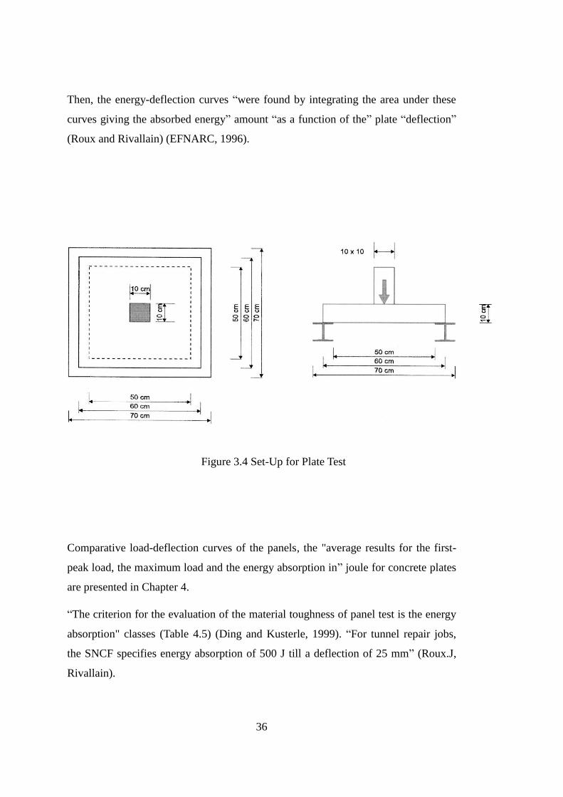
As can be seen from Figure 3.3, the prepared test panels for each mix were supported
on its four edges by a rigid metallic frame and center point load applied by using 40 t
Universal Testing machine through a contact surface of 100x100 mm. The rough side
of the panel was on the bottom during the test, i.e. the load was applied to the
spraying direction. The rate of deformation at the mid point was nearly 1.5 mm per
minute. Tests continued until a deflection of 25 mm was achieved at the center point
of the slab.
After that, the load-deformation curves were drawn for all mixes having four plates
each and comparative load-deflection curves were obtained as average results of the
tests.
36
Then, the energy-deflection curves “were found by integrating the area under these
curves giving the absorbed energy” amount “as a function of the” plate “deflection”
(Roux and Rivallain) (EFNARC, 1996).
Figure 3.4 Set-Up for Plate Test
Comparative load-deflection curves of the panels, the "average results for the first-
peak load, the maximum load and the energy absorption in” joule for concrete plates
are presented in Chapter 4.
“The criterion for the evaluation of the material toughness of panel test is the energy
absorption" classes (Table 4.5) (Ding and Kusterle, 1999). “For tunnel repair jobs,
the SNCF specifies energy absorption of 500 J till a deflection of 25 mm” (Roux.J,
Rivallain).

37
CHAPTER 4
TEST RESULTS AND DISCUSSIONS
In this chapter, results of the tests performed on reinforced hardened concrete will be
given and these results will be discussed extensively.
4.1 Comparison of the plates according to their performances
It can be seen from Figures 4.1 and 4.2 that the first peak and ultimate loads of steel
mesh are more than the other mixes. All mixes having decrease in load-carrying
capacities show unstable zone after the peak load. On the other hand, up to 25 mm
deflection, the area under the load deflection curve of the steel mesh is much higher
than other mixes causing steel mesh having also higher energy absorption capacity.
PP-2 showed more ductile behavior and has better load carrying capacity up to 25
mm deflection than other panels except steel mesh.
Steel fiber, PP-1 and PP-3 come subsequently with respect to absorption capacity
after steel mesh and PP-2.
Steel fiber and PP-2 show a small decrease in load carrying capacity between the
deflections of 1 mm and 2 mm after their peak load, but then they preserve their load
carrying capacities representing the stable and ductile behavior. At the end up to 25
mm deflection, the area under the load-deflection curve of PP-2 is higher than steel
fiber causing PP-2 having also higher energy absorption capacity. PP-3 shows the
least energy absorption capacity.

38
Figure 4.1 Comparison of Load-Deformation Graphs of the plate mixes for 7 days.
Figure 4.2 Comparison of Energy-Deformation Graphs of the plate mixes for 7 days.

39
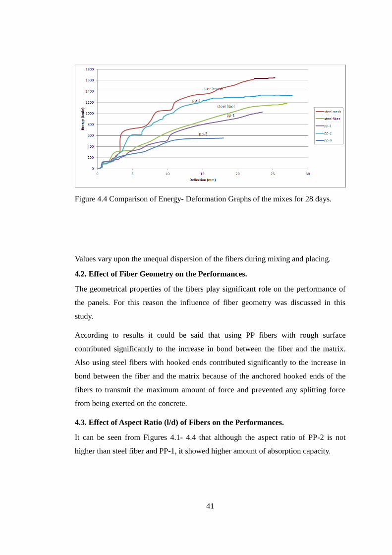
It can be seen from Figures 4.3 and 4.4 that the 7 day values increased approximately
from 10% to 30%. First peak and ultimate load of steel mesh are more than the other
mixes. On the other hand, up to 25 mm deflection, the area under the load deflection
curve of steel mesh is much higher than the other mixes causing steel mesh having
also higher energy absorption capacity. Also it can be seen from Figure 4.3 and 4.4
that the first peak and ultimate load of steel mesh are the maximum. After the first
cracking load, the load carrying capacities of all panels with fibers drop up to a
deflection of 2.5 mm and then, the load capacity of steel fiber panel continues to
decrease and PP panels remains stable or show little decrease till the last deflection.
But steel mesh indicating different behavior increases its load-carrying capacity and
reaches its ultimate value at the deflection of 3.5 mm and it shows much better load
carrying and energy absorption capacity than others although its load capacity
decreases after it’s ultimate load. Also, its energy absorption up to the deflection of
25 mm is nearly 1.5 times of steel fiber, PP-1, PP-2 and 3 times that of PP-3.
PP-2 again show more ductile behavior and has better load carrying and energy
absorption capacity up to 25 mm deflection than other panels except steel mesh.
Steel fiber, PP-1 and PP-3 come subsequently with respect to absorption capacity
after steel mesh and PP-2.
Steel fiber and PP-2 have similar load carrying capacities between the deflections of
15 mm and 25 mm.
Steel fiber, PP-2 and PP-1 show a decrease in load carrying capacity between the
deflections of 1 mm and 3 mm after their peak load but then they preserve their load
carrying capacities representing the stable and ductile behavior. At the end up to 25
mm deflection, the area under the load-deflection curve of PP-2 is higher than steel
fiber and PP-1 having also higher energy absorption capacity. PP-3 shows the least
energy absorption capacity.
On the other hand, as can be seen from Figures 4.1-4.4 for PP-2 and steel fiber
panels, increase in fiber content decreased the first cracking and ultimate load
capacities of them causing not so much increase in toughness and energy absorption
capacities. Values show variation upon the unequal dispersion of the fibers.

40
The main reason of steel mesh panels “having higher energy absorption capacity than
the other panels is that the bond and the friction stresses between the steel mesh and
the concrete matrix are greater” and the steel mesh has enough bond length that
provides better yielding and plastic deformation of it also increasing of the load
carrying and energy absorption capacity (Cengiz, 2001). In addition, the diameters of
steel mesh are 10 and 6 mm.
According to results, it can be said that using steel fibers which is hooked and having
high aspect ratio or PP fibers in concrete is considerably more advantageous than
using steel mesh in performance point of view especially for tunnel applications
where there are also many difficulties in application of steel mesh (Cengiz, 2001).
Figure 4.3 Comparison of Load- Deformation Graphs of the plate mixes for 28 days.
41
Figure 4.4 Comparison of Energy- Deformation Graphs of the mixes for 28 days.
Values vary upon the unequal dispersion of the fibers during mixing and placing.
4.2. Effect of Fiber Geometry on the Performances.
The geometrical properties of the fibers play significant role on the performance of
the panels. For this reason the influence of fiber geometry was discussed in this
study.
According to results it could be said that using PP fibers with rough surface
contributed significantly to the increase in bond between the fiber and the matrix.
Also using steel fibers with hooked ends contributed significantly to the increase in
bond between the fiber and the matrix because of the anchored hooked ends of the
fibers to transmit the maximum amount of force and prevented any splitting force
from being exerted on the concrete.
4.3. Effect of Aspect Ratio (l/d) of Fibers on the Performances.
It can be seen from Figures 4.1- 4.4 that although the aspect ratio of PP-2 is not
higher than steel fiber and PP-1, it showed higher amount of absorption capacity.

42
4.4. Effect of Fiber Addition on Compressive and Split Tensile Strength of
Concrete Mixes.
In this section the compressive and split tensile strengths of mixes will be compared
to evaluate the effect of fiber addition.
The compressive and split tensile strength results can be seen in Table 4.1. From this
table, it can be said that the compressive and split tensile strengths were little
influenced by addition of fiber for concrete mixes.
Therefore it can be concluded that for concrete mixes compressive and split tensile
strength is mainly controlled by concrete mix design.
Table.4.1 Compressive and Split Tensile Strength of Concrete Mixes
Mixes 7 day Compression 28 day Compression 7 day Split T. 28 day Split T.
Strength Strength Strength Strength
(MPa) (MPa) (MPa) (MPa)
Steel Mesh 30.2 37.5 2.9 3.2
Steel Fiber 30.3 35.0 3.3 3.4
PP Fiber-1 27.5 34.8 3.0 3.2
PP Fiber-2 28.2 38.0 2.7 3.8
PP Fiber-3 26.8 29.9 2.4 2.7
10x20 (dxh) cylindrical core compressive and split tension strengths at 7, 28 days
in MPa.

43
4.5. Comparison of the beams according to their performances
It can be seen from Figures 4.5 and 4.6 that the first peak and ultimate loads of steel
mesh are more than the other mixes. All mixes having decrease in load-carrying
capacities show unstable zone after the peak load. On the other hand, up to 25 mm
deflection, the area under the load deflection curve of PP-1 is much higher than other
mixes causing PP-1 having also higher energy absorption capacity.
Steel mesh showed more ductile behavior and has better load carrying capacity up to
25 mm deflection than other panels except PP-1.
PP-2, steel fiber and PP-3 come subsequently with respect to absorption capacity
after steel mesh and PP-1.
Steel fiber and PP-1 show a small decrease in load carrying capacity between the
deflections of 1 mm and 5 mm after their peak load, but then they preserve their load
carrying capacities representing the stable and ductile behavior. At the end up to 25
mm deflection, the area under the load-deflection curve of PP-1 is higher than steel
mesh causing PP-1 having also higher energy absorption capacity. PP-3 shows the
least energy absorption capacity.
Figure 4.5 Comparison of Load- Deformation Graphs of the beam mixes for 7 days.

44
Figure 4.6 Comparison of Energy-Deformation Graphs of the beam mixes for 7 days.
It can be seen from Figures 4.7 and 4.8 that the 7 day values increased approximately
from 10% to 30%. First peak and ultimate load of steel mesh are more than the other
mixes. On the other hand, up to 25 mm deflection, the area under the load deflection
curve of PP-1 is much higher than the other mixes causing PP-1 having also higher
energy absorption capacity.
Steel mesh show more ductile behavior and has better load carrying and energy
absorption capacity up to 25 mm deflection than other panels except PP-1.
PP-2, PP-3 and steel fiber come subsequently with respect to absorption capacity
after steel mesh and PP-1.
Steel fiber, PP-1 and PP-2 have similar load carrying capacities between the
deflections of 13 mm and 19 mm.
Steel fiber, PP-1, PP-2 and PP-3 show a decrease in load carrying capacity between
the deflections of 1 mm and 2 mm after their peak load but then they preserve their
load carrying capacities representing the stable and ductile behavior. At the end up to
25 mm deflection, the area under the load-deflection curve of PP-2 is higher than

45
steel fiber and PP-1 having also higher energy absorption capacity. PP-3 shows the
least energy absorption capacity.
On the other hand, as can be seen from Figures 4.5-4.8 for PP-1 and steel fiber
panels, increase in fiber content decreased the first cracking and ultimate load
capacities of them causing not so much increase in toughness and energy absorption
capacities. Values vary upon the unequal dispersion of the fibers.
Figure 4.7 Comparison of Load-Deformation Graphs of the beam mixes for 28 days.
Figure 4.8 Comparison of Energy-Deformation Graphs of the beam mixes for 28 days.

46
The load deflection graph illustrated in Figure 4.1 and 4.3 is “typical for a panel test
and it differs from the beam test” (Ding, 1998) because the beam is only subjected in
one direction but the plate is moving in two directions.
4.6. Failure Mechanisms of Panels.
There are differences between steel mesh panels and fiber reinforced panels from
performance point of view as mentioned before. It was seen that in this study that
there were also differences between failure mechanisms of the mixes.
Figures 4.9-4.13 show the failure patterns of the panels. It seems that steel mesh
panels failed in punching shear modes and showed flexural failure modes due to the
hardened concrete having tensile strength. Friction stresses and the bond between
steel mesh and concrete matrix increased the punching shear capacity by a little
amount although not having shear reinforcement.
Figure 4.9 Failure pattern of steel mesh panel.
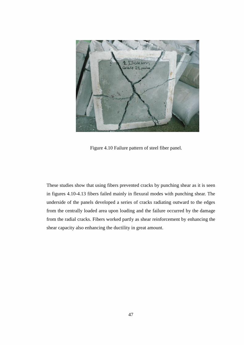
47
Figure 4.10 Failure pattern of steel fiber panel.
These studies show that using fibers prevented cracks by punching shear as it is seen
in figures 4.10-4.13 fibers failed mainly in flexural modes with punching shear. The
underside of the panels developed a series of cracks radiating outward to the edges
from the centrally loaded area upon loading and the failure occurred by the damage
from the radial cracks. Fibers worked partly as shear reinforcement by enhancing the
shear capacity also enhancing the ductility in great amount.

48
Figure 4.11 Failure pattern of PP-1 panel.
Figure 4.12 Failure pattern of PP-2 panel.
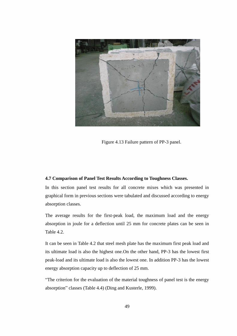
49
Figure 4.13 Failure pattern of PP-3 panel.
4.7 Comparison of Panel Test Results According to Toughness Classes.
In this section panel test results for all concrete mixes which was presented in
graphical form in previous sections were tabulated and discussed according to energy
absorption classes.
The average results for the first-peak load, the maximum load and the energy
absorption in joule for a deflection until 25 mm for concrete plates can be seen in
Table 4.2.
It can be seen in Table 4.2 that steel mesh plate has the maximum first peak load and
its ultimate load is also the highest one.On the other hand, PP-3 has the lowest first
peak-load and its ultimate load is also the lowest one. In addition PP-3 has the lowest
energy absorption capacity up to deflection of 25 mm.
“The criterion for the evaluation of the material toughness of panel test is the energy
absorption” classes (Table 4.4) (Ding and Kusterle, 1999).

50
Also by comparing Figures from 4.1 to 4.4 with Table 4.4 the results of achieving of
energy absorption classes according to related deflections can be obtained and it can
be seen in Table.4.3.
Table 4.2 Comparison of the Average Values of First Peak Load (kN), Ultimate Load
(kN), and Energy Absorption for Concrete Plates (28 days)
Mixes First Peak Ultimate Energy Absorption
Load (kN) Load (kN) (Joule)
Steel Mesh 80 115 1589.4
Steel Fiber 82 82 1149.5
PP Fiber-1 74 74 1016.3
PP Fiber-2 76 76 1242.3
PP Fiber-3 64 64 553
Table 4.3 Energy Absorption Classes with respect to Deflections for Concrete Mixes
(28 days)
Mixes Deflection (mm) Deflection (mm) Deflection (mm)
achieved class (a) achieved class (b) achieved class (c)
Steel Mesh 5.1 7 10.2
Steel Fiber 8.5 13 21
PP Fiber-1 11.5 17 22
PP Fiber-2 10.6 16.5 24
PP Fiber-3 19 - -

51
Table 4.4 Energy Absorption Requirements according to EFNARC (1996).
Toughness Class Energy Absorption for Deflection up to
25 mm in Joule
a 500
b 700
c 1000
It can be seen from Table 4.3 that steel mesh panel firstly achieved the energy
absorption class of (a), (b) and also (c). On the contrary, PP-3 panels lastly achieved
the energy classes. In general, it can be said that panels including steel fibers that had
hooked end and high aspect ratio showed good performance.
Apart from these polypropylene fibers showed good performance except PP-3.

52

53
CHAPTER 5
CONCLUSION& RECOMMENDATIONS
The experimental investigations were performed on steel mesh (SM), steel fiber (SF),
polypropylene fiber (PP)-reinforced concrete mixes to observe their performance
characteristics such as toughness, flexural ductility, energy absorption and load
carrying capacities, compressive behavior etc.
As a result of this study, the following conclusions can be written.
1. All types of fibers have the ability to increase mechanical properties of brittle
concrete.
Fiber addition improved toughness, flexural ductility, punching shear, energy
absorption capacity and load carrying capacity of concrete significantly.
2. The increase in fiber content did not enhance the load carrying and energy
absorption capacities for all types of panels. Although the amount of fibers that used
in SF is higher than PP-2, PP-2 showed better load carrying and energy absorption
capacity. According to these results mechanical properties of the fibers have more
effect on strength than the amount of fiber used.
3. The size, shape and geometry of the fibers are very important for fiber reinforced
concrete from performance point of view. Among the four types of fibers, PP-2 and
SF showed the best results from the mechanical point of view. It can be said that
using steel fibers with hooked ends in concrete contribute significantly to the
increase in bond between the fiber and the matrix because of the anchored hooked
ends of the fibers which make it available to use all parts of the fiber to transmit the
maximum amount of force. Also PP fibers that has smooth surface, disperse
uniformly in the concrete and showed best results with respect to flexural strength,
toughness, ductility, and load carrying capacity.

54
4. According to the results, it can be said that compressive strength of the mixes were
little influenced by fiber addition for all concrete mixes. Compressive strength is
mainly controlled by the concrete mix design and the compressive strength of the
concrete depends on the compressive strength of the matrix.
5. According to the performances of the mixes, it can be said that using steel fiber or
PP fiber can be more advantageous than using steel mesh in concrete for the
applications. Although steel mesh has many difficulties in application it showed the
best results with respect to toughness, flexural strength, ductility and the load
carrying capacity. Therefore the material to be used has to be selected according to
the importance degree of strength or easiness in application. Also it must be stated
that steel mesh gave the best results in laboratory conditions. In the field fibers can
give better results than steel mesh. Lining quality of steel mesh is poor and there is
no uniform bond between concrete and rock in the field. Irregular mesh positions and
low qualified shadow areas behind the wire can lower the toughness of steel mesh.
6. This investigation showed that using fibers in concrete prevented cracks by
punching shear and the fiber usage greatly improved the punching shear capacity
with ductility according to the working of fibers which are distributed mainly two or
three dimensionally as shear reinforcement. Panels with fiber failed mainly in
flexural modes with some punching shear, panels with steel mesh failed mainly in
punching shear modes and showed also flexural failure behaviors.
7. Polypropylene fibers can be as effective as steel fibers.
8. This investigation showed that the panel test works better for determining
toughness than the beam test. The results of the beam tests were compared with the
plate test to determine the effectiveness of using beam tests for toughness instead of
plate test. The results of the beam tests did not show parallelism with the results of
the plate tests.

55
The main purpose to apply panel tests and beam tests is to evaluate the performances
of reinforced concrete mixes such as toughness, ductility, energy absorption and load
capacity, compressive strengths and split tension strengths etc. According to the
results obtained from the study the following recommendations are made for further
investigations.
1- In this experimental study, the experimental investigations were performed on
steel mesh, steel fiber and high performance polypropylene fiber-reinforced concrete
panels and beams for 7, 28 days. Further studies should be performed on the
specimens at very early age. By this way, the evaluation of the performances can be
made for early strength developments.
2- The energy absorption capacity and flexural toughness of the specimens were
obtained in this study by integrating the area under load-deflection curve of them.
Additional tests can be performed to investigate the compressive behavior of the
same materials by using stress-strain relationships. By this way, compressive
toughness of the mixes can be obtained.
3- Further studies should cover different types of reinforcements other than steel
mesh, steel fiber and polypropylene fiber to get the best efficiency from concrete. For
example coconuts and glass particles can be used to investigate toughness behavior.
4- Concrete panels reinforced with steel mesh, steel fiber, polypropylene fiber were
tested in this research to investigate the effects of using them. Additional tests can be
made for hybrid steel-polypropylene fiber reinforced concrete containing hooked
steel fibers having high aspect ratio to improve the performance.
5. Polypropylene fibers can be used in water structures with respect to corrosion.
Also it can be disadvantageous to use polypropylene fibers in the case of fire.

56

57
REFERENCES
ACI Committee 544, (1998) Guide for specifying, Proportioning, Mixing, Placing,
and Finishing Steel Fiber Reinforced Concrete, Farmington Hills, Michigan:
American Concrete Institute.
ACI Committee 544, (2002) State of the Art-Report on Fiber Reinforced Concrete,
Farmington Hills, Michigan: American Concrete Institute.
ASTM C1399/C1399 M-10 Standard Test Method for Obtaining Average Residual
Strength of Fiber-Reinforced Concrete, West Conshohocken, PA: ASTM
International.
Alani, M.A. & Beckett, D. (2013) Mechanical Properties of a large scale synthetic
fiber reinforced concrete ground slab, Construction and Building Materials 41, 335-
344.
Ashish, D. & Banthia, N. (1998) Influence of high reactivity metakaolin and silica
fume on the flexural toughness of high performance steel fiber-reinforced concrete,
ACI Materials Journal 95, 284-292.
Ayan, E. & Saatçioğlu, Ö. & Turanli, L. (2011) Parameter optimization on
compressive strength of steel fiber reinforced high strength concrete, Construction
and Building Materials 25, 2837-2844.
Campione, G. & Mangiavillano, M.L. (2008) Fibrous reinforced concrete beams in
flexure: Experimental investigation, analytical modeling and design considerations,
Engineering Structures 30, 2970-2980.
Cengiz, O. & Turanli,L. (2004) Comparative evaluation of steel mesh, steel fiber and
high performance polypropylene fiber reinforced shotcrete in panel test, Cement &
Concrete Research 34, 1357-1364.
Cengiz, O. (2001) Comparative evaluation of steel mesh, steel fiber and high
performance polypropylene fiber reinforced shotcrete in panel test, M.S. Thesis.

58
Chen, L. & Mindess, S. & Morgan, R. (1994) Specimen Geometry and Toughness of
Steel-Fiber Reinforced Concrete , Journal of Materials in Civil Engineering 6, 529-
541.
Chunxiang, Q. & Patankuni, I. (1999) Properties of high strength steel fiber
reinforced concrete beams in bending, Cement & Concrete Composites 21, 73-81.
Ding, Y. & Kusterle, W (2000) Compressive stress-strain relationship of steel-fiber
reinforced concrete at early age, Cement & Concrete Research 30, 1573-1579.
Ding,Y. & You, Z. & Jalali, S.(2011) The composite effect of steel fibers and stirrups
on the shear behavior of beams using self consolidating concrete, Engineering
Structures 33, 107-117.
Ding. Y. (2011) Investigations into the relationship between deflection and crack
mouth opening displacement of SFRC beam, Construction and Building Materials 25,
2432-2440.
Ding, Y. & Kusterle, W. (1999) Comparative study of steel fiber reinforced concrete
and steel mesh reinforced concrete at early ages in panel tests, Cement and Concrete
Research 29, 1827-1834.
Erdoğan, T.Y. (2002) Materials of Construction, Ankara: METU Press.
Erdoğan, T.Y. (2003) Beton, Ankara: METU Press.
European Federation of Producers and Applications of Specialist Products for
Structures, European specification for sprayed concrete, EFNARC, Loughborough
University, 1996, pp.8-10.
Felekoğlu, B. & Türkel, S. & Altıntaş, Y. (2007) Effects of Steel Fiber Reinforcement
on surface wear resistance of self-compacting repair mortars, Cement & Concrete
Composites 29, 391-396.
Fuente, A. & Aguado, A & Molins, C. & Armengou,J. (2011) Innovations on
components and testing for precast panels to be used in reinforced earth retaining
walls, Construction and Building Materials 25, 2198-2205.

59
Gopalartnam, V.S. & Gettu,R. (1994) On the characterization of Flexural Toughness
in Fiber Reinforced Concretes, Cement & Concrete Composites 17, 239-254.
Jovicic, V. & Sustersic, J.& Vukelic, Z. (2009) The application of fiber reinforced
shotcrete as primary support for a tunnel in flysch., Tunneling and Underground
Space Technology 24, 723-730.
Kormeling, H.A. & Reinhardt H.W & Shah S.P.(1980) Static and fatigue properties
of concrete beams reinforced with continuous bars and with fibers, Journal
Proceedings 77, 36-43.
Kurihara,N. & Kunieda, M. & Kamada, T.& Uchida, Y. &Rokugo, K.(2000) Tension
softening diagrams and evaluation of properties of steel fiber reinforced concrete,
Engineering Fracture Mechanics 65, 235-245.
Leung, K.Y. & Lai, R.& Lee, Y.F. (2005) Properties of wet-mixed fiber reinforced
shotcrete and fiber reinforced concrete with similar composition, Cement & Concrete
Research 35, 788-795.
Luo, X. & Sun. W, & Chan, Y.N.(2000) Characteristics of high performance steel
fiber reinforced concrete subject to high velocity impact, Cement & Concrete
Research 30, 907-914.
Lok, T.S. & Xiao,J.R. (1999) Steel-fiber reinforced concrete panels exposed to air
blast loading, Proc.Instn.Civ.Eng.Structs. & Bldgs 134, 319-331.
Morgan, D.R. and Fekete, A., Steel Fiber Reinforced Shotcrete for Underground
Support.
Indian Journal of Rock Mechanics and Tunnelling Technology, Vol. 4, No.1, March,
1998, pp.1-41.
Morgan, D.R. Chen,L.. Beaupre D.,Toughness of Fiber Reinforced Shotcrete ASCE
Shotcrete For Underground Support VII, Telfs, Austria, 1995, pp.66-87.
Morgan, D.R. McAskill, N., Richardson, B.W. and Zellers, R.C., A Comparative
Evaluation of Plain, Polypropylene Fiber, Steel Fiber and Wire Mesh Reinforced
Shotcrete Transportation Research Record 1226, Washington, D.C., 1989, pp.78-87.

60
Morgan, D.R. and Rich, L.,High Volume Synthetic Fiber Reinforced Shotcrete First
Annual Synthetic Fiber Reinforced Concrete Symposium, Orlando, Florida, January
16, 1998, pp.115-132.
Morgan, D.R. Heere, R., McAskill, N. And Chan,C.,System Ductility of Mesh and
Fiber Reinforced Shotcrete Seminar on Advances in Shotcrete Technology, American
Concrete Institute Spring Convention, Chicago, March 17, 1999, pp.36.
Morgan, D.R. Heere, R., McAskill, N. And Chan,C., Comparative Evaluation of
SystemDuctility of Mesh and Fiber Reinforced Shotcrete ASCE Shotcrete For
Underground Support VIII, Sao Paulo, April 11-15, 1999, pp.216-239.
Mehta, P.K.& Monteiro, P.J.(2006) Concrete : Microstructure, Properties and
Materials (3rd
ed) New York: Mc Graw-Hill.
Nataraja, M.C.& Dhang, N.&Gupta, A.P.(1999) Stress-strain curves for steel-fiber
reinforced concrete under compression, Cement & Concrete Composites 21, 383-
390.
Nataraja, M.C.& Dhang, N.&Gupta, A.P.(1999) Statistical variations in impact
resistance of steel-fiber reinforced concrete subjected to drop weight test, Cement &
Concrete Research 29, 989-995.
Nataraja, M.C. & Dhang, N. & Gupta, A.P.(2000) Toughness Characterization of
Steel-Fiber Reinforced Concrete by JSCE approach, Cement & Concrete Research
30, 593-597.
Neville, A.M. (2003) Properties of Concrete (4th
ed.) Harlow, England, Prentice Hall.
Neville, A.M. & Brooks, J.J.(2010) Concrete Technology (2nd
ed.) Harlow, England,
Prentice Hall.
Okuyucu, D. & Uzal, B. & Turanlı, L.& Tankut, T (2011) Some Characteristics of
fiber-reinforced semi-lightweight concrete with unexpanded perlite, Magazine of
Concrete Research 63, 837-845.
Pigeon, M. & Cantin, R. (1998) Flexural Properties of steel fiber-reinforced concrete
at low temperatures, Cement & Concrete Composites 20, 365-375.

61
Qian, C.& Indubhushan, P. (1999) Properties of high strength steel fiber reinforced
concrete beams in bending, Cement & Concrete Composites 21, 73-81.
Qian, C.X. & Stroeven, P. (2000) Development of hybrid polypropylene steel fiber
reinforced concrete, Cement & Concrete Research 30, 63-69.
Rafeq, A.S. & Gupta, A. & Krishnamoorthy, S. (2000) Influence of Steel Fiber in
Fatigue Resistance of Concrete in Direct Compression, Journal of Materials in Civil
Engineering 12, 172-179.
Rambo, D.A.S. & Silva,A.& Filho,R. (2014) Mechanical behavior of hybrid steel-
fiber self consolidating concrete: Materials and structural aspects, Materials and
Design 54, 32-42.
Roux J., Cheminias J., Rivallain Get Mourand C., Durand G. Plate Test, Realized by
French Railway Company (SNCF), together with the Alpes Essais Laboratory of
Grenoble (a slab test developed to characterize SFRC).
Tan, K. & Paramasivam, P(1994) Punching Shear strength of steel fiber reinforced
concrete slabs, Journal of Materials in Civil Engineering 6, 240-253.
Trottier, J.F. & Banthia, N. (1994) Toughness Characterization of Steel-Fiber
Reinforced Concrete, Journal of Materials in Civil Engineering 6, 264-289.
Toutanji, H. & Bayasi, Z.(1998) Effects of Manufacturing Techniques on the Flexural
Behavior of Steel Fiber Reinforced Concrete, Cement & Concrete Research 28, 115-
124.
Yin, W. & Hsu, T.C. (1995) Fatigue behavior of steel fiber reinforced concrete in
uniaxial and biaxial compression, Materials Journal 92, 71-81.
Zhang,J. & Stang,H. & Li,C. (2000) Experimental study on crack bridging in FRC
under uniaxial Fatigue tension, Journal of Materials in Civil Engineering 12, 66-73.
Zollo, R.F. (1997) Fiber Reinforced Concrete: an Overview after 30 Years of
Development, Cement & Concrete Composites 19, 107-122.