comparative study and performance analysis of porous circular pin fin · pdf...
TRANSCRIPT

Proceedings of the International Conference on Mechanical Engineering and Renewable Energy 2017
(ICMERE2017) 18 – 20 December, 2017, Chittagong, Bangladesh
ICMERE2017-PI-200
© ICMERE2017
.
1. INTRODUCTION Driving energy in a system of nature always allows to
flow until equilibrium is reached. Heat leaves the warmer
body or the hottest fluid, as long as there is a temperature.
A heat exchanger follows this principle in its endeavor to
reach equalization. With a plate type heat exchanger, the
heat penetrates the surface, which separates the hot
medium from the cold one very easily. It is therefore
possible to heat or cool fluids or gases which have
minimal energy levels. The theory of heat transfer from
one media to another, or from one fluid to another, is
determined by several basic rules. Heat transfer by
convection between solid surface and the surrounding
fluid can be increased by increasing heat transfer area by
attaching to the surface thin strips of metals called fins.
In the study of heat transfer, a fin is a surface that extends
from an object to increase the rate of heat transfer to or
from the environment by increasing convection. The
study of extended surface heat transfer in most of the
cases comprises two factors that may conveniently be
separated. One factor is only the movement of heat
within the fin by conduction. The other factor considers
how the fin exchanges heat with the surroundings. The
amount of conduction, convection or radiation of an
object determines the amount of heat it transfers. The
heat transfer can be increased by increasing the
convection heat transfer coefficient or increasing the
surface area of an object or increasing the temperature
difference between the object and the environment.
Adding a fin to an object increases the surface area
becomes an economical solution to heat transfer
problems. Finned surfaces are manufactured by
extruding, welding, or wrapping a thin metal sheet on a
surface. Heat transferred through the fin can be take
place by conduction, convection and radiation.
Sometimes heat transferred by radiation is neglected.
Heat transfer rate of pin fin is largely affected by the fin
height (H/d), and other affecting factors include the heat
transfer rate of pin fin is largely affected by the fin height
(H/d), and other affecting factors include the velocity of
fluid flow, the thermal properties of the fluid, the
cross-sectional shape of the pin-fins like perforation,
the relative inter-fin pitch, the velocity of fluid flow,
the thermal properties of the fluid, the cross-sectional
shape of the pin-fins like perforation, the relative
inter-fin pitch, the arrangement of the pin-fins like
in-line, staggered arrangement and others. Several
research works have been carried out to augment heat
transfer by increasing heat transfer area from the
beginning of the twentieth century by several scientists,
Gerald Vanfossen and Beard-Ann Brigham[1] studied
the heat transfer by short pin-fins in staggered
arrangements. According to their study, longer pin fins
(H/d = 4) transfer higher heat than shorter pin-fins (H/d
= ½ and 2) and the array-averaged heat transfer with
Abstract:-Heat transfer enhancement has become a great deal as the advancement of new technology. In
this project, convective heat transfer by using porous circular pin fin array has been investigated. The main
objective was to bring a new version of fin that would provide maximum cooling performance in heat
engine taking less cost energy to consume. Porous circular shape of aluminum fin having fin height (h) =70
mm, base diameter (d) =10.2 mm, fin spacing (s) = 35 mm, hole diameter (d2) = 4 mm, hole depth (H) =
10.2 mm of staggered arrangement has been selected for better performance. There are seven pin fins have
used in this experiment. Heat transfer coefficient for free convection has been investigated. A comparative
study of porous circular pin fin efficiency and circular pin fin efficiency has been calculated. This work has
compared with the previous work done using circular pin fin shape without pores. It has found that with the
same power for porous circular pin fin array has 12% higher efficiency and it has 6.02% higher heat transfer
coefficient and material usage reduced 36.78% materials cost reduction 35% than existence. Heat transfer
coefficient was increased with the increase of temperature difference between the walls and ambient.
Keywords: Circular pin fin, heat transfer coefficient, fin efficiency, fin effectiveness, free convection.
COMPARATIVE STUDY AND PERFORMANCE ANALYSIS OF POROUS
CIRCULAR PIN FIN ARRAY
Md Zahid Hasan
1, Dr. Jamal Uddin Ahamed
2,
3Md. Hedayet Ullah
3.
Department of Mechanical Engineering, Chittagong University of Engineering and Technology, Bangladesh

© ICMERE2017
eight rows of pin-fins slightly exceed that with only four
rows.Their results also showed that the mean heat
transfer coefficient on the pin surface would around
35% greater than that on the end walls. Metzger et al.
[2] investigated the impacts of pin-fin geometry and
array orientation on the heat transfer and the pressure
loss in pin-fin arrays. According to their results, the use
of cylindrical pin-fins with an array orientation between
staggered and in-line can sometimes favour the heat
transfer, while substantially reducing pressure. Yusuf et
al. [3] showed rectangular shape of fin more efficient
than parabolic shape. Ramiz F. Babus’Haq et al. [4]
reported that the optimal ratio of the inter-fin pitch to
the pin fin diameter in the transverse direction was
2.04 for all pin-fin systems. However,the optimal ratios
in the longitudinal direction were 1.63, 1.71 and 1.95 for
poly tetra fluro-ethane pin-fins, mild-steel pin-fins and
duralumin pinfins respectively. Mohammad Shariar
Hossain et al. [5] showed that pin fin array of cylindrical
shape would more efficient than other types of
fins.Khaled et al.[6] performed his work in which that
had shown that conical pin fin was 12.16% more
efficient than that of other fin in heat rejection.A
conical porous pin fin array was designed flat plate wall.
The objective of this experimental study was to
investigate the heat transfer coefficient, fin efficiency
and fin effectiveness for free convection using porous
pin fin array based on the experimental results. These are
Transfer of heat was considered as one
dimensional flow.
During the experiment, no heat was
generated internally .
Heat transfer by radiation was neglected.
Across the whole surfacearea of the fin,
convection was considered uniform.
2. EXPERIMENTAL FACILITIES
2.1 Experimental Apparatus
To perform the experiment properly, several material
were used. Aluminum metal was used to construct
the pin fin array. One multi meter was usedfor
measuring current flow through the base, voltage
regulator for regulate voltage supply at a
particular heat supply, a thermocouple for measuring
fin temperature at base and surface at different
location.Author used insulator to reduce heat loss
from the base box to the surroundings. G.I. sheet,
asbestos and Aluminum alloy were also used in this
experiment.
2.2 Test Section
The test section consist of an array of seven porous
circular shape of aluminum fin having fin height (h)
=70 mm, base diameter (d) =10.2 mm and fin
spacing (s) =35 mm of staggered arrangement were
used. Figure 1 represents the graphical illustration of
the pin fin array which is drawn with the helpof
SOLID WORKS. Figure 2 shows the schematic
diagram of the experiment and Figure 3
represents the whole experiment set up and the test
section that was used to rub the experiment. The
experiment was conducted in the heat engine
laboratory of CUET.
In order to make easy experiment, data collections,
comparison and analysis, some assumption were made
in this experimental process which created some
limitations in the experimental results.
Fig 1: Porous circular pin fin arrangement\
Fig 2 : Schematic diagram assemble of extended surface
with electrical console.
Fig. 3: Experimental set-up

© ICMERE2017
3. MATHMATICAL DATA REDUCTION
The experimental data were used to determine
convection heat transfer coefficient, fin efficiency
and fin effectiveness for free convection. By
evaluating this three parameters, fin performance was
measured. Total amount of heat supplied was
calculated from Eq(1)
Q=VIcos …………….. (1)
Where V is voltage supplied, I is current and Cosθis
Power factor ≈0.8 ( for this experiment).
From Eq (2), the rate of convection heat transfer from
the extended surface was obtained and coefficient of
convective heat transfer was evaluated from Eq (3).
Q = h AH(tH-tA )+ℎ ( tFAV−tA ) (2)
h =
(3)
Where h is the convection heat transfer coefficient
(assumed constant), AHis the area of heated wall only,
AF summed area of all fins, tHis heated wall temperature
and tFAV is the average temperature along the length of
fins which may be approximated as meantemperature of
three temperature measured along length.
Heat transfer through pin fin was calculated as,
QF = h AF(tFAv-tA) …………………………. (4)
Where tA is the ambient temperature.
Fin performance can also be characterized by fin
efficiency.This is the ratio of the fin heat transfer rate
to the heat transfer rate of the fin if the entire fin were
atthe base temperature. Efficiency of the fin was
calculated by
ηf =
× 100…………………………. (5)
Fin efficiency will always be less than one.This is
Because assuming the temperature throughout the fin
is at the base temperature would increase the heat
transfer rate.
The performance of the fins is judged on the basis of
the enhancement in heat transfer relative to the no -fin
case. Performance of fins expressed in terms of
the fin effectiveness. It is the ratio of the fin heat
transfer rate to the heat transfer rate of the object if it
had no fin. The effectiveness of fin was calculated by
Effectiveness,
=
f=
=
………….. (3.5)
4 RESULTS AND DISCUSSINS
4.1 Heat Transfer Coefficient
Figure shows the change of heat transfer
coefficient with the increase of temperature
difference between the wall and ambient
temperature for porous pin fin array. Along with
enlarge surface area higher temperature
difference helps heat transfer rapidly.
Fig. 4: Temperature difference vs. heat transfer
Coefficient
From the above it is observed that, it is observed if
temperature difference heat transfer would increase
ultimately heat transfer coefficient would increase with
the increase of the temperature difference between wall
and ambient for free convection.
4.2 Fin Efficiency
Efficiency of the fin for porous conical pin fin array
Also increased as heat transfer coefficient increases.
Figure depicts the increase of efficiencywith the
increases of temperature difference between wall and
ambient.
Fig. 5: Temperature difference vs. efficiency
4.3 Fin Effectiveness
0
5
10
15
20
75 80 85 90 H
eat
tran
sfer
co
effi
cien
t 𝑊
∕𝑚² ℃
Temperature diefference between wall &
ambient(℃)
0
5
10
15
20
0 20 40 60 80 100
Effi
cien
cy (
%)
Temperature difference between wall …

© ICMERE2017
Fin effectiveness is another important parameter to
evaluate fin performance. Figure (6) shows the increase
of fin effectiveness with the change of the difference
between wall and ambient temperature. As Effectiveness
is increases this fin would be efficient in practical
purposes .
Fig. 6: Temperature difference vs. effectiveness
.
Table 1: Data of heat transfer coefficient, fin
efficiency and effectiveness
Test
no.
Free convection
h
(W/m2 °C)
ɳ
(%)
f QF
(watt)
1 76.15 66.67 13.33 7.85
2 78.04 81.25 16.25 11.62
3 86.25 83.33 16.67 14.63
4.4 Performance Evaluation.
The present result obtained from porous circular pin fin
array was compared with the nonporous circularpin fin
array.It is evident from this experiment that,porous
circular pin fin is more efficient than nonporous
circular pin fin array.From the result it was shown that
efficiency was increased relative to nonporous circular
pin fin array by 12% in free convection.Theheat transfer
coefficient was improved by 5.16% for porous conical
pinthan that of non-porous pin. Fin effectiveness also
increased by 11.1% for porous circular pin. Khaled et al.
[6] reported that, cylindrical pin fin array is 12.16% less
efficient than circular pin fin array. Figure (7) shows the
relation between the heat transfer coefficient and power
supply for porous and nonporous circular pin fin
array respectively. It had been shown that for any
amount of power supply,porous circular fin had the
higher heat transfer coefficient compared with
nonporous pin. Figure (8)
representsthe variation of efficiency for different
power input for porous and nonporous conical fin. It
can be seen that porous fin was more efficient for
every unit of power supply and the difference between
the efficiency was very high.
Fig. 7: Comparison of heat transfer coefficient
between porous and Non-porous circular pin fin.
Fig. 8: Comparison between the efficiency (ηf%) of
Porous and Non-porous circular pin fin
Fig. 9: Comparison of effectiveness between porous
and Non-porous pin fin
5 CONCLUSION
An experimental study was performed to investigate the
0
5
10
15
20
0 5 10 15 20
Effe
ctiv
enes
s ,𝞮
Temperature difference between wall …
0
50
100
0 10 20 30 40
He
at t
ran
sfe
r co
eff
icie
nt.
(W/m
2 °
k)
Power supply (Watt)
Porous Non-porous
21.53 26.8 33.44
60 71.42 75 66.67 81.25 83.25
0
50
100
1 2 3
Efficiency vs Power supply
Power Supply Non-porous Porous
13.33
16.25
16.67
12
14.28
15
0 5 10 15 20
21.528
26.8
33.44
Effectiveness
Po
wer
su
pp
ly (
wat
t)
Non-porous Porous
© ICMERE2017
performance of seven circular pin fin
array.Theseexperimental results were compared with a
porouscircular pin fin array for free convection heat
transfer process. The use of porous shape into the conical
pin fin provided significant augmentation of heat transfer
compared with non-porous fin.Based on the
experimental results, some key outcomes of this
experiment can be listed as follows:
The porous circular pin fin offered a
significant improvement in the case of heat
transfer coefficient, fin efficiency and fin
effectiveness.
The heat transfer coefficient was improved
by 6.02 % for porous circular pin than that of
non-porous pin.
Fin effectiveness was increased by 11.1%
for porous circular pin.
Efficiency was enhanced relative tonon porous
circular pin fin array by 12% in free
convection.
ACKNOWLEDGEMENT
The author would like acknowledge Chittagong
University of Engineering and Technology (CUET)
for their support in this research work.
REFERENCES
[1] B. Sahin, A. Demir “Performance analysis of a heat
exchanger having perforated square fins”,
ELSEVIER, Applied Thermal Engineering 28 (2008)
621–632
[2] D.E. Metzger, C.S. Fan, S.W. Haley, “Effects of
pin shape and array orientation on heat transfer and
pressure loss in pin fin arrays”, J. Eng. Gas Turbines
Power 106 (1984) 252–257
[3] S. M. Yusuf, “Design and fabrication of fin array
of rectangular shape” BSc. Thesis paper, Chittagong
University of Engineering and Technology (CUET),
2007
[4] R.F. BabusHaq, K. Akintunde, S.D. Probert,
“Thermal performance of a pin-fin assembly”, Int. J.
Heat Fluid Flow 16 (1995) 50–55.
[5] M.S Hossain,“Design and fabrication of cylindrical
pin fin array” BSc. Thesis paper, CUET,
2013
[6] KhaledurRahman, “Design and fabrication of
conical pin fin array” BSc. Thesis paper. Chittagong
University ofEngineering and Technology (CUET),
2014
[7] Md. Yunus Ali , “Design and fabrication of
porousconical pin fin array” BSc.Thesis paper.
Chittagong University of Engineering and Technology
(CUET), 2015
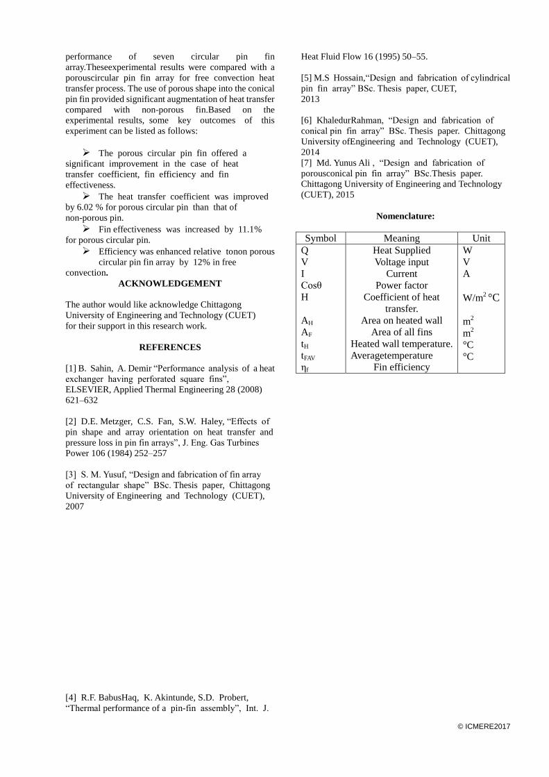
Nomenclature:
Symbol Meaning Unit
Q
V
I
Cosθ
H
AH
AF
tH
tFAV
ηf
Heat Supplied
Voltage input
Current
Power factor
Coefficient of heat
transfer.
Area on heated wall
Area of all fins
Heated wall temperature.
Averagetemperature
Fin efficiency
W
V
A
W/m2 °C
m2
m2
°C
°C