comparative study of power converter topologies and...
TRANSCRIPT

1
R. Melício a,b, V.M.F. Mendes c, J.P.S. Catalão a,b,*
a Department of Electromechanical Engineering, University of Beira Interior, R. Fonte do Lameiro, 6201-001 Covilha, Portugal
b Center for Innovation in Electrical and Energy Engineering, Instituto Superior Técnico, Technical University of Lisbon, Av. Rovisco Pais, 1049-001 Lisbon, Portugal
c Department of Electrical Engineering and Automation, Instituto Superior de Engenharia de Lisboa, R. Conselheiro Emídio Navarro, 1950-062 Lisbon, Portugal
Received 6 March 2010; received in revised form 3 October 2010
Abstract Power converters play a vital role in the integration of wind power into the electrical grid. Variable-speed wind turbine generator systems have a considerable interest of application for grid connection at constant frequency. In this paper, comprehensive simulation studies are carried out with three power converter topologies: matrix, two-level and multilevel. A fractional-order control strategy is studied for the variable-speed operation of wind turbine generator systems. The studies are in order to compare power converter topologies and control strategies. The studies reveal that the multilevel converter and the proposed fractional-order control strategy enable an improvement in the power quality, in comparison with the other power converters using a classical integer-order control strategy. © 2010 Elsevier Ltd. All rights reserved. Keywords: Wind energy; Power converters; Transient analysis; Power quality
1. Introduction
Wind power industry and the construction of wind farms are undergoing rapid development [1,2]. In
Portugal, the total installed renewable energy capacity reached 9321 MW in June 2010, of which wind
power capacity is responsible for 3802 MW, and continues growing.
As wind energy is increasingly integrated into power systems, the stability of already existing power
systems is becoming a concern of utmost importance [3]. Also, network operators have to ensure that
consumer power quality is not compromised. Hence, the total harmonic distortion (THD) should be kept
as low as possible, improving the quality of the energy injected into the electrical grid [4]. The new
technical challenges emerging due to increased wind power penetration imply research of more accurate
modeling and control of wind turbine generator (WTG) systems.
* Corresponding author. Tel.: +351 275 329914; fax: +351 275 329972.
E-mail address: [email protected] (J.P.S. Catalão).
Comparative study of power converter topologies and control strategies for the harmonic performance of
variable-speed wind turbine generator systems

2
Power converters play a vital role in the integration of wind power into the electrical grid [5]. Power
converters allow for variable-speed operation of the wind turbine [6-8], and enhanced power extraction
[9]. The use of power electronics components has resulted in the creation of extra degrees of freedom
thereby making it possible to implement more complex control algorithms and thus allowing the
optimization of the performance of a wind turbine [10].
The variable-speed WTG systems are implemented with either doubly fed induction generators
(DFIGs) [11] or full-power converters. At the moment, substantial documentation exists on modeling and
control issues for the DFIG wind turbine. But this is not the case for wind turbines with full-power
converter and permanent magnet synchronous generator (PMSG) [12]. Indeed, permanent magnet
machines appear more and more promising, having higher ratio of power to weight, reliability, and
efficiency than electrically excited machines [13].
In this paper, a variable-speed WTG system is considered with PMSG and three power converter
topologies: matrix, two-level and multilevel. Also, a fractional-order control strategy is proposed.
Accordingly, comprehensive simulation studies are carried out in order to adequately assess the harmonic
behavior of the electric current injected into the electrical grid, taking into account three power converter
topologies and both fractional-order and integer-order controllers.
This paper is organized as follows. Section 2 presents the modeling for the WTG system with different
topologies for the power converters, namely matrix, two-level and multilevel converters. Section 3
provides the fractional-order control strategy. Section 4 presents the harmonic assessment by Discrete
Fourier Transform (DFT) and THD. Section 5 provides the simulation results. Finally, Section 6 outlines
the conclusions.

3
Nomenclature
tP Mechanical power of the wind turbine.
Air density.
A Area covered by the rotor blades.
u Wind speed value upstream of the rotor.
pc Power coefficient.
Pitch angle of the rotor blades.
Tip speed ratio.
t Rotor angular speed at the wind turbine.
tJ Moment of inertia for the rotor of the wind turbine.
tT Mechanical torque.
dtT Resistant torque in the wind turbine bearing.
atT Resistant torque in the hub and blades due to the viscosity of the airflow.
tsT Torque of the torsional stiffness.
g Rotor angular speed at the generator.
gJ Moment of inertia for the rotor of the generator.
dgT Resistant torque in the generator bearing.
agT Resistant torque due to the viscosity of the airflow in the generator.
gT Electric torque.
fi Equivalent rotor current.
M Mutual inductance.
p Number of pairs of poles.
di , qi Stator currents.
dL , qL Stator inductances.
dR , qR Stator resistances.
du , qu Stator voltages.
nR Resistance of the electric grid.
nL Inductance of the electric grid.
fku Voltage at the filter.
ku Voltage at the electric grid.

4
2. Modeling 2.1 Wind turbine
The mechanical power tP of the wind turbine is given by:
pt cAuP 3
21 (1)
The computation of the power coefficient pc requires the use of blade element theory and the
knowledge of blade geometry. These complex issues are normally empirical considered. In this paper, the
wind turbine used corresponds to the one with the numerical approximation developed in [14], where the
power coefficient is given by:
i
ip ec
4.1814.2 2.13002.058.015173.0
(2)
where
)1(003.0
)02.0(1
1
3
i (3)
The power coefficient is a function of the pitch angle of rotor blades and of the tip speed ratio ,
which is given by:
uDwtλ
2 (4)
From (2), for a null pitch angle, the maximum power coefficient and the optimal tip speed ratio are
respectively: 4412.0max pc ; 057.7opt .
The mechanical torque tT of the wind turbine is given by:
t
tt w
PT (5)
This mechanical torque is responsible for the movement of the mechanical drive train.

5
2.2 Mechanical drive train
A way to model a mechanical drive train of a WTG system is to model the rotor as a number of
equivalent discrete masses connected together by springs and dampers. When the simulated applications
are limited to the impact of wind fluctuations, it is usually sufficient to consider the mechanical drive
train as a single-mass shaft model because shaft oscillations of the WTG system are not reflected to the
grid due to the fast active power control [15]. However, when the system response to heavy disturbances
is analyzed, the rotor must be approximated by at least a two-mass model [16]. One mass represents the
wind turbine moment of inertia, and the other mass represents the generator moment of inertia.
The equations for modeling the mechanical drive train are given by:
)(1
tsatdttt
t TTTTJdt
d
(6)
)(1
gagdgtsg
g TTTTJdt
d
(7)
Hence, a two-mass model for the mechanical drive train, given by Eqs. (6) and (7), is considered in this
paper.
2.3 Generator
The generator considered in this paper is a PMSG. The equations for modeling a PMSG can be found
in the literature [17]. Using the motor machine convention, the following equations in the dq-plane, based
on Park (d-q) transformation, are considered:
][1
ddqqgdd
d iRiLpuLdt
di (8)
])([1
qqfddgqq
q iRiMiLpuLdt
di (9)
The electric power gP is given by:
Tfqdfqdg iiiuuuP ][][ (10)
In order to avoid demagnetization of permanent magnet in the PMSG, a null stator current 0di is
imposed [18].

6
2.4 Matrix converter
Matrix converters have many advantages, which are well documented in the literature [19]. The matrix
converter is an AC-AC converter, with nine bidirectional commanded insulated gate bipolar transistors
(IGBTs) ijS . It is connected between a first order filter and a second order filter. The first order filter is
connected to a PMSG, while the second order filter is connected to an electrical grid. A three-phase active
symmetrical circuit in series models the electrical grid. The configuration of the simulated WTG system
with matrix converter [20] is shown in Fig. 1.
"See Fig. 1 at the end of the manuscript".
The IGBTs commands ijS in function of the on and off states are given by:
)off(,0)on(,1
ijS }3,2,1{, ji (11)
subject to the following constraints:
3
11
jijS }3,2,1{i (12)
3
1
1i
ijS }3,2,1{j (13)
The vector of output phase voltages is related to the vector of input phase voltages through the
command matrix [21], as given by:
c
b
a
c
b
a
C
B
A
vvv
Svvv
SSSSSSSSS
vvv
][
333231
232221
131211
(14)
The vector of input phase currents is related to the vector of output phase currents through the
command matrix [21], as given by:
TCBA
TTcba iiiSiii ][][][ (15)
Hence, the matrix converter is modeled by Eqs. (11) to (15).
Two distinct advantages arise from this topology, the converter requires no bulky energy storage or
DC-link, and control is performed on just one converter [9]. The converter is smaller, lighter and more
reliable than conventional converters.

7
Because of these characteristics matrix converters are thought to be a good alternative for variable-
speed operation of WTGs [22]. Nevertheless, industrial wide use of matrix converter is still very limited
due to strong undesirable characteristics: its sensitivity to distortion in input power supply due to the lack
of reactive component in the power circuit, and its sensitivity to the rapidly fluctuating input voltage
frequency when used in WTGs [23].
2.5 Two-level converter
The two-level converter is an AC/DC/AC converter, with six unidirectional commanded IGBTs ikS
used as a rectifier, and with the same number of unidirectional commanded IGBTs used as an inverter.
The rectifier is connected between the PMSG and a capacitor bank. The inverter is connected between
this capacitor bank and a second order filter, which in turn is connected to an electric grid. The groups of
two IGBTs linked to the same phase constitute a leg k of the converter.
The configuration of the simulated WTG system with two-level converter [24] is shown in Fig. 2.
"See Fig. 2 at the end of the manuscript".
For the switching function of each IGBT, the switching variable k is used to identify the state of the
IGBT i in the leg k of the converter. The index i with }2,1{i identifies the IGBT. The index k with
}3,2,1{k identifies a leg for the rectifier and }6,5,4{k identifies the inverter one. The two conditions
[25] for the switching variable of each leg k are given by:
)1and0(,0)0and1(,1
21
21
kk
kkk SS
SS }6,...,1{k (16)
The topological restriction [25] for the leg k is given by:
2
11
iikS }6,...,1{k (17)
Each switching variable depends on the conduction and blockade states of the IGBTs.
The voltage dcv is modeled by the state equation given by:
)(1 6
4
3
1
k
kkk
kkdc ii
Cdtdv
(18)
Hence, the two-level converter is modeled by Eqs. (16) to (18).

8
Two-level converters generate an output voltage with two values (levels) with respect to the negative
terminal of the capacitor. Hence, two voltage levels lead to the production of lower power quality
waveforms [26] causing more harmonic distortion in comparison with multilevel converters.
2.6 Multilevel converter
The multilevel converter is an AC/DC/AC converter, with twelve unidirectional commanded IGBTs
ikS used as a rectifier, and with the same number of unidirectional commanded IGBTs used as an
inverter. The rectifier is connected between the PMSG and a capacitor bank. The inverter is connected
between this capacitor bank and a second order filter, which in turn is connected to an electric grid. The
groups of four IGBTs linked to the same phase constitute a leg k of the converter.
The configuration of the simulated WTG system with multilevel converter [27] is shown in Fig. 3.
"See Fig. 3 at the end of the manuscript".
For the switching function of each IGBT, the switching variable k is used to identify the state of the
IGBT i in the leg k of the converter. The index i with }4,3,2,1{i identifies the IGBT. The index k
with }3,2,1{k identifies the leg for the rectifier and }6,5,4{k identifies the inverter one.
The three valid conditions [28] for the switching variable of each leg k are given by:
0)or(and1)and(,1
0)or(and1)and(,0
0)or(and1)and(,1
2143
4132
4321
jjjj
jjjj
jjjj
j
SSSS
SSSS
SSSS
}6,...,1{k (19)
The topological restriction for the leg k is given by:
1).().().( 433221 kkkkkk SSSSSS }6,...,1{k (20)
With the two upper IGBTs in each leg k ( kS1 and kS2 ) of the converter it is associated a switching
variable k1 and also for the two lower IGBTs ( kS3 and kS4 ) it is associated a switching variable k2 ,
respectively given by:
2)1(
1kk
k
; 2
)1(2
kkk
}6,...,1{k (21)
Each switching variable depends on the conduction and blockade states of the IGBTs.

9
The voltage dcv is the sum of the voltages 1Cv and 2Cv in the capacity banks 1C and 2C , modeled by
the state equation:
6
42
3
12
2
6
41
3
11
1)(
1)(
1
kkk
kkk
kkk
kkk
dc iiC
iiCdt
dv (22)
Hence, the multilevel converter is modeled by Eqs. (19) to (22).
Multilevel converters, and specifically three-level converters, are a good tradeoff solution between
performance and cost in high-power systems [29]. Multilevel converters are, however, limited by the
following drawbacks: voltage unbalances, high component count, and increased control complexity [30].
A critical issue in three-level converters is the design of the DC-link capacitors. Thus, special attention
should be paid to the unbalance in the voltage of the capacitors in three-level converters, which may
produce a malfunction of the control.
2.7 Electric grid
A three-phase active symmetrical circuit in series models the electric grid. The phase currents injected
in the electric grid are modeled by the state equation given by:
)(1
kfknfkn
fk uiRuLdt
di }6,5,4{k (23)
3. Control strategy
3.1 Fractional-order controller
A control strategy based on fractional-order PI controllers is proposed for the variable-speed
operation of wind turbines with PMSG/full-power converter topology. Fractional-order controllers are
based on fractional calculus theory, which is a generalization of ordinary differentiation and integration to
arbitrary (non-integer) order [31]. Recently, applications of fractional calculus theory in practical control
field have increased significantly [32]. Fractional-order calculus used in mathematical models can
improve the design, properties and controlling abilities in dynamical systems [33].

10
The fractional-order derivative or integral can be denoted by a general operator ta D [34], given by:
0)(
0)(
0)(
,)(
,1
,
t
a
ta
d
dtd
D (24)
where is the order of the derivative or the integral, )( is the real part of the .
The mathematical definition of fractional derivatives and integrals has been the subject of several
descriptions. The most frequently encountered definition is called Riemann–Liouville definition, in which the
fractional-order integral is given by:
t
ata dfttfD
)()()(Γ
1)( 1 (25)
while the definition of fractional-order derivatives is given by:
t
a nn
n
ta dt
fdtd
ntfD
1)()(
)(Γ1
)( (26)
where:
01)(Γ dyeyx yx (27)
is the Euler’s Gamma function, a and t are the limits of the operation, and is the number identifying
the fractional order. In this paper, is assumed as a real number that satisfies the restrictions 10 .
Also, it is assumed that 0a . The following convention is used: tt DD0 .
The other approach is Grünwald–Letnikov definition of fractional-order integral, given by:
)()(!)(lim)(
00hrtf
rrhtfD
hat
rta
h
(28)
while the definition of fractional-order derivatives is:
)()1(!
)1()1(lim)(00
hrtfrr
htfDhat
r
rta
h
(29)

11
An important property revealed by the Riemann–Liouville and Grünwald–Letnikov definitions is that
while integer-order operators imply finite series, the fractional-order counterparts are defined by infinite
series [33,34]. This means that integer operators are local operators in opposition with the fractional
operators that have, implicitly, a memory of the past events.
The design of a fractional-order controller has the advantage of entailing more criterion than the
classical one, augmenting the freedom for imposing an enhanced behavior [35]. A fractional-order
controller has a dynamical behavior described by a fractional differential integral equation with a
derivative or an integral having at least a non integer order.
The differential equation of the fractional-order PI controller, 10 in time domain, is given by:
)()()( teDKteKtf tip (30)
where )(tf is the output of the controller, )(te is the input error, pK is the proportional constant, and iK is
the integration constant. Taking 1 , in (30), a classical PI controller is obtained.
The transfer function of the fractional-order PI controller, using the Laplace transform on (30), is given
by:
sKKsG ip)( (31)
The fractional-order PI controller is more flexible than the classical PI controller, because it has one
more adjustable parameter, which can reflect the intensity of integration.
3.2 Converters control
Power converters are variable structure systems, because of the on/off switching of their IGBTs. As
mentioned previously, the controllers used in the converters are fractional-order PI controllers. Pulse
width modulation (PWM) by space vector modulation (SVM) associated with sliding mode (SM) is used
for controlling the converters.
Sliding mode control presents special interest for systems with variable structure, such as switching
power converters, guaranteeing the choice of the most appropriate space vectors. The aim is to let the
system slide along a predefined sliding surface by changing the system structure.

12
The sliding mode control presents attractive features such as robustness to parametric uncertainties of
the wind turbine and the generator as well as to electrical grid disturbances [21,36].
The power semiconductors present physical limitations that have to be considered during design phase
and during simulation study. Particularly, they cannot switch at infinite frequency. Also, for finite values
of the switching frequency, for instances, 2 kHz, 5 kHz or even 10 kHz, an error on the electric currents
will exist between the reference value and the control value. Let e be the error on the electric currents
in the -plane, based on Concordia ( ) transformation, in order to guarantee that the system slides
along the sliding surface ),( teS . It has been proven that it is necessary to ensure that the state
trajectory near the surfaces verifies the stability conditions [21] given by:
0),(
),( dt
tedSteS
(32)
in practice the sliding surface is chosen in a way of letting a small error 0 for ),( teS to be
allowed, due to power semiconductors switching only at finite frequency. Consequently, the switching in
practice strategy is given by:
),( teS (33)
At the simulation level, a practical implementation of the switching strategy considered in Eq. (33) could
be accomplished by using hysteresis comparators.
The output voltages of matrix converter are switched discontinuous variables. If high enough
switching frequencies are considered (much higher than the input and output matrix converter
fundamental frequencies), it is possible to assume that in each switching period sT , the average value of
the output voltages is nearly equal to their reference average value. Hence, the following equality is
assumed:
s
s
Tn
nTsvdtv
T)1( *1
(34)
Similar to output voltages, the input current average value is nearly equal to their reference average
value. Hence, the following equality is also assumed:
s
s
Tn
nT qqs
idtiT
)1( *1 (35)

13
The outputs of the hysteresis comparators are the integer variables ),( [21]. For the
matrix converter, the voltage variables and assume values in the set given by:
1,0,1 (36)
The current variables q in dq coordinates assume values in the set given by:
1,1 (37)
For the two-level converter, the voltage variables and assume values in the set given by:
1,0,1 (38)
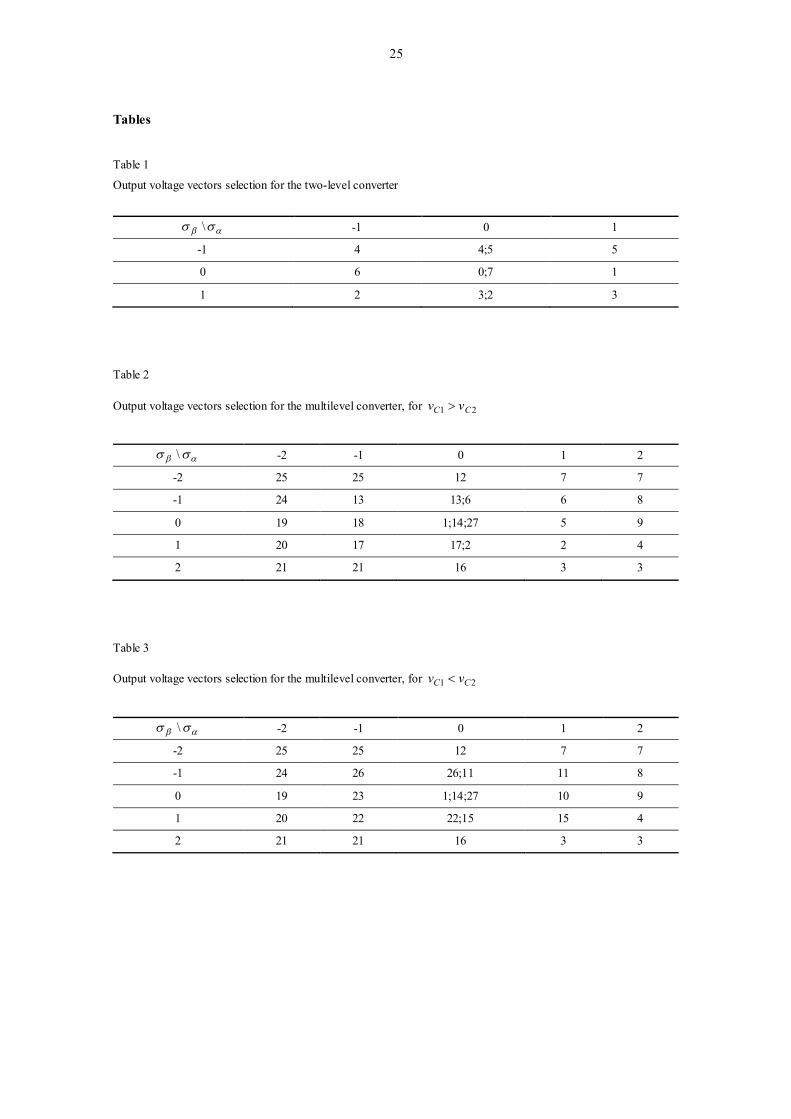
The appropriate vector selection in order to ensure stability for the two-level converter is shown in
Table 1.
"See Table 1 at the end of the manuscript".
For the multilevel converter, the voltage variables and assume values in the set given by:
2,1,0,1,2 (39)
In this control strategy, only when 21 CC vv a new vector is selected. The appropriate vector selection
in order to ensure stability for the multilevel converter is shown in Table 2, for 21 CC vv , and in Table 3,
for 21 CC vv .
"See Table 2 and Table 3 at the end of the manuscript".
The control strategy for the WTG using PI controllers has a block diagram, for example, as
illustrated for the configuration with a two-level converter shown in Fig. 4.
"See Fig. 4 at the end of the manuscript".
The design of PI controllers follows the tuning rules in [37]. Power electronic converters are
modeled as a pure delay [38] and the left-over dynamics are modeled with a second order equivalent
transfer function, following the identification of a step response.

14
The difference between the voltage dcv and the reference voltage *dcv is processed by the PI
controller in order to determine the reference stator currents. The difference between the stator current
and the reference stator current is the error e to be subjected to the output voltage vectors selection for
the two-level converter, Table 1, after being processed by the hysteresis comparator given by (33). The
sliding mode control is a lower level of control as it is normally envisaged with the PI controller.
4. Harmonic assessment
The harmonic behavior computed by the DFT is given by:
1
0
2 )()(N
n
Nnkj nxekX for 1,...,0 Nk (40)
where )(nx is the input signal, a complex number giving the amplitude and phase of the different
sinusoidal components of )(nx .
In order to evaluate the harmonic content of the current injected in the electrical grid, the THD is
considered. The harmonic behavior computed by the THD is given by:
F
HH
X
X 250
2100(%)THD (41)
where HX is the root mean square (RMS) value of the individual harmonic components of the signal,
and FX is the RMS value of the fundamental component.
Standards such as IEEE-519 [39] impose limits for different order harmonics and the THD. The limit
is 5% for THD. Hence, IEEE-519 standard is used in this paper as a guideline for comparison purposes.
5. Simulation results
The mathematical models for the WTG system with the matrix, two-level and multilevel power
converter topologies were implemented in Matlab/Simulink. In this paper it is assumed that 21 for
the fractional-order controller. The WTG system considered has a rated electrical power of 900 kW. The
operational region of the WTG system was simulated for wind speed range from 2.5-25 m/s. Table 4
summarizes the WTG system data.
"See Table 4 at the end of the manuscript".

15
5.1 Case study 1 — Ideal sinusoidal voltage waveforms on the network
The simulation results for a network modeled as a three-phase active symmetrical circuit in series, with
ideal sinusoidal voltage waveforms of 850 V at 50 Hz, were carried out.
The first harmonic and the third harmonic of the current injected into the electrical grid, computed by
the DFT, for the WTG system with the matrix converter is shown in Table 5.
"See Table 5 at the end of the manuscript".
Table 5 shows that the first harmonic never decreases while the third harmonic never increases when
the wind speed increase, due to the respective increase in the rotor speed. Also, it is shown by comparison
of the fractional-order PI controller with the PI controller that the former improves the value for the
first harmonic and consequently reduces the value for the third harmonic. This is an advantage of the PI
controller.
The THD of the output current for the WTG system with the matrix converter is shown in Fig. 5.
"See Fig. 5 at the end of the manuscript".
Fig. 5 shows that the THD with the PI controller is never worst than that with the PI controller,
which is a consequence of what is shown in Table 5.
The first harmonic and the third harmonic of the current injected into the electrical grid, computed by
the DFT, for the WTG system with the two-level converter is shown in Table 6.
"See Table 6 at the end of the manuscript".
A comparison between Table 5 with Table 6 reveals a better performance for the two-level converter,
which is able to achieve enhanced values for the harmonics. Also, it is shown by comparison of the
fractional-order PI controller with the PI controller that the former has advantage.
The THD of the output current for the WTG system with the two-level converter is shown in Fig. 6.
"See Fig. 6 at the end of the manuscript".
Fig. 6 shows that the THD with the PI controller is lesser than that with the PI controller, which is
again a consequence of what is shown in Table 6.
The first harmonic and the third harmonic of the current injected into the electrical grid, computed by
the DFT, for the WTG system with the multilevel converter is shown in Table 7.
"See Table 7 at the end of the manuscript".

16
Comparisons between Table 5, Table 6 and Table 7 reveal a better performance for the multilevel
converter, which is able to achieve the best values for the harmonics. Again it is shown by comparison of
the fractional-order PI controller with the PI controller that the former has advantage.
The THD of the output current for the WTG system with the multilevel converter is shown in Fig. 7.
"See Fig. 7 at the end of the manuscript".
Comparisons between Figure 5, Figure 6 and Figure 7 reveal a better performance for the multilevel
converter, which is able to achieve the smallest values for the THD.
The fractional-order control strategy provides better results comparatively to a classical integer-order
control strategy, in what regards the harmonic performance computed by DFT and THD. The THD of the
output current is lower than 5% limit imposed by IEEE-519 standard [39], for all power converter
topologies considered.
5.2 Case study 2 — Non-ideal sinusoidal voltage waveforms on the network
The simulation results for a network modeled as a three-phase active symmetrical circuit in series, with
850 V at 50 Hz and 5% of third harmonic component, were carried out.
The first harmonic and the third harmonic of the current injected into the electrical grid, computed by
the DFT, for the WTG system with the matrix converter is shown in Table 8. The THD of the output
current for the WTG system with the matrix converter is shown in Fig. 8.
"See Table 8 at the end of the manuscript".
"See Fig. 8 at the end of the manuscript".
The first harmonic and the third harmonic of the current injected into the electrical grid, computed by
the DFT, for the WTG system with the two-level converter is shown in Table 9. The THD of the output
current for the WTG system with the two-level converter is shown in Fig. 9.
"See Table 9 at the end of the manuscript".
"See Fig. 9 at the end of the manuscript".
The first harmonic and the third harmonic of the current injected into the electrical grid, computed by
the DFT, for the WTG system with the multilevel converter is shown in Table 10. The THD of the output
current for the WTG system with the multilevel converter is shown in Fig. 10.
"See Table 10 at the end of the manuscript".
"See Fig. 10 at the end of the manuscript".

17
As in the first case study, the fractional-order control strategy provides better results comparatively to
a classical integer-order control strategy in what regards the harmonic performance and THD. But, the
harmonics are worst than what is reveled in the first case study due to the greater influence of the third
harmonic component.
The presence of the energy-storage elements, in comparison with the matrix converter, and the
increasing number of voltage levels, in comparison with the two-level converter, allows the WTG system
with the multilevel converter to achieve the best harmonic performance. Also, it has been shown that non-
ideal sinusoidal voltage waveforms on the network affect the current THD from the converters.
6. Conclusions
The paper studies a control strategy based on fractional-order controllers for the variable-speed
operation of WTG systems. Comprehensive simulation studies are carried out with three topologies for
the power converters, namely matrix, two-level and multilevel converters. Two case studies are presented,
considering ideal and non-ideal sinusoidal voltage waveforms on the network. For all power converter
topologies considered, the harmonic performance and THD revealed that the power quality injected into
the electrical grid is enhanced using the fractional-order control strategy in comparison with a classical
integer-order control strategy. Also, the comparative study illustrates that the best harmonic performance
is achieved using a WTG system with the multilevel converter.
References
[1] Saheb-Koussa D, Haddadi M, Belhamel M, Hadji S, Nouredine S. Modeling and simulation of the fixed-speed
WECS (wind energy conversion system): Application to the Algerian Sahara area. Energy 2010;35(10):4116–
25.
[2] Fusco F, Nolan G, Ringwood JV. Variability reduction through optimal combination of wind/wave resources –
An Irish case study. Energy 2010;35(1):314–25.
[3] Ullah NR, Thiringer T. Variable speed wind turbines for power system stability enhancement. IEEE Trans
Energy Convers 2007;22(1):52–60.
[4] Carrasco JM, Franquelo LG, Bialasiewicz JT, Galvan E, Guisado RCP, Prats AM, Leon JI, Moreno-Alfonso N.
Power-electronic systems for the grid integration of renewable energy sources: A survey. IEEE Trans Ind
Electron 2006;53(4):1002–16.
[5] Blaabjerg F, Chen Z, Kjaer SB. Power electronics as efficient interface in dispersed power generation systems.
IEEE Trans. Power Electron 2004;19(5):1184–94.
[6] Lin W-M, Hong C-M, Cheng F-S. Fuzzy neural network output maximization control for sensorless wind
energy conversion system. Energy 2010;35(2):592–601.

18
[7] Lin W-M, Hong C-M. Intelligent approach to maximum power point tracking control strategy for variable-
speed wind turbine generation system. Energy 2010;35(6): 2440–7
[8] Lin W-M, Hong C-M, Cheng F-S. On-line designed hybrid controller with adaptive observer for variable-speed
wind generation system. Energy 2010;35(7): 3022–30.
[9] Baroudi JA, Dinavahi V, Knight AM. A review of power converter topologies for wind generators. Renew.
Energy 2007;32(14):2369–85.
[10] Camblong H, Tapia G, Rodríguez M. Robust digital control of a wind turbine for rated-speed and variable-
power operation regime. IEE Proc.-Control Theory Appl. 2006;153(1):81–91.
[11] Fernandez LM, Garcia CA, Jurado F. Comparative study on the performance of control systems for doubly fed
induction generator (DFIG) wind turbines operating with power regulation. Energy 2008;33(9):1438–52.
[12] Hansen AD, Michalke G. Modelling and control of variable-speed multi-pole permanent magnet synchronous
generator wind turbine. Wind Energy 2008;11(5):537–54.
[13] Li H, Chen Z. Design optimization and site matching of direct-drive permanent magnet wind power generator
systems. Renew. Energy 2009;34(4):1175–84.
[14] Slootweg JG, de Haan SWH, Polinder H, Kling WL. General model for representing variable speed wind
turbines in power system dynamics simulations. IEEE Trans. Power Syst 2003;18(1):144–51.
[15] Slootweg JG, de Haan SWH, Polinder H, Kling WL. Aggregated modelling of wind parks with variable speed
wind turbines in power system dynamics simulations. In: Proc. 14th Power Systems Computation Conf.,
Sevilla, Spain, 2002.
[16] Poller MA. Doubly-fed induction machine models for stability assessment of wind farms. In: Proc. IEEE
Bologna Power Tech Conf., Bologna, Italy, 2003.
[17] Ong C-M. Dynamic Simulation of Electric Machinery: Using Matlab/Simulink. Prentice-Hall, New Jersey,
1998, pp. 259–350.
[18] Senjyu T, Tamaki S, Urasaki N, Uezato K. Wind velocity and position sensorless operation for PMSG wind
generator. In: Proc. 5th Int. Conf. on Power Electronics and Drive Systems, Singapore, 2003, 787–92.
[19] Cárdenas R, Peña R, Wheeler P, Clare J, Asher G. Control of the reactive power supplied by a WECS based on
an induction generator fed by a matrix converter. IEEE Trans. Ind. Electron 2009;56(2):429–38.
[20] Melício R, Mendes VMF, Catalão JPS. Fractional-order control and simulation of wind energy systems with
PMSG/full-power converter topology. Energy Conv. Manag. 2010;51(6):1250 –8.
[21] Pinto S, Silva J. Sliding mode direct control of matrix converters. IET Electr Power Appl 2007;1(3):439–48.
[22] Cardenas R, Pena R, Wheeler P, Clare J. Reactive power capability of WECS based on matrix converter.
Electron. Letter 2008;44(11):674–6.
[23] Jia S, Wang X, Tseng KJ. Matrix converters for wind energy systems. In: Proc. 2nd IEEE Conf. Ind. Electron.
Appl., Harbin, China, 2007, pp. 488–94.
[24] Melício R, Mendes VMF, Catalão JPS. A pitch control malfunction analysis for wind turbines with permanent
magnet synchronous generator and full-power converters: proportional integral versus fractional-order
controllers. Electr. Power Compon. Syst. 2010;38(4):387–406.
[25] Silva JF, Pinto SF. In: M.H. Rashid (Ed.), Control Methods for Switching Power Converters, Power
Electronics Handbook, New York, 2007, pp. 935–998.
[26] Babaei E, Hosseini SH, Gharehpetian GB, Haque MT, Sabahi M. Reduction of dc voltage sources and switches
in asymmetrical multilevel converters using a novel topology. Electr. Power Syst. Res. 2007;77(8):1073–85.
[27] Melício R, Mendes VMF, Catalão JPS. Power converter topologies for wind energy conversion systems:
integrated modeling, control strategy and performance simulation. Renew. Energy 2010;35(10):2165–74.

19
[28] Barros JD, Silva JF. Optimal predictive control of three-phase NPC multilevel converter for power quality
applications. IEEE Trans. Ind. Electron 2008;55(10):3670–81.
[29] Alepuz S, Busquets-Monge S, Bordonau J, Gago J, Gonzalez D, Balcells J. Interfacing renewable energy
sources to the utility grid using a three-level inverter. IEEE Trans. Ind. Electron. 2006;53(5):1504–11.
[30] Portillo RC, Prats MM, León JI, Sanchez JA, Carrasco JM, Galván E, Franquelo LG. Modeling strategy for
back-to-back three-level converters applied to high-power wind turbines. IEEE Trans. Ind. Electron.
2006;53(5):1483–91.
[31] Podlubny I. Fractional-order systems and PI-lambda-D-mu-controllers. IEEE Trans Autom Control
1999;44(1):208–14.
[32] Li W, Hori Y. Vibration suppression using single neuron-based PI fuzzy controller and fractional-order
disturbance observer. IEEE Trans. Ind. Electron 2007;54(1):117–26.
[33] Cao JY, Cao BG. Design of fractional order controllers based on particle swarm optimization. In Proc. 1st
IEEE Conference on Industrial Electronics and Applications, Singapore, May 2006.
[34] Calderón AJ, Vinagre BM, Feliu V. Fractional order control strategies for power electronic buck converters.
Signal Process 2006;86(10):2803–19.
[35] Biswas A, Das S, Abraham A, Dasgupta S. Design of fractional-order (PID mu)-D-lambda controllers with an
improved differential evolution. Eng. Appl. Artif. Intell 2009; 22:343–50.
[36] Beltran B, Ahmed-Ali T, Benbouzid MEH. Sliding mode power control of variable-speed wind energy
conversion system. IEEE Trans Energy Convers. 2008;23(2):551–8.
[37] Maione G, Lino P. New tuning rules for fractional PI-alfa controllers. Nonlinear Dynamics 2007; 49(1-2):251–
7.
[38] Chinchilla M, Arnaltes S, Burgos JC. Control of permanent-magnet generators applied to variable-speed wind
energy systems connected to the grid. IEEE Trans. Energy Convers. 2006;21(1):130–5.
[39] IEEE Guide for Harmonic Control and Reactive Compensation of Static Power Converters, IEEE Standard
519-1992.

20
Figure captions
Fig. 1. WTG system with matrix converter.
Fig. 2. WTG system with two-level converter.

21
Fig. 3. WTG system with multilevel converter.
Fig. 4. Diagram of a WTG with two-level converter employing fractional-order controllers.

22
Fig. 5. THD of the current injected into the electrical grid for the matrix converter — Case study 1.
Fig. 6. THD of the current injected into the electrical grid for the two-level converter — Case study 1.

23
Fig. 7. THD of the current injected into the electrical grid for the multilevel converter — Case study 1.
Fig. 8. THD of the current injected into the electrical grid for the matrix converter — Case study 2.

24
Fig. 9. THD of the current injected into the electrical grid for the two-level converter — Case study 2.
Fig. 10. THD of the current injected into the electrical grid for the multilevel converter — Case study 2.
25
Tables
Table 1
Output voltage vectors selection for the two-level converter
\ -1 0 1
-1 4 4;5 5
0 6 0;7 1
1 2 3;2 3
Table 2
Output voltage vectors selection for the multilevel converter, for 21 CC vv
\ -2 -1 0 1 2
-2 25 25 12 7 7
-1 24 13 13;6 6 8
0 19 18 1;14;27 5 9
1 20 17 17;2 2 4
2 21 21 16 3 3
Table 3
Output voltage vectors selection for the multilevel converter, for 21 CC vv
\ -2 -1 0 1 2
-2 25 25 12 7 7
-1 24 26 26;11 11 8
0 19 23 1;14;27 10 9
1 20 22 22;15 15 4
2 21 21 16 3 3

26
Table 4
WTG system data
Turbine moment of inertia 250010³ kgm²
Turbine rotor diameter 49 m Hub height 45 m Tip speed 17.64-81.04 m/s
Rotor speed 6.9-31.6 rpm Generator rated power 900 kW
Generator moment of inertia 10010³ kgm²
Table 5
First harmonic and third harmonic of the current injected into the electrical grid for the matrix converter — Case study 1
Wind speed PI controller PI controller (m/s) First harmonic (%) Third harmonic (%) First harmonic (%) Third harmonic (%)
2.5 87.92 1.89 87.22 2.10 5.0 88.10 1.78 87.90 1.91
7.5 88.15 1.59 88.04 1.64
10.0 88.41 1.30 88.11 1.46 12.5 88.50 1.24 88.30 1.37
15.0 88.63 1.16 88.42 1.21 17.5 88.80 1.11 88.50 1.18
20.0 88.80 1.11 88.50 1.18
22.5 88.80 1.11 88.50 1.18 25.0 88.80 1.11 88.50 1.18
Table 6
First harmonic and third harmonic of the current injected into the electrical grid for the two-level converter — Case study 1
Wind speed PI controller PI controller
(m/s) First harmonic (%) Third harmonic (%) First harmonic (%) Third harmonic (%)
2.5 93.20 1.61 92.83 1.78
5.0 93.80 0.97 93.10 1.42
7.5 94.20 0.89 93.30 0.94 10.0 94.30 0.27 93.40 0.30
12.5 94.30 0.27 93.50 0.30 15.0 94.30 0.27 93.50 0.30
17.5 94.40 0.27 93.50 0.30
20.0 94.40 0.27 93.50 0.30 22.5 94.40 0.27 93.50 0.30
25.0 94.40 0.27 93.50 0.30

27
Table 7
First harmonic and third harmonic of the current injected into the electrical grid for the multilevel converter — Case study 1
Wind speed PI controller PI controller (m/s) First harmonic (%) Third harmonic (%) First harmonic (%) Third harmonic (%)
2.5 93.90 1.57 93.35 1.60
5.0 94.07 1.42 94.00 1.48 7.5 94.19 0.83 94.06 0.88
10.0 94.38 0.33 94.14 0.47 12.5 94.78 0.27 94.28 0.30
15.0 94.94 0.23 94.45 0.26
17.5 95.18 0.23 94.63 0.26 20.0 95.18 0.23 94.82 0.26
22.5 95.20 0.23 94.82 0.26
25.0 95.24 0.23 94.82 0.26
Table 8
First harmonic and third harmonic of the current injected into the electrical grid for the matrix converter — Case study 2
Wind speed PI controller PI controller (m/s) First harmonic (%) Third harmonic (%) First harmonic (%) Third harmonic (%)
2.5 86.67 4.99 86.30 5.10 5.0 87.59 4.94 87.67 5.02
7.5 87.99 4.82 87.84 4.95
10.0 88.04 4.77 87.84 4.95 12.5 88.16 4.71 87.84 4.95
15.0 88.16 4.71 88.05 4.91 17.5 88.23 4.68 88.11 4.89
20.0 88.23 4.68 88.11 4.89
22.5 88.23 4.68 88.11 4.89 25.0 88.23 4.68 88.11 4.89

28
Table 9
First harmonic and third harmonic of the current injected into the electrical grid for the two-level converter — Case study 2
Wind speed PI controller PI controller (m/s) First harmonic (%) Third harmonic (%) First harmonic (%) Third harmonic (%)
2.5 90.58 4.80 89.67 4.50
5.0 90.97 4.59 90.67 4.68 7.5 91.09 3.42 90.92 3.49
10.0 91.17 3.42 91.03 3.49 12.5 91.15 3.42 91.03 3.49
15.0 91.14 3.43 91.03 3.51
17.5 91.10 3.43 90.96 3.51 20.0 91.10 3.43 90.96 3.51
22.5 91.10 3.43 90.96 3.51
25.0 91.10 3.43 90.96 3.51
Table 10
First harmonic and third harmonic of the current injected into the electrical grid for the multilevel converter — Case study 2
Wind speed PI controller PI controller (m/s) First harmonic (%) Third harmonic (%) First harmonic (%) Third harmonic (%)
2.5 87.90 4.94 87.62 4.99 5.0 88.00 4.92 87.77 4.95
7.5 93.80 2.44 93.51 2.91
10.0 93.90 2.11 93.72 2.34 12.5 94.11 2.10 93.90 2.33
15.0 94.65 2.10 94.10 2.33 17.5 94.77 2.10 94.26 2.33
20.0 94.93 2.10 94.45 2.33
22.5 95.02 2.10 94.76 2.33 25.0 95.02 2.10 94.76 2.33