comparative study on magnetic circuit … · vol. 11, no. 10, may 2016 issn 1819-6608 arpn journal...
TRANSCRIPT
VOL. 11, NO. 10, MAY 2016 ISSN 1819-6608
ARPN Journal of Engineering and Applied Sciences
©2006-2016 Asian Research Publishing Network (ARPN). All rights reserved.
www.arpnjournals.com
6703
COMPARATIVE STUDY ON MAGNETIC CIRCUIT ANALYSIS BETWEEN INDEPENDENT COIL EXCITATION AND CONVENTIONAL THREE
PHASE PERMANENT MAGNET MOTOR
A. Nazifah Abdullah1, M. Norhisam2, S. Khodijah1, N. Amaniza1, and N. Nadiah Ayop1 1School of Electrical System Engineering University Malaysia Perlis, Electrical Machines and Drives Research Group, Perlis, Malaysia
2Department of Electrical & Electronic, University Putra Malaysia, Serdang, Selangor, Malaysia E-Mail: [email protected]
ABSTRACT
Coil arrangement is one of essential part in electrical machine design that affects the torque performance of the machine. Thus, a new stator slot structure of permanent magnet machine called Independent Coil Excitation Permanent Magnet Motor (ICE-PMM) is introduced. Design and magnetic circuit analysis of ICE-PMM is presented. In addition, qualitative comparisons are made with the other conventional types of Permanent Magnet Machines (PMM) which are Slot-type and Slotless rotor. A brief description on the basic concept of the ICE-PMM motor design along with the Slot-type and Slotless rotor structure are presented. The main objective of this paper is to evaluate PMM type that has better static torque with low cogging between conventional and ICE-PMM. Simulation studies of all three PMM are presented in order to evaluate the feature of its flux distribution, flux linkage, flux flow, cogging and static torque characteristics. In a conclusion, the ICE-PMM could perform better as high static torque PMM with lower cogging compare to the other two conventional types. Keywords: permanent magnet motor, independent coil excitation motor, slotless, cogging torque, static torque, magnetic circuit analysis, Finite Element Method. INTRODUCTION
The rise rate of depletion of fossil energy resources caused growing on energy demand and cost. In contrast, the recent focus is on extensive research activities in the field of high efficiency and high technology of electric motors and drive. By replacing DC and AC induction machines with permanent magnet machines (PMM) has recently increased advances in aerospace, medical equipment, military and automotive industries. In addition, with the advent of NdFeB permanent magnet (PM) material in the industry as high quality, high coercivity, high energy product and high temperature grade up to 180°C, PM enables PMM to rank as the high power density and high efficiency electrical machine. The structure and unique operation mode of PMM motor provide advantage in speed and position control [1].
Nowadays PMM gaining wide popularity because of variety of factors including its simple and rugged structure which no brushes and slip rings excitation. Typically, the essential design of PMM for implementation of the magnetic circuit analysis is both on the structure of stator and rotor parts [2]. The main objective of this project is to perform a comparative study on magnetic circuit analysis of three phases PMM between Independent Coil Excitation Permanent Magnet Motor (ICE-PMM) as currently approach of coil arrangement and two types of rotor for conservative PMM which are Slot-Type Rotor and Slotless Rotor type. BASIC PRINCIPLE OF ICE-PMM
The basic principle of this ICE-PMM is the positioning of stator teeth with the pitch arrangement of the motor. The position of the stator teeth is arranged
based on the pitch, ד angle at the rotor which consists of rotor slot and permanent magnet as illustrated in Figures-1 and -2. Both figures show the basic concept of stator teeth arrangement of ICE-PMM for linear and rotational motor respectively. The value of pitch, ד angle of ICE-PMM was determined due to the number of PM poles which has 18 poles. Means the pitch pole for ICE-PMM is 9 pitches and represented as 40º each.
Figure-1. Stator teeth positioning for linear pitch arrangement [3].
Figure-2. Stator teeth positioning for rotational pitch arrangement [3].
The movement of the motor is basically
principled by the magnetic interaction between the rotor

VOL. 11, NO. 10, MAY 2016 ISSN 1819-6608
ARPN Journal of Engineering and Applied Sciences
©2006-2016 Asian Research Publishing Network (ARPN). All rights reserved.
www.arpnjournals.com
6704
and stator. So, the information of magnetic polarity of the rotor slot is essential in order to create the variable magnetic polarity at the stator by using the concept of right hand rule. The magnetic polarity of the stator teeth is determined by the direction of the flowing current in winding coils.
Figure-3 shows the polarity of the switching sequence as known as commutator sequence for the three phases when the rotor needs to be moved forward direction. Figure-3(a) shown that for coil A at first step pulse which is at 0° of the pitch, the voltage is in positive signal resulting in the repulsion of the stator teeth A to the nearest S pole and attraction to the nearest N pole at the rotor slot. This repulsion makes the rotor to move in forward direction. Same instance repeats for the voltage signal at coil C to produce movement in the same direction. At least only two of the three phases are active in generating voltage at a time for 120 degrees conduction. As can be seen, no signal is being supplied to the coil B because of the position of stator teeth and rotor slot is aligned to each other. In this condition, the repulsion and attraction between rotor and stator are not necessary.
When the stator teeth is positioned at second step pulse, pitch 7° as shown in Figure-3(b), the pattern of signal supplied to coil A, B and C is changed due to the changing of the rotor position. The same pattern of the voltage signal is applied to keep the rotor incessantly rotating at the same direction as shown in Figures-3(c), 3(d), 3(e) and 3(f) [4].
Figure-3. Principle of the rotor movement [4].
STRUCTURAL FEATURES OF ICE-PMM AND CONVENTIONAL PMM
Basically permanent magnet motor (PMM) consist four basic components which are stator, rotor, permanent magnets and coils. In this research, the stator and rotor are made up of laminated silicon steel and ferritic stainless steel respectively. The PMM material is made from Neodymium Iron Boron (NdFeB) which from high quality raw material to has lastingness and high remanence. Maximum high flux density that could be produced by NdFEB is about 0.6T to 1.6T.
Initially, ICE-PMM dimensions are illustrated as shown in Figure-4 and Table-1. The motor is fixed with diameter 200 mm, thickness 30 mm, air gap 0.5 mm and coil magneto static force per phase 4750 AT. In order to ensure the flux is flows toward the stator teeth and back to rotor slot, the polarity of permanent magnets that inserted in the rotor are arranged back to back.
Figure-4. Cross section of the ICE-PMM [4].
Table-1. Dimension of the ICE-PMM.
VOL. 11, NO. 10, MAY 2016 ISSN 1819-6608
ARPN Journal of Engineering and Applied Sciences
©2006-2016 Asian Research Publishing Network (ARPN). All rights reserved.
www.arpnjournals.com
6705
The basic structure of ICE-PMM is presented in Figure-5. The stator and rotor are made up of eighteen coils and permanent magnet poles respectively. These coils are displaced by 120° electrical degrees to each phase arranged by group based on its phase which. Therefore, instead setting up the excitation electronically, the coils are arranged mechanically so that it computes with correct excitation angle. The starting angle for each phase are according to the motor half pitch, σ which is 20° as shown in Figure-5. Each coil phase has to be arranged by (1/3)rd or 6.67° of the motor half pitch. This means that the slot for Phase A coil is situated at the zero half pitch, the coil Phase B is situated at (1/3)rd of the motor half pitch and coil phase C is situated at (2/3)rd of the motor half pitch. The angle difference between first stator teeth Phase A and last stator teeth Phase C is 2σ/3 same as to the first stator teeth Phase C and last stator teeth Phase B. The configuration of the ICE-PMM is similar to the electrical degree and thus it is shifted for each energized phase by 120° mechanical degrees [4].
As stated earlier, conventional PMM is analyzed for two types of rotor which are slot-type and slotless rotor. The main difference between slot-type and slotless PMM are its rotor slot structure and material. For slot-type PMM, its rotor slot is made from magnetic material. On the contrary with slotless PMM, it clearly designed with no slot. Therefore, the permanent magnet must be held by a holder which made of non-magnetic material. Figures-6 and -7 show the tructure of slot-type PMM and slotless PMM respectively in exploded view.
Figure-5. Structural features of the ICE-PMM[4].
Whereas, for conventional PMM, the main different compare to ICE-PMM is obviously on its stator structure as the coil arrangement for ICE-PMM is a novelty. In addition, for distributed windings, the ratio slot per pole per phase should be in the range of 0.25 – 0.5 in other to minimize the cogging torque [2]. Hence, the number of rotor poles and stator slots are resulted to be twenty and eighteen respectively. So for one pitch of conventional PMM is equal to 36°, in contrast to ICE-PMM which has 40°. The basic dimensions of conventional PMM that differ with ICE-PMM are also shown in Table-2 below.
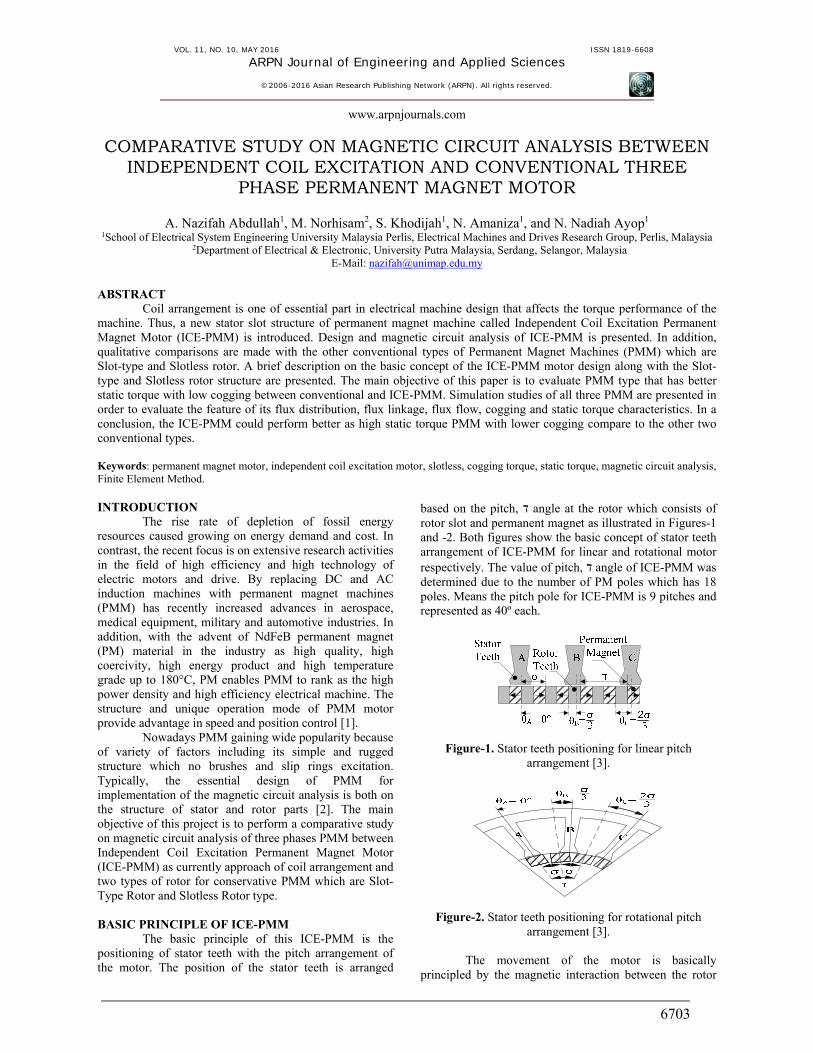
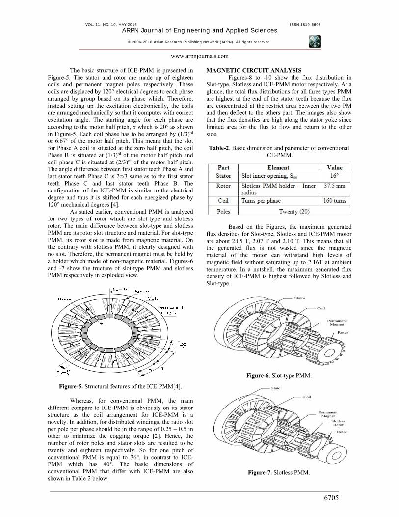
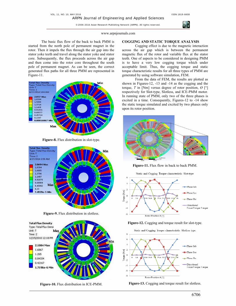
MAGNETIC CIRCUIT ANALYSIS Figures-8 to -10 show the flux distribution in
Slot-type, Slotless and ICE-PMM motor respectively. At a glance, the total flux distributions for all three types PMM are highest at the end of the stator teeth because the flux are concentrated at the restrict area between the two PM and then deflect to the others part. The images also show that the flux densities are high along the stator yoke since limited area for the flux to flow and return to the other side. Table-2. Basic dimension and parameter of conventional
ICE-PMM.
Based on the Figures, the maximum generated flux densities for Slot-type, Slotless and ICE-PMM motor are about 2.05 T, 2.07 T and 2.10 T. This means that all the generated flux is not wasted since the magnetic material of the motor can withstand high levels of magnetic field without saturating up to 2.16T at ambient temperature. In a nutshell, the maximum generated flux density of ICE-PMM is highest followed by Slotless and Slot-type.
Figure-6. Slot-type PMM.
Figure-7. Slotless PMM.
VOL. 11, NO. 10, MAY 2016 ISSN 1819-6608
ARPN Journal of Engineering and Applied Sciences
©2006-2016 Asian Research Publishing Network (ARPN). All rights reserved.
www.arpnjournals.com
6706
The basic flux flow of the back to back PMM is started from the north pole of permanent magnet in the rotor. Then it impels the flux through the air gap into the stator yoke teeth and travel along the stator yoke and stator core. Subsequently, the flux proceeds across the air gap and then come into the rotor core throughout the south pole of permanent magnet. As can be seen, the correct generated flux paths for all three PMM are represented in Figure-11.
Figure-8. Flux distribution in slot-type.
Figure-9. Flux distribution in slotless.
Figure-10. Flux distribution in ICE-PMM.
COGGING AND STATIC TORQUE ANALYSIS Cogging effect is due to the magnetic interaction
across the air gap which is between the permanent magnetic flux of the rotor and variable flux at the stator teeth. One of aspects to be considered in designing PMM is to have a very low cogging torque which under acceptable limit. Thus, the cogging torque and static torque characteristic results for all three types of PMM are generated by using software simulation, FEM.
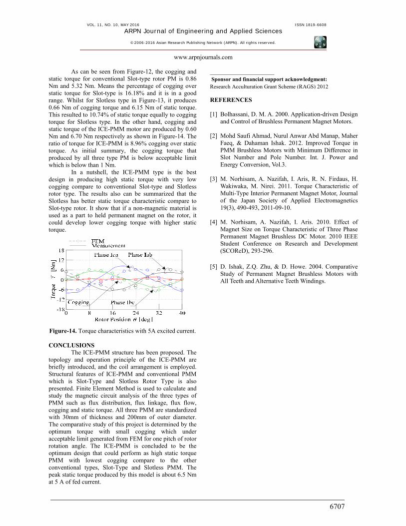
From the data of FEM, the results are plotted as shown in Figures-12, -13 and -14 as the cogging and the torque, T in [Nm] versus degree of rotor position, Ɵ [°] respectively for Slot-type, Slotless, and ICE-PMM motor. In running state of PMM, only two of the three phases is excited in a time. Consequently, Figures-12 to -14 show the static torque simulated and excited by two phases only upon its rotor position.
Figure-11. Flux flow in back to back PMM.
Figure-12. Cogging and torque result for slot-type.
Figure-13. Cogging and torque result for slotless.
VOL. 11, NO. 10, MAY 2016 ISSN 1819-6608
ARPN Journal of Engineering and Applied Sciences
©2006-2016 Asian Research Publishing Network (ARPN). All rights reserved.
www.arpnjournals.com
6707
As can be seen from Figure-12, the cogging and static torque for conventional Slot-type rotor PM is 0.86 Nm and 5.32 Nm. Means the percentage of cogging over static torque for Slot-type is 16.18% and it is in a good range. Whilst for Slotless type in Figure-13, it produces 0.66 Nm of cogging torque and 6.15 Nm of static torque. This resulted to 10.74% of static torque equally to cogging torque for Slotless type. In the other hand, cogging and static torque of the ICE-PMM motor are produced by 0.60 Nm and 6.70 Nm respectively as shown in Figure-14. The ratio of torque for ICE-PMM is 8.96% cogging over static torque. As initial summary, the cogging torque that produced by all three type PM is below acceptable limit which is below than 1 Nm.
In a nutshell, the ICE-PMM type is the best design in producing high static torque with very low cogging compare to conventional Slot-type and Slotless rotor type. The results also can be summarized that the Slotless has better static torque characteristic compare to Slot-type rotor. It show that if a non-magnetic material is used as a part to held permanent magnet on the rotor, it could develop lower cogging torque with higher static torque.
Figure-14. Torque characteristics with 5A excited current. CONCLUSIONS
The ICE-PMM structure has been proposed. The topology and operation principle of the ICE-PMM are briefly introduced, and the coil arrangement is employed. Structural features of ICE-PMM and conventional PMM which is Slot-Type and Slotless Rotor Type is also presented. Finite Element Method is used to calculate and study the magnetic circuit analysis of the three types of PMM such as flux distribution, flux linkage, flux flow, cogging and static torque. All three PMM are standardized with 30mm of thickness and 200mm of outer diameter. The comparative study of this project is determined by the optimum torque with small cogging which under acceptable limit generated from FEM for one pitch of rotor rotation angle. The ICE-PMM is concluded to be the optimum design that could perform as high static torque PMM with lowest cogging compare to the other conventional types, Slot-Type and Slotless PMM. The peak static torque produced by this model is about 6.5 Nm at 5 A of fed current.
_______________________ Sponsor and financial support acknowledgment: Research Acculturation Grant Scheme (RAGS) 2012 REFERENCES [1] Bolhassani, D. M. A. 2000. Application-driven Design
and Control of Brushless Permanent Magnet Motors.
[2] Mohd Saufi Ahmad, Nurul Anwar Abd Manap, Maher Faeq, & Dahaman Ishak. 2012. Improved Torque in PMM Brushless Motors with Minimum Difference in Slot Number and Pole Number. Int. J. Power and Energy Conversion, Vol.3.
[3] M. Norhisam, A. Nazifah, I. Aris, R. N. Firdaus, H. Wakiwaka, M. Nirei. 2011. Torque Characteristic of Multi-Type Interior Permanent Magnet Motor, Journal of the Japan Society of Applied Electromagnetics 19(3), 490-493, 2011-09-10.
[4] M. Norhisam, A. Nazifah, I. Aris. 2010. Effect of Magnet Size on Torque Characteristic of Three Phase Permanent Magnet Brushless DC Motor. 2010 IEEE Student Conference on Research and Development (SCOReD), 293-296.
[5] D. Ishak, Z.Q. Zhu, & D. Howe. 2004. Comparative
Study of Permanent Magnet Brushless Motors with All Teeth and Alternative Teeth Windings.