comparativeefficiencyandultimate strength of and - saimm · 300 shotcrete test panel 300 jack for...
TRANSCRIPT

~J. S. Atr. Inst. Min. Metal/., vol. 92, no. 11/12.Nov.jDec. 1992. pp. 303-323.
Comparative efficiency and ultimate strength of mesh- andfibre-reinforced shotcrete as determined from full-scalebending tests
by H.A.D. Kirsten*
SYNOPSISThe structural competence of mesh- and fibre-reinforced shotcrete was investigated in two series of tests on full-scale panels. It was found that uniformly distributed loading was marginally less demanding than point loading, meshreinforcement was superior to fibre reinforcement, Dramix fibre and Melt Extract fibre were similar in reinforcingcharacteristics, and 30 mm to 35 mm was an optimum fibre length. Furthermore, the consistency of the fibrecontent could not be assured on practical mining sites, and an average fibre content of about 1,5 per cent was themaximum that could be obtained for fibre lengths not exceeding 35 mm. Also, owing to its greater flexibility,shotcrete reinforced with diamond mesh was preferable to fibre-reinforced shotcrete in mining excavations subject tosqueezing conditions. In view of the difficulties associated with assuring the consistency of the fibre content in miningapplications, it appears that the sophisticated attributes of fibre-reinforced shotcrete can be effectively exploited onlyin civil-engineering applications in which quality assurance is subject to explicit contractual control.Load-deflection curves, together with measurements of compressive stresses in the surfaces of some of the panels,enabled the ultimate flexural strength of reinforced shotcrete to be rigorously formulated, and rigorous designprocedures for shotcrete subject to bending and direct thrust to be developed. The application of the procedures isdemonstrated in a practical design case in which the moments and thrusts in a tunnel lining are determined in anumerical analysis of the interaction between the lining, the surrounding rock, and the rock-reinforcing system.
SAMEVATTINGDie strukturele geskiktheid van maas-en veselgewapende spuitbeton is in twee reekse toetse op volskaalse pane leondersoek. Daar is gevind dat egalig verspreide belasting marginaal minder veeleisend was as puntbelasting, datmaaswapening beter as veselwapening was, dat Dramix-vesel en Melt Extract-vesel soortgelyke wapeningeienskappegehad het, en dat 30 mm tot 35 mm 'n optimale vesellengte was. Verder kan daar nie 'n egalige veselinhoud in diepraktyk op mynboupersele verseker word nie, en 'n gemiddelde veselinhoud van ongeveer 1,5 persent was diemaksimum wat vir vesellengtes van hoogstens 35 mm verkry kon word. Omdat dit meer buigsaam is, was spuitbetonwat met ruitmaasdraad gewapen is, verkieslik bo veselgewapende spuitbeton in mynuitgrawings wat aandruktoestande onderworpe is. In die lig van die probleme om 'n egalige veselinhoud in mynbouaanwendings teverseker, wil dit voorkom asof die gesofistikeerde eienskappe van veselgewapende spuitbeton slegs in siviele-ingenieursaanwendings, waar gehalteversekering aan uitdrukke kontraktuele beheer onderworpe is, doeltreffendbenut kan word.Lasdefleksiekrommes, tesame met die meting van drukspannings in die oppervlakke van sommige van die panele,het dit moontlik gemaak om die breekbuigsterkte van gewapende spuitbeton streng te formuleer en nougesetteontwerpprosedures te ontwikkel vir spuitbeton wat aan buiging en regstreekse stootkrag onderworpe is. Dietoe passing van die prosedures word gedemonstreer in 'n praktiese ontwerpgeval waarin die momente enstootkragte in 'n tonnelvoering bepaal word in 'n numeriese ontleding van die- wisselwerking tussen die voering, dieomringende rots, en die rotsversterkingstelsel.
INTRODUCTION
Kirsten and Labrum1, in a first series of panel tests,showed that shotcrete reinforced with 30 mm long Dramixfibre competently sustained load at large deflection, andthat it was on average 20 per cent less effective in terms ofthickness, and 44 per cent less effective in terms of load,than shotcrete reinforced with diamond mesh at a fibrecontent of 1,43 per cent by weight. The superiority of meshover fibre reinforcement was ascribed to the low contentand relatively limited length of the fibre used. The meshreinforcement was located in the middle of the test panelsand, as such, was more efficient than the fibre'reinforcement, of which only a small fraction of the totalcontent was available in the tension sides of the panelstested. An increase in fibre content to 3 per cent by weight
Steffen, Robertson & Kirsten Inc., P.O. Box 55291, Northlands,2116 Transvaal.
@ The South African Institute of Mining and Metallurgy, 1992. SAISSN 0038-223Xj3.00 + 0.00. Paper received October 1991;revised paper received July 1992.
was expected to improve the load-carrying capacity andeffective thickness of the shotcrete. The second series oftests, which is described in the present paper, was carriedout to confirm this assessment.
An extensive literature review by Kirsten and Labrum1showed that only five series of large-scale panel tests hadbeen conducted world-wide. The number of tests in eachseries was limited, and the tests were largely unrelated tomining conditions. Only two of the test series examinedbending deflections of the magnitudes found in mines. Innone of the tests was the effect of thickness investigated.The spacing of the supports was about 2,5 m compared withthe 1 m grid generally used in mines. Point or punch loadswere simulated in the test series reviewed. It is unlikely forthe rock behind every section of shot crete betweenadjoining bolts or anchors to present itself in every case as asharp object or as a rigid, relatively free block fittingaccurately between the adjoining bolts or anchors. In thenatural situation, the load on shotcrete is more likely to bedistributed uniformly. All the shortcomings in the tests
Journal of The South African Institute of Mining and Metallurgy NOVEMBER/DECEMBER. 1992 303

1838
1000. . .DGE OF TEST PANEL
0'1U1C)
~ANCHORPLATE .r------___.,0
11I II---VETTER BAG I II I II I II II II II II I
0L______--_.J
0.
A...
. . .FigureI-Plan of the panel-testing frame
Journal of The South African Institute of Mining and Metallurgy
pressurized bag with a lifting height of 520 mm. Hydraulicpressurization of the bag limited the energy in the loadingsystem, and ensured that panel deflections could be trackedin a controlled manner beyond peak loading. A point loadcould also be applied to the centre of the panel by means ofa hand-operated hydraulic jack with a stroke length of 150mm. A bearing plate, 100 mm square, was placed betweenthe jack and the panel. The centre of the panel could bedeflected to a maximum of 150 mm for either of theloading cases.
The pressure in the bag was measured by means of apressure transducer, and the load in the jack by means of aload cell, the output signals from both devices beingrecorded as analogue voltages. The deflections of the panelwere recorded at three positions: one at each of twodiametrically opposite bolt positions, and one at the centreof the panel. Linear variable differential transducers with atravel of about 25 mm and an analogue voltage output wereused for this purpose.
The strains in the surface of the shotcrete were measuredon the compression sides of some of the panels at one ofthe bolts and at midspan; 75 mm long electrical resistancestrain gauges were used for this purpose, from which theoutput signals were recorded as analogue voltages. Thestrains were measured in two directions at each of thesepositions: parallel to, and at 45 degrees to, the sides of thepanel. The output signals from the various devices were fed
published constituted further justification for the additionalfull-size panel tests reported here.
The mechanics of the composite action between theshotcrete and the reinforcement, mesh or fibre, has not beenresolved definitively. The measurement of surface strains atselect positions on some of the panels was thereforeundertaken as an additional objective in the second testseries to assist in the development of a rigorous formulationof the ultimate flexural strength of reinforced shotcrete.--------
EQUIPMENT USED IN THE PANEL TEST------- -----
The interaction between shotcrete and rock in a realtunnel is complex and cannot be modelled accurately in alaboratory test. However, the following was considered tobe representative of the actual situation: a continuousshotcrete panel of which the central square-metre section issecured by means of four regularly spaced bolts andsubjected to uniformly distributed or point loads in bending.
A steel frame was accordingly manufactured as shown inFigures 1 and 2. The frame took a 1,6 m square panel andprovided for bolt supports at the corners of the central1,0 m square section. Bearing plates, 100 mm square, wereplaced under the bolt heads to simulate actual conditions. Thearrangement ensured continuity across the lines of supportbetween the bolts that was similar to actual conditions.
The frame further allowed a uniformly distributed load tobe applied to the panel by means of a hydraulically
H.D.BOLT .
"AOCKBOLTS"
BASE PLATE
...A
.
304 NOVEMBER/DECEMBER 1992

300
SHOTCRETE TEST PANEL
300
JACK FOR CENTREPOINT LOADING
EXISTING HOLDINGDOWN BOLTS
Figure 2-Section A-A of panel-testing frame (Figure 1)
into time-based, five-channel multi-chart recorders, whichproduced continuous load-deflection/strain tracesthroughout the tests.
-- --
TEST PROGRAMME- - - -- --
Twenty-four dry-mix panels were prepared as specified inFigure 3 for nominal thicknesses of 50 mm, 100 mm, and150 mm. Six panels were reinforced with diamond mesh;six with 30 mm long Dramix fibre; and three, three, and sixeach with 25 mm, 35 mm, and 50 mm long Melt Extractfibre. The panels were shot upright into timber formers.
The design mix comprised 73,3 per cent river sand with aparticle size of minus 6 mm, 15 per cent ordinary Portlandcement, 6 per cent water, 1,7 per cent silica fume, noaccelerators and, where applicable, 4 per cent steel fibre byweight. The diamond mesh had an aperture of 75 mm and astrand diameter of 3,1 mm, and was placed in the middle ofthe panels. This resulted in mesh contents of 1,42 per cent,0,71 per cent, and 0,47 per cent by weight in the 50 mm,100 mm, and 150 mm thick panels respectively. The panelswere moist-air cured until tested, between 3 and 7 months later.
Twelve control beams and twenty-four control cubeswere cut from the prototype panels to the dimensions givenin Tables I and 11.The loads were applied in all instances tothe shot surfaces of the test specimens and in the directionof shooting. The control beams and cubes were testedaccording to ASTM ClO18-85 for the fIexural toughnessand compressive strength of the shotcrete2.
- ---- - -
RESULTS OF THE CONTROL TESTS--- -- -- -- -- -- --- ----
The results for the control beam tests are summarized inTable I. Not reproduced here, the 10ad-defIection curveswere in general linear up to the point of failure. The firstcracks and peak loads correspondingly coincided. ThefIexural resistances and compressive strengths were notaffected significantly, either by fibre length or by content.
The results from the control cube tests are summarized inTable 11.The densities and compressive strengths for thevarious cubes were consistent and subject to minimal scatter.
The peak load strength attained in the beams was onaverage only 11 per cent of the cube strength of theshotcrete. This was due to the non-uniformity of the stressdistribution in the test cubes and to the anisotropy of theshotcrete. The direction in which the shotcrete was stressedin the surface of the beam, the weaker direction, was atright angles to that in which it was crushed in the cubes.
- --- -- ------
OBSERVATIONS FROM PANEL TESTS- -- - - --- --- ----
The key results for the panel tests are summarized inTable Ill, from which it is evident that the proposed fibrecontent of 3 per cent by weight was, in general, achieved inthe panels reinforced with Dramix fibre. The contents in thepanels reinforced with Melt Extract fibre were generallyvery low, even for the shorter fibres. This arose becausethese panels were made on the mine by a relativelyuntrained crew.
Journal of The South African Institute of Mining and Metallurgy NOVEMBER/DECEMBER 1992 305

TI ,
0
0
~10 0
~JOO1000
4 N" It3Omm (/) DRUEt>OR CAST HOL ES
t6OO
8'...
00Q
00....
GENERAL LAYOUT OF TEST PANELS ANDSAMPLE STRIPS IN CASTING SHUTTER
0'!!
1600
1CROSS SECTION OF DRAMIX FIBRE
REINFORCED SHOTCRETE PANEL18N.,6 EACH OF 50,100 ond l50mm THICKNESS ~
8
jCROSS SECTION OF DIAMOND MESH
REINFORCED SHOTCRETE PANEL
6 N.,2 EAOi OF 50,100 and l5Omm THICKNESS
\ TO SUIT PANEL
\ THIO<~ss
I6mm FW 90TH sas
16 Q MILD STEEL ROO
WELD
100 SQUARE 6nm THICK
PLIn"E
DETAIL OF PROPOSED UFTING LUG
4 N. LIFTING WGS
NOTES:
I.~
SHOTCRETE MIX TOBE: -61181\ RI\�R SAND.- 36,M
CAUStER SAND-:se, 66O.F.C -15,0SILICA FUME - I, 7WATER - 15,0
STEELFIBRE - 4,0
3 DAYS MINlMIItI CCHT1N1OUSLY SPRAY.2.
ClRED AFTER CASTING, TIiER£AI"T!R MOIST-
AIR CURED TO 28 DAYS.
3. PANELS TO BE SHOT IN A VERTICAL POSITION
4. A TOTAL OF 6 MESH REINFORCED ~LS ARE
TO BE MADE: 2 No. 50 mm THICK
2 No. 100"""
THICK
2 No. 150 mm THICK
5. A TOTAL OF 18 STEEL FIBRE REINFORCED PANELS
ARE TO BE MADE USING 30"""
OIAMIX ,
50 mm ORAMIX AND 50 mm MELT EXTRACT
FIBRE. THE NlJMBERS OF PA~LS TO BE MADE
WITH EACH TYPE OF FIBRE ARE
2 No.50 mm THICK
2 No. 100 mm THICK
2 No. 150 mm THICK
6. 30 mm DIAMETER HOLDING D()WoI HOLES MAY
EITHER BE CAST IN OR OIAIIOIO OfIILLED
AFTERWARDS. TO BE ACCURATELY LOCATED AND
D~CTED.
7. LIFTING UJGS AS SHOWN ARE TO BE SUITAa.y
LOCIn"ED.
B. rop AND BOTTOM EDGES OF PA~LS TO BE
CLEARLY MARKED ON BOTH TESTNG PANELS
AND SAMPLE STRIPS.
9. CASTING SHlTTERS NOT 10 BE REMCI\IEO AND
SAMPLE STRIPS K>T TO BE DETAOiED FROM
TEST P~ .
10. STANDAR!> SHOTCRETE TEST PANEL SHUTTERS
TO BE USED FOI PREPARIn"ION OF BEAM TEST
SAMPLES, ONE PANEL FOR EACH THICKNESS
FOR DRAM)( AND MESH - TOTAL 6 PANELS.
TO BE CUT SUesEQUENTL'f ON SITE AT
VRYt£lD FOR TEST REQUIREMENT AT WITS
Figure 3-Specifications for the manufacture of the shotcrete test panels
306 NOVEMBER/DECEMBER 1992 Journal of The South African Institute of Mining and Metallurgy

Fibre Properties at first crackcontent Ultimate
Description * Span %xwt Strength Toughness Deflection strengthmm MPa Nm mm MPa
D30 fibre-reinforced panel subject to point load 395 3,24 5,50 4,60 0,10 6,06380 3,24 5,50 4,30 0,17 5,50425 3,24 3,40 6,16 0,21 4,50
-D30 fibre-reinforced panel subject to udl 412 2,60 6,78 4,52 0,16 7,14
402 2,60 2,40 6,90 0,06 4,37350 2,60 5,80 4,30 0,16 5,80
MExt 25 fibre-reinforced panel subject to point load 410 0,61 8,07 2,70 0,23 8,07385 0,61 6,90 3,40 0,13 6,90400 0,61 4,17 4,40 0,08 4,17
MExt 35 fibre-reinforced panel subject to udl 420 1,22 5,86 3,77 0,10 5,86420 1,22 6,28 3,50 0,19 6,28392 1,22 6,00 3,06 0,20 6,00
DescriptionDensity Compressivekglm2 strength, MPa
f--
D30 fibre-reinforced panel 2451 49,4subject to point load 50,4
2213 49,4
48,5
2381 49,3
50,6I--
D30 fibre-reinforced panel 2337 61,7subject to udl 62,6
2309 62,862,9
2197 63,364,3
MExt 25 fibre-reinforced panel 2369 55,5subject to point load 57,0
2221 55,355,6
2235 62,761,5
--MExt 35 fibre-reinforced panel 2288 48,9subject to udl 48,9
2289 42,243,6
2257 35,633,4
Table IResults of control beam tests, second series (beam dimensions, mm =100 x 100)
*D30 = 30 mm long Dramix MExt = Melt Extract udl =uniformly distributed load
Table 11
Results of control cube tests, second series(cube dimensions, mm =100 x 100 x 100)
The panels for both types of load generally developed anorthogonal midspan tension crack at small deflections. Asimilar crack followed relatively quickly at right angles. Atfurther stages of compression, tension cracks developeddiagonally at the bolt heads.
The mesh reinforcement failed across the cracks at largedisplacements, and was generally accompanied by crushingof the shotcrete on the compression side. This was consistentwith the relative under-reinforcement of the shotcrete as aresult of the readily extendable profile of the mesh.
The fibre reinforcement straddled the cracks and tendedto debond gradually from the shotcrete, rather than to failsuddenly. Failure of the fibres was generally notaccompanied by crushing of the shotcrete on the reverseface, which represented a condition of relative under-reinforcement in the conventional sense.
The tests were run to total destruction of the panels atmidspan deflections generally exceeding 100 mm and crackwidths larger than 20 mm. Unlike the control beams, thepanels did not collapse beyond the peak load. The loadswere increased continually during the tests to ensure on-going deflection. This signified strain hardening or, at least,ideally plastic straining of the shotcrete.
Typical photographs of the panels at various stages ofdeflection are shown in Figures 4 to 6. Typical photographsof the failure modes of the mesh and fibre reinforcementare given in Figures 7 and 8.
The greater ability of the panels to sustain load atprolonged deformation compared with the control beamswas due to their two-way spanning nature, and to theconstraint provided by the face plates under the bolt heads.
Load-deflection plots were prepared for the variouslyreinforced panels, as given typically in Figure 9 for one ofthe cases. The key results for the various panels, given inTable Ill, could not be evaluated in the form given becauseof the differences in average panel thickness.
The post-peak drop in the load-deflection plots did notrepresent the observed ideally plastic or strain-hardeningbehaviour of the shotcrete, but was due to the developmentand continued propagation of tension cracks through thefibre-reinforced panels, resulting in a reduction in effectivedepth. In the case of the mesh-reinforced panels, the post-peak drop was due to the extensive strains associated withthe unfurling profile of the mesh and the concomitantsecondary crushing of the shotcrete and associatedreduction in effective depth.
Best-fit curves were superimposed subjectively over thepost-peak sections of the load-deflection plots, as shown
Journal of The South African Institute of Mining and Metallurgy NOVEMBER/DECEMBER 1992 307

== ~Cl) J!!:i:j-~ iQ.
'0i!::I...GI...>-..~
...GI
";:.....
'CC0U.....
~'"e"0::
'0 .S ~0 ~ §z Cl) Of)
..dCl)
"eQ)15~
"- >-" -t> '0;- =0
"..d-otI)
..101-0
'" '""
0""-
ee'"Cl)
"ju:s
"='"
""
Of)
=:e'"..5
.s 8 ~~.Ee
C;j-0"~~
E e~ ~C;jC;j Cl)0.. 0 101
~ ~ g..3..3t>;E;E3C;;C;;~= =
...0 0-.~.~ §~ ~:~88:g
N N
~ ';= x8~
I'--N-.t-.t0.....
£.~
~=~C;j0..
e = = ""
~ ~ ;:;
~~~]0..0..0..-" " " '"... ... ... =;:S ;:S ;:S 0]]] .~
"C;;C;;C;;1:.§ .§ .§ 8===-0" " " "1: 1: 1: ~
888~1
l-.t
I' N-.tl'--I'
t
000-"
Cl)..101u
'"t>C;;:e~
C;;=0
'.c:e~£
e e .~£HJ 5'" "'"0.. 0..
'"" "
0..,§,§~~~:a-c;;""§ §]'.c'.c .B= = =" " "> > >= = =888
NN-.t
-.t-.tNONO
N""'N
0
'"
0<')
><'S
'"CS
100000
"""N-.tNNNNN
V)NOO<') -<')V)
~"~"gi R~~<')- - 1-!
<') 0 <')'",,"O-.t"N00 -.t V) I'--- --
NI'--'" N0000,,"00-1'--'"- --
~88~- --
='0""
:a;J
0 V) 0
N"""<0\
a-NOO- -
00000"o a-"I'--N '"- -
0 0 0V)OV)
- -
='0""
E e e~ ~ ~C;jC;jC;j0.. 0.. 0..
" " "EEE;E;E;Ec;;c;;c;;= = =.2.2.2= = =" " "> > >= = =000uuu
<') 0 I'--
'" '" '"N"N"N"
0
'"
0<')
><'S
'"CS
'"a- I'--oooa-
<') <') <')N N N
a- <')V)
.no",a-"'<')V)- -
N-.tO
° a-" 00N N 00N -
'" <')N,,"00\~~'"
0 0 0V)OV)
- -
0 "<')15Q<;:i
!
1<')
ON"," -.t"I'---- -
:a;J
e E~ ~C;j C;j0..0..
" "... .....3..3;E;Ec;;c;;= =.2.2= =" "> >= =0 0uu
a--1'--'"""<0
0V)
V)
N
u~><~
"::E
a--.t'" -'" '"N N
-.t-.,f N"N-.t-
0 V)-.t" -"00 -- -
~8- -
='0""
><V)~
~N~
e~C;j0..
"E;EC;;=.2=">=8-0"~Joj
tI)
]u'"...uC;;:eeC;;=.g:e-0'"£.~
0000\ 00"I'--
'"-
0 0V) V)
-
E e~ ~C;jC;j0..0..
" "EE;E;Ec;;c;;= =.2.2==" "> >= =0 0
uu
E e e E~ ~ ~ ~C;j C;j C;j C;j0..0..0..0.." " " "EEEE;E;E;E:.§c;;c;;c;;c;;= = = =.2.2.2.2= = = =" " " "> > > >= = = =0 0 0 0uuuu
u 0g.'.c.( e
II
..dObe= e
..3
"0..~
~..101
a-NNN
..dCl)
"::E
E~C;j0..C;;=.2="C;;1:
,§ 8~ ""2
1:c;; ~
8.§ ~-0=>-~ ~ .E
"= Of)
~8fjj
'"
I'--V)
,...<
V)NI'---N<')-",...<
-"
-.t-.t l-.t
~V) -.t0\0\0 N
-
0V) 0I'--
00 V)
I'--'"""<0
"'0-0""""'I'--0000
Of)=..1010 u- '"'"
...
"u
<
00
""""00 I'---
V)N
V)<')
0;:; 00-
Of)
= "0 Of)c;;""2 I
" I
<
000000
I'--
-
~><~
ue><~
0V) 0V)
C;;
='s0z
00V) V)
-
"::E "::E
ue><~
ue><~
'"
00 -.t
'"I'-- 0000'"<') N'" '"N
'N N N
I'--'"'"
Na-O"," -.t" -.sa- 00
I'---.t-
"::E "::E
'"""'"
ONOV)" 00 -.s
I'--N'"- -
V) a-I'--
'"N'"N N
-.tV)
I'--'""""v)00
"'N-.tNNNNN
-.t
""'"
-.tOOI'--
N" a-" -.t"I'-- -
'"- -
"'-""
N"a--.t
V)I'--O-.t.n""<ONO-.ta-V)N--
0V) ~8~- -
00-.s 1'--"~a-
0"'0a--.t" N .n -.s
I'--"'-.tl'--- --
:a;J
:a;J
a-"'ONo"",,,-.sI'---NI'--- --
~88~- --
='0""
:a;J
~ V) ~
I
::E"'~>< 0 ~~,~ ,&;::E
.. <;:i
308 NOVEMBER/DECEMBER 1992 Journal of The South African Institute of Mining and Metallurgy

Figure 4 -Illustration of initial typical crack in a 150 mm thick Dramix 30 mm fibre reinforced panel(note strain gauges attached next to top right anchor)
Figure 5 - Illustration of development of second and third cracks
typically in Figure 9 for one of the tests. The loads andeffective panel thicknesses were determined at four pointson the best-fit curves at peak load and at 50 mm, 100 mm,and 150 mm of deflection. The post-peak loads wereproportional to the squares of the effective panelthicknesses in terms of the observation that the materialstrained ideally plastically. The effective thicknesses wereaccordingly determined in terms of the peak load andoriginal thickness.
The loads and effective thicknesses were plottedseparately against the original thicknesses, as showntypically in Figures 10 and 11. This enabled the loads andeffective thicknesses to be determined for standarddeflections and thicknesses of 50 mm, 100 mm, and 150 mm,as shown in Table IV.
The key and standardized results for the first test seriesare given in Tables V and VI for comparative purposes, asdealt with later in this paper.
Journal of The South African Institute of Mining and Metallurgy NOVEMBER/DECEMBER 1992 309
--- --- ---

Figure 6 - Illustration of development of subsequent cracks
Figure 7 - Illustration of failure mode of mesh reinforcement - cup and cone fracture andnecking of intact loop
Strain-deflection plots were prepared for the strain-gauged panels, as given typically in Figure 12. These plotswere based on data extracted from the autographicallyrecorded load-strain traces.
-~
effective thicknesses and loads, as typically shown in TableVII for a comparison of the two test series.
The findings are presented below in terms ofcomparisons of the standardized thicknesses only. Thecorresponding standardized average effective loads are notreferred to directly. Suffice it to observe that thestandardized average effective loads were related to thesquares of the standardized average effective thicknesses interms of the assumption that the shotcrete strained ideallyplastically in the post-peak stages.
CONCLUSIONS FROM LOAD-DEFLECTION TESTSON PANELS
The conclusions from the panel tests were drawn in termsof comparative proportions of the standardized average
310 NOVEMBER/DECEMBER 1992 Journal of The South African Institute of Mining and Metallurgy

Figure 8 - Close-up illustration of failure of fibre-reinforced panel (note fibres straddle crack)
;>;"3LEGEND
- ~ABORATORY OBSERVED RELATIONSHIP
- - - FREE HAND CRAWN BEST FIT CUIIYE200
ITS
150
~ 125
~
"..S 100
15
50
23
0
0 73
DEFLECTION (m.,'
100 12325 50
Figure 9-Loackleflection curves for 100 mm thick mesh-reinforced panel subject to uniformly distributed load, first
series
Comparison of the First and Second Test Series
The mesh-reinforced panels of the two test series werenot significantly different either under point or uniformloading,
The panels reinforced with 30 mm Dramix fibre in thetwo test series were also not significantly different foreither type of load. However, the average fibre contentswere 1,43 per cent and 2,53 per cent, which couldalternatively have meant that the fibre content did notsignificantly affect the performance of the shotcrete.
220
2/0
LEGEND:
CD PEAK LOADS
@ CDAOS AT 'D~ DEFL(!) LOAOS AT 100mm DEFL
G) RESIDUAL LOAOS
200
190
180
170
160
"0
140
1>0
120
I/O
100
~ 903
80
70
130
60
SO
40
30
20
10
0
0 10 20 :<0 .0 50 60 70 80 90 100 I/O 120 BO 14() 150 160 lro
THICKNESS
Figure 10--load verSU9initial average thickness for mesh-reinforced panels subject to uniformly distributed load, first
.
series
The panels reinforced with 30 mm Dramix fibre in thefirst test series were significantly better than the panelsreinforced with 25 mm Melt Extract fibre in the secondtest series for point and uniform loading. Since the fibre
Journal of The South African Institute of Mining and Metallurgy 311
-------
NOVEMBERlDECEMBER 1992

Standard Effective thickness, mm Peak load Effective load, kNRein- thickness at deflection, mm at at deflection, mmforce- Loading at standardment peak load 50 100 150 thickness 50 100 150
mm kN also ult load- --
Point 150 116,1 107,1 98,2 82,2 48,0 41,5 35,5100 83,9 77,7 71,4 46,0 31,6 27,6 23,050 45,1 42,4 38,4 19,7 15,8 13,1 11,2
MeshVdl 150 121,4 106,8 92,0 173,2 112,5 87,5 66,1
100 87,5 80,4 76,8 114,3 89,3 75,0 67,950 47,3 44,6 43,7 57,9 51,8 48,2 42,9
---- ----
Point 150 96,4 86,6 83,9 132,1 53,1 42,9 40,2100 77,7 70,5 67,9 55,8 33,9 27,6 25,950 40,2 34,8 33,5 22,3 14,6 11,6 10,7
030 fibreVdl 150 - - - - - - -
100 77,7 66,1 52,3 139,5 85,5 60,5 38,250 40,2 32,1 23,2 75,7 50,0 32,2 16,5
---- --. --
Point 150 94,6 81,3 73,2 84,2 38,2 27,6 21,1100 47,3 42,9 42,0 37,5 8,6 7,9 7,250 24,1 21,4 21,0 19,1 4,1 4,0 3,9
MExt 25fibre Vdl 150 87,5 71,4 52,7 142,0 43,8 32,1 19,6
100 57,1 47,3 33,9 94,6 28,9 21,4 12,550 28,6 23,2 17,9 47,3 15,2 10,6 6,3
--- -- -- ------- ---- -- -- n_---
MExt 35 Vdl 150 111,3 107,1 105,4 326,0 228,3 219,6 213,0
fibre 100 70,5 64,3 62,5 136,0 68,0 55,9 51,850 33,0 29,5 27,7 56,8 27,0 22,5 18,0
-- - - - - ---____nun
-- -- t----- -- - -- - -- j----- --- 1--- -
Point 150 72,3 54,5 0 75,2 16,5 9,1 0
100 57,1 38,4 0 44,3 13,5 6,5 0
50 28,6 20,2 0 21,8 7,0 3,5 0
MExt 50
fibre Vdl 150 101,8 88,4 81,8 180,3 81,6 62,1 55,3
100 62,5 59,8 56,3 89,5 35,5 33,2 30,3
50 30,4 I 27,2 I 24,1 34,2 12,1 I 10,5 7,9
Table IVStandardized results of panel tests, second series
contents were similar, this result suggested that theslightly greater length of the Dramix fibre wasresponsible for the observed difference.The panels reinforced with 30 mm Dramix and the 35mm Melt Extract fibre in the two test series were notsignificantly different under uniform loading. The fibrecontents were also comparable.The panels reinforced with 30 mm Dramix fibre in thefirst test series were significantly better than thosereinforced with 50 mm Melt Extract fibre in the secondtest series for point loading, but very similar foruniform loading. The fibre contents for the point-loadedpanels were 1,43 per cent and 1,22 per cent, and for theuniformly loaded panels 1,43 per cent and 0,64 per centfor the two test series respectively. These results wereinconsistent and could not be explained.Overall, the results from the two test series were similar.It was not clear from these comparisons whether thefibre content significantly affected the shotcretebehaviour or not.
Comparison of Distributed and Point LoadingThe uniformly distributed loading was not differentfrom the point loading for mesh, 30 mm Dramix fibre,
and 25 mm Melt Extract fibre reinforcement in thesecond test series. It was significantly less demandingthan the point loading for the 50 mm Melt Extractfibre reinforcement.The comparisons between the uniformly distributed andpoint loadings in terms of effective thickness for similarreinforcement types were not affected by panelthickness, as in the first series. It was, however,significantly dependent on panel thickness in terms ofeffective load, also as for the first series.The comparisons between the uniformly distributed andpoint loadings in terms of effective thickness and loadvaried randomly with deflection, which was unlike thefirst test series.In both test series, the uniformly distributed loading wasmarginally, but insignificantly, superior to thepoint loading.
Comparison of Dramix and Melt Extract Fibre
The 30 mm Dramix fibre in the second test series wassignificantly more effective than either the 25 mm orthe 50 mm Melt Extract fibre for point loading.However, the average contents for the 30 mm Dramix
312 NOVEMBER/DECEMBER 1992 Journal of The South African Institute of Mining and Metallurgy

\
UtCD
'C011Ut
f""
>fCD -- CD.t:I cI'CI '"D-
O11::IUt!~
~
~8"~
"0.9 ~0 ~ ~
Z'" be
..=
'""~.....ro!i:
"" >'N.-::: 8B~bb,g"~[/)"0
~"Oz~.Q:o.=
~.,r'"".@:§
"8..~
be.9"0..oS
.s 8 1j~..s8
>.]0
"e § e".:::
"~'"
~11.§ 11" '" ":; .fa :;:;::~:;::~!3~01-010:= .. 0:=00:=0
',=0 .~
0:= be-=~ ~ ~808UNU
~ ';-= x8~
I"--N"""1"-",,"00-"
>.7i1
'"0"e e §
~HE '311 11.§" " '":; :; .fa
:;:::;::~~~!30101-0:= 0:= ..000:=.~ .~ 0--be0:= 0:= 0~ ~ ~0:= 0:= 088N
I"--N",,"1"-"""00"';
0100Ov)O
- '" 00N-
000a::.,[",",,"01"-- -o V) V)"," 0\" vSV)-IO- -
°80~-V)
:a;:J
..='"":::?J
;§
E E E~ ~ ~0..0..11~ ~ ~'" '" ..:;:::;::....
~~()--"0).. ..-8 8 01.i§ .i§ Ii" " "> >-0:= C 0..88~
",0\10""""""'",..;,..; -"
oV)
o
'"
.~8......Q
N-O0\0\0\
'" '" '"NNN
1"-0",,",..; a::1"-"010--
V)OV)0.,[-"",,"OV)- -V)V)O""""
N v)"'°",,"- -°80~-V)
-='s~
0:=.~1;;:00.."'"
~~"'"-="8
~ 11....0..0
~ 8.. ..=.fa ~~ 11!3 :;!]]~@'.~ 0
QU
f""~B'ii:;: i
CD D-:ail~:6...
'""ClC
~011::IUtCD
a:
Ut011
'1:011Ut
~ 8"
8"0
".. C0 0-;; ..=> g
',= ..:::()
"~~~ ..
~ "E ~0 .."~1;;]~~~ ~£
~" 8~ 8" "..e 8() .~:§1j"..:::>
".~ "0t; -"
..ffi
] ~ ~"Oc--8§~"~8V5:§ 8.
gp:s..oS
.s 8 -=" "~..s8
"0...S!
° -~"30'"01
°00
""".'" -V) 00 I"-- I"-'"-
10 IONNOO",,"-
000\'"V)OV)- -
NO\OO-NV)N-
NO\N-1"-",,"-
~c;!;~-ONOO"'0\",,"-
~8~--:a;:J
..='"":::?J
V) 0\'"N -
"""'"v)"'N
"""NI"-"""'"
01000- 10--
"'NNI"-V)N
NOlOOOION
"'O\N0\10'"
~8~---=;£
1"--0V)",,"N
O\N-V)",,"N
I"-V) 00
I"-V)N
1"-000\I"--V)- -
V) 1"-00OOV)N
1"-000\OOV)N
NOO",,"010",-
~8~--:a;:J
"l50.;:::o
'"Q
t; 08."=< ~
..=~8c 8j
"0..~
",,"N-",vS vS",,"ON- -
be8~01 ~
"....
>()
«
OV)OOr--:",00",,"1"-- -
Journal of The "SouthAfrican Institute of Mining and Metallurgy
be0:=0
"01 be~-g«
o V) V)
~~~"--01
'§0
Z
~8o--V)
-=.s~
I"- 00
""" '"-" ,..;
oV)
o
'"
.~8..Q
01"-00 I"-
'" '"NN
00,..;
N"001"-
0000"';I"-V)
00
1"-" 00"10",,"
80-V)
:a;:J
o"'"....
Q;g
oo-
NOlO"'N
oV)1"-100\10
'"
00",,"'"OV)--
oV)- OO-N1"-10'"
8- """'""""0010'"
oV)V)O-- 00
"""-
~8~--
.90
~
313NOVEMBER/DECEMBER 1992

220
2/0
LEGEND:
<D PEAK LOADS
<V LDADSAT 50.. DEFL@ LOADSATIODMM DEFL@
"""OOALLOADS
200
/90
/80
/70
/60
/50
140
''°
i'20~//O
~/OO~~ '"
8C
70
60
50
40
30
20
/0
0
0 w..w~wrow",--~--~-=AVERAGE THICKNESS
Figure 11-Effective thickness versus initial averagethickness for mesh-reinforced panels subject to uniformly
distributed load, first series
fibre and for the 25 mm and 50 mm Melt Extract fibrewere 2,43 per cent, 1,20 per cent, and 1,22 per centrespectively. The higher content of Dramix fibre couldtherefore explain its apparent superiority.The 30 mm Dramix fibre was also significantly moreeffective than the 25 mm Melt Extract fibre for uniformloading in the second test series. However, thecomparative fibre contents were, 2,63 per cent and 1,57per cent, which, as concluded above, meant that thedifference could have been due to the difference infibre content.The 30 mm Dramix fibre and the 35 mm Melt Extractfibre were not significantly different for uniformloading in the second test series. In terms of the averagefibre contents, which were 2,63 per cent and 1,25 percent respectively, it could alternatively have beenconcluded that the fibre content did not significantlyaffect the behaviour of the shotcrete.The results from the second test series for the 30 mmDramix fibre and the 50 mm Melt Extract fibre werevery similar for uniform loading. However, theaverage fibre contents were 2,63 per cent and 0,64 percent, which is inconsistent with the earlier-mentionedfinding with regard to the 50 mm Melt Extract fibre.Overall, the Dramix and Melt Extract fibrereinforcement were not significantly different.The fibre content affected the behaviour of theshotcrete, but not very strongly so.
Comparison of Various Lengths of Melt ExtractFibre
The 25 mm Melt Extract fibre was slightly superior tothe 50 mm Melt Extract fibre for point loading in the
500LEGEND
T I GAUG' AT BOLT IN TOP SURFACE PARALLEL TO EOG' OF PANEL
T2 GAUGE AT eOL T IN TOP SURFACE AT 45° TC EOGE OF PANEL
B'GAUGE AT "'OSPAN IN BOTTOM S"'FACE PARALLEL TC EOGE OF PAN'LI
02 GAUGE AT MIDSPAN IN BCTTQM SURFACE AT 45° TO EDGE OF PANEL
400
300
200
~ 100
E5 @z 0<ia:...Cl)
-100
-200
-300
-400
-5000 50 100 150
DEFLECTION (mm)
Figure 12-StrailHleflection curve for uniformly loaded100 mm thick mesh-reinforced panel, second series
second test series. The corresponding average fibrecontents were 1,20 per cent and 1,22 per cent. The 50mm Melt Extract fibre was, however, somewhatsuperior to the 25 mm Melt Extract fibre for uniformloading. These results were inconsistent in view of therespective fibre contents of 0,64 per cent and 1,57 percent, and could not be explained.The superiority of the 35 mm Melt Extract fibre overthe 25 mm Melt Extract fibre for uniform loading wasconsistent with the similarity in their average fibrecontents: 1,25 per cent and 1,57 per cent respectively.The superiority of the 35 mm Melt Extract fibrecompared with the 50 mm Melt Extract fibre for uni-form loading can be explained in terms of the differencein average fibre content: 1,25 per cent and 0,64per cent respectively.On the whole, the results indicated, although not verystrongly, that 30 mm to 35 mm was an optimum fibrelength. Below this length, the reinforcing effect of thefibre may not have been fully developed and, abovethis length, the required fibre content could not beachieved practically.Again, it appeared from these results that the fibrecontent influenced the behaviour of the shotcrete, butnot strongly so.
~
~- --- -
CONCLUSIONS FROM THE STRAIN-DEFLECTIONTESTS ON PANELS
The surface stresses that were measured aresummarized in Table VIII. These were determined fromthe surface strains on the basis of 20 GPa for the Young'smodulus of shotcrete.
The surface stresses at peak load varied widely betweenlarge compressions and equally large tensions. The mostlikely explanation for the little sense that the large tensions, inparticular, made is that the displacements of the panels werestill very small at peak load and, as a result, the measuringsystem was not yet properly bedded in. This was confirmed
314 NOVEMBER/DECEMBER 1992 Journal of The South African Institute of Mining and Metallurgy

-"=
'"~ B 8-,"'0'0'0'I>~~~~-'O-~ ~
'-'~
..--g0- S.~ SU of0 0
tt:: ..;:0 u, 0
~'ti'0.::1
..!:.::
t!B'iic......
OSenCD
°1:CDen
'0C0...CD
- en>~CD ...::s 1;;~~
E0.t:~:IenCD..'Sc0en
°1:......E0CJ
~'"I>~
..'"'"0~.~ S.::; s0 .;> c
'13.g~ got;:::
, 0
~'O
.::1
..!:.::
N'::<r:::-oooot-'-' '-' '-'
0V)
-V) 00 '0000 t- <'>
V)6"0\
00~0\
'00 - 0\'00'0000
V)"<t"0'00\00
-
<'>V) V)
00\0- -
~88- --
I 0\ I00
<'><'>100 00
00100 00
V) V) I0\0\
0000 I
- -
'0 C~ .g- U
~~0 0p.,'O0 0
0':;':;~CijCij
~&:'~-00\--'-''-' '-'
"<t"V)\Ot--oo- -
"<t"V)t-"<t"_oo- -
ONN"<t"NO- --
N<'>ON - 0- --
0<,>0\-00\- -
N<'>\ONOO\- -
0"<t"0\- 0 0\- -
t-V)-000- --
888- --
~8~- -
:a;>
~ 11- N.c
'".c
'"~.~ ~.~::E ~ ::E ~
00,
\0-<'>0\
-2,
~~01;- -
V)O--00\- -
~~8- --
~88- --
I <'> I0-
t-V)I00- -
t-V) I00- -
V)"<t" I00- -
00001- -
'0 C'"
00 ";:- u~~0 0p.,'O0 00 --
~~~
N'~N'O\t-\O
'-' '-' '-'
N <'> 00\Ot-N
t- t- <'>t-oo"<t"
<,>"<t"oo00 0\ "<t"
<,>00-00-00
-
V)0000\0000
t-t-\Ooot-\O
V) V) V)O\oot-
\00\00\0000
000000- --
000V)OV)- -
-='Sp.,
1;; 11
- '"N
'"O.~ O.~8 ~ 8 ~
<'>,
00t-EO\
""
V) V)V) V) 0\
0\00\\Ot-O\
V)t-O\t-t-O\
"<t"000\00
- -
I t- I00
\0\0 1t-t-
V)"<t" I0000
000010000
00001- -
'0C
~ .g- u~~0 0p.,'O0 0
0':;':;~CijCij
IG'&:'0\0'-'6
It--ON- -
1 0\ V)\0 \0
I "<t"\0
\0 V)
1 V) 0000 t-
1\00\0\0\
10\-ON- -
I~~
I 00 V)00 00
888- --
~8~- -
:a;>
~ 11- '"
N'"o.~ o.~
8 ~ 8 ~
- """'-00000~-
"<t"t-"<t"-
«) 0- --
t- - N\0000-
ONt-\Ot-O\
&!88- -
I 00 10\
V) V) I- -- -
0\0\ I0000
t-\OI00 00
881- -
'0 C~ .g- u~~8-~0 00 --
~~~
"E ~ -"=s
~ ~.~ sB~ ~-gcn:§'".Q
cc 0'0.::1 .~
'".'::: ...
'",311°e-8 8
cc 0
:s :~ ... .~0'0 0 p.,
!:.:: c s8 8
8-t-N\Ot- t- "<t"
Journal of The South African Institute of Mining and Metallurgy
0V) O"<t"t-"<t"-V)- -
~'O0'"p., 0
. - -t-\O«)- \0- -
0\-0\000\00
0V)
-
O\V)«)t-oooo
8-t- N 0t-oooo
0V)O\V)-0\0\0\
~'O0'"
p., 0. -000000- --
000V)OV)- -
-='Sp.,
1;; 11- N
].~] .~::E ~::E ~
315NOVEMBER/DECEMBER 1992

<'I '<I" 0'<I"
00'<1"
i:!:I I I I I I I1'"
I I I I I 00 I ....< I I I 00 I I I I
..
~-,i...2
.-<C1»D
I I '<I" I '<1"0 I I I I0
I I I I I I '<I" I I I I
" 'f '<1"" N <'I"..f: 00 <'I"
'"
i:!:I 1<'1 I .-<
.g:3
'"'"" ""'" P >D '<I" I '<I" 0 I I I I 00 I I I 0'<1" I I I'" 0 I I I 0 I No\ I 0 ," 'f 'fe ~.-<8~;;
<I)0 '<I" 0 >D '<I" 00
.-< I 0\ I I'<1""
I I I I I I I'<1""
I I I I I1'"
0 I I'f
IE-< .-<
II
<'I I I I I '<I" I>D
I0
I I I00
IC1>
I I IV) 00
I I>D I
i:!:I'f ""< f '"
<'I"00 '7I
..
~I"0" >D'<I" 0 >DOO 0
j<'10 '<I".. .-< 11 I I 00 I
1"~"~"I I I 00 I I I I I .no I I N I
.2 i:!:I I 1.-< .-<
..I< I I..
"0..
'" I'""
I
'"~'" <'I >D 00 00 0e p'1
I I I0"
I I>D" 00
I I I I I 0 I I I.-<"
I I I I I~I
8~i
<1)
.-< 00 00 I 0 0 '<I" '<I"E-<
1 ....< I I'JS I I I N I I I I I I I I I
""<0I I i I
I1 '-< I
I
"'""0 00 0 000 0 0 0 V) 0.§ ~~I'-""I I <'I I V) V)
'<I" I I I I'- I""
I I I I v).-< I I '<I" I.-< i
,:::-
I
;:J
~-g~V)
'<I"V)
<'I 00"" .-<""
V) C1>""
V)'<1".-< I'- <'I" C1>"0"1
>D.-< V) 1'-0 '<I"0\ C1>" 000"0'<1"" o.no\ .no", ..f:
<'I"'"
""'<I">D r-:'N .n'-<"ON"0 0<'1 C1>V)0000 I'- 00
""C1>>D
""<'I '<I" >D C1>00 I'- C1>'<I" 0'<l"C1>V)p..- .-< "".-<.-< .-< V) .-<.-< .-< '<1".-< <'1.-<.-<
OJ)<=0..1< 00
""0
"">D 0 V) 0 <'1'<1"0 0 V)
""0<'10 0 0 0
""0 C1>- U
"" r-:'r-:' I'-"O..f:N N....< C1>" 00\00" ..f:....<r-:' .n 00 >D" 'JS 1'-" ..f:N.n'JS
" tJ 001'- 00 '<I"V)
I'- C1> <'I 00 <'1<'100 00.-< >D I'-<'I>D 00 C1> I'-""
'<I" I'-~.-< .-<.-< .-< .-<.-< <'1.-< .-< .-< .-<.-< .-< .-< .-< .-<88
'"gp
'""] 0" 0 0 <'I I'- >D <'I 000 >D
""<'I 0 <'I '<I" '<I" 00 I'- 0 00 C1>
""0 <'I
U-;;;~ 00 0000r-:' 00 0 C1>" r-:'0 C1>" >D"
..f:r-:' N 0\
'<1""0\00 or-:'",'JS
:§ "" 00 I'- OO.-«'I>D I'- <'I >D C1> <'I >D 1'-.-< >D 1'-.-< >D I'- >D 1'-.-«'11'-~.-< .-<.-<.-< .-<.-< .-< .-< .-<.-< .-<.-< .-< .-< .-< .-<
<1<=..p..
-;;;.EI 00 0000 000 000 ~8 0 000 00 ~§§~8 ~V) ~SSV) ~SV) ~SV) V) ~SV) ~V)
~.-<.-<
OJ).EI <= :a <= :a <= :a :a .S :a-g 'S ;:J 'S ;:J 'S ;:J ;:J 0 ;:Jj p.. p.. p.. p..
~u ~V) 0
.a <= '= " " "" "
V)
"'"0 - - -<=" " 8~ ~15 &115 ~15
';) 13 ::E ~t.:: ::Et.:: ~t.::~::E ::E
enGI'1:GIenUJ!!'0C0<>GIenGIfj
.5'0
- GI5 ~.!! =.Cl E~ :c
enenGI
t:GI<>..'t::IenC~..EE:ICl)
]<18.§
0..0....
<1 ,,0§<1~~0.. §
" "00.. 0"0 - 0
"0 <1-
~~:;;rr," "0 '<I"3"8.,"<1388:;;rr,~~~~ ~ 111
" 88 8
~ .. 3 3]]00
'"""r"r,
0.. o...EI.EI33 § <=.EI.EI ~ ~~~~~,r, ,r, 8 8
'"'"'"'"'" '" '" '"'" '" '" '"e e e ev; V;V;V;
~P~&!
316 NOVEMBER/DECEMBER 1992 Journal of The South African Institute of Mining and Metallurgy

by the consistency of the ultimate stresses measured. The fewtensions remaining were small and not significant.
Although variable, the average of the ultimatecompressions was directly comparable with the ultimatestrengths determined for the control beams as given inTable I. The ultimate compressions were also equal toabout 10 per cent of the cube strength, for the same reasonas given earlier with regard to the test results for the controlbeams. The scatter in the ultimate compressions was due tothe complexity of the stress distributions in the panels.
The fact that the average ultimate compressions in themesh- and fibre-reinforced panels were similar supportedthe notion that both types of panel, mesh- or fibre-reinforced, were under-reinforced albeit for differentreasons, as explained above. The quantity of steel containedin the mesh represented an over-reinforced condition.However, its unfurling profile and the accompanyingextensive strains effectively amounted to an under-reinforced condition. The quantity of steel represented bythe fibre was very small, and resulted directly in an under-reinforced condition in the conventional sense.
The effective thicknesses and loads determined for thevarious panels in the two test series enabled the ultimateflexural strength of the shotcrete, reinforced alternativelywith woven mesh and fibre, to be rigorously formulated.
The formulations referred to are extended in a furthersection to rigorous design procedures for relatively thinreinforced shotcrete linings under combined bending andcompression. The use of the design procedures inconjunction with numerical analyses of rock-reinforcingsystems, is illustrated in conclusion.
The symbols and abbreviations used are defined inthe Addendum.
RIGOROUS FORMULATION OF ULTIMATE FLEXURALSTRENGTH OF REINFORCED SHOTCRETE
-.-..
Mesh Reinforcement
The moment capacity of a shotcrete panel reinforced withmesh can be determined on the basis of classical plasticdesign theory. The straightening of the mesh profile underlarge bending deflection, is analogous to an under-reinforced condition. The mesh itself, however, does notfail, which represents an over-reinforced condition. Themoment capacity of the section is effectively controlled bythe strength of the shotcrete and is, according to Whitney3,limited to that of the corresponding balanced section,expressed as follows in terms of the strength of theshotcrete, as, the effective depth, H12, and a parameter, ~,that represents the relative depth of the stress block, asshown in Figure 13:
M = 0,85.as~.(1 - 0,5.~ )-(HI2)2. [1]
The effective depth is assumed to be equal to half of theeffective thickness in this expression because the mesh. islocated in the middle of the panel.
The ultimate maximum bending moment can be shown interms of the external equilibrium of the panel to be afraction of the total load, W, thus:
M = WIb, [2]
where b depends on the distribution of the loading and thespan of the panel, approximately equal to 16 for pointloading, and 32 for uniformly distributed loading, for a unitspan. The average compressive stress in the shotcrete canaccordingly be expressed as follows in terms of the totalload, W:
as = WI[0,85.b .~.(1- 0,5.~)-(H 12)2]. [3]
The corresponding tensile stress in the mesh can beexpressed as follows in terms of its unit cross-sectionalarea, Am' equal to 0,1006 X 10⁻³m2/m for the meshemployed in the tests:
am= 0,85.as~.(HI2)IAm= WI[b.Am.(1- 0,5.~)-(H!2)].[4]
The average ultimate compressive strength of theshotcrete in the control beams tested amounted to 8,27 MPaand 5,89 MPa respectively for the two series. An ultimatestrength of 5,89 MPa for the mesh-reinforced shotcretepanels subject to uniformly distributed loading in thesecond test series did not represent the comparativelygreater ultimate loads observed as given in Table Ill.Instead, a value of 8,27 MPa was arbitrarily adopted forthese panels. Values for parameter ~ were accordinglydetermined from expression [3] for the standardized paneltest results given in Tables IV and VI for the two testseries. These are given in Table IX, together with thecorresponding values for the stresses in the meshreinforcement, which were determined from expression [4].The average values for parameter a, expressed as followsin termsof ~, are also given in Table IX:
1/a = 0,85.~.(l- 0,5.~ ). [5]
Values of 3 and 0,537 were quoted by Whitney3for aand ~. These values were closely approached in the 50 mmthick panel in which the span-to-thicknessratio, LIH = r,amounted to 20. The values given by Whitney for theseparameters were not realized for the thicker panels becauseof their lower span-to-thickness ratios. It is accordingly
0,85 (Jg~I
N
:1:'CD..
(Compressive)
rN-f.-
!i(I-~)2 2
am Am(tensile)
Figure 13-Uniform compressive stress block in mesh-reinforced shotcrete section
Journal of The South African Institute of Mining and Metallurgy NOVEMBER/DECEMBER 1992 317

Standard /3 at deflection, mm Ave Ave Shotcrete Reinforcement stress, MPa, at deflection, mmTest Loading thickness /3 a stressseries mm Peak 50 100 150 MPa Peak 50 lOO 150
Point 150 0,189 0,2oo 0,182 0,194 0,191 6,81 8,27 993 809 530 532lOO 0,215 0,226 0,192 0,190 0,206 6,37 8,27 756 634 432 40750 0,206 0,213 0,206 0,150 0,194 6,72 8,27 362 307 246 169
FirstVdl 150 0,185 0,183 0,177 0,179 0,181 7,15 8,27 973 836 732 705
lOO 0,264 0,264 0,247 0,255 0,258 5,24 8,27 928 853 730 70750 0,582 0,574 0,522 0,496 0,543 2,97 8,27 1022 967 807 732
Point 150 0,203 0,197 0,201 0,205 0,202 6,49 5,89 762 573 538 503lOO 0,265 0,257 0,263 0,259 0,261 5,19 5,89 862 540 511 46250 0,539 0,527 0,478 0,509 0,513 3,09 5,89 674 594 507 489
SecondVdl 150 0,148 0,147 0,147 0,150 0,148 8,59 8,27 779 625 553 485
lOO 0,230 0,235 0,234 0,232 0,232 5,73 8,27 807 722 660 62550 0,580 0,580 0,629 0,552 0,585 2,84 8,27 1019 963 984 847
Table IXUltimatestresses in shotcrete and mesh reinforcement
Note: Reinforcement contents equal to 1,42%, 0,71%, and 0,47% for panels 50 mm, 100 mm, and 150 mm thick respectively
recommended that the following relationship between, and13,based on the results in Table IX, be adopted in practicaldesign applications to account for this aspect:
13= (257" + 230)/10 000. [6]
It is evident from Table IX, that 13showed remarkablylittle scatter with increased deflection. As a result, therelative depth of the stress block remained constant as theshotcrete experienced continued crushing in associationwith extension of the mesh. This is a direct result of theassumption that the shotcrete strained ideally plastically inthe post-peak stage.
The absolute stress in the mesh in general did not varywith panel thickness, but reduced with deflection. This alsoresulted directly from the assumption that the shotcretestrained ideally plastically insofar as the reducing stress inthe mesh, together with the reducing effective depth,ensured a constant shotcrete stress. The stresses in the meshwere remarkably similar in the two test series, did notdepend on the type of loading, and were generally aboutthree times larger than the average yield strength of mildsteel. This is due to the cold-working and weakness-discarding effect of the wire-manufacturing process.
Fibre ReinforcementLet c and H denote the fibre content by volume and the
overall thickness of a shotcrete panel respectively. Assumethe fibres to be parallel to the plane of the panel, and thatthey are distributed randomly and homogeneouslythroughout the panel.
Consider a unit cylindrical prism perpendicular to theplane of the panel. Let t denote the cumulative thickness ofthe fibres. The total cross-sectional area of the fibresintersected by the cylindrical surface of the prism, t x J't, isthen equal to 0,5 x c X J't X H, giving
t/H=c/2, [7]
which represents the cumulative thickness of the fibres perunit cross-sectional area of the panel.
Because of the relatively under-reinforced condition ofthe section, a uniform tensile stress block can be consideredto be below the neutral axis, after Whitney3 as shown inFigure 14. The depth of the stress block can be taken to beequal to half of the effective thickness of the panel, and themagnitude of the average stress as 85 per cent of the tensilestrength of the fibres. The compressive stresses on thereverse side will increase linearly from zero at the neutralaxis to a maximum at the surface of the panel. The neutralaxis can, for simplicity, be taken to be situated at the centreof the section, as a result of which the moment capacity ofthe section can be expressed as follows in terms of the peakfibre stresses, Of' and the effective thickness, H:
M = 0,85'o{(c/2)"(H/2)'(7H!12) = C"O{H2/8,07. [8]
n~
I
I
( Compressive)
(\J
:? (\J
I-t-----
~I
(Tensile)
I,
O,85af
HFigure 14-Triangular compressive stress blocks in shotcrete
and uniform tensile stress block in steel fibre in fibre-reinforcedshotcrete section
318 NOVEMBER/DECEMBER 1992 Journal of The South African Institute of Mining and Metallurgy

On the basis of expression [2], the average tensile stressin the fibres can be expressed as follows in terms of thetotal load on the panel:
Of = 8,07'W /b'c-N2. [9]
The maximum compressive stress in the shotcrete can beshown to be given by the following expression:
as = 0,8S'C'Of= 6,86'W/b H2. [10]
The peak stresses in the fibre and shotcrete weredetermined from the values for the load, W, and effectivethickness, H, given in Tables IV and VI for the two testseries respectively. The results are given in Table X.
The shotcrete and fibre stresses were in general similarfor the two test series and for the two types of loading.Also, the stresses did not vary significantly with deflection,again as a result of the assumption that the shotcretestrained ideally plastically. Unlike the stresses in the mesh,the fibre stresses did not change with deflection. Theubiquity of the fibres in the shotcrete gives rise to a tensilestress block that diminishes in depth with prolongeddeflection; that is, different fibres fail progressively as thecrack depths propagate. In the case of the mesh, thereinforcing element is non-variable.
The stresses, tension and compression, generallyincreased with a reduction in panel thickness, which like thea and ~ parameters for mesh-reinforced shotcrete, was dueto the increasing span-to-thickness ratio. The stresses in theshotcrete were significantly smaller than its flexural strengthas a manifestation of the under-reinforced state of the fibre-reinforced panels. The stresses in the fibre were up to fourtimes larger than the average tensile strength of mild steel.This was due to the Griffith crack effect in thin fibres. Thischaracteristic of the reinforcement in shotcrete has not beenobserved previously or described quantitatively.
-- - - --- --- -----
RIGOROUS DESIGN PROCEDURE FOR ULTIMATESTRENGTH OF REINFORCED SHOTCRETE LINING
UNDER COMBINED BENDING AND COMPRESSION- -- -- - -- --
The test panels were subjected to bending loads only. As aresult, stresses due to direct forces in the planes of the panelswere not considered in the above analyses. In actual designcases, both bending and in-plane thrust need to be taken intoaccount, for which purpose the following procedures can beadopted for mesh- and fibre-reinforced sections.
On occasion, the vertical and horizontal field stressesaround a tunnel may be so large or of such proportionsrelative to the strength of the rock that it is not possible todesign an economically viable nor practically feasiblereinforced-shotcrete lining. Under such circumstances,woven wire mesh pinned to the rock surface on a regulargrid would comprise an alternative method of securing theexcavation surface. Accordingly, the design of the mesh incatenary action is shown in the following section.
A conventionally reinforced cast concrete lining can beregarded as a further alternative when the requiredshotcrete lining proves to be excessively thick. The designof such a lining is based on a long-standing procedure,which is not considered here.
Mesh Reinforcement
Let P and Q denote the applied bending moment and in-plane force acting on a panel, and M its moment capacity.Thus,
P + (Q /A)H2/6 = M = o;(H /2)2/a. [11]
The stresses in the shotcrete and mesh can accordingly beexpressed as follows:
as = [P + (Q /A)H2/6]'a/(H /2)2
am = 0,8S'~'oJ[Am/(H/2)].
[12]
[13]
The denominator, Am/(H /2), represents the mesh contentand can be determined from a re-arrangement of the aboveexpression as follows:
Am/(H/2) = 0,8S'~ 'oJom. [14]
Fibre Reinforcement
In this instance, the moment capacity of fibrereinforcement should be able to resist the net bendingaction on the section, which can be expressed as follows interms of the above defined symbols:
P- (Q /A)'H216 =M = CO(H2/8,07. [IS]
Accordingly, the stresses in the fibre and shotcrete can beexpressed as follows:
Of = [P - (Q/A)'H2/6]'8,07/c-H2 [16]
[17]as = 0,8S'c 'Of'
The fibre content can be determined by re-arrangementof the expression for Of as follows:
C = [P - (Q/A)'H2/6]-8,07/o(H2 [18]
Capacity of Mesh Reinforcement as ParabolicCatenary
Consider the mesh to be pinned to the rock by a squaregrid of rockbolts or anchors at a spacing denoted by a. Let iand j denote the aperture and profile height of the meshrespectively. The length of the catenary, g, can bedetermined from the following expressions for the meshlaid out parallel to and diagonally across the grid of bolts oranchors respectively:
g la = [1 + j '(l!i + l/a)]
g /a = [20,5 + j '(2o,5Ii + l/a)]
[19]
[20]
The rise of the catenary h = a2/8.d, in which d can bedetermined from the expression
[(aI2'd)2 + 1]°,5 + In{[(a/2'd)2 + 1]O,5+(aI2'd) }(a/2.d) = g la. [21]
The maximum deflection of the mesh equals 2'h and hrespectively for the two orientations relative to the layoutof the supports.
Journal of The South African Institute of Mining and Metallurgy 319NOVEMBER/DECEMBER 1992

88=-.su.:8"-0....~or'"f:!<;,;;
i:i
"88
~~
1:GIEGI
i"iD..f.a
""'aC>< ".!! t.Cl ..~ ~.c..
.5..GI..
iB"Ei!;:)
88=-.su"~"-0....
Po.::Eor
'"f:!<;,;;
"~'0..c<ZJ
"<'<:1"0'<:>""'
1'11I"\t-t-
t- .....~:2;gj.....
11"\"'.....,<:>'<:1"'<:1"'<:>'".....
~;g~'<:I"'<:>'".....
01 11"\'"ooNt-
",,<:>1'1.....
'<:1"00""'1'1'<:1"'<:1"'<:>1'1.....
t- '<:>'"' N'.,.;
t- t- 11"\N'.,.;
t-'<:>'<:I"N'.,.;
'<:> 11"\"'"' N' 11"\.
t-II"\ON'.,.;
00011"\ 0 11"\.....
:a;:J
1!J
~
""'1'10'<:I"
'"11"\
'" '"11"\
01""<:>""",<:>'" '"
11"\
01000"""'<:>'" '"
11"\
01""<:>"""'""""11"\
00 01'<:1""'1'1'" '"
11"\
11"\'<:1"0
"r N' '<:1".
'<:1"'<:1""'"N'N'.,f
11"\'<:1""'"
N'N"<:I".
'<:1"'<:1"01
N'N'""
11"\'<:1"00
N'N'""
~8~.....
i:i.0Po.
~011"\",00Qo
111"\'" .....'<:1"01
1'<:1"0 .....
'<:I" 01
, t-""'1'1'<:1"01
'0001'1.....'<:1"01
1'<:1"0001'<:I"00
I;'~
I;'~
I;'~
I;'~
I;'~
~8~.....
:a;:J
1'10011"\'<:>11"\1'1'<:1"'<:1"01
""'00'<:1"11"\'<:>"'"'<:1"'<:1"0.....
011'1"'"!;:~8.....
01 0100'<:1"0'<:1"'<:1"00
010'<:>N"'t-'<:1"'<:1"00
t-t-II"\' '
",'
t-oooo
""
oooot-'
""
00'<:>0
""
'<:>'<:>'"""
00011"\ 0 11"\.....
i:i.0Po.
11"\<;j~
~~
'<:I" 11"\"'"'<:>11"\0
'"11"\"'".....
c;~N'<:1"'<:>"'".....
0001'<:>'<:1"1'1
'"11"\"'".....
~~~"'11"\0 .....
1'11'1'<:1"'<:>'<:1"00"'11"\0 .....
'<:1""""""' N' '<:1".
11"\"'1'1N'.,f
",""'1'1N'.,f
NOlO,f
'<:1"0"'"N'.,f
~8~.....
:a;:J
-0<=8"<ZJ
011'1'"~az~ .....
"""<:>0111"\010t-'<:I"
.....
01'11'1
11"\"'" 11"\""'0011"\ .....
t- 0101'10000 '<:I".....
R~:2;00 00
'".....
00011'1",' N."';
000.,fN'.,.;
""'0111"\'<:1".N'.,.;
001'".,fN'.,.;
0101""N'.,f
~8~.....
:a;:J
11"\~~
~~
'<:1"011'1t- t- 11"\11"\t- 11"\.....
1'1'<:1"11"\11"\01'<:1"1I"\t-1I"\
.....
01'<:>1'1'<:>'<:1"'<:1"11"\t- 11"\.....
1'100"'"00lt-'<:>t-II"\.....
'<:I"0It-'
",'
'"01 t-
'""
'<:I"oot-' ""
'<:I"0It-
""
~8~.....
i:i;f
0
'!J~~~::Eo
"'0011'1"'1'1t-ooN .....
'<:1"""'11"\'<:1"'<:>1'1t-ooN .....
'<:>'<:>00"'t-t-ooN .....
~~f?:t- 00 ..........
1'1'<:>1'1NO'"t-ooN .....
t-00lN'N.
00001N'N'
t-OON'
",'
t-0I00N'
t-OIOI' N'
~8~.....
:a;:J
320
-0 ~!;;" 8-0]
~ .~-..c<ZJ-
8 -~<='"<@ 8" i:i
.~ 8~ '-'
'"- "~ 'cE-< ~
011"\..... '"
00 .....01"'11"\'<:I"t- '<:>
8.....
1I"\ t-ot-
1I"\t-t-
011"\
1I"\t-00
'" 0"'"1I"\t-t-
~"Po.
'<:1"'<:1"'<:>""'0111"\1I"\'<:>t-
"<""'010N'N'",.
011"\.....
""'0'<:>N'""N'
8.....
""'011'1N'N'""
011"\
NOlON'N'",.
~"Po.
""'01"'"N'N'""
~8~.....
01)
.5'g
Si:i.0Po.
~000
'"'<:I"Qo
NOVEMBER/DECEMBER 1992 Joumal of The South African Institute of Mining and Metallurgy
The maximum tension in the catenary is given in terms ofthe uniformly distributed load, w, on the catenary bythe expression
T =W '(d2 + a2/4)O,5. [22]
Let' q denote the uniformly distributed rock loadsupported by the mesh. For the mesh parallel to the supportgrid, w is equal to q in line with the supports, and to 0,5 q atmid span of the grid; w = 0,5 q for the mesh aligneddiagonally across the support grid.
Conventionally Reinforced Cast Concrete Lining
Mesh reinforcement is not accurately located within thethickness of the shotcrete because it is not economicallyjustified. Expressions [11] to [14] give rise to uneconomicdesigns for shotcrete applications in excess of 250 mm. Ifthe applied loads are such that thicknesses in excess of250 mm are required, it becomes attractive to considerconventionally reinforced cast concrete or precastconcrete segments. The designs of such linings can bepursued in terms of conventional procedures, inconjunction with numerical determinations of the moment,shear, and thrust distributions.
-~.-
--- --~--
DESIGN EXAMPLE-~
- --~--n-
-
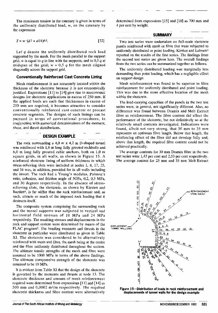
The rock surrounding a 4,0 m X 4,2 m D-shaped tunnelwas reinforced with 1,8 m long fully grouted rockbolts and6,0 m long fully grouted cable anchors, both on 1,0 msquare grids, in all walls, as shown in Figure 15. Areinforced shotcrete lining of uniform thickness in whichstress-relieving slots were included at nodes 1, 8, 17, 25,and 34 was, in addition, provided for in all walls includingthe invert. The rock had a Young's modulus, Poisson'sratio, cohesion, and friction angle of 5GPa, 0,2, 0,5 MPa,and 30 degrees respectively. In the absence of stress-relieving slots, the shotcrete, as shown by Kirsten andBartlett4, is far stiffer than the rock reinforcement and, assuch, attracts so much of the imposed rock loading that itdestructs itself.
The composite system comprising the surrounding rockand the tunnel supports was subjected to vertical andhorizontal field stresses of 10 MPa and 24 MParespectively. The resulting stresses and displacements in therock and support system were determined by means of theFLAC program5. The bending moments and thrusts in theshotcrete in particular were distributed as given in TableXI. The shot crete was considered to be alternativelyreinforced with mesh and fibre, the mesh being at the centreand the fibre uniformly distributed throughout the section.The ultimate tensile strengths of the mesh and fibre wereassumed to be 1000 MPa in terms of the above findings.The ultimate compressive strength of the shotcrete wasassumed to be 10 MPa.
It is evident from Table XI that the design of the shotcreteis governed by the moments and thrusts at node 13. Theshotcrete thickness and amount of mesh reinforcementrequired were determined from expressions [11] and [14] as500 mm and 0,0002 m2/m respectively. The requiredshotcrete thickness and fibre content were alternatively
determined from expressions [15] and [18] as 700 mm and4 per cent by weight.
~~ ~--~-----
SUMMARY~
---~----
Two test series were undertaken on full-scale shotcretepanels reinforced with mesh or fibre that were subjected touniformly distributed or point loading. Kirsten and Labrum1reported on the results of the first series. The findings fromthe second test series are given here. The overall findingsfrom the two series can be summarized together as follows.
The uniformly distributed loading was marginally lessdemanding than point loading, which has a negligible effecton support design.
Mesh reinforcement was found to be superior to fibrereinforcement for uniformly distributed and point loading.This was due to the more effective location of the meshwithin the shotcrete.
The load-carrying capacities of the panels in the two testseries were, in general, not significantly different. Also, nodifference was found between Dramix and Melt Extractfibre as reinforcement. The fibre content did affect theperformance of the shotcrete, but not definitively so at therelatively small contents investigated. Indications werefound, albeit not very strong, that 30 mm to 35 mmrepresents an optimum fibre length. Below that length, thereinforcing effect of the fibre did not develop fully and,above that length, the required fibre content could not beachieved practically.
The average contents for 30 mm Dramix fibre in the twotest series were 1,43 per cent and 2,53 per cent respectively.The average content for 25 mm and 35 mm Melt Extract
,.,N
"''""'Q
"''"
r REINFORCEMENT
/LOAD (kN/m)
\~
42 39 30 13
1'1
'"~0;0
;;;
'".....
Figure 1S-Distribution of loads in rock reinforcement anddisplacements of tunnel walls for the design example
Journal of The South African Institute of Mining and Metallurgy NOVEMBER/DECEMBER 1992 321

Node' Thrustt Moment* Node' Thrustt MomenH
kN/m kN/m kN/m kN/m---~ ~-~
--..-
--~~- f----
1 2887 0 18 3920 02 1816 -84 19 3098~ -973 2250 19 20 3618 -54 2365 40 21 3598 -25 2229 76 22 3581 26 2623 59 23 3156 -57 2602 -22 24 3849 -908 0 25 09 770 0 26 2230 010 3237 -126 27 2091 48811 3264 -406 28 1637 70612 3349 -413 29 1452 72213 3303 -435 30 1174 64014 3480 -354 31 1162 48215 3229 -294 32 606 32016 4082 -237 33 1039 8117 0 34 0
Table XI
Distributions of bending moment and thrust in a multiple stress-relievedshotcrete tunnel lining
,Figure 15 gives the relative locations of the nodes
t The thrust represents the average between the node corresponding toentry and the next node:j: A negative sign denotes tension on the outside of the lining
fibre in the second test series was 1,29 per cent and for the50 mm Melt Extract fibre 0,83 per cent. Despite closecontrol during the manufacturing process, neither theconsistency nor the target fibre content, 3 per cent byweight, could be obtained. It appeared from both test seriesthat an average content of about 1,5 per cent by weight isthe maximum that can be achieved in practical miningapplications for fibre lengths not exceeding 35 mm. Atgreater lengths, the maximum fibre content can be expectedto be less.
Shotcrete is much stiffer than rock reinforcement in thecontext of an application to the surface of an undergroundexcavation. It consequently attracts the greater proportionof the load in heavily converged ground, and destructs itselfin the process. Under these circumstances, fibre-reinforcedshotcrete is less attractive than mesh-reinforced shotcretebecause of the latter's ability to sustain larger deformations.Notwithstanding, fibre-reinforced shotcrete may yet be anattractive means to ensure the early safety of a workplace.
Civil-engineering projects on which quality assurance iscontrolled contractually, seem to be the only applications inwhich the sophisticated attributes of fibre-reinforcedshotcrete can be exploited effectively.
The surface stresses measured in the shotcrete in thesecond series varied owing to the complexity of the stressdistributions in the test panels. However, their ultimatevalues were, on average, comparable with the shotcretestrengths determined from the control beams. Thissupported the notion that both types of panel, mesh- andfibre-reinforced, were under-reinforced. The amount ofsteel contained in the mesh on its own represented an over-reinforced condition. Its unfurling profile and theaccompanying extensive strains, however, effectivelyamounted to an under-reinforced condition. The quantity ofsteel represented by the fibre was very small, and was
equivalent to an under-reinforced condition in theconventional sense.
The ultimate stresses measured in the panels were onlyabout 10 per cent of the cube strength. This was due to thenon-uniformity of the stresses in the test cubes, and to theanisotropy of the shotcrete strength as a function of thedirection of shooting. The cubes were crushed in thedirection of shooting, whereas the shotcrete in the panelsfailed under bending in the direction transverse to shooting,that is, the weaker direction.
The effective loads and thicknesses derived on theassumption that the shotcrete strained ideally plastically inthe post-peak stage enabled expressions for the ultimateflexural strength of the shotcrete, mesh- or fibre-reinforced,to be rigorously formulated. The surface stresses measuredconfirmed these derivations. In addition, the expressionswere extended to enable reinforced shotcrete that wassubjected simultaneously to bending and thrust to bedesigned rigorously.
Under conditions of extreme loading, reinforced shotcreteis not economically viable nor practically feasible. Thesurface of the excavation can in such cases be supportedonly by woven wire mesh pinned on a regular grid to therock surface. In conclusion, a rigorous design procedure forthe mesh in catenary action is given for this purpose.
~-
~
~---~
--
ACKNOWLEDGEMENTS---~
The permission of De Beers Consolidated Limited,Premier Mine Division, to publish this paper is gratefullyacknowledged. The assistance of Mr Pat Bartlett, ResidentGeologist at Premier Mine, and of Mr Peter Labrum, afellow member of staff, is sincerely appreciated.
REFERENCES--
~~. ~.---1. KIRSTEN, H.A.D., and LABRUM, P. R. The equivalence of fibre and
mesh reinforcement in the shotcrete used in tunnel-support systems. J.S. Afr. Inst. Min. Metal/., vol. 90. no. 7. Jul. 1990. pp. 153-171.
2. ASTM Committee C-9 and Sub-Committee C09.O3.04. Standard testmethod for flexural toughness and first-crack strength of fibre-rein-forced concrete (using beams with three point loading). Designation:C 1018-85. 1985. pp. 637-644.
3. WHITNEY,c.S. Plastic theory of reinforced concrete design. Trans.Am. Soc. Civ. Engrs, vol. 107. 1942. p. 251.
4. KIRSTEN, H.A.D., and BARTLEIT, PJ. Rigorously determined supportcharacteristics and support-design method for tunnels subject to squeez-ing conditions. J. S. Afr. Inst. Min. Metal/., vol. 92, no. 7. Jul. 1992. pp.195-214.
5. CUNDALL, P.A. Explicit finite difference methods in geomechanics.Proceedings EF Conference on Numerical Methods in Geomechanics.Blacksburg (USA), 1976. pp. 132-150.
ADDENDUM: DEFINITION OF SYMBOLS ANDABBREVIATIONS
(J
WStressTotal load on shotcrete panel demarcated by fixingrockbolts/anchorsConstant signifying point loading [16], oruniformly distributed loading [32], on shotcretepanelApplied in-plane bending moment and thrust onshotcreteBending moment capacity of shotcreteOverall thickness of shotcreteSpan of shotcrete panel between points of support
b
'p, Q
MHL
322 NOVEMBER/DECEMBER 1992 Journal of The South African Institute of Mining and Metallurgy

a Relative depth and shape of compressive-stressblock in shotcreteRelative depth of compressive-stress block inshotcreteSpan-to-thickness ratioUnit cross-sectional area of mesh reinforcementFibre content in shotcrete by volumeCumulative thickness of fibre in depth of panelGrid spacing of rockbolts/anchorsAperture and profile height of mesh reinforcement
~
r
AmC
a1,]
g
dh
Length in catenary of mesh reinforcementLatus rectum of catenaryRise of catenaryUniformly distributed rock load on shotcreteCorresponding uniformly distributed load on meshreinforcement in catenaryMaximum tension in catenarySubscript designating shotcreteSubscript designating mesh reinforcementSubscript designating fibre reinforcement
wq
T
m
AS&TS-the voice of science, engineering and technology-- -- - - - ----
INTRODUCTION--- --- -------------
AS&TS has embarked upon certain restructuring. Duringthe recent past we have concentrated on serving ourmembers by focusing our operations more effectively onthe core purpose of serving the broad common interests ofscience, engineering and technology.
--- --- -- --
MISSION AND FUNCTIONS- ------
The Mission of AS&TS reads: "To serve as a focal pointfor science and technology in South Africa; to promote co-operation among the entire scientific and engineeringcommunity so that science and technology can be advancedand applied for the benefit of all the peoples of the country;and to serve the interest of the members and membersocieties of AS&TS".
AS&TS has 16 Member Societies with a totalmembership of about 30 000 covering all of science,engineering and technology.
It is in a unique position to focus the views, needs andinterests of science, engineering and technology (SET) atthis critical time in our history. SET is neglected in oureducation system and social values, to the detriment ofsociety and the economy.
AS&TS serves to principal functions in the interest of itsMember Societies:
Management of the Observatory establishment andproviding accommodation, secretarial and accountingservices to member societies.
The Learned Society function, transcending individualSET boundaries, through the Committee for Science andTechnology.
------------
THE OBSERVATORY CAMPUS- --- ---
This campus represents a major asset of which allMember Societies are the ultimate beneficiaries, and asplendid home which is increasingly becoming recognizedas the address of science and engineering, at whichmeetings can be held and to which we can be proud toinvite visitors.
AS&TS is the owner and custodian of this property in theinterests of its members. It is our policy to offeraccommodation and services to members at break-evenrentals and charges which are market-related. We wish tocreate a sense of co-ownership of these assets in theinterests of the stakeholders.
-------------- --
THE LEARNED SOCIETY----
While the specialized interests of the various scientificand engineering disciplines and sub-disciplines are amplycatered for by the various societies that exist for thispurpose (most which are members of AS&TS), and whilethe sectoral interests of science and engineering areprovided for by lCSS and SAVI as 'umbrella' bodies,AS&TS is the only society that provides that vital formallink between science and engineering. Hence the learnedsociety role of AS&TS is of paramount national importance.
The Committee for Science and Technology provides theforum for fulfilment of this role. The committee has beenreconstituted this year, in consultation with SAVI andlCSS, to comprise four representatives each of AS&TS,SAVI and lCSS. There is already evidence of positiveresults" in terms of policy formulation and action beingachieved by this unique forum.
EDUCATION POLICY FOR TECHNOLOGY
A major priority this year is the Education Policy forTechnology initiative. The objective is to provide a meansfor science, engineering and technology to contribute to thewider debate about a restructured education policy forSouth Africa.
A Task Committee has been established under theCommittee for Science and Technology and two Saturdaymorning workshops sessions have been held at Eskom'sLeadership Development Centre to develop strategies andaction plans. About 60 representatives of the MemberSocieties attended and the very productive workshopsessions resulted in a summary document defining issues,strategies and action plans.
The objective is to establish an effective process withinthe SET societies to ensure that SET policy and prioritiesare effectively articulated, communicated and included in arestructured education system for South Africa, accordingto an agreed vision.
The following five leverage groups were established,namely:
Education PolicyProfessional MobilizationEngineering Curricula and MethodsTertiary EducationPromotion of SET.
Journal of The South African Institute of Mining and Metallurgy 323NOVEMBER/DECEMBER 1992

Action plans and positions papers will be developed to bepresented at a follow-up workshop in March 1993involving wider participation which will include industry,trade unions, education authorities and political players.
We believe that a once-off window of opportunity will beprovided within the national negotiation process for SouthMrica to develop a restructured education policy. We mustbe prepared to present the case for more appropriateemphasis to be placed on maths, science and technology aspriorities for life skills and economic upliftment.
_u_--------
OTHER AS& TS ACTIVITIES------ -----
Other AS&TS functions include the following:. the AS&TS National Award is presented annually tomark outstanding achievements in the fields of scienceand engineering. The Awards Function is a highlight ofour calendar and previous recipients truly represent aWho's Who of science and engineering endeavour inSouth Mrica;
Supplied by The Associated Scientific and Technical Societies ofSouth Africa, 18A Gill Street, Observatory 2198, Transvaal.
. financial support for the Athenaeum Trust in Cape Town,
which allows certain of our Member Societies the benefitsof utilizing these facilities;. participation in the National Youth Science Week
Olympiad, which is a shop window for school sciencedevelopments;. providing good quality meeting rooms and conference
facilities to members at minimal cost.
CONCLUSION----------- -- -------
AS&TS is in an important position to serve the broadinterest of science and engineering at a time when this is ofcrucial national importance.
Our objective is to focus on those issues which are ofnational significance and to mobilize the expertise withinthe member societies. It is initially important for AS&TS tobecome a relevant player recognized by decision makersand government. A particular priority being addressed isour relevance for the disadvantaged sections of society whohave been under-represented in Science and Engineering.
Errata - August/September 1992-;ssueWith reference to the August/September 1992 issue of
the Journal of The South African Institute of Mining andMetallurgy (Vol. 92, No. 8/9), the complete version of thepreamble presented by the incoming President, Mr J.P.Hoffman, was not transcribed and therefore not published.It was as follows:
Incoming President: Thank you Richard, for thatintroduction. It is a great honour for me to lead the Instituteas President for the 98/99th year of our Institute.
Richard, you have led us with confidence and verywisely during your year in office. There are a number ofissues that progressed very well, and which I think youwould like to see finalized this coming year-issues suchas our relationship with SAVI and other Associations,Societies, and Institutes with the same generic interest andbackground as our own. Fortunately, you as immediate PastPresident will still be around and in a good position tomake a very important contribution in this regard.
Angela, I thank you for the support you have givenRichard. He was a busy man, often away from home orbusy with institute matters. We often forget that the womanin a man's life has to cope with what becomes his first'love'-the Institute. Angela, you may now have Richardback on a full-time basis (almost).
Richard, it now gives me great pleasure, on behalf ofCouncil and all Members of this Institute, to present youwith our traditional plaque, properly inscribed, as amomento of your year of office.
Ek sien uit na my diensjaar as President van hierdieInstituut met die wete dat ek kan staat maak op die hulp enondersteuning van die Raad en van al die gewese Presidentewat aangedui het dat hulle op die Raad sal aanbly. To knowthat the experience, expertise, and wisdom of our PastPresidents still serving on Council is there to tap, is veryreassuring and comforting.
My congratulations to our incoming Council and, inparticular, a warm welcome is extended to those Membersjoining Council for the first time. Our thanks also to thoseMembers, even though they were not elected to serve onCouncil this time, for their willingness to serve on variouscommittees. Indeed, it is this attitude of its Members thatmakes this Institute something special.
I also know that, with loyal support as displayed by theSecretariat the past number of years, the 1992/93 Councilyear will be a good year. Even if things become rough andtough, I know you can and will persevere.
The gratitude of our Institute is also due to the employersof our Office Bearers and Members of Council. Withouttheir support, there would be no time to participate inInstitute matters. In particular I thank Columbus JointVenture (formerly Middelburg Steel and Alloys) forallowing me the time to lead this Institute as President forthe next year.
Ek wil ook my vrou, Hanneke en my kinders bedank virdie ondersteuning wat ek van julle deur die jare ontvanghet, en ek weet, nog sal ontvang.
I undertake to serve this Institute to the best of myabilities, in order to satisfy the key objectives of thisInstitute as per our Constitution.
Also in a supporting role is a very competent group ofOffice Bearers and it gives me pleasure to welcome DonRoss-Watt to Office Bearers as Junior Vice President, andto invite him to join us here on the rostrum.
We apologise for the misspelling of Mr William Bettel'sname on page 221 of the August/September 1992 issue ofthe Journal of The South African Institute of Mining andMetallurgy (Vol. 92, No. 8/9).
324 NOVEMBER/DECEMBER 1992 Journal of The South African Institute of Mining and Metallurgy