comparison between pst-upfc and ipfc on power...
TRANSCRIPT

Australian Journal of Basic and Applied Sciences, 5(7): 711-723, 2011ISSN 1991-8178
Corresponding Author: Naser parhizgar,Department of Electrical Engineering, Science and Research Branch, IslamicAzad University, Fars, Iran, E-mail: [email protected]
711
Comparison between PST-UPFC and IPFC on Power Flow Control and ProfileVoltage in Power System
Naser Parhizgar, Zahra Dehghani, Mehdi Roopaei, Parisa Esfandiar
Department of Electrical Engineering, Science and Research Branch, Islamic Azad University,Fars, Iran
Abstract: This paper presents a comparison study between the applications of the Unified Power FlowController (UPFC) and the Interline Power Flow Controller (IPFC) and Phase Shifting Transformer(PST) in optimal power flow (OPF) control. The power injection models of the flexible ACtransmission systems (FACTS) devices are reviewed and incorporated in the OPF problem withoutactive power generation redispatching, which minimizes the overall generating cost. The FACTSdevices are planned for power flow regulation and their additional degrees of freedom act as additionalpotential in optimizing the power system. The performance of the UPFC and the IPFC is comparedfrom the viewpoint of the total active power losses and their necessary capacities through numericalexamples. The feasibility of a gradient-based algorithm, namely sequential quadratic programming(SQP), is tested, and the importance and some techniques of proper selection of the initial optimizationconditions are also presented.
Key word: Index Terms-FACTS, IPFC, OPF, UPFC, PST
INTRODUCTION
The emergence of the FACTS devices offers great opportunities to the operation and control of modempower systems. For example, in the steady-state operation, FACTS devices are often planned for power flowregulation to improve the transfer capability of existing transmission lines.
Traditionally, FACTS devices can only regulate either the active power flow or reactive power flow ofa single transmission line. A breakthrough is made by the availability of the UPFC, which is one of the mostversatile FACTS devices and is capable to control the active and reactive power flows in the transmission lineat the same time. Another newly developed FACTS device, namely the IPFC, further extends the capabilityof independently influencing the active and reactive power flows to simultaneous compensation of multipletransmission lines. These significant functions are made possible by the combination of multiple compensatorscoupled via a common dc link. Thus, both the UPFC and the IPFC are defined as the combined compensators.Recently, due to the problems such as the congestion management, the minimization of the operational costand the overall generating cost, the additional control freedoms of FACTS devices have aroused great interestin the application of FACTS devices especially the UPFC the IPFC and FACTS device especially the UPFC,the IPFC can the generalized unified power flow controller (GUPFC), in the OPF control. However, very fewpublications have been focused on the comparison between the performance of the UPFC and the IPFC in theOPF control. Therefore, the study on such a comparison is presented in this paper, in which the OPF controlincorporating either a UPFC or an IPFC has the same optimization objective and is subject to the same powerflow regulation constraints.
Proper modeling of the FACTS devices is very important to the success of the corresponding OPFcalculation. In this paper, the power injection models of the UPFC and the IPFC and PST are adopted andreviewed in sections 2-4, because they do not destroy the symmetric characteristics of the admittance matrixand are very convenient to be incorporated in OPF programs. In the next a common OPF problemincorporating combined compensators is outlined. This kind of problems, which are essentially nonlinearoptimization problems, can be solved by linear programming (LP), SQP, the Newton's method and thenonlinear interior point method and allows the inclusion of inequality constraints without barrier functions orinterior methods , it is used to carry out the numerical simulations as presented in section 4. It is natural thatsuitable initialization of the voltage-sourced converters (VSCs) is mandatory for the gradient-based algorithms

Aust. J. Basic & Appl. Sci., 5(7): 711-723, 2011
712
such as SQP due to the strong nonlinearity and no convexity of these combined compensators. Thus, analyticalsolution to initialize the series VSC is also reviewed in section 2. In the case of the GUPFC with all its seriesVSCs were being subject to both the active and reactive branch power constraints and its shunt VSC beingsubject to local voltage magnitude control constraints.
However not of pervious work have not been comparised between PST and IPFC and UPFC on powerflow problem in power system.
2. Interline power Flow Controller (IPFC):2.1. Operating Principle of IPFC:
In its general form the inter line power flow controller employs a number of dc-to-ac converters eachproviding series compensation for a different line. In other words, the IPFC comprises a number of StaticSynchronous Series Compensators (SSSC). The simplest IPFC consist of two back-to-back dc-to-ac converters,which are connected in series with two transmission lines through series coupling transformers and the dcterminals of the converters are connected together via a common dc link as shown in Fig.1.With this IPFC,in addition to providing series reactive compensation, any converter can be controlled to supply real power tothe common dc link from its own transmission line [11].
Fig. 1: Schematic diagram of two converters IPFC
2.2. Mathematical Model of IPFC:In this section, a mathematical model for IPFC which will be referred to as power injection model is
derived. This model is helpful in understanding the impact of the IPFC on the power system in the steadystate. Furthermore, the IPFC model can easily be incorporated in the power flow model. Usually, in the steadystate analysis of power systems, the VSC may be represented as a synchronous voltage source injecting analmost sinusoidal voltage with controllable magnitude and angle. Based on this, the equivalent circuit of IPFCis shown in Fig.2.
Fig. 2: Schematic representation of IPFC(a) Equivalent circuit of two converter IPFC (b) Power injection model of two converter IPFC
In Fig.2, Vi, Vj and Vk are the complex bus voltages at the buses x=i,j and k respectively, defined as
is the complex controllable series injected voltage source, defined as Vsein = Vsein pθsein( , , ).i i inV x i j k Vse
(n=j,k ) and Zsein (n=j,k ) is the series coupling transformer impedance. The active and reactive powerinjections at each bus can be easily calculated by representing IPFC as current source. For the sake ofsimplicity, the resistance of the transmission lines and the series coupling transformers are neglected. Thepower injections at buses are summarized:

Aust. J. Basic & Appl. Sci., 5(7): 711-723, 2011
713
The equivalent power injection model of an IPFC is shown in Fig.2-a neither absorbs nor injects activepower with respect to the ac system; the active power exchange between the converters via the dc link is zero,
Where the superscript * denotes the conjugate of a complex number. If the resistances of seriestransformers are neglected, (5) can be written as:
Normally in the steady state operation, the IPFC is used to control the active and reactive power flowsin the transmission lines in which it is placed.
The active and reactive power flow control constraints are:
Where n=j, k; , are the specified active and reactive power flow control references respectively,,Spec Specni niP Q
and
Thus, the power balance equations are as follows:
Where are generations active and reactive powers, are load active and reactivegm gmP and Q lm lmP and Q
powers. , are conventional transmitted active and reactive powers at the bus m=i, j and k., ,line m line mP and Q
3. Unified Power Flow Controller (UPFC):3.1. Characteristics of UPFC:
Line outage, congestion, cascading line tripping, power system stability loss are the major issues wherecapability and utilization of FACTS are noticed. Representative of the last generation of FACTS devices is theUnified Power Flow Controller (UPFC). The UPFC is a device which can control simultaneously all threeparameters of line power flow (line impedance, voltage and phase angle). Such "new" FACTS device combinestogether the features of two "old" FACTS devices: the Static Synchronous Compensator (STATCOM) and theStatic Synchronous Series Compensator (SSSC). In practice, these two devices are two Voltage Source Inverters(VSI’s) connected respectively in shunt with the transmission line through a shunt transformer and in serieswith the transmission line through a series transformer, connected to each other by a common dc link including
Aust. J. Basic & Appl. Sci., 5(7): 711-723, 2011
714
a storage capacitor. The shunt inverter is used for voltage regulation at the point of connection injecting anopportune reactive power flow into the line and to balance the real power flow exchanged between the seriesinverter and the transmission line. The series inverter can be used to control the real and reactive line powerflow inserting an opportune voltage with controllable magnitude and phase in series with the transmission line.Thereby, the UPFC can fulfill functions of reactive shunt compensation, active and reactive series compensationand phase shifting. Besides, the UPFC allows a secondary but important function such as stability control tosuppress power system oscillations improving the transient stability of power system. As the need for flexibleand fast power flow controllers, such as the UPFC, is expected to grow in the future due to the changes inthe electricity markets, there is a corresponding need for reliable and realistic models of these controllers toinvestigate the impact of them on the performance of the power system. In this article emphasis is laid toproject the use of UPFC in transmission link to increase the power flow and to improve the voltage profileof the system using MATLAB SIMULINK.
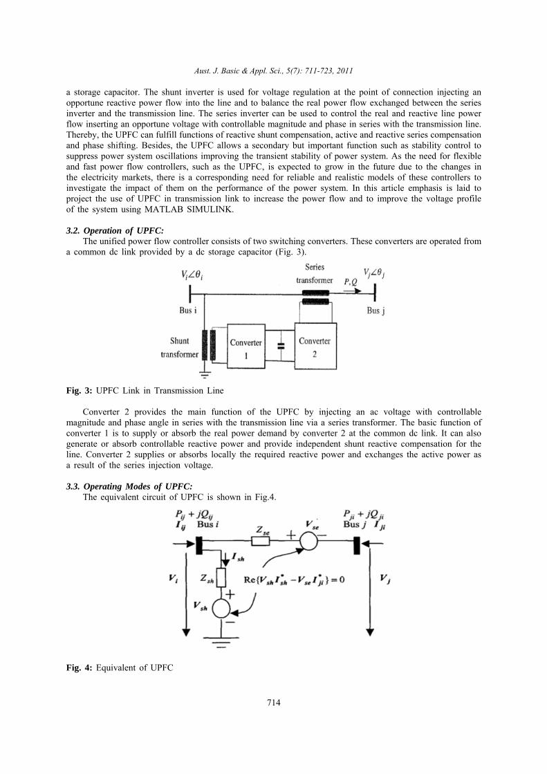
3.2. Operation of UPFC:The unified power flow controller consists of two switching converters. These converters are operated from
a common dc link provided by a dc storage capacitor (Fig. 3).
Fig. 3: UPFC Link in Transmission Line
Converter 2 provides the main function of the UPFC by injecting an ac voltage with controllablemagnitude and phase angle in series with the transmission line via a series transformer. The basic function ofconverter 1 is to supply or absorb the real power demand by converter 2 at the common dc link. It can alsogenerate or absorb controllable reactive power and provide independent shunt reactive compensation for theline. Converter 2 supplies or absorbs locally the required reactive power and exchanges the active power asa result of the series injection voltage.
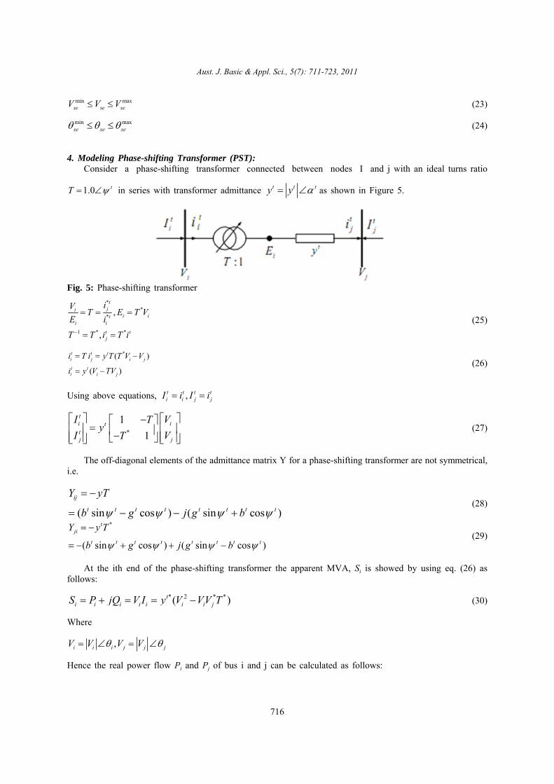
3.3. Operating Modes of UPFC:The equivalent circuit of UPFC is shown in Fig.4.
Fig. 4: Equivalent of UPFC

Aust. J. Basic & Appl. Sci., 5(7): 711-723, 2011
715
According to the equivalent circuit, suppose and ., ,se se sh sh i iV V V j jV
Then the power flow constraints of the UPFC are:
(13)
2 ( cos sin )
( cos( ) sin( ))
( cos( ) sin( ))
ij i ii i j ij ij ij ij
i se ij i se ij i se
i sh sh i sh sh i sh
P V g VV g b
VV g b
VV g b
(14)
2 ( sin cos )
( sin( ) cos( ))
( sin( ) cos( ))
ij i ii i j ij ij ij ij
i se ij i se ij i se
i sh sh i sh sh i sh
Q V b VV g b
VV g b
VV g b
(15)
2 ( cos cos )
( cos( ) sin( ))
ji j jj i j ij ji ij ji
i se ij j se ij j se
P V g VV g b
VV g b
(16)
2 ( sin cos )
( sin( ) cos( ))
ji j jj i j ij ji ij ji
i se ij j se ij j se
Q V b VV g b
VV g b
where 1/ , 1/ ,
, , , .sh sh sh se se se
ii ij sh ii ij sh jj ii jj ii
g jb Z g jb Z
g g g b b b g g b b
Operating constraint of the UPFC (active power exchange between two inverters via the DC link) is:
or* *Re( ) 0sh sh se jiPE V I V I
(17)
2
2
( cos( )
sin( ))
( cos( ) sin( ))
( cos( ) sin( )) 0
sh sh i sh sh i sh
sh i sh se ij
i se ij i se ij i se
j se ij j se ij j se
V g VV g
b V g
VV g b
V V g b
The bus voltage control and active and reactive power flow control constraints are as follows,
(18)0Specifiedi iV V
(19)0Specifiedji jiP P
(20)0Specifiedji jiQ Q
Where is the specified bus voltage.SpecifiediV
are specified active and reactive power flow, respectively.,Specified Specifiedji jiP Q
The basic operating control mode is given by (20)-(22). However, implementation of a comprehensiveUPFC model with various advanced control modes can be found. The two equivalent voltage injection Vse,pθse, Vsh pθse bounds constraints:
(21)min maxsh sh shV V V
(22)min maxsh sh sh
Aust. J. Basic & Appl. Sci., 5(7): 711-723, 2011
716
(23)min maxse se seV V V
(24)min maxse se se
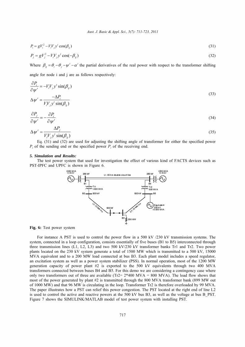
4. Modeling Phase-shifting Transformer (PST):Consider a phase-shifting transformer connected between nodes I and j with an ideal turns ratio
in series with transformer admittance as shown in Figure 5. 1.0 tT t t ty y
Fig. 5: Phase-shifting transformer
(25)
**
*
1 * *
,
,
tji
i iti i
t tj
iVT E T V
E i
T T i T i
(26)*( )
( )
t t ti j i j
t ti i j
i T i y T T V V
i y V TV
Using above equations, ,t t t t
i i j jI i I i
(27)*
1
1
ti ittj j
I VTy
I VT
The off-diagonal elements of the admittance matrix Y for a phase-shifting transformer are not symmetrical,i.e.
(28)( sin cos ) ( sin cos )
ij
t t t t t t t t
Y yT
b g j g b
(29)*
( sin cos ) ( sin cos )
tji
t t t t t t t t
Y y T
b g j g b
At the ith end of the phase-shifting transformer the apparent MVA, Si is showed by using eq. (26) asfollows:
(30)* 2 * *( )ti i i i i i i jS P jQ V I y V VV T
Where
,i i i j j jV V V V Hence the real power flow Pi and Pj of bus i and j can be calculated as follows:
Aust. J. Basic & Appl. Sci., 5(7): 711-723, 2011
717
(31)2 cos( )ti i i j ijP gV VV y
(32)2 cos( )tj j i j ijP gV VV y
Where the partial derivatives of the real power with respect to the transformer shiftingt tij i j
angle for node i and j are as follows respectively:
(33)
sin( )
sin( )
tii j ijt
t it
i j ij
PVV y
P
VV y
(34)j it t
P P
(35)sin( )
jtt
i j ij
P
VV y
Eq. (31) and (32) are used for adjusting the shifting angle of transformer for either the specified powerPi of the sending end or the specified power Pi of the receiving end.
5. Simulation and Results:The test power system that used for investigation the effect of various kind of FACTS devices such as
PST-IPFC and UPFC is shown in Figure 6.
Fig. 6: Test power system
For instance A PST is used to control the power flow in a 500 kV /230 kV transmission systems. Thesystem, connected in a loop configuration, consists essentially of five buses (B1 to B5) interconnected throughthree transmission lines (L1, L2, L3) and two 500 kV/230 kV transformer banks Tr1 and Tr2. Two powerplants located on the 230 kV system generate a total of 1500 MW which is transmitted to a 500 kV, 15000MVA equivalent and to a 200 MW load connected at bus B3. Each plant model includes a speed regulator,an excitation system as well as a power system stabilizer (PSS). In normal operation, most of the 1200 MWgeneration capacity of power plant #2 is exported to the 500 kV equivalents through two 400 MVAtransformers connected between buses B4 and B5. For this demo we are considering a contingency case whereonly two transformers out of three are available (Tr2= 2*400 MVA = 800 MVA). The load flow shows thatmost of the power generated by plant #2 is transmitted through the 800 MVA transformer bank (899 MW outof 1000 MW) and that 96 MW is circulating in the loop. Transformer Tr2 is therefore overloaded by 99 MVA.The paper illustrates how a PST can relief this power congestion. The PST located at the right end of line L2is used to control the active and reactive powers at the 500 kV bus B3, as well as the voltage at bus B_PST.Figure 7 shows the SIMULINK/MATLAB model of test power system with installing PST.

Aust. J. Basic & Appl. Sci., 5(7): 711-723, 2011
718
Fig. 7: Simulink model of test power system with PST in line L2
The variation of tap position, PST phase shift Ψ and active power transfer through bus B3 (power throughPST) and B4 (power through transformer Tr2) are reproduced on the figures 8-10 as below.
Fig. 8: The variation of tap position
Fig. 9: The variation of PST phase shift Ψ
Fig. 10: power active power transfer through bus B3 (power through PST) and B4 (power through transformerTr2)
Each tap change produces a phase angle variation of approximately 3 degrees, resulting in a 60 MW powerincrease through B3. At tap position -2, the power through transformer Tr2 as decreased from 900 MW to 775MW.The variations magnitudes and phase angles of power system buses before and after PST installing isshown in Tables 1.
Active and reactive power flow in transmission lines of power system before and after installing PST isshown in Table 2.

Aust. J. Basic & Appl. Sci., 5(7): 711-723, 2011
719
Table 1: Bus voltages (magnitude and angle) without and with PST in power systemBus Magnitude of Voltage(p.u) Angle of Voltage (rad)
------------------------------------------------------------------- ----------------------------------------------------------------Without PST With PST Without PST With PST
B1 0.9965 0.9914 0.2265 0.1360B2 0.9993 0.9925 0.1553 0.0420B3 0.9995 0.9947 0.1136 0.1265B4 0.9925 0.9932 0.2569 0.2222B5 0.9977 0.9963 0.0863 0.0863
Table 2: Real and Reactive power flow in transmission lines without and with PSTLine Active Power Reactive Power
------------------------------------------------------------------ ----------------------------------------------------------------Without PST With PST With PST With PST
L1 -47.7851 -68.1685 -16.277 -26.9573L2 -27.7851 -35.1685 -16.277 -36.9573L3 500.9965 663.2672 -70.5174 -76.8544L5 386.4439 427.7881 80.5257 63.4736
The simulation with IPFC and UPFC are implanted as shown in Figures 11 and 12.
Fig. 11: Simulink model of test power system with IPFC between lines L1 and L3
Fig. 12: Simulink model of test power system with UPFC between buses B1 and B2
Aust. J. Basic & Appl. Sci., 5(7): 711-723, 2011
720
The result of simulation with IPFC and UPFC such as voltage profile and real and reactive power floware listed in Tables 3-6.
Table 3: Bus voltages (magnitude and angle) without and with IPFC in power systemBuses voltage magnitude Buses Voltage angle---------------------------------------------------------------- ----------------------------------------------------------------
Bus without IPFC with IPFC (2-3) without IPFC with IPFC (2-3)B1 0.9965 0.9979 0.2265 0.172B2 0.9993 0.9928 0.1553 0.1842B3 0.9995 0.9955 0.1136 0.1278B4 0.9925 0.9991 0.2569 0.2163B5 0.9977 0.9976 0.0863 0.0859
Table 4: Real and reactive power Line flow without and with various locations of IPFC in power systemReal power flow lines Reactive power flow lines------------------------------------------------------------------ ----------------------------------------------------------------
line without IPFC with IPFC (2-3) without IPFC with IPFC (2-3)L1 -47.7851 -71.099 18.0234 12.0118L2 -27.7851 -40.4954 18.0234 95.9966L3 500.9965 683.9578 -27.7881 -88.376L5 386.4439 483.9559 21.5407 -53.3283
Table 5: Bus voltages (magnitude and angle) without and with UPFC in power system Buses voltage magnitude Buses voltage angle----------------------------------------------------------- ----------------------------------------------------------------
without UPFC with UPFC without UPFC with UPFCB1 0.9965 0.9967 0.2265 0.1745B2 0.9993 1.0018 0.1553 0.0911B3 0.9995 1.0009 0.1136 0.1202B4 0.9925 0.9942 0.2569 0.2364B5 0.9977 0.9988 0.0863 0.0859
Table 6: Real and reactive power Line flow without and with various locations of UPFC in power systemReal power flow lines Reactive power flow lines ------------------------------------------------------------- ----------------------------------------------------------------
lines without UPFC with UPFC3 without UPFC with UPFC4L1 -47.7851 -59.1473 18.0234 20.3157L2 -27.7851 -39.1473 18.0234 20.3157L3 500.9965 687 -27.7881 -27.8L5 386.4439 485.4452 21.5407 15.6074
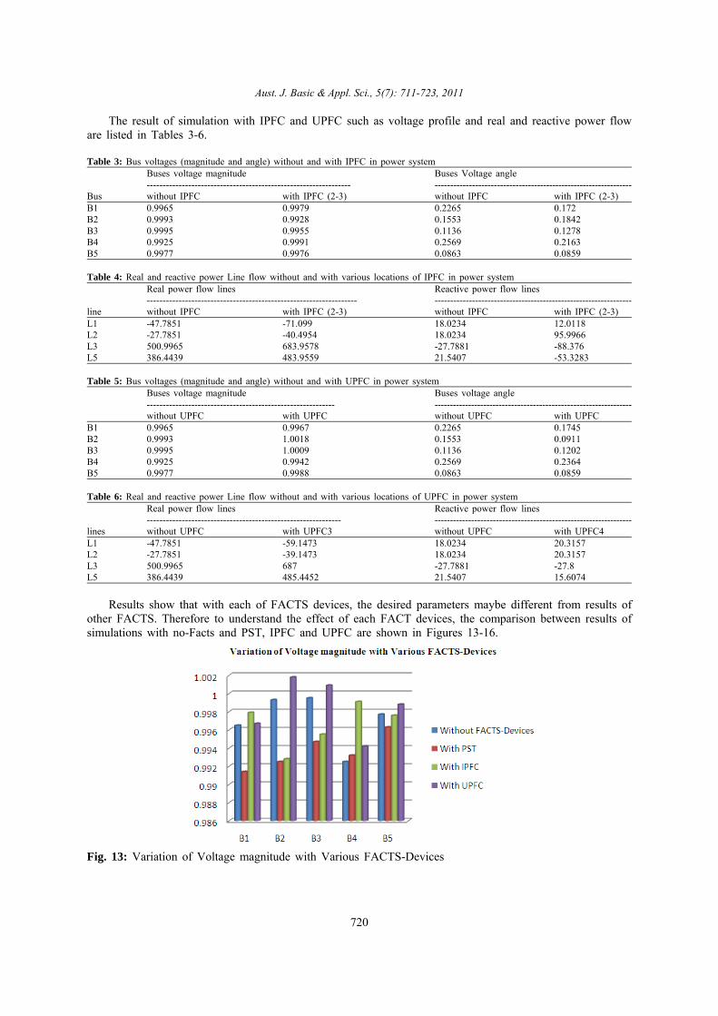
Results show that with each of FACTS devices, the desired parameters maybe different from results ofother FACTS. Therefore to understand the effect of each FACT devices, the comparison between results ofsimulations with no-Facts and PST, IPFC and UPFC are shown in Figures 13-16.
Fig. 13: Variation of Voltage magnitude with Various FACTS-Devices

Aust. J. Basic & Appl. Sci., 5(7): 711-723, 2011
721
Fig. 14: Variation of Voltage angle with Various FACTS-Devices
Fig. 15: Variation of active power flow in transmission lines with Various FACTS-Devices
Fig. 16: Variation of Reactive power flow in transmission lines with Various FACTS-Devices
Conclusion:The power injection models of PST-IPFC and UPFC are reviewed and implemented in an OPF problem.
With the proper selection of initial conditions, the proposed OPF problem, which optimizes the overallgenerating cost and is subject to the branch flow constraints of either the each kind of FACTS devices subjectto the branch power flow constraints, can be solved by the SQP algorithm. Some techniques to select initialvalues of the mentioned FACTS devices are presented as a supplement to the analytical solution. It is obviousthat all of FACTS devices presented above are powerful tools for power flow regulation, by which the transfercapability of the transmission line can be increased significantly. Combined with the generating bus voltageadjustment, the OPF incorporating either FACTS device can effectively minimize the overall generating costwithout active power generation redispatching. When PST is incorporated to control the active and reactivepower flows in a chosen transmission line, the effectiveness varies with the location of the PST without thebranch power flow constraints. The results show that by PST the profile of voltage and real and reactive power

Aust. J. Basic & Appl. Sci., 5(7): 711-723, 2011
722
flow in transmission lines can be improved. Also the results show that by UPFC the profile of voltage couldbe better and real and reactive power flow in transmission lines can be improved with IPFC.
REFERENCES
Carsten Lehmkoster, 2002. "Security constrained optimal power flow for aneconomical operation ofFACTS-devices in liberalized energy markets,"IEEE Trans. Power Delivery, 17: 603-608.
Enrique Acha, Claudio R. Fuerte-Esquivel, 2004. Hugo Ambriz-Perez, and Cesar Angeles-Camacho,FACTS Modelling and Simulation in Power Networks.West Sussex, England: John Wiley & Sons Ltd, pp:200-201, 227-228, 267-307.
Handschin, E. and C. Lehmkoster, 1999. "Optimal power flow for deregulatedsystems withFACTS-devices," in Proc. 13th Power Systems Computation Conf:, Trondheim, Norway, pp: 1270-1276.
Hingorani, N., 1991. “FACTS, Flexible Transmission Systems”, In Proceedings of Fifth InternationalConference on AC and DC Power Transmission, London, pp: 1-7.
Gyugyi, L., 1993. “Dynamic Compensation of AC Transmission Lines by Solid-state Synchronous VoltageSources”, Presented at IEEE Summer Meeting, No. 93 SM.
Gyugyi, L. et al, 1994. “The unified Power Flow Controller: A New Approach To Power TransmissionControl”, Presented at 1994 IEEE Summer Meeting, Paper No. 94-SM 474-7 PWRD.
Jun Zhang and Akihiko Yokoyama, 2006. "Optimal power flow for congestion management by interlinepower flow controller (IPFC)," submitted to2006 Int. Conf. on Power System Technology, Chongqing, China.
Lerch, E. et al, 1994. “ Simulation and Performance Analysis of Unified Power Flow Controller”, Cigre,session, Pages.
Mihalic, R. et al, “Improvement of Transient Stability Using Unified Power Flow Controller”, Presentedat IEEE Winter Meeting, Paper 95 WM 269-1 PWRD.
Narain, G. Hingorani and Laszlo Gyugyi, 2000. Understanding FACTS:concepts and technology offlexibleAC transmission systems. NewYork, NY: The Institute of Electrical and Electronics Engineers, p: 297.
Noroozian, M., 1997. L. Angquist, M. Ghandhari, and G. Andersson, "Use of UPFC for optimal powerflow control," IEEE Trans. Power Delivery, 12: 1629-1634.
Noroozian, M., 1993. Andersson, “Power Flow Control by Use of Controllable Series Components“, IEEETransactions on Power Delivery, 8(3): 1420-1429.
Noroozian, M., L. Angquist, M. Ghandhari and G. Andersson, 1997. "Use of UPFC for optimal powerflow control," IEEE Trans. Power Delivery, 12: 1629-1634.
Peng, Ye., Ye, Ying and Jiahua Song, 2004. "A reliable UPFC control method foroptimal power flowcalculation," in Proc. 2004 IEEE Power Engineering Society General Meeting, Denver, CO, pp: 1178-1183.
Stagg, G.W. and A. Abiad, “Computer Methods in Power System Analysis”, McGraw-Hill, New York,First Edition. 434-1 PWRD. 14-205.
Taranto, G.N., L.M.V.G. Pinto and M.V.F. Pereira, 1992. "Representation of FACTS devices in powersystem economic dispatch," IEEE Trans. Power Systems, 7: 572-576.
Taranto, G.N., L.M.V.G. Pinto and M.V.F. Pereira, 1992. "Representation of FACTS devices in powersystem economic dispatch," IEEE Trans. Power Systems, 7: 572-576.
Teerathana, S., A. Yokoyama, Y. Nakachi and M. Yasumatsu, 2005. "Anoptimal power flow controlmethod of power system by interline powerflow controller (IPFC)," in Proc. 7th Int. Power EngineeringConf,Singapore, pp: 1-6.
Venkataraman, P., 2002. Applied Optimization with Matlab Programming.New York, NY: John Wiley &Sons, p: 353.
Xiao-Ping Zhang, Edmund Handschin, and Maojun 2001. "Mike" Yao,"Modeling of the generalized unifiedpower flow controller (GUPFC) in a nonlinear interior point OPF," IEEE Trans. Power Systems, 16: 367-373.
Ying Xiao, Y.H. Song and Y.Z. Sun, 2000. "Power injection method andlinear programming for FACTScontrol," in Proc. 2000 IEEE PowerEngineering Society Winter Meeting, Singapore, pp: 877-884.
Zhang, X.-P. and E.J. Handschin, 2001. "Advanced implementation of UPFC in a nonlinear interior-pointOPF," IEE Proceedings-Generation,Transmission and Distribution, 148: 489-496.
Zhang, X-P. and E.J. Handschin, 2001. "Optimal power flow control by converter based FACTScontrollers," in Proc. 2001 7th Int. Conf: on AC-DC Power Transmission, London, United Kingdom, pp:250-255.
Zhang, X.-P., 2003. "Modelling of the interline power flow controller and the generalized unified powerflow controller in Newton power flow," IEE Proceedings-Generation, Transmission and Distribution, 150:268-274.