comparison of electrical output quantity of photovoltaic … · comparison of electrical output...
TRANSCRIPT
Research Journal of Engineering
Vol. 6(6), 13-18, June (2017)
International Science Community Association
Comparison of electrical output quantity of photovoltaic module through
boost converter in MATLABAnil Patel
2
AvailableReceived 8th April
Abstract
Solar PV module is a conversion technology in which solar power is converted to direct current (DC) electricity and boost
converter is a device which is use for enhance the DC voltage and current amplitude. Converter based solar PV module,
requires two weather data, radiation and temperature in the form of input variables and the output can be voltage, current,
or power. In this paper, stepwise process of mathematical modelling of converter based solar PV module are described, in
which weather data (Irradiance and temperature) has been used as input and comparison of output between PV Module and
Boost Converter has been performed that how the generated power of PV Module is increased by using Boost Converter. All
the simulation work has been performed in MAT
Keywords: PV Module, Boost Converter, Irradiance, Temperature, Power, MATLAB/Simulink.
Introduction
In the field of renewable energy, solar energy is most trifling,
utilizable non-conventional energy; occur liberally in our
environment that leads to the photovoltaic (PV) effects.
Photovoltaic word is a combination of photo and voltaic.
‘Photo’ that means light and ‘Voltaic’ that tends to create
electrical energy. Therefore the PV module produces the
electricity directly from sunlight1. Photovoltaic provides the
user with the ability to produce power in a quiet, clean and
consistent way. For environment reference PV module is
connected to boost converter. Therefore converter based PV
solar modules are steadily interesting to admissible in our
community.
They are usually allowed for standalone or grid related
applications. It has become god’s gift for the rural community
for which electricity had become a dreamy thing
mathematical modeling of Converter based PV Module has been
continuously rebuilt so that the investigator can i
understanding of functionality. In this paper, stepwise process of
converter based PV module simulation is described by using
mathematical equations, which are generated from their
schematic diagrams. For the purpose of simulation, Simulink
toolbar from MATLAB has been used extensively. Almost all
the components, and blocks were used which are available in
Simulink toolbar.
Mathematical modelling and presentation of PV
module
The schematic diagram of equivalent circuit of solar cell and
module are shown below3:
Engineering Sciences ___________________________________________
Association
Comparison of electrical output quantity of photovoltaic module through
boost converter in MATLAB-simulink environmentAnil Patel
1*, Albert John Varghese
2 and Soma Rajwade
2
1RCET Bhilai, CG, India 2Department of ELE, RCET Bhilai, CG, India
Available online at: www.isca.in, www.isca.me April 2017, revised 9th June 2017, accepted 24th June 2017
Solar PV module is a conversion technology in which solar power is converted to direct current (DC) electricity and boost
converter is a device which is use for enhance the DC voltage and current amplitude. Converter based solar PV module,
ther data, radiation and temperature in the form of input variables and the output can be voltage, current,
or power. In this paper, stepwise process of mathematical modelling of converter based solar PV module are described, in
nce and temperature) has been used as input and comparison of output between PV Module and
Boost Converter has been performed that how the generated power of PV Module is increased by using Boost Converter. All
the simulation work has been performed in MATLAB/Simulink environment.
PV Module, Boost Converter, Irradiance, Temperature, Power, MATLAB/Simulink.
In the field of renewable energy, solar energy is most trifling,
conventional energy; occur liberally in our
environment that leads to the photovoltaic (PV) effects.
Photovoltaic word is a combination of photo and voltaic.
‘Photo’ that means light and ‘Voltaic’ that tends to create
electrical energy. Therefore the PV module produces the
. Photovoltaic provides the
y to produce power in a quiet, clean and
consistent way. For environment reference PV module is
connected to boost converter. Therefore converter based PV
solar modules are steadily interesting to admissible in our
standalone or grid related
applications. It has become god’s gift for the rural community
for which electricity had become a dreamy thing2. The
mathematical modeling of Converter based PV Module has been
continuously rebuilt so that the investigator can improve its
understanding of functionality. In this paper, stepwise process of
converter based PV module simulation is described by using
mathematical equations, which are generated from their
schematic diagrams. For the purpose of simulation, Simulink
bar from MATLAB has been used extensively. Almost all
the components, and blocks were used which are available in
Mathematical modelling and presentation of PV
The schematic diagram of equivalent circuit of solar cell and
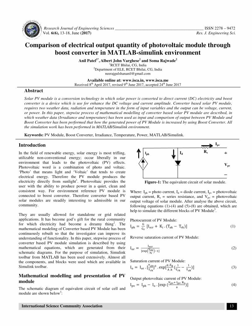
Where: Iph = photo current, Id = diode current, I
output current, Rs = series resistance, and V
output voltage of solar module. After analyse
following equations (1)-(4) and (5)
help to simulate the different blocks of PV Module
Photocurrent of PV Module:
I I K. T T
Reverse saturation current of PV Module:
I !"#
Saturation current of PV Module:
I I. $ %$%&. exp*.+,-.
#$%
#$ %
Output photovoltaic current of PV Module:
I. I I. exp/01201.3
Id Iph
Figure-1: The equivalent circuit of solar module
________ ISSN 2278 – 9472
Res. J. Engineering Sci.
13
Comparison of electrical output quantity of photovoltaic module through
simulink environment
Solar PV module is a conversion technology in which solar power is converted to direct current (DC) electricity and boost
converter is a device which is use for enhance the DC voltage and current amplitude. Converter based solar PV module,
ther data, radiation and temperature in the form of input variables and the output can be voltage, current,
or power. In this paper, stepwise process of mathematical modelling of converter based solar PV module are described, in
nce and temperature) has been used as input and comparison of output between PV Module and
Boost Converter has been performed that how the generated power of PV Module is increased by using Boost Converter. All
= diode current, Ipv = photovoltaic
= series resistance, and Vpv = photovoltaic
output voltage of solar module. After analyse the above circuit,
(4) and (5)-(8) are obtained, which are
help to simulate the different blocks of PV Module3.
(1)
Module:
(2)
# % (3)
Output photovoltaic current of PV Module:
(4)
Rs
Vpv
Ipv
circuit of solar module.
Research Journal of Engineering Sciences________________________________________________________ ISSN 2278 – 9472
Vol. 6(6), 13-18, June (2017) Res. J. Engineering Sci.
International Science Community Association 14
Where: G = Irradiance (W/m2), Gr = Reference Irradiance
(= 1000 W/m2), Ior =Reverse saturation current, Iscr = Short-
circuited current, Io = Saturation current, Ki = Temperature
coefficient (= 0.0017 A/K).
Tak =Ta + 273 (in Kelvin) (5)
Ta = Operating temperature (in oC)
Trk = 25 + 273 (Reference temperature in Kelvin) (6)
Voc = Open circuited voltage
A = Ideality factor
ar =4.-..$
* (= Modified ideality factor with reference
temperature ) (7)
a =4.-..$
* (= Modified ideality factor with operating
temperature) (8)
Ns = Number of PV cells connected in series, q = Charge of
electron (= 1.602 × 10⁻¹⁹
C), k = 1.3805 × 10⁻²³
J/K
(Boltzmann constant), Eg = Band-gap energy.
The following Table shown all the parameter, which is used in
simulation of PV module.
Table-1: Parameter used in simulation of PV Module.
Description of parameter Values
Short circuited current (Iscr) 8.4 A
Open circuited voltage (Voc) 37 V
Number of series connected cell in module (Ns) 65
Number of parallel connected cell in module
(Np) 1
Ideality factor (A) 1.5
Band gap energy (Eg) 1.1 J
Series resistance (Rs) 0.1 Ω
Mathematical Modelling and presentation of
Converter
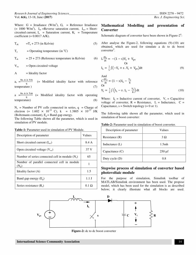
Schematic diagram of converter have been shown in Figure-24:
After analyse the Figure-2, following equations (9)-(10) are
obtained, which are used for simulate a dc to dc boost
converter5.
L 7879 1 sV V.
Or
I= = #= >?−V + s. V +V.@dt (9)
And
C 7/79 = 1 − sI= −/3
Or
V = #D> I= − s. I= −/3 ! dt (10)
Where: IL = Inductive current of converter, Vc = Capacitive
voltage of converter, R = Resistance, L = Inductance, C =
Capacitance, s = Switch topology (= 0 or 1).
The following table shown all the parameter, which used in
simulation of boost converter:
Table-2: Parameter used in simulation of boost converter.
Description of parameter Values
Resistance (R) 3 Ω
Inductance (L) 1.5mh
Capacitance (C) 250 µf
Duty cycle (D) 0.8
Stepwise process of simulation of converter based
photovoltaic module
For the purpose of simulation, Simulink toolbar of
MATLAB/Simulink environment has been used. The propose
model, which has been used for the simulation is as described
below; it clearly illustrate what all blocks are used.
C R
D
s Vc
L
Vpv
IL
Figure-2: dc to dc boost converter
Research Journal of Engineering Sciences________________________________________________________ ISSN 2278 – 9472
Vol. 6(6), 13-18, June (2017) Res. J. Engineering Sci.
International Science Community Association 15
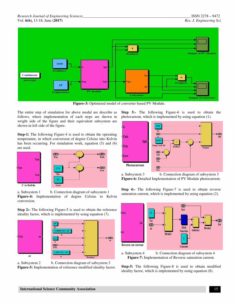
Figure-3: Optimized model of converter based PV Module.
The entire step of simulation for above modal are describe as
follows, where implementation of each steps are shown in
wright side of the figure and their equivalent subsystem are
shown in left side of the figure.
Step-1: The following Figure-4 is used to obtain the operating
temperature, in which conversion of degree Celsius into Kelvin
has been occurring. For simulation work, equation (5) and (6)
are used.
a. Subsystem 1 b. Connection diagram of subsystem 1
Figure-4: Implementation of degree Celsius to Kelvin
conversion.
Step 2:- The following Figure-5 is used to obtain the reference
ideality factor, which is implemented by using equation (7).
a. Subsystem 2 b. Connection diagram of subsystem 2
Figure-5: Implementation of reference modified ideality factor.
Step 3:- The following Figure-6 is used to obtain the
photocurrent, which is implemented by using equation (1).
a. Subsystem 3 b. Connection diagram of subsystem 3
Figure-6: Detailed Implementation of PV Module photocurrent.
Step 4:- The following Figure-7 is used to obtain reverse
saturation current, which is implemented by using equation (2).
a. Subsystem 4 b. Connection diagram of subsystem 4
Figure-7: Implementation of Reverse saturation current.
Step-5: The following Figure-8 is used to obtain modified
ideality factor, which is implemented by using equation (8).
Research Journal of Engineering Sciences________________________________________________________ ISSN 2278 – 9472
Vol. 6(6), 13-18, June (2017) Res. J. Engineering Sci.
International Science Community Association 16
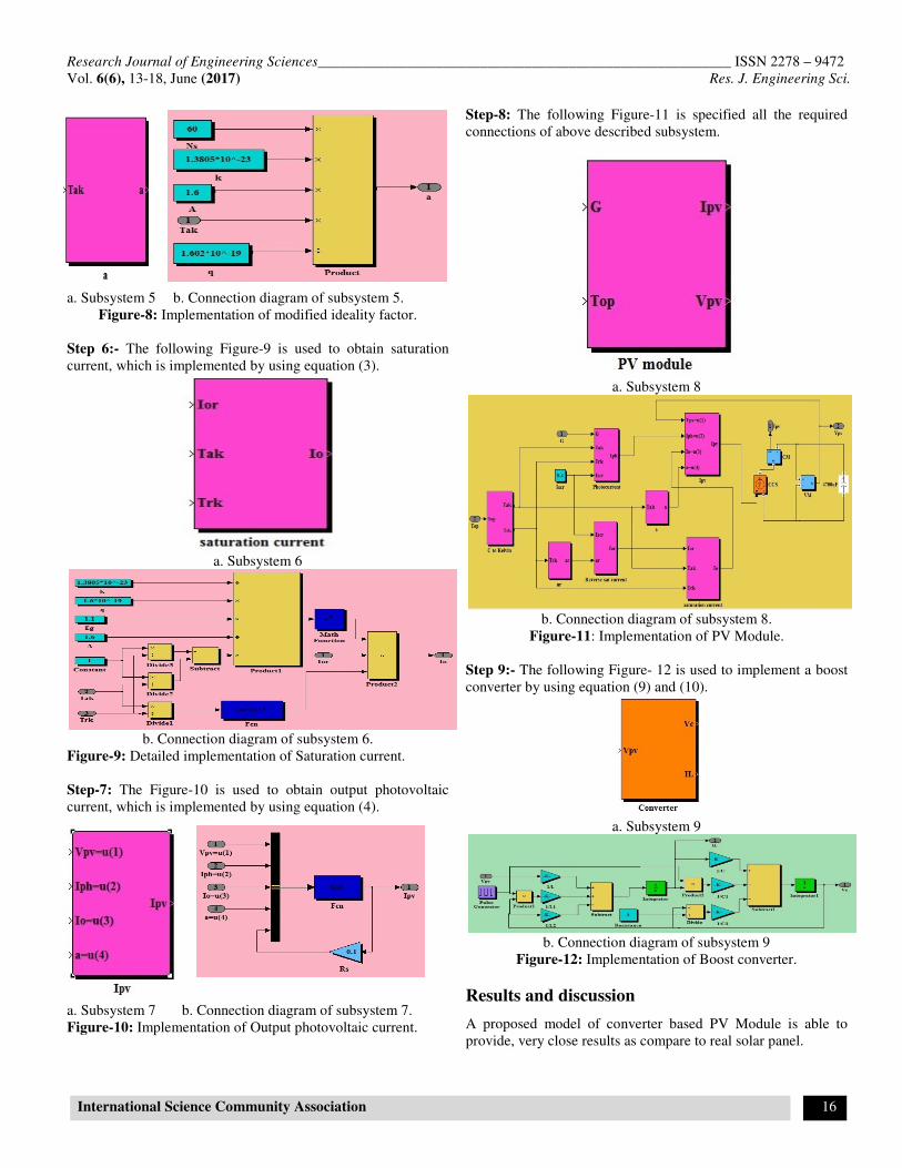
a. Subsystem 5 b. Connection diagram of subsystem 5.
Figure-8: Implementation of modified ideality factor.
Step 6:- The following Figure-9 is used to obtain saturation
current, which is implemented by using equation (3).
a. Subsystem 6
b. Connection diagram of subsystem 6.
Figure-9: Detailed implementation of Saturation current.
Step-7: The Figure-10 is used to obtain output photovoltaic
current, which is implemented by using equation (4).
a. Subsystem 7 b. Connection diagram of subsystem 7.
Figure-10: Implementation of Output photovoltaic current.
Step-8: The following Figure-11 is specified all the required
connections of above described subsystem.
a. Subsystem 8
b. Connection diagram of subsystem 8.
Figure-11: Implementation of PV Module.
Step 9:- The following Figure- 12 is used to implement a boost
converter by using equation (9) and (10).
a. Subsystem 9
b. Connection diagram of subsystem 9
Figure-12: Implementation of Boost converter.
Results and discussion
A proposed model of converter based PV Module is able to
provide, very close results as compare to real solar panel.
Research Journal of Engineering Sciences________________________________________________________ ISSN 2278 – 9472
Vol. 6(6), 13-18, June (2017) Res. J. Engineering Sci.
International Science Community Association 17
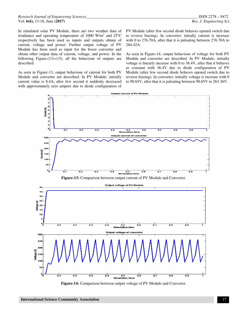
In simulated solar PV Module, there are two weather data of
irradiance and operating temperature of 1000 W/m2 and 25
oC
respectively has been used as inputs and outputs obtain of
current, voltage and power. Further output voltage of PV
Module has been used as input for the boost converter and
obtain other output data of current, voltage, and power. In the
following Figure-(13)-(15), all the behaviour of outputs are
described.
As seen in Figure-13, output behaviour of current for both PV
Module and converter are described. In PV Module; initially
current value is 8.4A, after few second it suddenly decreased
with approximately zero ampere due to diode configuration of
PV Module (after few second diode behaves opened switch due
to reverse biasing). In converter; initially current is increase
with 0 to 276.70A, after that it is pulsating between 276.70A to
284.42A.
As seen in Figure-14, output behaviour of voltage for both PV
Module and converter are described. In PV Module; initially
voltage is linearly increase with 0 to 36.4V, after that it behaves
as constant with 36.4V due to diode configuration of PV
Module (after few second diode behaves opened switch due to
reverse biasing). In converter; initially voltage is increase with 0
to 90.65V, after that it is pulsating between 90.65V to 263.36V.
Figure-13: Comparison between output current of PV Module and Converter.
Figure-14: Comparison between output voltage of PV Module and Converter.
Research Journal of Engineering Sciences________________________________________________________ ISSN 2278 – 9472
Vol. 6(6), 13-18, June (2017) Res. J. Engineering Sci.
International Science Community Association 18
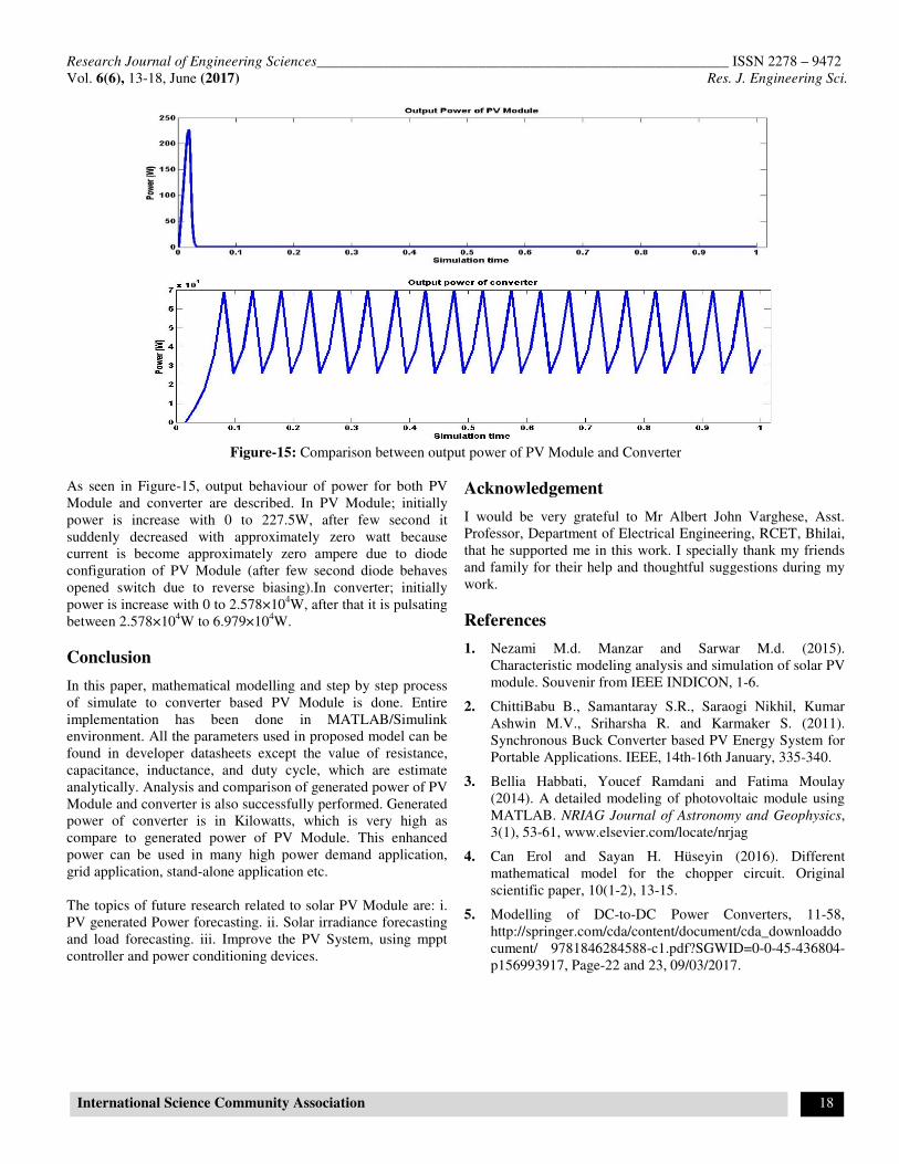
Figure-15: Comparison between output power of PV Module and Converter
As seen in Figure-15, output behaviour of power for both PV
Module and converter are described. In PV Module; initially
power is increase with 0 to 227.5W, after few second it
suddenly decreased with approximately zero watt because
current is become approximately zero ampere due to diode
configuration of PV Module (after few second diode behaves
opened switch due to reverse biasing).In converter; initially
power is increase with 0 to 2.578×10⁴W, after that it is pulsating
between 2.578×10⁴W to 6.979×10
4W.
Conclusion
In this paper, mathematical modelling and step by step process
of simulate to converter based PV Module is done. Entire
implementation has been done in MATLAB/Simulink
environment. All the parameters used in proposed model can be
found in developer datasheets except the value of resistance,
capacitance, inductance, and duty cycle, which are estimate
analytically. Analysis and comparison of generated power of PV
Module and converter is also successfully performed. Generated
power of converter is in Kilowatts, which is very high as
compare to generated power of PV Module. This enhanced
power can be used in many high power demand application,
grid application, stand-alone application etc.
The topics of future research related to solar PV Module are: i.
PV generated Power forecasting. ii. Solar irradiance forecasting
and load forecasting. iii. Improve the PV System, using mppt
controller and power conditioning devices.
Acknowledgement
I would be very grateful to Mr Albert John Varghese, Asst.
Professor, Department of Electrical Engineering, RCET, Bhilai,
that he supported me in this work. I specially thank my friends
and family for their help and thoughtful suggestions during my
work.
References
1. Nezami M.d. Manzar and Sarwar M.d. (2015).
Characteristic modeling analysis and simulation of solar PV
module. Souvenir from IEEE INDICON, 1-6.
2. ChittiBabu B., Samantaray S.R., Saraogi Nikhil, Kumar
Ashwin M.V., Sriharsha R. and Karmaker S. (2011).
Synchronous Buck Converter based PV Energy System for
Portable Applications. IEEE, 14th-16th January, 335-340.
3. Bellia Habbati, Youcef Ramdani and Fatima Moulay
(2014). A detailed modeling of photovoltaic module using
MATLAB. NRIAG Journal of Astronomy and Geophysics,
3(1), 53-61, www.elsevier.com/locate/nrjag
4. Can Erol and Sayan H. Hüseyin (2016). Different
mathematical model for the chopper circuit. Original
scientific paper, 10(1-2), 13-15.
5. Modelling of DC-to-DC Power Converters, 11-58,
http://springer.com/cda/content/document/cda_downloaddo
cument/ 9781846284588-c1.pdf?SGWID=0-0-45-436804-
p156993917, Page-22 and 23, 09/03/2017.