comparison of energy consumption in desalination by
TRANSCRIPT
Contents lists available at ScienceDirect
Desalination
journal homepage: www.elsevier.com/locate/desal
Comparison of energy consumption in desalination by capacitivedeionization and reverse osmosis
Mohan Qina,b,1, Akshay Deshmukha,b,1, Razi Epszteina,b, Sohum K. Patela,b,Oluwaseye M. Owosenib,c, W. Shane Walkerb,c, Menachem Elimelecha,b,⁎
a Department of Chemical and Environmental Engineering, Yale University, New Haven, CT 06520-8286, United StatesbNanosystems Engineering Research Center for Nanotechnology-Enabled Water Treatment (NEWT), Yale University, United Statesc Department of Civil Engineering, The University of Texas at El Paso, El Paso, TX 79968-0513, United States
G R A P H I C A L A B S T R A C T
A B S T R A C T
Capacitive deionization (CDI), which is based on the electrosorption of ions by porous electrodes, is an emerging technology for brackish water desalination.Understanding the key drivers of energy consumption in CDI and benchmarking CDI with reverse osmosis (RO), the current state-of-the-art for brackish and seawaterdesalination, is crucial to guide the future development of desalination technologies. In this study, we develop system-scale models to analyze the energy con-sumption and energy efficiency of CDI and RO over a wide range of material properties and operating conditions. Using our models, we explore how the energeticperformance of CDI and RO compare as a function of feed salinity, water recovery, salt rejection, and average water flux, which is normalized by electrode andmembrane area in CDI and RO, respectively. Our analysis shows that RO is significantly more energy efficient than CDI, particularly when targeting higher salinityfeed streams and higher salt rejection values. For brackish water with a salt concentration of 2000mg L−1, achieving 50% water recovery and 75% salt rejection,with an average water flux of 10 Lm−2 h−1 using CDI requires a specific energy consumption of 0.85 kWhm−3, more than eight times that of RO (0.09 kWhm−3).Importantly, our results also indicate that current efforts to improve electrode materials can only marginally reduce the energy consumption of CDI. We concludewith a discussion highlighting other important factors, such as capital cost, electrode stability, and membrane fouling, which affect the efficacy of CDI and RO forlow-salinity desalination.
https://doi.org/10.1016/j.desal.2019.01.003Received 20 November 2018; Received in revised form 3 January 2019; Accepted 3 January 2019
⁎ Corresponding author at: Department of Chemical and Environmental Engineering, Yale University, New Haven, CT 06520-8286, United States.E-mail address: [email protected] (M. Elimelech).
1 These authors contributed equally to this work.
Desalination 455 (2019) 100–114
Available online 18 January 20190011-9164/ © 2019 Elsevier B.V. All rights reserved.
T

1. Introduction
Currently affecting around 2.8 billion people for at least one montheach year, global water stress levels are projected to increase in thecoming decades, exacerbated by rapid industrialization and populationgrowth [1–3]. Hence, the need for desalination, the process by whichsalt is removed from saline water to generate fresh water, is paramount[2,4,5]. Globally, desalination capacity has tripled since 2000, alle-viating water scarcity by augmenting natural freshwater supplies pro-vided by the hydrological cycle [6].
Desalination processes are primarily classified according to thedriving force applied to achieve water-salt separation [7–11]. Typically,the separation of pure water from a saline solution is driven by eitherthermal-, pressure-, or electrochemical-based chemical potential gra-dient. Despite major technological improvements over the last fivedecades, energy consumption remains a major component of the op-eration cost of desalination facilities. Consequently, the drive to in-crease energy efficiency has facilitated both the gradual improvementof existing processes and the development of new technologies[4,12,13].
The minimum specific energy consumption (SEmin) of a desalinationprocess is defined as the specific energy consumption of a thermo-dynamically reversible process operating with the same feed, brine, andproduct streams. SEmin depends on the feed salinity, water recoveryratio, and salt rejection of a desalination process. For example, the SEmin
for desalination of seawater with 50% water recovery and complete saltrejection is around 1.1 kWh per cubic meter of water produced [4,14].Practical desalination systems, however, incur irreversible entropiclosses either to provide a finite driving force for mass transfer, toachieve a non-zero water flux, or to overcome parasitic losses such asthose caused by frictional forces in flow channels and other processequipment [14,15]. Consequently, the energy consumption of practicaldesalination systems always exceeds SEmin. The energy efficiency of adesalination process is defined as SEmin divided by its actual specificenergy consumption (SE).
Reverse osmosis (RO) is a pressure-driven process that accounts forthe majority of seawater and brackish water desalination capacity dueto its relatively low energy consumption [4,9,16]. In RO, the saline feedwater is pressurized and forced through a semi-permeable thin-filmcomposite (TFC) membrane, resulting in salt-free product water, com-monly termed the permeate, and waste brine, termed the retentate. Theprocess inherently requires the application of a feed pressure that ex-ceeds the osmotic pressure of the exit brine [17,18]. Much research hasaimed to reduce the energy consumption of RO by designing newmembrane materials with increased water permeability. However, re-cent studies have demonstrated the negligible effects of further im-provements in permeability and instead emphasized the need to im-prove membrane water-salt selectivity [19–23].
Capacitive deionization (CDI) is an electrically-driven desalinationtechnology that extracts ions from saline water through the applicationof electric potential (usually< 1.2 V) across two conductive porouselectrodes. Though first proposed in the 1960s [24], CDI has gainedsignificant attention over the last decade as a potential method forbrackish water desalination [25–29]. In the most common CDI config-uration, the saline feed water travels between two oppositely chargedelectrodes. The applied potential difference generates an electric fieldthat causes the ions to migrate towards the porous electrodes and ad-sorb into the electrical double layer (EDL). The adsorbed ions are re-leased into a waste brine stream, regenerating the electrodes for thenext adsorption cycle either by short circuiting the system or by re-versing the applied voltage. Recently, ion-exchange membranes (IEM)have been added in front of the electrodes, preventing the adsorption ofco-ions (i.e., ions of the same charge as the electrode) [30]. Thismembrane CDI process, often referred to as MCDI, exhibits greaterdesalination capacity and charge efficiency compared to the conven-tional configuration [31–34]. A CDI cell can either be operated under
constant-voltage or constant-current mode. Although there is no con-clusive study determining which operation mode is more energy effi-cient, constant-current CDI is often advantageous due to its ability togenerate constant effluent concentration [35–37].
To compete with the energetic performance of RO, research hasmostly focused on the development of new electrode materials for CDI,seeking improved capacitance and conductivity [38–42]. However, dueto the fundamental differences of the two processes, a fair comparisonbetween the energetic demand of RO and CDI has not yet been de-monstrated. Thus, unsubstantiated and controversial conclusions re-garding the energetics of the two processes are often derived. For ex-ample, numerous studies have shown that CDI consumes less than the1.0 kWhm−3 [43,44] required by some existing brackish water RO(BWRO) desalination systems [45,46]. Specifically, it was suggestedthat CDI is more energy efficient than RO when the feed salinity islower than 3.5 g L−1 and the product water salinity is 1 g L−1 [47].However, concluding that CDI is more energy efficient than RO basedon these studies is erroneous, as the energy consumption for RO wasderived from several existing large-scale systems and compared to theenergy consumption of bench-scale CDI modules [45,47,48]. Further-more, the comparison between the energetic demand of CDI and RO inthese studies was not based on the same desalination performance (e.g.,water recovery ratio and salt rejection).
This study aims to systematically compare the energy consumptionin CDI and RO under a wide range of operating conditions to evaluate ifCDI is a feasible alternative to RO for low-salinity water desalination.First, a mathematical model for constant-current CDI is developed tostudy the effect of key parameters, including charging current, salt re-jection, and average water flux, on the energetic performance of CDI.Then the energy consumption and energy efficiency of CDI and RO forbrackish water desalination are compared for a specified feed salinity,water recovery, salt rejection, and average water flux (normalized byunit projected electrode or membrane area for CDI and RO, respec-tively). We conclude by expanding the comparison of CDI with RO toother practical considerations, such as electrode stability and capitalcost.
2. CDI process model and calculation of energy consumption
2.1. CDI process and operation
This modeling study focuses on a multi-cell CDI stack. The cells areconnected in parallel with respect to both electrical and fluid flow. Eachcell consists of a pair of current collectors and porous electrodes. Thepositively charged electrode is equipped with an anion-exchangemembrane (AEM), whereas the negatively charged electrode uses acation-exchange membrane (CEM). Note that this CDI configuration isreferred to as membrane capacitive deionization (MCDI) [32], and isoften employed to improve charge efficiency. Sodium chloride (NaCl)solution, in concentrations representative of brackish water, is used asthe feed. When NaCl solution is fed between the electrodes and anelectric potential applied, sodium ions are transported through the CEMand adsorbed onto the negative electrode. Conversely, chloride ions aretransported through the AEM and adsorbed onto the positive electrode(Fig. 1A). A constant current is applied via a power supply unit and thevoltage throughout the charging cycle is prevented from exceeding1.5 V to ensure that Faradaic reactions (i.e., charge-transfer reactionsoccurring at the surface of the electrode) do not occur. During thedischarge phase, the electrodes are short-circuited while feed solutioncontinues to flow through the channel. The ions accumulated in theelectrodes during the charging step are released into the flow spacerchannel, forming the brine and regenerating the porous electrodes forthe next cycle of salt adsorption (Fig. 1B). To alter the water recoveryratio, the duration of the discharging-step is varied, while holding theflow rate of both steps constant.
M. Qin et al. Desalination 455 (2019) 100–114
101

2.2. Circuit model for CDI
A Simplified Randles Circuit model is applied to characterize theCDI system (Fig. 2A and B). This allows us to investigate the chargingdynamics and energy consumption of CDI. The model consists of a ca-pacitor, C, connected in parallel with a resistor, R2. Here, C is the totalelectrical double layer capacitance for salt adsorption and R2 representsthe polarization and diffusion resistance inside the electrode pores. Thiscapacitor-resistor complex is connected in series to a second resistor,R1, which encompasses the resistance of all other components in thecircuit: membrane resistance, solution resistance, and contact re-sistance between the current collector and the electrode (Fig. 2C).
The Randles circuit is one of the most widely utilized cell models forsupercapacitors [49–53] and serves as a basis for more complex models(e.g., transmission line models) [54–56]. Though relatively simple, theRandles model is a valuable tool for describing the charging and dis-charging processes in CDI, which are similar to supercapacitors. Weassume that the capacitance and the resistance R2 remain the sameduring the charging and discharging processes [57,58], while R1 varies
with the feed solution conductivity (a parameter strongly related to thesalinity of the feedwater). We also assume that sodium and chlorideions have the same adsorption capacity in the porous electrodes, al-lowing for the use of one capacitor in the circuit.
During the charging step, the voltage, V, and current in the differentcomponents, I1, I2, and I3, are calculated as
⎜ ⎟= + = + − ⎛⎝
− ⎞⎠
V I R I R I R R I R tR C
( ) exp2 2 1 1 1 1 2 1 22 (1)
= +R s lGAe
1 (2)
⎜ ⎟= ⎛⎝
− ⎞⎠
I I tR C
exp3 12 (3)
⎜ ⎟= ⎡⎣⎢
− ⎛⎝
− ⎞⎠
⎤⎦⎥
I I tR C
1 exp2 12 (4)
where V is the voltage; I1, I2, and I3 are the currents for R1, R2, and C in
Fig. 1. Schematics of membrane capacitive deioni-zation (MCDI) showing (A) the charging step and (B)the discharging step. When brackish water is fed intothe cell and an external voltage is applied, cationsmigrate through the cation-exchange membrane(CEM) and adsorb on the negative electrode, whileanions migrate through the anion-exchange mem-brane (AEM) and adsorb on the positive electrode.During the discharging step, the power supply isdisengaged, and the electrodes are short-circuited.The ions stored in the electrodes are released intothe flow channel, forming a brine and regeneratingthe porous electrodes for the next cycle of salt ad-sorption.
Fig. 2. Circuit model for CDI. (A) Simplified Randlescircuit for CDI charging step. During the chargingstep, constant current is applied (in the direction ofthe gold arrow) from a power supply device and saltis adsorbed at the electrodes. R1 represents the sumof membrane resistance, solution resistance, andcontact resistance between the current collector andthe electrode; R2 is the polarization resistance anddiffusion resistance inside the electrode pores; and Cis the double layer capacitance of the electrodes. I1,I2, and I3 are the currents through R1, R2, and C,respectively. I1 is equal to the applied current duringthe constant-current charging step. (B) Analoguecircuit for CDI discharging step with short-circuitedelectrodes. Here, the ions stored in the capacitor arereleased and a current opposite in direction to thecharging step (gold arrow) is generated. The vol-tage, Vdischarging, generated from the capacitor, C, isconnected in parallel to R2 during the dischargingstep. (C) Analogy of Randles circuit to the CDI cell:R2 and C represent the resistance and capacitance ofthe electrodes, respectively, while R1 represents theresistance of other CDI components (ion-exchangemembrane resistances, solution resistance, andcontact resistance between the current collector andthe electrode).
M. Qin et al. Desalination 455 (2019) 100–114
102

the system (Fig. 2), respectively; R1 is the sum of membrane resistance,solution resistance, and contact resistance between the current collectorand the electrode; R2 is the polarization resistance and diffusion re-sistance inside the electrode pores; C is the electrode double layer ca-pacitance; t is the time component; s is a fixed parameter representingthe membrane resistance and contact resistance between current col-lector and electrode; l is the thickness of flow channel; G is the con-ductivity of the solution; and Ae is the projected electrode area. Theboundary conditions are: (a) at t=0, the voltage across capacitor C is0, and hence, the voltage V is the same as the voltage across R1; and (b)at infinite time, i3=0, and the voltage across capacitor C is equivalentto the voltage across R2. In the model, R1 is a function of the solutionresistance. Though solution resistance increases down the length of theflow channel as ions are electrosorbed, such effects were neglected inthis study as the value of R1 is rather dominated by the internal re-sistances. In contrast, R1 still varies as a function of time, accounting forthe transient effluent solution conductivity prior to reaching steadystate.
The effluent salt concentration, cP, during the charging step is cal-culated using the current, I1, and charge efficiency, Λ:
= − ∆c c ΛI M tv FP F
CDI
1
(5)
where cF is the initial feed salt concentration, F is the Faraday constant,vCDI is the volume of the flow channel, M is the molecular weight of salt(NaCl, 58.44 gmol−1), and Δt is the duration ions remain in the flowchannel. The charge efficiency describes the moles of salt removed permole of electrons transferred between electrodes; in this study, chargeefficiency is a fixed parameter set to 80% during the charging step[36,47,59,60]. Note that the model accounts for the transient effluentconditions during process startup by setting Δt equivalent to the elapsedtime until reaching the hydraulic retention time (at which point steadystate is achieved).
In the discharging step, the electrodes are short-circuited, releasingthe ions stored in the capacitor and generating current in the oppositedirection. The voltage, Vdischarging, is generated from the capacitor C.During the discharging step, R2 is connected in parallel with R1. Thedischarging current Idischarging is calculated as [61].
⎜ ⎟= − ⎛⎝
− ⎞⎠
IV
Rt
R Cexpdischarging
discharging
t t (6)
where Vdischarging is the voltage across capacitor C at the end of thecharging step and Rt is the total resistance in the discharging step(defined below). A negative current indicates that the current flows inthe opposite direction during the discharging step. The discharge effi-ciency is set to 100%, to idealize the conditions for salt release [61].Hence, by substituting I1 with Idischarging, the brine concentration, cB, inthe discharging step can be calculated:
= −∆
c cΛ I M t
v FB Fdischarging discharging
CDI (7)
The total resistance of the discharging step, Rt, is calculated ac-cording to the resistances at the end of the charging step, R1
′ and, R2,which are connected in parallel during the discharging step:
⎜ ⎟= ⎛⎝ ′
+ ⎞⎠
−
RR R1 1
t1 2
1
(8)
R1′ is related to the feed salt concentration during the discharging
step, while R2 is constant (as in the charging step).
2.3. Energy consumption in CDI
Energy consumption is expressed in either joule (J) or kilowatt-hour(kWh), which can be calculated by multiplying the required powerinput by charging time. Normalizing the energy consumption makes it
possible to compare the energetic performance of CDI with that of ROindependent of process configuration and operational settings. Energyconsumption can be presented in different ways, such as energy con-sumed per mole of salt removed or per unit operation time [31,36,43].Although the most widely used metric for normalized energy con-sumption in bench-scale CDI studies is energy consumption per unitmole of salt removed, we choose to use energy consumption per unitvolume of product water (kWhm−3), which allows for a direct com-parison between the energetics of full-scale CDI and RO systems.
The specific energy consumption, SE, is calculated as [35].
∫=SE Aqt
iVdte
charging
t
0
charging
(9)
where i is defined as the applied current during the charging stepnormalized by the projected electrode area (Ae), q is the volumetricflow rate (flow channel volume divided by hydraulic residence time),tcharging is the duration of the charging step. Note that during the char-ging step in constant-current mode, i is fixed while the voltage, V, varieswith time and is calculated by Eq. (1). An additional source of energyconsumption in CDI is the circulation pump. The energy consumption ofthe circulation pump is strongly related to the CDI configuration andoperation conditions. However, as shown in Appendix A.1, the energyconsumption of the pump is negligible compared to the energy con-sumed during charging and discharging steps, and is therefore not in-cluded in our calculation of energy consumption by CDI. The calcula-tion of energy consumption for high water recovery in Section 5.3 isshown in Appendix A.2.
Based on the circuit model, the specific energy consumption can beseparated into energy consumption by R1 (SER1), R2 (SER2), and C (SEC),as follows:
∫=SE Aqt
i R dtRe
charging
t1
2
02
1charging
(10)
∫=SEqt
I R dt1R
charging
t2 0 2
22
charging
(11)
= − −SE SE SE SEC R R1 2 (12)
where SER1 and SER2 are the specific energy consumption values asso-ciated with R1 and R2 during the charging step, respectively, and SECrepresents the energy stored in the capacitor C during the charging stepand consumed in the discharging step.
The energy efficiency, η, is defined as the minimum specific energyconsumption of desalination, SEmin, divided by the actual specific en-ergy consumption, SE [14]:
=η SESE
min(13)
The minimum specific energy required for desalination is a functionof the feed salinity (cF), product water salinity (cP), and water recoveryratio (R) [15,58,62]:
⎜ ⎟ ⎜ ⎟= ⎡⎣⎢
⎛⎝
⎞⎠
− ⎛⎝
⎞⎠
⎤⎦⎥
SE R T cR
cc
c cc
2 ln lnmin gF B
FP
B
P (14)
where Rg is the ideal gas constant, T is the absolute temperature, and cBis the salinity of the brine. Note that the minimum specific energyconsumption is the energy required by a thermodynamically reversibleprocess, which is independent of the process employed. Analyzing theenergy efficiency of a desalination process allows the assessment of theimpact of different materials, technologies, and process configurationson energetic performance independently of feed salinity, water re-covery, and salt rejection (parameters that affect the minimum energyfor separation but do not directly impact process performance).
M. Qin et al. Desalination 455 (2019) 100–114
103

2.4. Calculation of key performance parameters
The water recovery ratio, R, is the ratio of the volume of watertreated during the charging step, vcharging, to the total volume of waterfed during both the charging and discharging steps, vfeed [63]:
=Rv
vcharging
feed (15)
Three recovery ratios typical of CDI systems are applied in this study— 25%, 50%, and 75% [27]. In this study, the water recovery ratio iscontrolled by varying the discharging-step duration, while the flow rateis held constant between both the discharging step and the chargingstep. Hence, charging- to discharging-step duration ratios of 1/3, 1, and3 correspond to the recovery ratios of 25%, 50%, and 75%, respec-tively.
The salt rejection, Rj, is the fraction of salt that is removed duringthe charging step, which can be calculated as
= −R cc
1jP
F (16)
The average water flux, Jw, is defined as the volume of feed (pro-duct) water during the charging step divided by the projected electrodearea, Ae, and the sum of charging time, tcharging, and discharging time,tdischarging:
=+
Jv
A t t( )wcharging
e charging discharging (17)
The salt adsorption capacity, SAC, describes the salt stored in theelectrode for a given charge cycle:
∫= −SACqMm
c c dt( )t
F P0
charging
(18)
where m is the weight of electrodes. Based on literature data, themaximum salt adsorption capacity used in this study is 30mg g−1 (or0.51meq g−1) [39,64,65]. Upon reaching the maximum salt adsorptioncapacity, salt is no longer removed during the charging step. In Section6, the assumption of maximum salt adsorption is relaxed for novelelectrode materials with further improvement. The introduced metrics,such as specific energy consumption, water recovery ratio, and averagewater flux, are used to evaluate the CDI performance. We note thatsome conventional CDI parameters (e.g., average salt adsorption rateand energy consumption per mole of salt removed) are not analyzedindependently in this study, since they cannot be compared with RO.
3. RO process model and calculation of energy consumption
3.1. Alternative RO system design for variable salt rejection
In RO, the saline feed water is pressurized before flowing into amembrane module where it is contacted with a semi-permeable mem-brane [4]. The hydraulic pressure difference across the membrane,which must exceed the osmotic pressure of the feed stream, creates achemical potential driving force for transmembrane water transport.Water travels down its chemical potential gradient from the high-pressure feed-side, through the membrane, and into the low-pressurepermeate side. Dissolved solutes and other contaminants are largelyrejected by the membrane and remain in the feed stream. Water andsolute transport through thin-film composite polyamide membranes,the current state-of-the-art, is governed by the solution-diffusion model[66]. Currently, RO membranes are able to achieve NaCl rejection va-lues in excess of 99.5% [19]. Because CDI cannot achieve high saltrejection [29,43,47,67], to perform a fair comparison between CDI andRO, we focus on low-rejection desalination with NaCl rejection valuesranging from 10% to 90%.
Fig. 3 depicts a novel low-rejection RO system that combines aconventional RO module with product and brine bypass streams that
allows some proportion of the feed stream to circumvent the high-pressure pump and the membrane module. Prior to pressurization, afraction of the feed stream is split off into either the product bypass, αP,or the brine bypass, αB, streams that are pumped directly into theproduct and brine streams, respectively. The remainder of the feedstream, which has a flow rate fraction of αRO=1− αP− αB, is pres-surized using a high-pressure pump before entering a conventional ROmembrane module with a specified module-scale water recovery ratio,r. The permeate from the RO module is mixed with saline water fromthe product bypass stream to form the product stream. Similarly, thebrine from the RO module is mixed into the system-level brine stream.Mechanical energy is recovered from the brine stream as it leaves theRO module by an energy recovery device, such as a pressure exchangeror a turbine. In this analysis, it is assumed that salt passage through theRO membrane is negligible. This assumption is broadly valid whendiscussing a system-scale salt rejection of< 90% as most RO mem-branes are designed to achieve a NaCl rejection of> 99%. In this sce-nario, the system-scale salt rejection is primarily determined by theflow rate fraction of the product bypass stream rather than the module-scale rejection of the RO membrane module.
The module-scale water recovery and flow rate fractions of theproduct and brine bypass streams can be adjusted to achieve a specifiedsystem-scale water recovery and salt rejection. By performing massbalances on water and salt, the flow rate fraction of the product bypassstream, αP, for the low-rejection RO system shown in Fig. 3 may beexpressed as a function of the system-scale recovery ratio, R=QP/QF,and the salt rejection, Rj=1− (cP/cB):
=−
−α
R RRR
(1 )1P
j
j (19)
where QF and QP are the volumetric flow rates of the feed and permeatestreams, respectively.
Similarly, by performing a mass balance on the water on the pro-duct-side of the system, we may determine the flow rate fraction of theRO feed stream, αRO, which is inversely proportional to the module-scale water recovery, r, for a given system-scale recovery and rejection:
⎜ ⎟= ⎛⎝
−−
⎞⎠
αRR
rR
RR1
1ROj
j (20)
Eqs. (19) and (20) show that as Rj→ 0, the zero-rejection case, αP→R and αRO→ 0, signifying that the feed stream is simply split into twostreams without any water-salt separation. Similarly, in the perfectsystem-scale salt rejection scenario, as Rj→ 1, Eq. (19) shows that thelow-rejection process simplifies to a conventional RO desalinationsystem with a brine bypass stream only since αP→ 0.
3.2. Energy consumption in low-rejection RO
In most RO systems, the primary source of energy consumption is ahigh-pressure pump, which is required to pressurize the feed streamand drive transmembrane water flux. The specific energy consumptionof the single-stage low-rejection RO system shown in Fig. 3, SERO, isgiven by [14]:
=− −
SEα η r P
η R[1 (1 )]Δ
RORO ERD
P (21)
where ΔP represents the transmembrane hydraulic pressure, while ηPand ηERD denote the efficiency of the high-pressure pump and the en-ergy recovery device, respectively. In this analysis, ηP and ηERD are bothfixed at 80% throughout [14]. It is important to note that both αRO andΔP are functions of the module-scale water recovery, r. Increasing rsimultaneously leads to a reduction in αRO and an increase in ΔP.Lowering αRO leads to a reduction in SERO by lowering the volumetricflow rate through the high-pressure pump, while raising ΔP leads to anincrease in SERO by raising the hydraulic pressure at which the pump
M. Qin et al. Desalination 455 (2019) 100–114
104

must operate. Consequently, module-scale water recovery must be op-timized to minimize the specific energy consumption of the system,while achieving the required system-scale recovery and rejection, R andRj, respectively. Further details on the optimization of Eq. (21) areprovided in Appendix C.
Throughout our analysis, we determine SERO by calculating thetransmembrane hydraulic pressure, ΔP, required to achieve a givenaverage water flux, Jw, for a specified system-scale water recovery andsalt rejection, R and Rj, respectively. Specifying the water recovery andsalt rejection of a desalination system fixes the extent of separation,while specifying the average water flux fixes the kinetic efficiency ofthe process, a measure of the amount of mass transfer area required perunit of water production. The ΔP required to achieve a specified r, R, Rj,and Jw values, is determined using a one-dimensional finite elementmodel to integrate the key transmembrane mass transfer equationswhile accounting for variations in flow rate and salt concentrationalong the membrane module.
In our module-scale model, the local water flux, Jw, across an in-finitesimal membrane element is expressed as [19]:
= −J A ΔP π c( ( ))w F m, (22)
where A represents the water permeability coefficient of the membrane,cF, m represents the salt concentration at the feed-side membrane-so-lution interface, and π represents the osmotic pressure as a function ofsalt concentration. Increasing the water permeability coefficient re-duces the mass transfer resistance of the membrane, leading to a re-duction in the required transmembrane hydraulic pressure. In thisstudy, an A value of 5 L m−2 h−1 bar−1 is assumed, which is typical forcommercial brackish water RO membranes [19,66,68].
The impact of concentration polarization is incorporated using thefilm model to express the salt concentration at the membrane-solutioninterface in terms of the bulk feed-side salt concertation, cF, b [69]:
⎜ ⎟= ⎛⎝
⎞⎠
c c Jk
expF m F bw
F, ,
(23)
where kF is the feed-side mass transfer coefficient. The feed-side masstransfer coefficient is a function of the hydrodynamic conditions in thefeed channel and can be increased by increasing the cross-flow velocityor improving spacer design to enhance mixing in the membrane
channel. In this analysis, we assume a kF value of 150 L m−2 h−1, whichis typical for current RO systems [19]. Further details on the module-scale modeling performed are provided in Appendix C.
4. Model prediction of CDI performance
4.1. CDI performance for different currents
To evaluate the developed CDI model, the effect of key parameters(e.g., current, salt rejection, and average water flux) on the energeticperformance of CDI was investigated. The CDI stack and reactor con-figuration parameters are described in Table 1, while the specifiedcircuit parameters are given in Table 2. The CDI stack consists ofmultiple cells with a total volume of 0.02 L, and the thickness of eachchannel is set to 0.10mm. The electrode area density is 89 gm−2 with amaximum salt adsorption capacity of 0.51meq g−1 (Table 1). For thecircuit parameters, we use relatively high electrical double layer ca-pacitance (60 F g−1), low internal resistance (1.8Ωm−2), and lowelectrode resistance (7.1Ωm−2) compared to typical values (Table 2)[56,70]. The same set of circuit parameters, which are theoreticallydependent only on the material properties of the CDI stack (and not onthe operating conditions), will be applied for the CDI modeling in theremainder of the study. Additionally, no Faradaic reactions in theelectrodes were considered throughout this study, further idealizing theperformance.
The effect of current on the applied voltage and effluent con-centration was investigated with fixed charging-step duration (300 s)and average water flux (10 Lm−2 h−1). A constant current (from anexternal power supply) was applied during the charging step, followedby a discharging step of the same duration (i.e., 50% water recovery) atzero external applied cell voltage. When the current in the charging step(normalized by projected electrode area) was changed from 5 Am−2 to20 Am−2, the maximum voltage at the end of charging step increasedfrom 0.32 V to 1.3 V (Fig. 4A). Following an initial rapid increase due tothe membrane, solution, and contact resistances, the cell voltage stea-dily increased during the charging step. The voltage at the end of thecharging cycle was limited to 1.5 V to prevent Faradic reactions. After abrief initial transition period, the voltage continued to increase whilethe effluent salt concentration remained constant throughout the 300 scharging step (Fig. 4B). During the discharging step, the effluent salt
Feed
Electrical Energy Input
Energy Recovery
Device
Brine
Product
High Pressure
Pump
Product Bypass (flow rate fraction: )
Module-scale water recovery:
System-scale water recovery:
Brine Bypass (flow rate fraction: )
Average water flux:
Fig. 3. Schematic depicting a novel low-rejectionreverse osmosis system with energy recovery. Salinefeed stream is pressurized using energy provided byan electrically powered pump before entering themembrane module. The salt rejection of the overallsystem is controlled using a product bypass throughwhich a proportion of the feed stream, αP, is pumpeddirectly into the product stream without passingthrough the RO membrane module. A brine bypassstream, through which a fraction of the feed stream,αB, is pumped directly into the brine stream, is usedto reduce the energy consumption of the system byreducing the flow rate through the high-pressurepump. Mechanical energy is recovered from thepressurized brine stream as it leaves the membranemodule using an energy recovery device, such as apressure exchanger or a turbine.
Table 1Specified parameters for CDI reactor configuration based on values described inprevious studies [39,43,47,64,65,71,72].
Parameter Value
Electrode area density, m/Ae (gm−2) 89Maximum salt adsorption capacity, SAC (meq g−1) 0.51Reactor volume, vCDI (L) 0.02Spacer thickness, l (mm) 0.10
Table 2Specified parameters for the CDI circuit model based on commonvalues in CDI literature [56,70].
Parameter Value
Capacitance, C (F g−1) 60Internal resistance, s/Ae (Ωm−2) 1.8Electrode resistance, R2/Ae (Ωm−2) 7.1
M. Qin et al. Desalination 455 (2019) 100–114
105

concentration rises rapidly before reaching a peak value and decreasingback to the initial feed concentration. The area under the curve inFig. 4B (shaded area) indicates that 96.8% of the salt can be desorbedinto the brine with a current of 5 Am−2, which is representative ofexcellent electrode regeneration. Therefore, we exclude the effect ofelectrode instability for 50% water recovery in this study.
The model confirmed that the applied current in the charging stepstrongly affects the energy consumption and salt rejection. The specificenergy consumption was 0.06, 0.52, and 0.91 kWhm−3 for appliedcurrent of 5, 15, and 20 Am−2, respectively (Fig. 4C). Note that therelative energetic contribution of each component in the circuit model(49.1 ± 0.2%, 16.4 ± 0.1%, and 34.4 ± 0.2% for R1, R2, and C, re-spectively) is independent of the applied current. This indicates that theresistances due to membrane, feed solution, and contact between cur-rent collector and electrode are a key issue for CDI systems, as discussedbefore [56]. Theoretically, some of the energy consumed by the capa-citor, C, which is about one third of the total specific energy con-sumption, can be recovered during the discharging step, as we furtherdiscuss in Section 5.4.
The effect of applied current on salt rejection was demonstrated byan increase of salt rejection from 21% to 82% with increasing currentfrom 5 Am−2 to 20 Am−2 (Fig. 4D). Using a higher current also leadsto a slightly higher energy efficiency. For example, the energy effi-ciency is 4.1% for a current of 20 Am−2, compared to 3.5% for acurrent of 5 Am−2.
4.2. CDI performance for different salt rejections and average water fluxes
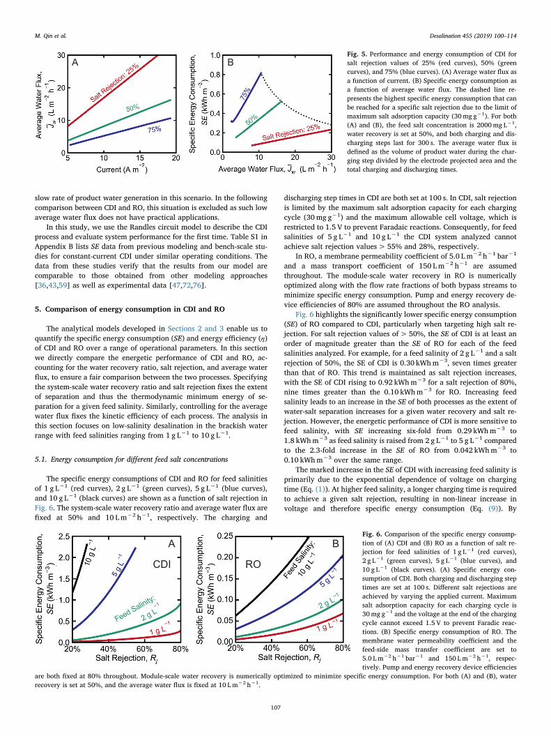
Salt rejection is a key metric used to evaluate the performance ofvarious desalination processes, including CDI [73–75]. In Fig. 5A weshow the relationship between average water flux and applied currentfor salt rejections of 25%, 50%, and 75% (as determined through the
model). The average water flux depends linearly on the applied currentduring the charging step to achieve a specific salt rejection. With thesame current, a higher average water flux led to a lower salt rejection(Fig. 5A). For example, when the applied current is 10 Am−2, theaverage water flux is 16.9, 8.1, and 5.3 Lm−2 h−1 for salt rejections of25%, 50%, and 75%, respectively. Both the maximum salt adsorptioncapacity (30mg g−1 or 0.51meq g−1) and the maximum allowablevoltage (1.5 V) could limit the applied current. In this case, the saltadsorption was found to be the limiting parameter, as 30mg g−1 ad-sorption was attained at a voltage of only 1.2 V. Hence, the appliedcurrent could no longer be increased for the remainder of the 300 scharging-step (Fig. S1 in Appendix B).
The specific energy consumption, SE, increases with average waterflux (Fig. 5B). This trend becomes more significant at higher salt re-jection. For instance, at 75% salt rejection, increasing average waterflux from 5.0 to 11 Lm−2 h−1 corresponds to an increase in SE from0.45 to 0.84 kWhm−3. The dashed line represents the highest specificenergy consumption that can be reached for a specific salt rejectionunder the indicated operating conditions due to the limit of maximumsalt adsorption capacity (30mg g−1).
A reduction in the charging-step time typically leads to an increasedaverage water flux, which is directly proportional to electrical currentrequired. For example, when the charging-step time is increased from100 s to 400 s with a fixed salt rejection of 75%, the average water fluxincreases to 20 Lm−2 h−1 (Fig. S2A in Appendix B). An increasedaverage water flux leads to an increase in the SE as the charging-steptime is decreased from 400 s to 100 s. In general, the SE in CDI is shownto decrease as the average water flux is decreased. However, this trendis reversed when the current and average water flux are extremely low.For example, when the average water flux is increased from 6.5 to7.1 Lm−2 h−1 with a charging-step time of 100 s, the SE decreases from0.85 to 0.67 kWhm−3 (Fig. S2B in Appendix B). This results from the
A B
C D
Fig. 4. (A) Cell voltage and (B) ef-fluent salt concentration during thecharging and discharging steps in aCDI process with constant current of5 Am−2 (blue curves), 15 Am−2
(green curves), and 20 Am−2 (greycurves). Negative voltage indicatesthe current flows in the opposite di-rection during the discharging step.The shaded area in (B) represents theamount of salt adsorbed during thecharging step and desorbed duringthe discharging step with a chargingcurrent of 5 Am−2. (C) Specific en-ergy consumption of the CDI compo-nents R1 (red bars), R2 (green bars),and C (light blue bars) according tothe Randles circuit model. R1 re-presents the sum of membrane re-sistance, solution resistance, andcontact resistance between the cur-rent collector and the electrode; R2 isthe polarization resistance and diffu-sion resistance inside the electrodepores; and C is double layer electrodecapacitance (Fig. 2). (D) Salt rejection(red bars) and energy efficiency(green bars) of CDI for three differentcurrents in the charging step. In allthe above model calculations, theaverage water flux is fixed at10 Lm−2 h−1 (based on electrodeprojected area), water recovery is50%, and feed salt concentration is2000mg L−1.
M. Qin et al. Desalination 455 (2019) 100–114
106
slow rate of product water generation in this scenario. In the followingcomparison between CDI and RO, this situation is excluded as such lowaverage water flux does not have practical applications.
In this study, we use the Randles circuit model to describe the CDIprocess and evaluate system performance for the first time. Table S1 inAppendix B lists SE data from previous modeling and bench-scale stu-dies for constant-current CDI under similar operating conditions. Thedata from these studies verify that the results from our model arecomparable to those obtained from other modeling approaches[36,43,59] as well as experimental data [47,72,76].
5. Comparison of energy consumption in CDI and RO
The analytical models developed in Sections 2 and 3 enable us toquantify the specific energy consumption (SE) and energy efficiency (η)of CDI and RO over a range of operational parameters. In this sectionwe directly compare the energetic performance of CDI and RO, ac-counting for the water recovery ratio, salt rejection, and average waterflux, to ensure a fair comparison between the two processes. Specifyingthe system-scale water recovery ratio and salt rejection fixes the extentof separation and thus the thermodynamic minimum energy of se-paration for a given feed salinity. Similarly, controlling for the averagewater flux fixes the kinetic efficiency of each process. The analysis inthis section focuses on low-salinity desalination in the brackish waterrange with feed salinities ranging from 1 g L−1 to 10 g L−1.
5.1. Energy consumption for different feed salt concentrations
The specific energy consumptions of CDI and RO for feed salinitiesof 1 g L−1 (red curves), 2 g L−1 (green curves), 5 g L−1 (blue curves),and 10 g L−1 (black curves) are shown as a function of salt rejection inFig. 6. The system-scale water recovery ratio and average water flux arefixed at 50% and 10 Lm−2 h−1, respectively. The charging and
discharging step times in CDI are both set at 100 s. In CDI, salt rejectionis limited by the maximum salt adsorption capacity for each chargingcycle (30mg g−1) and the maximum allowable cell voltage, which isrestricted to 1.5 V to prevent Faradaic reactions. Consequently, for feedsalinities of 5 g L−1 and 10 g L−1 the CDI system analyzed cannotachieve salt rejection values> 55% and 28%, respectively.
In RO, a membrane permeability coefficient of 5.0 L m−2 h−1 bar−1
and a mass transport coefficient of 150 Lm−2 h−1 are assumedthroughout. The module-scale water recovery in RO is numericallyoptimized along with the flow rate fractions of both bypass streams tominimize specific energy consumption. Pump and energy recovery de-vice efficiencies of 80% are assumed throughout the RO analysis.
Fig. 6 highlights the significantly lower specific energy consumption(SE) of RO compared to CDI, particularly when targeting high salt re-jection. For salt rejection values of> 50%, the SE of CDI is at least anorder of magnitude greater than the SE of RO for each of the feedsalinities analyzed. For example, for a feed salinity of 2 g L−1 and a saltrejection of 50%, the SE of CDI is 0.30 kWhm−3, seven times greaterthan that of RO. This trend is maintained as salt rejection increases,with the SE of CDI rising to 0.92 kWhm−3 for a salt rejection of 80%,nine times greater than the 0.10 kWhm−3 for RO. Increasing feedsalinity leads to an increase in the SE of both processes as the extent ofwater-salt separation increases for a given water recovery and salt re-jection. However, the energetic performance of CDI is more sensitive tofeed salinity, with SE increasing six-fold from 0.29 kWhm−3 to1.8 kWhm−3 as feed salinity is raised from 2 g L−1 to 5 g L−1 comparedto the 2.3-fold increase in the SE of RO from 0.042 kWhm−3 to0.10 kWhm−3 over the same range.
The marked increase in the SE of CDI with increasing feed salinity isprimarily due to the exponential dependence of voltage on chargingtime (Eq. (1)). At higher feed salinity, a longer charging time is requiredto achieve a given salt rejection, resulting in non-linear increase involtage and therefore specific energy consumption (Eq. (9)). By
A BFig. 5. Performance and energy consumption of CDI forsalt rejection values of 25% (red curves), 50% (greencurves), and 75% (blue curves). (A) Average water flux asa function of current. (B) Specific energy consumption asa function of average water flux. The dashed line re-presents the highest specific energy consumption that canbe reached for a specific salt rejection due to the limit ofmaximum salt adsorption capacity (30mg g−1). For both(A) and (B), the feed salt concentration is 2000mg L−1,water recovery is set at 50%, and both charging and dis-charging steps last for 300 s. The average water flux isdefined as the volume of product water during the char-ging step divided by the electrode projected area and thetotal charging and discharging times.
A B
CDI RO
Fig. 6. Comparison of the specific energy consump-tion of (A) CDI and (B) RO as a function of salt re-jection for feed salinities of 1 g L−1 (red curves),2 g L−1 (green curves), 5 g L−1 (blue curves), and10 g L−1 (black curves). (A) Specific energy con-sumption of CDI. Both charging and discharging steptimes are set at 100 s. Different salt rejections areachieved by varying the applied current. Maximumsalt adsorption capacity for each charging cycle is30mg g−1 and the voltage at the end of the chargingcycle cannot exceed 1.5 V to prevent Faradic reac-tions. (B) Specific energy consumption of RO. Themembrane water permeability coefficient and thefeed-side mass transfer coefficient are set to5.0 Lm−2 h−1 bar−1 and 150 Lm−2 h−1, respec-tively. Pump and energy recovery device efficiencies
are both fixed at 80% throughout. Module-scale water recovery is numerically optimized to minimize specific energy consumption. For both (A) and (B), waterrecovery is set at 50%, and the average water flux is fixed at 10 Lm−2 h−1.
M. Qin et al. Desalination 455 (2019) 100–114
107

contrast, SE in RO increases almost linearly with feed salinity. For afixed water recovery and salt rejection, the concentration of the brinestream increases linearly with feed salinity leading to an approximatelylinear increase in the osmotic pressure of the brine stream, which de-termines the hydraulic pressure required and thus the SE. The SE ofboth processes is small when salt rejection is low as the extent of water-salt separation is low. For very low rejection values, the feed streampasses through the electrode stacks with minimal salt removal in CDI.Similarly, in the novel RO system modeled, the majority of the feedstream bypasses the membrane module and the high pressure pumpwhen salt rejection is very low.
Although the charge efficiency in CDI varies slightly with increasingcurrent [43], a constant charge efficiency of 80% is applied to simplifythe calculation based on previous studies [36,47,59,60]. Increasing thecharge efficiency to 90% reduces the SE of CDI (Fig. S3 in Appendix B),but not to the extent required for CDI to be energetically competitivewith RO.
5.2. Energy efficiency as a function of average water flux
Energy efficiency and average water flux, a measure of water pro-duction per unit system area or volume, are key performance metricsfor desalination processes [77–79]. For a given water recovery and saltrejection, increasing energy efficiency reduces energy consumption,leading to a reduction in operating costs, whereas increasing averagewater flux reduces system size leading to a reduction in capital costs.Membrane-based desalination systems typically exhibit a trade-off be-tween energy efficiency (η) and average water flux (Jw). For a fixedwater recovery and salt rejection, increasing Jw comes at the expense ofa reduction in η, and vice versa [43,79,80]. This trade-off is a result ofthe energy penalty associated with increasing the mass transport rate ofsalt in CDI and water in RO for a fixed set of electrode and membraneproperties, respectively. Energy efficiency is defined as the thermo-dynamic minimum specific energy consumption, a measure of theuseful work performed by a desalination process, divided by the mod-eled specific energy consumption. Throughout this analysis, averagewater flux is defined as the rate of water production normalized byprojected electrode area for CDI or membrane area for RO.
Fig. 7 shows how the energy efficiency of CDI and RO varies withaverage water flux for salt rejection values of 25% (red curves), 50%(green curves), and 75% (blue curves). The system-scale water recoveryratio and feed salinity are fixed at 50% and 2 g L−1, respectively. In
CDI, both the charging- and discharging-step times, which are equiva-lent throughout, vary from 400 s (the lower boundary of each curve) to100 s (the top boundary of each curve). The maximum salt adsorptioncapacity for each charging cycle is 30mg g−1 in each case. In RO, themembrane permeability coefficient is increased from4.0 Lm−2 h−1 bar−1 to 6.0 Lm−2 h−1 bar−1 going from the lower tothe upper edge of each curve, respectively. The solid lines represent amembrane permeability coefficient is of 5.0 Lm−2 h−1 bar−1. A masstransport coefficient of 150 Lm−2 h−1 is assumed throughout. As be-fore, pump and pressure exchanger efficiencies are both fixed at 80%throughout. The relationship between energy efficiency and averagewater flux with 100% salt rejection is shown for RO (black curve).
Fig. 7 illustrates the distinct trade-off between energy efficiency andaverage water flux evident in both CDI and RO. In each case, increasingthe average water flux leads to a rapid decrease in energy efficiency. InCDI, an increase in water flux necessitates an increase in current densityto accelerate the rate at which salt ions are removed. For a given waterrecovery and salt rejection, this increase in required current results in ahigher specific energy consumption and a lower energy efficiency. Forexample, for a salt rejection of 50%, increasing the average water fluxfrom 5.0 Lm−2 h−1 to 10 Lm−2 h−1 leads to an average 31% reductionin energy efficiency from 5.9% to 4.1%. Increasing the average waterflux further to 20 Lm−2 h−1 causes a further 16% decrease in energyefficiency to 3.1%.
Similarly, in RO, increasing the average water flux requires an in-crease in the transmembrane hydraulic pressure, increasing specificenergy consumption and lowering energy efficiency [14,19]. For a saltrejection of 75%, doubling the average water flux from 5.0 Lm−2 h−1
to 10 Lm−2 h−1 results in a 17% reduction in energy efficiency from25% to 21%. Increasing the average water flux to 20 Lm−2 h−1 inducesa further reduction in energy efficiency to 15%.
Fig. 7 highlights the superior energy efficiency of RO compared toCDI across a wide range of average water flux and salt rejection valuesfor the range of electrode and membrane properties analyzed. The en-ergy efficiency of CDI slightly exceeds that of RO only for average waterfluxes of< 5.0 Lm−2 h−1 in the 25% salt rejection case. However, it isimportant to note that in this low average water flux and low-rejectionscenario, the specific energy consumption of RO is very low (around0.016 kWhm−3 for an average water flux of 5.0 Lm−2 h−1 and a saltrejection of 25%). Hence, small improvements in energy efficiency areof limited practical significance.
For low salt rejection values, the energy efficiency of RO is low as
A B
CDI RO
Fig. 7. Comparison of the energy efficiency of (A)CDI and (B) RO as a function of average water fluxfor salt rejection values of 25% (red curves), 50%(green curves), 75% (blue curves), and 100% (blackcurve). Energy efficiency is defined as the thermo-dynamic minimum specific energy consumption di-vided by the modeled specific energy consumption.The water recovery ratio and feed salt concentrationare fixed at 50% and 2000mg L−1, respectively. (A)Energy efficiency of CDI. Average water flux in CDI isdefined as the flow rate during the charging stepnormalized by electrode projected area and waterrecovery. The energy efficiency of CDI is only weaklydependent on salt rejection, and therefore the curvesrepresenting salt rejection values of 25% and 50%overlap with the 75% salt rejection curve. The band
of energy consumption for each salt rejection is calculated using a wide range of charging-step times, currents, and hydraulic detention times. The charging-step time,which is the same as discharging-step time for 50% water recovery, varied from 400 s (bottom edge) to 100 s (top edge). The maximum salt adsorption capacity foreach charging cycle is 30mg g−1 and the voltage at the end of the charging cycle cannot exceed 1.5 V to prevent Faradic reactions. (B) Energy efficiency of RO.Average water flux is defined as the total transmembrane flow rate divided by the total membrane area. Solid lines represent a membrane water permeabilitycoefficient (A) of 5.0 L m−2 h−1 bar−1. The shaded area represents the range of energy efficiencies attainable as the A value is increased from 4.0 Lm−2 h−1 bar−1
(bottom edge) to 6.0 L m−2 h−1 bar−1 (top edge). The feed-side mass transfer coefficient is 150 Lm−2 h−1 in each case. Pump and energy recovery device efficienciesare both fixed at 80% throughout. Note that the 100% salt rejection curve, which is shown for RO as a reference, cannot be achieved in CDI under the simulatedconditions. Module-scale water recovery is numerically optimized to maximize energy efficiency.
M. Qin et al. Desalination 455 (2019) 100–114
108

the pure permeate water exiting the membrane module is irreversiblymixed with the saline product bypass stream to form the final productwater. In addition, energy efficiency is relatively independent ofaverage water flux in the low salt rejection scenario as the majority ofthe feed streams is pumped directly into the product and brine streams,bypassing the membrane module. In contrast, energy consumption inCDI is directly related to rate of salt removal, which determines theelectrical current required during the charging step. Hence, the energyefficiency of CDI is relatively independent of salt rejection. Due to theweak dependence of energy efficiency on salt rejection, the curves re-presenting salt rejection values of 25%, 50%, and 75% largely overlap.With constant charging-step time, increased salt rejection requiresprolonged hydraulic retention time to facilitate salt ion transport,leading to the low average water flux. For example, the highest averagewater fluxes are 18 and 35 Lm−2 h−1, for 75% and 50% salt rejection,respectively, obtained with 19 s and 9.3 s HRT, respectively.
5.3. Energy efficiency across a range of water recoveries and salt rejectionvalues
The required water recovery ratio and salt rejection of a desalina-tion process depend on a range of case specific factors including thefeed salinity, desired product water salinity, and ease of brine disposal.Fig. 8 illustrates how the energy efficiency of CDI and RO varies acrossa wide range of water recovery ratios and salt rejection values. The feedsalt concentration and average water flux are fixed at 2000mg L−1 and10 Lm−2 h−1, respectively. For CDI, the charging-step time is fixed at300 s, while discharging time decreases from 6000 s (5% water re-covery) to 15 s (95% water recovery). When even faster desorption isrequired, an external reverse current is applied during the dischargingstep to release salt ions prior to the next charging step. The requiredreverse current varies according to the water recovery ratio and saltrejection. Maximum salt adsorption capacity for each charging cycle is30 mg g−1 and the voltage at the end of the charging cycle cannot ex-ceed 1.5 V to prevent Faradic reactions. The hatching at the top left ofFig. 8A indicates the region where the maximum salt adsorption ca-pacity or maximum voltage exceed these limits. The water recovery andsalt rejection values in the blank region at the top right cannot beachieved for the specified average water flux and charging-step time.This is primarily due to the unsteady salt adsorption in the early stagesof the charging cycle and the low conductivity of the product waterwhen salt rejection is high. In RO, a membrane permeability coefficientof 5.0 L m−2 h−1 bar−1 and a mass transport coefficient of
150 Lm−2 h−1 are assumed throughout. The module-scale water re-covery in RO is numerically optimized along with the flow rate frac-tions of both bypass streams to minimize specific energy consumption.Pump and energy recovery device efficiencies of 80% are assumedthroughout the RO analysis.
Fig. 8 further demonstrates the energetic advantages of RO com-pared to CDI, particularly for high salt rejection desalination. For ex-ample, for a water recovery ratio of 50% and a salt rejection of 50% theenergy efficiency of RO is 13%, 4 times greater than the energy effi-ciency of CDI under the same conditions. This difference between theenergetic performance of RO and CDI widens as salt rejection increases,with RO being 14 times more efficient than CDI for a water recoveryand salt rejection of 50% and 80%, respectively. The energy efficiencyof CDI decreases monotonically with increasing salt rejection as theenergy required to remove salt ions from the feed water increases as thecharge that is stored in each electrode increases. In contrast, the energyefficiency of RO increases with salt rejection as the extent of un-controlled mixing that occurs when pure water from the RO membranemodule is mixed with the saline product bypass stream is reduced. Theapplication of an external reverse current, which is required to increasethe rate of salt desorption during the discharge step in CDI to achievehigh recovery ratios, further reduces the energy efficiency of CDI athigh water recovery values. For a water recovery ratio of 80% and a saltrejection of 90%, the energy efficiency of RO is 27%, 50 times greaterthan that of CDI under the same conditions. Fig. 8 shows that CDI ismore energy efficient than RO for salt rejection values of< 25%, par-ticularly when water recovery is high. For example, for a water re-covery of 95% and a salt rejection of 20%, the energy efficiency of CDIis 5.1%, slightly greater than the energy efficiency of RO, which is4.9%. However, as discussed previously, the specific energy consump-tion of RO is very low in the high water recovery, low salt rejectionscenario (around 0.0011 kWhm−3 for a water recovery of 95% and asalt rejection of 20%); hence, small improvements in energy efficiencyare of limited practical significance. In addition, this range of low saltrejection values is of limited practical relevance in most desalinationapplications.
5.4. Will CDI outperform RO with the implementation of energy recovery?
In CDI, electrical energy stored in the electrodes during the chargingstep can potentially be recovered during the discharging step by con-necting an external load between the cathode and anode [81,82]. En-ergy recovered during the discharging step can be used to supply a
A B
CDI RO
Fig. 8. Comparison of the energy efficiency (η) of(A) CDI and (B) RO as a function of water re-covery (R) and salt rejection (Rj). Energy effi-ciency is defined as the thermodynamic minimumspecific energy consumption divided by themodeled specific energy consumption. The feedsalt concentration and average water flux arefixed at 2000mg L−1 and 10 Lm−2 h−1, respec-tively, throughout. Specific energy consumption(SE) values are indicated using an overlaid con-tour map (white curves). (A) Energy efficiency ofCDI. The charging-step time is fixed at 300 s,while discharging time varies from 6000 s (5%water recovery) to 15 s (95% water recovery).Charging and discharging steps have the same
flow rate. When required, an external reverse current is applied during the discharging step to release salt ions prior to the next charging step. The required reversecurrent varies according to the water recovery ratio and salt rejection. Maximum salt adsorption capacity for each charging cycle is 30mg g−1 and the voltage at theend of the charging cycle cannot exceed 1.5 V to prevent Faradic reactions. Hatching at the top left indicates the region where the maximum salt capacity ormaximum voltage exceeds previously discussed limits. The water recovery and salt rejection values in the blank region at the top right cannot be achieved for thespecified average water flux and charging-step time, resulting from the unsteady salt concentration during the initial stage and the hinder of high ionic resistance dueto salt depletion. (B) Energy efficiency of RO. Membrane water permeability coefficient and feed-side mass transfer coefficient are fixed at 5.0 Lm−2 h−1 bar−1 and150 Lm−2 h−1, respectively, in each case. Pump and energy recovery device efficiencies are both fixed at 80% throughout. Module-scale water recovery is nu-merically optimized to maximize energy efficiency.
M. Qin et al. Desalination 455 (2019) 100–114
109

proportion of the energy required during the charging step and there-fore decrease the specific energy consumption in CDI. With energy re-covery, the SE is calculated as
∫= −SE Aqt
iVdt SEe
charging
trecovery0
charging
(24)
where i is defined as the applied current during the charging stepnormalized by the projected electrode area (Ae), q is the volumetricflow rate (flow channel volume divided by hydraulic residence time),Vis the voltage, tcharging is the duration of the charging step, and SErecoveryrepresents the energy recovered during the discharging step.
Fig. 9 illustrates the potential impact of energy recovery on the SE ofCDI over a range of feed salinities and salt rejection values. The impactof energy recovery on the energy consumption of CDI is calculated bysubtracting a specified fraction of the energy stored on the capacitor.For the specified CDI configuration, the energy stored in the electrodesaccounts for approximately one third of the total energy consumption,as shown in Fig. 4C. Fig. 9A is adapted from Fig. 6A with dashed linesindicating the SE of CDI with 80% energy recovery for a feed salinity of2 g L−1 (green curves), 5 g L−1 (blue curves), and 10 g L−1 (blackcurves). Fig. 9B highlights the potential for 80% (brown bars) and100% (green bars) energy recovery to reduce SEC compared to the noenergy recovery scenario (red bars) for feed salinities of 1 g L−1,2 g L−1, and 5 g L−1, with a fixed water recovery and salt rejection of50%.
Fig. 9 illustrates the noticeable but limited reductions in SE attain-able through the implementation of energy recovery in CDI. While 80%energy recovery has the potential to reduce the SE of CDI by around20% across the range of feed salinities shown, this reduction is smallrelative to the order of magnitude difference between the SE of CDI andRO. For example, for a salt rejection of 50% and a feed salinity of2 g L−1, implementing 80% or 100% energy recovery lowers the SE ofCDI from 0.30 kWhm−3 to 0.24 kWhm−3 and 0.22 kWhm−3, respec-tively. However, the SE of RO, which is 0.042 kWhm−3 for a salt re-jection of 50% and a feed salinity of 2 g L−1, remains substantiallylower. As discussed in Section 4.1 and shown in Fig. 4C, electrode ca-pacitance accounts for only a limited fraction of the energy consumedduring the charging step. The largest component of the SE comprisesthe energy required to overcome membrane, solution, and contact re-sistances in a CDI cell. These components of the energy consumptioncannot be recovered. Consequently, even perfect energy recovery inCDI yields limited energy savings of up to 40%, insufficient to matchthe energetic performance of RO.
It is important to note that implementing energy recovery in CDIretards desorption kinetics, thereby increasing the duration of the dis-charging step. An increase in the discharging step time leads to a
reduction in the maximum number of charging-discharging cyclespossible per unit time, lowering the average water flux and limiting themaximum water recovery achievable [36,83]. A reduction in theaverage water flux or water recovery leads to an increase in the arealfootprint of a CDI system, ultimately raising the cost of desalinatedwater [36,83]. Rather than implementing energy recovery, most cur-rent CDI systems apply an external reverse current during the dis-charging step to accelerate desorption and increase the average waterfluxes and water recoveries attainable [83], which further increasesenergy consumption. Consequently, energy recovery has yet to be im-plemented in commercial CDI systems. Although previous studies havesuggested that up to 83% of the energy consumed during the chargingstep can theoretically be recovered in the discharging step [81], only afew studies have reported the development and optimization of energyrecovery systems for CDI (e.g., back-boost converter). Under optimaloperating conditions, the maximum experimentally reported energyrecovery remains around 50% [63,84].
6. Will advances in electrode materials improve energy efficiencyin CDI?
In this section, we focus on quantifying the potential enhancementof CDI energy efficiency through improvement of electrodes (includingcurrent collector). Such improvements would yield higher electrodecapacitance, higher charge efficiency, and lower resistance. In thisstudy, these parameters were varied to assess their relative effect on theenergy efficiency (Fig. 10). Furthermore, the simulations allowed us toelucidate practical upper limits of CDI energy efficiency.
The typical porous activated carbon electrodes in CDI have specificcapacitance values near 60 F g−1 [85]. Development of conventionalcarbon-based materials, such as carbon aerogels, graphene, and carbonnanotubes targets the improvement of electrical double layer capaci-tance for salt adsorption [86–89]. Recent advances have demonstratedthat novel intercalation electrodes, such as sodium‑manganese oxide,nickel hexacyanoferrate (NiHCF), and sodium iron pyrophosphate[39,64,90,91], could boost salt adsorption capacity, based on fast redoxreactions occurring at the electrode-electrolyte interface. Thus far, re-search efforts have culminated in materials with maximum capacitanceof 260 F g−1 [92]. However, materials with a high specific capacitance,such as manganese oxides (MnOx), often come at the expense of largerelectrical resistance. To optimize this tradeoff, hybrid materials, such ascarbon nanotube-manganese oxides (CNT-MnOx) have also been in-vestigated and demonstrated capacitance of up to 220 F g−1 in CDIspecific applications [39].
Though continuous efforts are made to further increase the capa-citance, our model demonstrates the rapidly diminishing impact of
A BFig. 9. Impact of energy recovery on the specificenergy consumption of CDI. (A) Specific energyconsumption of CDI with no energy recovery (solidlines) and 80% energy recovery (dashed lines) as afunction of salt rejection for feed salinities of2 g L−1 (green curves), 5 g L−1 (blue curves), and10 g L−1 (black curves). (B) Specific energy con-sumption of CDI with no energy recovery (redbars), 80% energy recovery (brown bars), and100% energy recovery (green bars) for a salt re-jection of 50%. The feed salinities are 1 g L−1
(left), 2 g L−1 (middle), and 5 g L−1 (right). Forboth (A) and (B), water recovery and averagewater flux are fixed at 50% and 10 Lm−2 h−1,respectively. Both charging and discharging stepdurations are set at 100 s. Different salt rejectionsare achieved by varying the applied current. The
average water flux is defined as the volume of product water during the charging phase divided by the electrode projected area and the total charging and dischargingtimes. The CDI configuration parameters are summarized in Table 1, and values for the capacitance and resistances in the circuit are given in Table 2. Maximum saltabsorption capacity for each charging cycle is 30mg g−1 and the voltage at the end of the charging cycle is limited to 1.5 V to prevent Faradic reactions.
M. Qin et al. Desalination 455 (2019) 100–114
110

electrode capacitance on energy efficiency (Fig. 10A). Increasing thecapacitance from 60 F g−1 to ~300 F g−1, as has been accomplished,does show reasonable increase in energy efficiency. However, in-creasing capacitance above 300 F g−1 results in relatively little gain inenergy efficiency. Specifically, for an average water flux of10 Lm−2 h−1 and charging-step time of 300 s, the energy efficiencyonly increases from 3.5% to 6.2% when capacitance more than triplesfrom 300 F g−1 to 1000 F g−1. As the average water flux is increased,the impact of capacitance becomes even less significant. For example,with an average water flux of 20 Lm−2 h−1 (300 s charging-step time),the increase in capacitance from 300 to 1000 F g−1 only increases theenergy efficiency from 2.9% to 3.3%. The purple dashed line shown inFig. 10A represents the limit of the energy efficiency as infinite capa-citance is approached, highlighting the negligible effect of further im-proving electrode capacitances beyond values already attainable.
Charge efficiency also influences the energetic performance of CDI.The implementation of ion-exchange membranes (IEMs) has facilitatedthe major improvement of charge efficiency from 40% to 90% [47,60].However, it must be realized that the IEMs drastically increase systemcost. Development of electrodes to supplement the IEMs and approachcharge efficiency of unity is a significant CDI research area. Fig. 10Bshows that increasing the charge efficiency above 90% improves theenergy efficiency of the process, but not to an extent to be competitivewith RO. For instance, at average water flux of 10 Lm−2 h−1 andcharging-step time of 300 s, the CDI energy efficiency increases from3.5% to 5.4% when the charge efficiency is increased from 80% to100%. This energy efficiency is still significantly less than that of RO(for the same average water flux and salt rejection), which has an en-ergy efficiency of 12.7%. Similar to the phenomenon seen with capa-citance, the impact of charge efficiency on CDI's energetic performancefurther decreases as average water flux increases. Therefore, the gapbetween the energy efficiency of RO and CDI widens with increasingaverage water flux.
Minimization of electrical resistances is another method to improvethe energetic performance of CDI. Though the resistances in CDI can bereduced, they are ultimately inherent to the process. Contact resistancehas been shown to constitute up to 90% of the total resistance, and isparticularly challenging to address [56]. Furthermore, the energy dis-sipated by parasitic resistances cannot be recovered. Fig. 10C showsthat even reducing the total resistance by half could not make the en-ergy efficiency of CDI comparable to RO. For an average water flux of10 Lm−2 h−1 and charging-step time of 300 s, reducing the resistance
by 50% leads to an energy efficiency of 5.1%, still nearly half the en-ergy efficiency of RO (for the same water recovery and salt rejection)12.7%. Overall, our analysis has highlighted the marginal impact fur-ther development of electrode materials will have on CDI energy effi-ciency.
7. Concluding remarks and implications
Capacitive deionization has been extensively explored for brackishwater desalination under the premise of being energetically competitivewith RO. In this study, we developed a mathematical model to predictthe energetic performance of CDI to compare with that of brackishwater RO. Analysis under various operating conditions confirmed thatRO is significantly more energy efficient than CDI, particularly at highsalt rejections and moderate to high brackish water salinities.
Furthermore, our analysis determined that CDI has limited potentialfor significant further improvements in energy efficiency. Conversely,we note that the energy efficiency of RO could be further improved byemploying alternative process designs such as two-stage RO or semi-batch (closed-circuit) RO. Compared to single-stage RO, both two-stageand semi-batch RO reduce the overpressure applied to the feed streamwhen its salt concentration is low. By reducing the average excesstransmembrane driving force, two-stage and semi-batch RO are able toachieve notable improvements in energy efficiency compared to one-stage RO (approximately 40% and 20%, respectively, for a water re-covery ratio of 80%) [14]. Although the capital costs associated withtwo-stage and semi-batch RO are higher due to the additional processequipment required, both process designs are used in commercialbrackish water RO operations.
The development of novel electrode materials for higher adsorptioncapacity and improved longevity has been major CDI research areas inrecent years [38–40]. These properties are pursued through materialsthat possess high surface area, excellent electrical conductivity, andgood chemical stability [93]. However, our calculations indicate thatfurther improvement of electrode materials results in relatively negli-gible reduction in the energy consumption of CDI. For a water flux of10 Lm−2 h−1, we demonstrated that significantly increasing capaci-tance above values already achievable leads to only a 2.7% increase inenergy efficiency. Furthermore, it was shown that increasing chargeefficiency and decreasing resistance cannot improve the energy effi-ciency of CDI to a sufficient extent to compete with the efficiencies ofRO.
A CB
Fig. 10. Energy efficiency in CDI versus average water flux with various electrode modifications. (A) Effect of electrode capacitance: 1000 F g−1 (blue curves),300 F g−1 (green curves), and 60 F g−1 (red curves). The dashed purple curve represents the maximum energy efficiency that CDI can achieve with ultra highelectrode capacitance. The charge efficiency is set to 80%, while the internal resistance s is 1.8Ωm−2 and the electrode resistance R2 is 7.1Ωm−2. (B) Effect ofcharge efficiency: 100% (blue curves), 90% (green curves), and 80% (red curves). The electrode capacitance is set to 60 F g−1, while internal resistance s is 1.8Ωm−2
and electrode resistance R2 is 7.1Ωm−2. (C) Effect of electrode resistance: 50% resistance with internal resistance of 0.9Ωm−2 and electrode resistance R2 of3.6Ωm−2 (blue curves), 75% resistance with internal resistance of 1.4Ωm−2 and electrode resistance R2 of 5.4Ωm−2 (green curves), and 100% resistance withinternal resistance of 1.8Ωm−2 and electrode resistance R2 of 7.1Ωm−2 (red curves). The electrode capacitance is set to 60 F g−1, and charge efficiency is 80%. Inall the above calculations, the feed salt concentration is 2000mg L−1, water recovery is set to 50%, and both charging and discharging steps last for 400 s. Theaverage water flux is defined as the volume of product water during the charging step divided by the total electrode surface area and the total charging anddischarging times. The band of energy consumption for each salt rejection is calculated using a wide range of charging-step times, currents, and hydraulic detentiontimes. The charging-step time, which is the same as discharging-step time for 50% water recovery, varied from 100 s to 400 s.
M. Qin et al. Desalination 455 (2019) 100–114
111

This study utilized a simplified and idealized CDI model. Manyfactors which would deteriorate CDI performance over time, such aselectrode stability and irreversible Faradaic reactions, were not in-cluded. For example, carbon electrode oxidation and oxygen reductioncauses the formation of chemical byproducts and pH fluctuations of theproduct water, leading to reduced salt-water separation and increasedenergy consumption over time [94–97].
Additionally fouling and scaling of electrodes were excluded fromthe process model, despite still being a major concern in CDI operation[98]. Natural organic matter (NOM) is abundant in natural waters andcan adsorb onto the electrode surface, reducing the number of availablesites for salt adsorption [99–101]. Also, fouling of ion-exchange mem-branes leads to an increase of membrane resistance in MCDI, reducingthe transport rate of ions through the membranes and increasing energyconsumption. The incomplete release of scale forming ions, such ascalcium and magnesium, can also hinder CDI operation. For example,magnesium hydroxide and calcium carbonates readily form at high pH,causing scaling on the electrodes [102]. Although notable decline inCDI performance has been observed due to these phenomena, the mi-tigation of fouling and scaling in CDI has only received limited atten-tion. Hence, system cleaning and maintenance remain a major technicalchallenge, adding to the complexity of CDI operation.
The capital costs of CDI are mostly dictated by the price of theelectrodes and ion-exchange membranes. Currently, the capital cost ofCDI is extraordinarily high compared to brackish water RO. This isexemplified by the price per unit area of commonly used ion-exchangemembranes in CDI being more than one order of magnitude higher thana typical commercial brackish water RO membrane [103–105].Thereby, although ion-exchange membranes can significantly improvethe energetics of CDI, their high cost hinders the scale up of this tech-nology. In addition, the high cost and low stability of electrode mate-rials results in high life-cycle cost, further detracting from the feasibilityof large-scale CDI.
Overall, our rigorous modeling of both CDI and RO revealed that ROis the more energy efficient technology for desalination of brackishwaters. While CDI excels energetically for very low salt rejection(< 25%) and high water recovery, such conditions are not of practicalinterest. RO has also demonstrated superior long-term performance,lower capital cost, and has the potential to achieve greater solute re-jection, including the removal of neutral solutes, further reinforcing itsdominance for low salinity desalination. As our results indicate, CDIenergy efficiency for brackish water desalination can only be margin-ally improved through development of electrode materials.
Nomenclature
A RO membrane permeability coefficient (L m−2 h−1 bar−1)Ae electrode projected area (m2)b width of CDI flow path (m)cB brine salt concentration (g L−1)cF feed water salt concentration (g L−1)cP effluent salt concentration (g L−1)C capacitance (F g−1)F Faraday constant (Cmol−1)G solution conductivity (mS cm−1)i applied external current density (Am−2)I1 current through R1 (A)I2 current through R2 (A)I3 current through C (A)Idischarging discharging current (A)Iext external reverse current (A)Jw average water flux (Lm−2 h−1)kf feed-side mass transfer coefficient (L m−2 h−1)l thickness of CDI flow channel (m)m mass of CDI electrodes (g)M molecular weight of sodium chloride (gmol−1)
ΔP transmembrane hydraulic pressure (Pa)q volumetric flow rate (L s−1)QF RO system scale feed volumetric flow rate (L s−1)QP RO system scale product volumetric flow rate (L s−1)QF′ RO module scale feed volumetric flow rate (L s−1)QP′ RO module scale permeate volumetric flow rate (L s−1)r RO module scale water recovery ratioR water recovery ratioR1 sum of membrane resistance, solution resistance, and contact
resistance between the current collector and the electrode(Ω)
R2 electrode resistance (Ω)Rg universal gas constant (J Kmol−1 K−1)Rj salt rejectionRt total resistance in the discharging step (Ω)R1
′ R1 at the end of the charging step (Ω)s internal resistance (Ω)SAC salt adsorption capacity (mg g−1)SE specific energy consumption (kWhm−3)SEC specific energy consumption of C (kWhm−3)SEmin minimum specific energy consumption of desalination
(kWhm−3)SER1 specific energy consumption of R1 (kWhm−3)SER2 specific energy consumption of R2 (kWhm−3)SErecovery energy recovered during the discharging stept time (s)tcharging duration of the charging step (s)tdischarging duration of the discharging step (s)Δt duration ions remain in the flow channel (s)T absolute temperature (K)vCDI volume of flow channel (L)vcharging volume of water treated during the charging step (L)vfeed volume of water fed during both the charging and dischar-
ging step (L)V voltage (V)Vdischarging discharging voltage (V)
Greek letters
αB flow rate fraction of RO feed water in brine bypass streamαP flow rate fraction of RO feed water in product bypass streamαRO flow rate fraction of RO feed water entering RO moduleη energy efficiencyηERD energy efficiency of energy recovery deviceηP energy efficiency of RO high pressure pumpΛ charge efficiencyΛdischarging discharge efficiencyμ dynamic viscosity of water (Pa s)π osmotic pressure (Pa)
Superscripts & subscripts
b bulkF feed-sidem membrane-solution interfaceP productw water
Abbreviations
AEM anion-exchange membraneBWRO brackish water reverse osmosisCDI capacitive deionizationCEM cation-exchange membraneEDL electrical double layerIEM ion-exchange membrane
M. Qin et al. Desalination 455 (2019) 100–114
112

MCDI membrane capacitive deionizationRO reverse osmosisTFC thin-film composite
Acknowledgements
This work was supported by the NSF Nanosystems EngineeringResearch Center for Nanotechnology-Enabled Water Treatment (EEC-1449500).
Appendix. Supplementary data
Supplementary data to this article can be found online at https://doi.org/10.1016/j.desal.2019.01.003.
References
[1] M.M. Mekonnen, A.Y. Hoekstra, Four billion people facing severe water scarcity,Sci. Adv. 2 (2016).
[2] M.A. Shannon, P.W. Bohn, M. Elimelech, J.G. Georgiadis, B.J. Marinas,A.M. Mayes, Science and technology for water purification in the coming decades,Nature 452 (2008) 301–311.
[3] World Water Assessment Programme, The United Nations World WaterDevelopment Report 2015, United Nations Educational, Scientific and CulturalOrganization, 2015.
[4] M. Elimelech, W.A. Phillip, The future of seawater desalination: energy, tech-nology, and the environment, Science 333 (2011) 712–717.
[5] N. Ghaffour, T.M. Missimer, G.L. Amy, Technical review and evaluation of theeconomics of water desalination: current and future challenges for better watersupply sustainability, Desalination 309 (2013) 197–207.
[6] International Desalination Association, Water Desalination Report. IDADesalination Yearbook 2016–2017, (2016).
[7] A. Subramani, J.G. Jacangelo, Emerging desalination technologies for watertreatment: a critical review, Water Res. 75 (2015) 164–187.
[8] A. Alkhudhiri, N. Darwish, N. Hilal, Membrane distillation: a comprehensive re-view, Desalination 287 (2012) 2–18.
[9] L.F. Greenlee, D.F. Lawler, B.D. Freeman, B. Marrot, P. Moulin, Reverse osmosisdesalination: water sources, technology, and today's challenges, Water Res. 43(2009) 2317–2348.
[10] A.D. Khawaji, I.K. Kutubkhanah, J.M. Wie, Advances in seawater desalinationtechnologies, Desalination 221 (2008) 47–69.
[11] H. Strathmann, Electrodialysis, a mature technology with a multitude of newapplications, Desalination 264 (2010) 268–288.
[12] A. Plappally, Energy requirements for water production, treatment, end use, re-clamation, and disposal, Renew. Sust. Energ. Rev. 16 (2012) 4818–4848.
[13] R. Semiat, Energy issues in desalination processes, Environ. Sci. Technol. 42(2008) 8193–8201.
[14] J.R. Werber, A. Deshmukh, M. Elimelech, Can batch or semi-batch processes saveenergy in reverse-osmosis desalination? Desalination 402 (2017) 109–122.
[15] A. Hemmatifar, A. Ramachandran, K. Liu, D.I. Oyarzun, M.Z. Bazant,J.G. Santiago, Thermodynamics of ion separation by electrosorption, Environ. Sci.Technol. 52 (2018) 10196–10204.
[16] B. Peñate, L. García-Rodríguez, Current trends and future prospects in the designof seawater reverse osmosis desalination technology, Desalination 284 (2012) 1–8.
[17] R.J. Petersen, Composite reverse osmosis and nanofiltration membranes, J.Membr. Sci. 83 (1993) 81–150.
[18] J. Cadotte, R. Petersen, R. Larson, E. Erickson, A new thin-film composite seawaterreverse osmosis membrane, Desalination 32 (1980) 25–31.
[19] J.R. Werber, A. Deshmukh, M. Elimelech, The critical need for increased se-lectivity, not increased water permeability, for desalination membranes, Environ.Sci. Technol. Lett. 3 (2016) 112–120.
[20] H.B. Park, J. Kamcev, L.M. Robeson, M. Elimelech, B.D. Freeman, Maximizing theright stuff: the trade-off between membrane permeability and selectivity, Science356 (2017).
[21] W. Cheng, C. Liu, T. Tong, R. Epsztein, M. Sun, R. Verduzco, J. Ma, M. Elimelech,Selective removal of divalent cations by polyelectrolyte multilayer nanofiltrationmembrane: role of polyelectrolyte charge, ion size, and ionic strength, J. Membr.Sci. 559 (2018) 98–106.
[22] R. Epsztein, W. Cheng, E. Shaulsky, N. Dizge, M. Elimelech, Elucidating the me-chanisms underlying the difference between chloride and nitrate rejection in na-nofiltration, J. Membr. Sci. 548 (2018) 694–701.
[23] R. Epsztein, E. Shaulsky, N. Dizge, D.M. Warsinger, M. Elimelech, Role of ioniccharge density in Donnan exclusion of monovalent anions by nanofiltration,Environ. Sci. Technol. 52 (2018) 4108–4116.
[24] G. Murphy, J. Tucker, The demineralization behavior of carbon and chemically-modified carbon electrodes, Desalination 1 (1966) 247–259.
[25] Y. Oren, Capacitive deionization (CDI) for desalination and water treatment—past,present and future (a review), Desalination 228 (2008) 10–29.
[26] M.A. Anderson, A.L. Cudero, J. Palma, Capacitive deionization as an electro-chemical means of saving energy and delivering clean water. Comparison to
present desalination practices: will it compete? Electrochim. Acta 55 (2010)3845–3856.
[27] M.E. Suss, S. Porada, X. Sun, P.M. Biesheuvel, J. Yoon, V. Presser, Water desali-nation via capacitive deionization: what is it and what can we expect from it?Energy Environ. Sci. 8 (2015) 2296–2319.
[28] S. Porada, R. Zhao, A. Van Der Wal, V. Presser, P.M. Biesheuvel, Review on thescience and technology of water desalination by capacitive deionization, Prog.Mater. Sci. 58 (2013) 1388–1442.
[29] J. Choi, P. Dorji, H.K. Shon, S. Hong, Applications of capacitive deionization:desalination, softening, selective removal, and energy efficiency, Desalination 449(2019) 118–130.
[30] H. Li, L. Zou, Ion-exchange membrane capacitive deionization: a new strategy forbrackish water desalination, Desalination 275 (2011) 62–66.
[31] R. Zhao, P.M. Biesheuvel, A. Van der Wal, Energy consumption and constantcurrent operation in membrane capacitive deionization, Energy Environ. Sci. 5(2012) 9520–9527.
[32] P.M. Biesheuvel, A. Van der Wal, Membrane capacitive deionization, J. Membr.Sci. 346 (2010) 256–262.
[33] Y.J. Kim, J.H. Choi, Enhanced desalination efficiency in capacitive deionizationwith an ion-selective membrane, Sep. Purif. Technol. 71 (2010) 70–75.
[34] Y. Bian, P. Liang, X. Yang, Y. Jiang, C. Zhang, X. Huang, Using activated carbonfiber separators to enhance the desalination rate of membrane capacitive deioni-zation, Desalination 381 (2016) 95–99.
[35] L. Wang, S. Lin, Membrane capacitive deionization with constant current vsconstant voltage charging: which is better? Environ. Sci. Technol. 52 (2018)4051–4060.
[36] J.E. Dykstra, S. Porada, A. van der Wal, P.M. Biesheuvel, Energy consumption incapacitive deionization–constant current versus constant voltage operation, WaterRes. 143 (2018) 367–375.
[37] J.E. Dykstra, R. Zhao, P.M. Biesheuvel, A. Van der Wal, Resistance identificationand rational process design in capacitive deionization, Water Res. 88 (2016)358–370.
[38] Y. Cho, K.S. Lee, S. Yang, J. Choi, H. Park, D.K. Kim, A novel three-dimensionaldesalination system utilizing honeycomb-shaped lattice structures for flow-elec-trode capacitive deionization, Energy Environ. Sci. 10 (2017) 1746–1750.
[39] W. Shi, X. Zhou, J. Li, E.R. Meshot, A.D. Taylor, S. Hu, J.H. Kim, M. Elimelech,D.L. Plata, High-performance capacitive deionization via manganese oxide-coated,vertically aligned carbon nanotubes, Environ. Sci. Technol. Lett. 5 (2018)692–700.
[40] A. Jain, J. Kim, O.M. Owoseni, C. Weathers, D. Cana, K. Zuo, W.S. Walker, Q. Li,R. Verduzco, Aqueous-processed, high-capacity electrodes for membrane capaci-tive deionization, Environ. Sci. Technol. 52 (2018) 5859–5867.
[41] W. Bao, X. Tang, X. Guo, S. Choi, C. Wang, Y. Gogotsi, G. Wang, Porous cryo-driedMXene for efficient capacitive deionization, Aust. Dent. J. 2 (2018) 778–787.
[42] T.N. Baroud, E.P. Giannelis, High salt capacity and high removal rate capacitivedeionization enabled by hierarchical porous carbons, Carbon 139 (2018) 614–625.
[43] L. Wang, S. Lin, Intrinsic tradeoff between kinetic and energetic efficiencies inmembrane capacitive deionization, Water Res. 129 (2018) 394–401.
[44] Y. Qu, P.G. Campbell, L. Gu, J.M. Knipe, E. Dzenitis, J.G. Santiago, M. Stadermann,Energy consumption analysis of constant voltage and constant current operationsin capacitive deionization, Desalination 400 (2016) 18–24.
[45] M. Alghoul, P. Poovanaesvaran, K. Sopian, M. Sulaiman, Review of brackish waterreverse osmosis (BWRO) system designs, Renew. Sust. Energ. Rev. 13 (2009)2661–2667.
[46] P. Cay-Durgun, C. McCloskey, J. Konecny, A. Khosravi, M.L. Lind, Evaluation ofthin film nanocomposite reverse osmosis membranes for long-term brackish waterdesalination performance, Desalination 404 (2017) 304–312.
[47] R. Zhao, S. Porada, P.M. Biesheuvel, A. Van der Wal, Energy consumption inmembrane capacitive deionization for different water recoveries and flow rates,and comparison with reverse osmosis, Desalination 330 (2013) 35–41.
[48] T. Welgemoed, C. Schutte, Capacitive deionization technology™: an alternativedesalination solution, Desalination 183 (2005) 327–340.
[49] C. Masarapu, H.F. Zeng, K.H. Hung, B. Wei, Effect of temperature on the capaci-tance of carbon nanotube supercapacitors, ACS Nano 3 (2009) 2199–2206.
[50] A. Moya, Identification of characteristic time constants in the initial dynamic re-sponse of electric double layer capacitors from high-frequency electrochemicalimpedance, J. Power Sources 397 (2018) 124–133.
[51] S. Fiorenti, J. Guanetti, Y. Guezennec, S. Onori, Modeling and experimental va-lidation of a hybridized energy storage system for automotive applications, J.Power Sources 241 (2013) 112–120.
[52] L. Zhang, Z. Wang, X. Hu, F. Sun, D.G. Dorrell, A comparative study of equivalentcircuit models of ultracapacitors for electric vehicles, J. Power Sources 274 (2015)899–906.
[53] S. Prabaharan, R. Vimala, Z. Zainal, Nanostructured mesoporous carbon as elec-trodes for supercapacitors, J. Power Sources 161 (2006) 730–736.
[54] L. Zhang, X. Hu, Z. Wang, F. Sun, D.G. Dorrell, A review of supercapacitor mod-eling, estimation, and applications: a control/management perspective, Renew.Sust. Energ. Rev. 81 (2017) 1868–1878.
[55] C. Péan, B. Rotenberg, P. Simon, M. Salanne, Multi-scale modelling of super-capacitors: from molecular simulations to a transmission line model, J. PowerSources 326 (2016) 680–685.
[56] Y. Qu, T.F. Baumann, J.G. Santiago, M. Stadermann, Characterization of re-sistances of a capacitive deionization system, Environ. Sci. Technol. 49 (2015)9699–9706.
[57] P. Biesheuvel, Thermodynamic cycle analysis for capacitive deionization, J.Colloid Interface Sci. 332 (2009) 258–264.
M. Qin et al. Desalination 455 (2019) 100–114
113
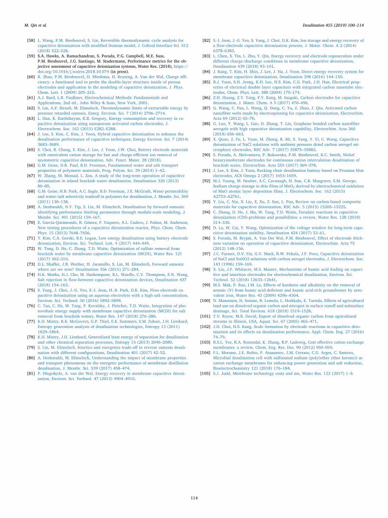
[58] L. Wang, P.M. Biesheuvel, S. Lin, Reversible thermodynamic cycle analysis forcapacitive deionization with modified Donnan model, J. Colloid Interface Sci. 512(2018) 522–528.
[59] S.A. Hawks, A. Ramachandran, S. Porada, P.G. Campbell, M.E. Suss,P.M. Biesheuvel, J.G. Santiago, M. Stadermann, Performance metrics for the ob-jective assessment of capacitive deionization systems, Water Res. (2018), https://doi.org/10.1016/j.watres.2018.10.074 (in press).
[60] R. Zhao, P.M. Biesheuvel, H. Miedema, H. Bruning, A. Van der Wal, Charge effi-ciency: a functional tool to probe the double-layer structure inside of porouselectrodes and application in the modeling of capacitive deionization, J. Phys.Chem. Lett. 1 (2009) 205–210.
[61] A.J. Bard, L.R. Faulkner, Electrochemical Methods: Fundamentals andApplications, 2nd ed., John Wiley & Sons, New York, 2001.
[62] S. Lin, A.P. Straub, M. Elimelech, Thermodynamic limits of extractable energy bypressure retarded osmosis, Energ. Environ. Sci. 7 (2014) 2706–2714.
[63] L. Han, K. Karthikeyan, K.B. Gregory, Energy consumption and recovery in ca-pacitive deionization using nanoporous activated carbon electrodes, J.Electrochem. Soc. 162 (2015) E282–E288.
[64] J. Lee, S. Kim, C. Kim, J. Yoon, Hybrid capacitive deionization to enhance thedesalination performance of capacitive techniques, Energy Environ. Sci. 7 (2014)3683–3689.
[65] S. Choi, B. Chang, S. Kim, J. Lee, J. Yoon, J.W. Choi, Battery electrode materialswith omnivalent cation storage for fast and charge-efficient ion removal ofasymmetric capacitive deionization, Adv. Funct. Mater. 28 (2018).
[66] G.M. Geise, D.R. Paul, B.D. Freeman, Fundamental water and salt transportproperties of polymeric materials, Prog. Polym. Sci. 39 (2014) 1–42.
[67] W. Zhang, M. Mossad, L. Zou, A study of the long-term operation of capacitivedeionisation in inland brackish water desalination, Desalination 320 (2013)80–85.
[68] G.M. Geise, H.B. Park, A.C. Sagle, B.D. Freeman, J.E. McGrath, Water permeabilityand water/salt selectivity tradeoff in polymers for desalination, J. Membr. Sci. 369(2011) 130–138.
[69] A. Deshmukh, N.Y. Yip, S. Lin, M. Elimelech, Desalination by forward osmosis:identifying performance limiting parameters through module-scale modeling, J.Membr. Sci. 491 (2015) 159–167.
[70] E. García-Quismondo, R. Gómez, F. Vaquero, A.L. Cudero, J. Palma, M. Anderson,New testing procedures of a capacitive deionization reactor, Phys. Chem. Chem.Phys. 15 (2013) 7648–7656.
[71] T. Kim, C.A. Gorski, B.E. Logan, Low energy desalination using battery electrodedeionization, Environ. Sci. Technol. Lett. 4 (2017) 444–449.
[72] W. Tang, D. He, C. Zhang, T.D. Waite, Optimization of sulfate removal frombrackish water by membrane capacitive deionization (MCDI), Water Res. 121(2017) 302–310.
[73] D.L. Shaffer, J.R. Werber, H. Jaramillo, S. Lin, M. Elimelech, Forward osmosis:where are we now? Desalination 356 (2015) 271–284.
[74] H.K. Mutha, H.J. Cho, M. Hashempour, B.L. Wardle, C.V. Thompson, E.N. Wang,Salt rejection in flow-between capacitive deionization devices, Desalination 437(2018) 154–163.
[75] S. Yang, J. Choi, J.-G. Yeo, S.-I. Jeon, H.-R. Park, D.K. Kim, Flow-electrode ca-pacitive deionization using an aqueous electrolyte with a high salt concentration,Environ. Sci. Technol. 50 (2016) 5892–5899.
[76] C. Tan, C. He, W. Tang, P. Kovalsky, J. Fletcher, T.D. Waite, Integration of pho-tovoltaic energy supply with membrane capacitive deionization (MCDI) for saltremoval from brackish waters, Water Res. 147 (2018) 276–286.
[77] K.H. Mistry, R.K. McGovern, G.P. Thiel, E.K. Summers, S.M. Zubair, J.H. Lienhard,Entropy generation analysis of desalination technologies, Entropy 13 (2011)1829–1864.
[78] K.H. Mistry, J.H. Lienhard, Generalized least energy of separation for desalinationand other chemical separation processes, Entropy 15 (2013) 2046–2080.
[79] S. Lin, M. Elimelech, Kinetics and energetics trade-off in reverse osmosis desali-nation with different configurations, Desalination 401 (2017) 42–52.
[80] A. Deshmukh, M. Elimelech, Understanding the impact of membrane propertiesand transport phenomena on the energetic performance of membrane distillationdesalination, J. Membr. Sci. 539 (2017) 458–474.
[81] P. Długołęcki, A. van der Wal, Energy recovery in membrane capacitive deioni-zation, Environ. Sci. Technol. 47 (2013) 4904–4910.
[82] S.-I. Jeon, J.-G. Yeo, S. Yang, J. Choi, D.K. Kim, Ion storage and energy recovery ofa flow-electrode capacitive deionization process, J. Mater. Chem. A 2 (2014)6378–6383.
[83] L. Chen, X. Yin, L. Zhu, Y. Qiu, Energy recovery and electrode regeneration underdifferent charge/discharge conditions in membrane capacitive deionization,Desalination 439 (2018) 93–101.
[84] J. Kang, T. Kim, H. Shin, J. Lee, J. Ha, J. Yoon, Direct energy recovery system formembrane capacitive deionization, Desalination 398 (2016) 144–150.
[85] B.J. Yoon, S.H. Jeong, K.H. Lee, H.S. Kim, C.G. Park, J.H. Han, Electrical prop-erties of electrical double layer capacitors with integrated carbon nanotube elec-trodes, Chem. Phys. Lett. 388 (2004) 170–174.
[86] Z.H. Huang, Z.Y. Yang, F.Y. Kang, M. Inagaki, Carbon electrodes for capacitivedeionization, J. Mater. Chem. A 5 (2017) 470–496.
[87] G. Wang, C. Pan, L. Wang, Q. Dong, C. Yu, Z. Zhao, J. Qiu, Activated carbonnanofiber webs made by electrospinning for capacitive deionization, Electrochim.Acta 69 (2012) 65–70.
[88] G. Luo, Y. Wang, L. Gao, D. Zhang, T. Lin, Graphene bonded carbon nanofiberaerogels with high capacitive deionization capability, Electrochim. Acta 260(2018) 656–663.
[89] X. Quan, Z. Fu, L. Yuan, M. Zhong, R. Mi, X. Yang, Y. Yi, C. Wang, Capacitivedeionization of NaCl solutions with ambient pressure dried carbon aerogel mi-crosphere electrodes, RSC Adv. 7 (2017) 35875–35882.
[90] S. Porada, A. Shrivastava, P. Bukowska, P.M. Biesheuvel, K.C. Smith, Nickelhexacyanoferrate electrodes for continuous cation intercalation desalination ofbrackish water, Electrochim. Acta 255 (2017) 369–378.
[91] J. Lee, S. Kim, J. Yoon, Rocking chair desalination battery based on Prussian blueelectrodes, ACS Omega 2 (2017) 1653–1659.
[92] M.J. Young, M. Neuber, A.C. Cavanagh, H. Sun, C.B. Musgrave, S.M. George,Sodium charge storage in thin films of MnO2 derived by electrochemical oxidationof MnO atomic layer deposition films, J. Electrochem. Soc. 162 (2015)A2753–A2761.
[93] Y. Liu, C. Nie, X. Liu, X. Xu, Z. Sun, L. Pan, Review on carbon-based compositematerials for capacitive deionization, RSC Adv. 5 (2015) 15205–15225.
[94] C. Zhang, D. He, J. Ma, W. Tang, T.D. Waite, Faradaic reactions in capacitivedeionization (CDI)-problems and possibilities: a review, Water Res. 128 (2018)314–330.
[95] D. Lu, W. Cai, Y. Wang, Optimization of the voltage window for long-term capa-citive deionization stability, Desalination 424 (2017) 53–61.
[96] S. Porada, M. Bryjak, A. Van Der Wal, P.M. Biesheuvel, Effect of electrode thick-ness variation on operation of capacitive deionization, Electrochim. Acta 75(2012) 148–156.
[97] J.C. Farmer, D.V. Fix, G.V. Mack, R.W. Pekala, J.F. Poco, Capacitive deionizationof NaCl and NaNO3 solutions with carbon aerogel electrodes, J. Electrochem. Soc.143 (1996) 159–169.
[98] X. Liu, J.F. Whitacre, M.S. Mauter, Mechanisms of humic acid fouling on capaci-tive and insertion electrodes for electrochemical desalination, Environ. Sci.Technol. 52 (2018) 12633–12641.
[99] M.S. Mak, P. Rao, I.M. Lo, Effects of hardness and alkalinity on the removal ofarsenic (V) from humic acid-deficient and humic acid-rich groundwater by zero-valent iron, Water Res. 43 (2009) 4296–4304.
[100] N. Manninen, H. Soinne, R. Lemola, L. Hoikkala, E. Turtola, Effects of agriculturalland use on dissolved organic carbon and nitrogen in surface runoff and subsurfacedrainage, Sci. Total Environ. 618 (2018) 1519–1528.
[101] T.V. Royer, M.B. David, Export of dissolved organic carbon from agriculturalstreams in Illinois, USA, Aquat. Sci. 67 (2005) 465–471.
[102] J.H. Choi, H.S. Kang, Scale formation by electrode reactions in capacitive deio-nization and its effects on desalination performance, Appl. Chem. Eng. 27 (2016)74–79.
[103] R.S.L. Yee, R.A. Rozendal, K. Zhang, B.P. Ladewig, Cost effective cation exchangemembranes: a review, Chem. Eng. Res. Des. 90 (2012) 950–959.
[104] F.L. Moruno, J.E. Rubio, P. Atanassov, J.M. Cerrato, C.G. Arges, C. Santoro,Microbial desalination cell with sulfonated sodium (poly(ether ether ketone)) ascation exchange membranes for enhancing power generation and salt reduction,Bioelectrochemistry 121 (2018) 176–184.
[105] S.J. Judd, Membrane technology costs and me, Water Res. 122 (2017) 1–9.
M. Qin et al. Desalination 455 (2019) 100–114
114