comparison of fuel cell and internal … · cl 152-choose focus and analyse exercise comparison of...
TRANSCRIPT

CL 152-CHOOSE FOCUS AND ANALYSE EXERCISE
COMPARISON OF FUEL CELL AND INTERNAL COMBUSTION
ENGINE
PRESENTED BY:ISHANK KUMAR ROLL NO.:01D02015
DATE:09.04.2002

Acknowledgement
I’m grateful to Prof. G.K. Suresh Kumar for introducing me to the concepts of mass and energy balance. I would like to thank P.S. Bedi(01D0201) for providing me data on internal combustion engine inlet and outlet streams. I would like to thank Sandeep S(01001004) for making the pdf version of this word document.

Contents �
Introduction. � Processing unit of fuel cell.
1. Removal of Sulphur. 2. Hydrogen from hydrocarbon. 3. Role of catalyst. �
Problem statements and assumptions on fuel cell � Applying material balance on fuel cell. � Applying energy balance on fuel cell. � Problem statements and assumptions on internal combustion engine �
Applying material balance on internal combustion engine. � Applying energy balance on internal combustion engine. � Conclusion � Bibliography.

INTRODUCTION Fuel Cells was the topic of our group presentation (group-8). Searching on this topic, I came to know about the various aspects of this topic. Fuel cell are considered a future hope for this world which is polluted to a rapid pace by the increasing use of petroleum, etc. and those who are aware of energy needs of the world on this stage where consumption of petroleum is increasing but no major discovery in petroleum is done. The exact amount of proved and unproved petroleum reserves remaining in the world is not exactly known; but approximately we have used 1 billion barrels of oil and nearly that much amount of petroleum is still remaining. At the present rate of consumption, petroleum reserves of the world will last this century only. Due to low production and high demand cost of petroleum is expected to increase very rapidly. Worst effect of this will be on transport sector of the whole world; which more or less depends on the petroleum for its fuel and energy needs. Fuel Cell can be a better alternative to internal combustion engine in the future because a large number of compounds (example methane, methanol, petroleum, H2 from hydel power, natural gas) can be used as fuel cells. In the present scenario, where H2 based economy are not cost effective due to lack of infrastructure, fuel cell running on petroleum can be used because of its high efficiency and lower emission. This will give us more time to work on other alternative ways. Utility of fuel cells can be recognized by billions of dollars spent for its development by different automobile companies. In this report, I’ m trying to compare the fuel cell vehicles an internal combustion engine in terms of exhaust gases and energy produced. In the absence of the exact data for the fuel cell vehicle, I have considered data for fuel cell power plant emission from the fuel cell handbook and assumed many other data that led to nearly the same inlet and outlet stream as given in the book. The data for internal combustion engine are taken from P.S. Bedi’ s report (NO2 , CO percentage in the outlet stream and the composition of the inlet stream) on which I applied mass and energy balances. Final results may get deviated from the actual figures, about which(the deviation) I have no idea; but I have tried my best not to be far from the actual results.

PROCESSING UNIT OF FUEL CELL 1.REMOVAL OF SULPHUR:- Sulphur content is decreased before the reforming Process during clean up stage,
because it can affect the working of reforming catalyst or fuel cells themselves. The most common industrial process is hydrodesulphurization.In this process,dry vapourised fuel is reacted over a Co-Mb catalyst with excess H2 to convert organic sulphur compounds to H2S and hydrocarbons i.e.
RSH + H2_ RH + H2 S In the next stage,H2S produced is removed by passing it over a Zinc oxide bed.
ZnO + H2S ZnS (ppt) + H2 O
Complete regeneration of zinc bed is accomplished by air oxidation at 6500C. It has been observed that this process is capable of lowering H2S level to less than 10 ppm for hot coal gases. 2. HYDROGEN FROM HYDROCARBON:- Hydrogen can be removed fromjydrocarbon by steam reforming process. Excess steam and hydrocarbons in a ratio of 2-3 moles of water per mole of carbon arereacted over a catalyst in a temperature range that is normally between 4500c (inlet) and between 8000c (hot zone) to obtain optimum rates. Hydrocarbon is converted to carbon monoxide in step 1
CnH2n +2 + n H2O (2n+1)H2 + nCO For unsaturated hydrocarbon, it will be
CnH2n + n H2O (2n)H2 + nCO
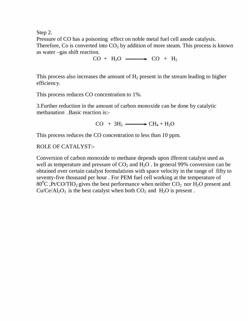
Step 2. Pressure of CO has a poisoning effect on noble metal fuel cell anode catalysis. Therefore, Co is converted into CO2 by addition of more steam. This process is known as water –gas shift reaction.
CO + H2O CO + H2
This process also increases the amount of H2 present in the stream leading to higher efficiency.
This process reduces CO concentration to 1%.
3.Further reduction in the amount of carbon monoxide can be done by catalytic methanation .Basic reaction is:-
CO + 3H2 CH4 + H2O
This process reduces the CO concentration to less than 10 ppm.
ROLE OF CATALYST:-
Conversion of carbon monoxide to methane depends upon ifferent catalyst used as well as temperature and pressure of CO2 and H2O . In general 99% conversion can be obtained over certain catalyst formulations with space velocity in the range of fifty to seventy-five thousand per hour . For PEM fuel cell working at the temperature of 800C ,Pt/CO/TIO2 gives the best performance when neither CO2 nor H2O present and Cu/Ce/Al2O3 is the best catalyst when both CO2 and H2O is present .
Problem Statement
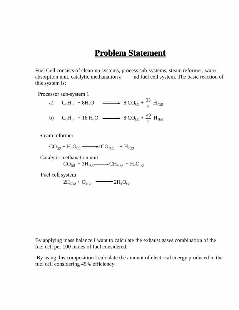
Fuel Cell consists of clean-up systems, process sub-systems, steam reformer, water absorption unit, catalytic methanation a nd fuel cell system. The basic reaction of this system is:
Processor sub-system 1
a) C8H17 + 8H2O 8 CO(g) + 2
33 H2(g)
b) C8H17 + 16 H2O 8 CO(g) + 2
49 H2(g)
Steam reformer
CO(g) + H2O(g) CO2(g) + H2(g)
Catalytic methanation unit CO(g) + 3H2(g) CH4(g) + H2O(g)
Fuel cell system 2H2(g) + O2(g) 2H2O(g)
By applying mass balance I want to calculate the exhaust gases combination of the fuel cell per 100 moles of fuel considered.
By using this composition I calculate the amount of electrical energy produced in the fuel cell considering 45% efficiency.

Assumptions:
For Material balance:
1. In the fuel processor subsystem 60% of the total fuel cell converts in CO and overall fuel conversion is 95%.
2. Inlet stream is considered to be 100 moles of C8H17. fuel.
3. In steam reforming unit efficiency of conversion is 90%.
4. In water absorbing unit 100% water is absorbed.
5. In catalytic methanation unit efficiency of conversion is 99%.
6. In fuel cell system conversion of H2 is 95%.
For Energy balance:
1. Fuel and water are considered to be at room temperature of 250C during inlet stream of fuel cell vehicles and then heated but no separate energy balance is applied.
2. Fuel processor unit is assumed to run at a temperature of 6500C
3. Fuel Cell is assumed to run at a temperature of 4000C.
4. Velocity of inlet and outlet gases are assumed to be 0 and overall efficiency of the system is 50%.
5. No balance is applied on the absorbing unit.

Applying Material Balance :-
1. Material Balance on processor subsystem .
Reactions are:-
c) C8H17 + 8H2O 8 CO(g) + 2
33 H2(g)
d) C8H17 + 16 H2O 8 CO(g) + 2
49 H2(g)
Conversion of fuel = 95%
Conversion into CO = 60% of total conversion
a) Material balance on C8H17.
I + G – O – C = A
G=0
O=0
I=100 mol.
C= 100 * 100
95 = 95 mol.
... A = 100 – 95 = 5 mol.

b) Applying material balance on CO.
I + G – O – C = A
I=0; C=0; A=0
... G=O
Generation = 100
60*8 * 95 = 456 mol. = output.
c) Applying balance on CO2
I + G – O – C = A
I=0; C=0; A=0
... G=O
Generation = 40 * 8*100
95 = 304 mol. = output.
d) Applying balance on H2O
I + G – O – C = A
G=0; A=0
I= 2500 mol.
C= 95 * 8*100
60*9516*95*
100
40 + = 1064 mol.
... O =I – C
=2500 – 1064
= 1436 mol.
e) Applying balance on H2
I + G – O – C = A
I=0; C=0; A=0
... G=O
G= �����
+ 95*100
40*
2
4995*
100
60*
2
33 mol.

=1871.5 mol.
Therefore, outlet stream through subsystem 1. is
CO 456 mol.
CO2 304 mol.
H2O 1436 mol.
H2 1871.5mol.
C8H17 5 mol.
2. Material balance on stream reformer
In stream reformer ,
CO(g) + H2O(g) CO2(g) + H2(g)
Efficiency of conversion = 90%
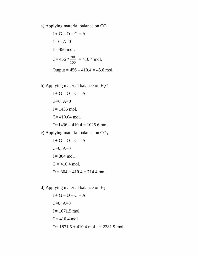
a) Applying material balance on CO
I + G – O – C = A
G=0; A=0
I = 456 mol.
C= 456 *100
90 = 410.4 mol.
Output = 456 – 410.4 = 45.6 mol.
b) Applying material balance on H2O
I + G – O – C = A
G=0; A=0
I = 1436 mol.
C= 410.04 mol.
O=1436 – 410.4 = 1025.6 mol.
c) Applying material balance on CO2
I + G – O – C = A
C=0; A=0
I = 304 mol.
G = 410.4 mol.
O = 304 + 410.4 = 714.4 mol.
d) Applying material balance on H2
I + G – O – C = A
C=0; A=0
I = 1871.5 mol.
G= 410.4 mol.
O= 1871.5 + 410.4 mol. = 2281.9 mol.

Outlet Stream :-
CO 45.6 mol.
CO2 714.4 mol.
H2O 1025.6 mol.
H2 2281.9mol.
C8H17 5 mol.
3. When passed through water absorbing unit, 100% of water is absorbed Output Stream :- CO 456 mol.
CO2 304 mol.
H2 1871.5mol.
C8H17 5 mol.
4. Catalytic Methanation unit Reaction :- CO(g) + 3H2(g) CH4(g) + H2O(g) Conversion of CO = 99%

a) Applying Material balance on CO I + G – O – C = A
G=0;
I = 45.6 mol.
C=100
99*6.45 = 45.14 mol.
O = 45.6 – 45.14 = 0.46 mol. b) Material balance on H2
I + G – O – C = A
G=0; A=0
I = 2281.9 mol.
C=100
99*6.45 *3= 45.14 * 3 = 135.42 mol.
O=2281.9 – 135.42 = 2196.48 mol. c) Material balance on CO2
I + G – O – C = A
G=0; A=0; C=0
I = O = 714.4 mol.

d) Material balance on CH4
I + G – O – C = A
I=0; C=0; A=0
G = O = 45.14 mol.
e) Material balance on H2O
I + G – O – C = A
I=0; C=0; A=0
G = O = 45.14 mol.
Product stream : - MCO = 0.46 mol MCO2=714.4 mol. MH2 = 2146.48 mol. MH2O=45.14 mol MC8H17=5mol. MCH4 = 45.14 mol. Therefore, the product stream from system 1 i.e. fuel processor is MCO = 0.46 mol MCO2=714.4 mol. MH2 = 2146.48 mol. MH2O=45.14 mol MC8H17=5mol. MCH4 = 45.14 mol.

Fuel Cell System
200 % Excess Air considered. Conversion of H2=95%
Reaction:-
2H2(g) + O2(g) 2H2O(g)
(moles air)the= moles of air containing the oxygen required for
reaction
= 2
48.2146*
232.0
1 = 4626.03 mol.
... (moles air)fed = 3 * (moles air)the
= 3*4626.03 mol.
= 13878.10 mol.

a) Applying material balance on H2
I + G – O – C = A
G=0; A=0;
I = 2146.48 mol.
C= 2146.48 * 100
95 = 2039.15 mol.
O = I – C
= 2146.48 – 2039.15 = 107.33 mol.
b) Applying material balance on O2
I + G – O – C = A
G=0; A=0;
I = 1073.24 *3 = 3219.72 mol.
C= 2
15.2039 = 1019.575 mol.
O = 3219.72 – 1019.575 mol.
= 2200.145 mol.
c) Applying material balance on N2
I + G – O – C = A
G=0; C=0; A=0
I = O = 13878.1*0.768
= 10658.38 mol.

d) Applying material balance on CO2
I + G – O – C = A
G=0; C=0; A=0;
I = O = 714.4 mol.
Similarly, MCH4 = 45.14 mol.
MCO = 0.46 mol.
e) Applying material balance on H2O
I + G – O – C = A
C=0; A=0;
I = 45.14 mol.
G = 2146.48 mol.
O = 2146.48 + 45.14 = 2191.62 mol.
Thus Final Stream coming out from fuel cell
MH2 = 107.83 mol.
MO2 = 2200.145 mol.
MN2 = 10658.38 mol.
MCO2=714.4 mol.
MCH4=45.14 mol.
MCO = 0.46 mol.
MH2O=2191.42 mol.
MC8H17=5 mol.

Applying Energy Balance on Fuel Cell
MCO=456 mol
Applying energy balance on processor subsystem 1
Considering Energy Balance,
I + G – C – O = A
[ � mi ( � o + ½ uo2 + gzo + . . . . . . )] - � [ mj ( � j + ½ ui
2 + gzj + . . . . .) ] +
dEcv/dt = Q - Ws
uo = zo = ui = zj = dEcv/dt = Ws
� mo � o - � mj � j = Q
Basis: 1 mole of C8H17 at 25oC
Reactant
Component
gm Mol. T(K) �� (J/gmole) �� of
(J/gmol.)
� H(104J)
C8H17 100 298 0 -224,400 -2244
H2O 2500 298 0 -241,826 -60456.5
� Hr= -627,005,000 J

Products Gmole. T(K) �� sen(J/gmol.) �� of
(J/gmol.)
� H(104J)
C8H17 5 900 147.65(900-298) -187,800 -49.45735
H2O 1436 900 22,760-837 -241,826 -31578.0708
CO 456 900 19125-728 -110,520 -4200.8088
CO2 304 900 28,936-912 -393,510 -11110.7744
H2 1871.5 900 18,384-718 0 3306.1919
� Hp=-436329194.5 J
Q= � H p - � H r =194375805.5 J
Energy Balance on steam reformer unit
Energy balance:-
� H(J)r = � H(J)p of last unit

� Hp = -451026118.5 J
Q= � Hp - � Hr
Q=-14696924 J
Energy Balance on Catalytic Methanation Unit
Products Gmol. T(K) �� (J/gmol.) � Hof(J/gmol.) � H(J)
CO 45.6 900 19125-728 -110520 -4200808.8
CO2 714.4 900 28,936-912 -393510 -261103198.4
H2 2281.9 900 18384-718 0 40304979
H2O 1025.6 900 22760-837 -241826 -225532516.8
C8H17 5 900 147.65(900-298) -187800 -494573.5
Products Gmol. T(K) � H(J/gmol.) �� of(J/gmol.) � H(J)
C8H17 5 900 88885.3 -187800 -494573.5
CO 0.46 900 19125-728 -110520 -42376.58
CO2 714.4 900 28936-912 -393510 -261103198.4
H2O 45.14 900 22760-837 -241826 -9850857.06
H2 2146.48 900 18834-718 0 38885631.68
CH4 45.14 900 32204-879 -74840 -1941697.1

� Hp=-234547071 J
Q=-9053469.3
Energy balance on fuel cell system
Components Gmol T(K) �� (J/gmol) �� of(J/gmol) � H(J)
N2 10658.38 400 3695-728 0 31623413.46
O2 3219.7 400 3752-732 0 9723494
Rest of the data taken from the last unit.
� Hr=-193200163.5 J

Products Gmol T(K) �� (J/gmol) �� of(J/gmol) � H(J)
H2 107.33 400 3655-718 0 315228.21
O2 2200.145 400 3752-732 0 6644437.9
N2 10658.38 400 3695-728 0 31623413.46
CO2 714.4 400 4903-912 -393520 -278272373.6
CO 0.46 400 3699-728 -110520 -49472.54
H2O 2191.62 400 4284-837 -241826 -522436184
CH4 45.14 400 4740-879 -74840 -3203992.06
C8H17 5 400 147.65(400-298) -187800 -863698.5
� Hp=-766242641.1 J
Q=-573042477.6 J
Overall energy change =
Energy change in processor subsystem 1 + Energy change in steam reformer unit +
Energy change in catalytic methanation unit + Energy change in fuel cell system =
194375805.5 - 14696924 - 9053469 - 573042477.6 = -402417065.4 J
Considering the electrical efficiency of the fuel cell as 45%
Energy produced per 100 moles of fuel consumed = -402417065.4 * 45%
= -181087679.4 J

Problem Statement
Inlet fuel stream of internal combustion engine is assumed to be 96.226%.
Hydrocarbon (assumed to be only C8H17) , 0.0017% sulphur, 3.6% C6H6 , 0.0002%
Pb (by mass) at 250 C. The air is assumed to be mixed in 1:15 ratio by mass for which
system gives best result. Reaction in the internal combustion engine is assumed to be
900 K. I have assumed NO2 = 1.04kg. and CO = 48kg in the final stream and
percentage conversion into CO and CO2 are derived from that assuming efficiency of
fuel conversion to be 95%. Using this data and concept of mass and energy balance I
have calculated the exhaust gas composition and considering 35% conversion of total
heat generated into heat supplied. I have calculated the data for heat generation. It is
assumed that inlet and outlet velocities are negligible. In considering energy balance
Benzene and Lead are not considered.
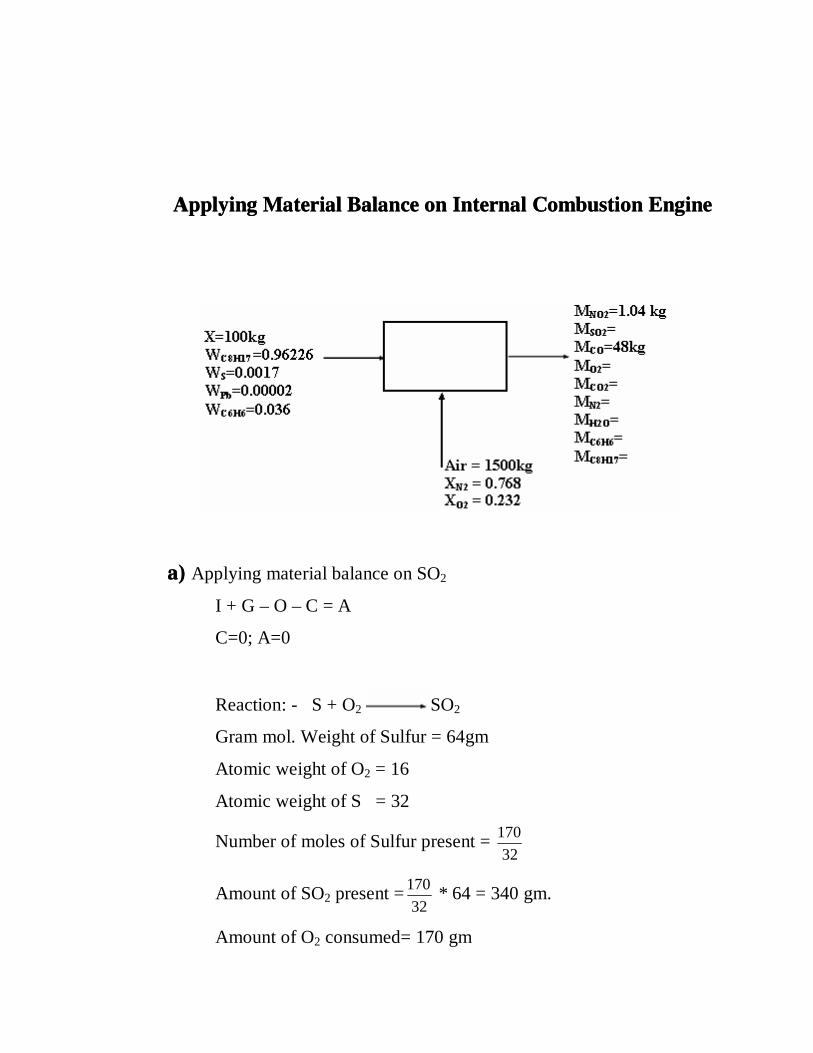
Applying Material Balance on Internal Combustion Engine
a) Applying material balance on SO2
I + G – O – C = A
C=0; A=0
Reaction: - S + O2 SO2
Gram mol. Weight of Sulfur = 64gm
Atomic weight of O2 = 16
Atomic weight of S = 32
Number of moles of Sulfur present = 32
170
Amount of SO2 present =32
170 * 64 = 340 gm.
Amount of O2 consumed= 170 gm

b) Applying material balance on CO2
I + G – O – C = A
I=0; C=0; A=0;
Reaction:-
C8H17 + 4
49 O2 8CO2 + 2
17 H2O
G= 8* 594.69 mol. = 4757.52 mol.
Mass of CO2 produced = 209.330 kg
c) Applying material balance on H2O
I + G – O – C = A
I=0; C=0; A=0;
... G =O
= 2
17*69.59428.214*
2
17 + = 6876.245 mol.
Amount of H2O in final stream = 123.772 kg
d) Material balance on O2
I + G – O – C = A
G=0; A=0;
Reactions :-
S + O2 SO2
C8H17 + 4
33 O2 8CO + 2
17 H2O
C8H17 + 4
49 O2 8CO2 + 2
17 H2O

Considering that about 48 kg of Carbon monoxide is produced from 100
kg of fuel with the assumption considered above, we calculate the present
conversion of fuel into CO and CO2.
Reaction:-
C8H17 + 4
33 O2 8CO + 2
17 H2O
No. of moles of CO per 100kg of fuel = 28
1000*48
No. of moles of C8H17 consumed =8*28
1000*48 = 214.28 mol.
No. of moles of C8H17 in 96.226*103 gram = 113
1000*226.96
=851.55mol.
No. of moles of C8H17 consumed
(assuming 95% conversion) = 100
95*55.851 = 808.97 mol.
Amount of C8H17 consumed for production of CO2
= 808.97 – 214.28 = 594.69 mol.
Amount of C8H17 in the final stream = (851.55 – 808.97) * 113
= 4.81kg
iii) 2
1 N2 + O2 NO2
iv) 2 Pb+O2 PbO

For NO2 production of 1.04kg
Moles of Oxygen needed =46
1000*04.1
Amount of Oxygen = 46
1000*04.1 * 32 = 723.47 gm
Amount of Nitrogen = 46
1000*04.1 * 14 = 0.316 kg
Neglecting loss of O2 in PbO ,
I = 1500 * 0.232 kg = 348 kg
C= 0.170 + 0.723 + 100
32*
4
33*28.214
4
49*69.594 �
� ��+ = 290.573 kg
O = I – C = 348 kg – 290.573 kg = 57.427 kg
e) Material balance on N2
I = 1500 * 0.768 = 1152 kg
C= 0.316 kg
G=0
O= 1152 – 0.316 = 1151.684 kg
Final production stream
MNO2 =1.04kg MN2 = 1151.684kg
MSO2 =0.34kg MC8H17=4.81kg
MCO =48kg MC6H6=0.36kg
MCO2 =209.33kg MPbO=0.002 kg
MO2 =57.42kg MH2O =123.772 kg

Applying energy balance on internal combustion engine
[ � mi ( � o + ½ uo2 + gzo + . . . . . . )] - � [ mj ( � j + ½ ui
2 + gzj + . . . . .) ] +
dEcv/dt = Q - Ws
Ws= dEcv/dt = uo= ui=0
Therefore ,
� mi ��� o - � mj ��� j = Q
For reactant stream
Basis 1 mol at 25oC.
� Hf = -191087820 J
Components Gmol T(K) � Hsen(J) �� of(J) � H(J)
C8H17 851.55 298 0 -224400 -191087820
N2 41142 298 0 0 0
O2 10875 298 0 0 0
S 5.3125 298 0 0 0
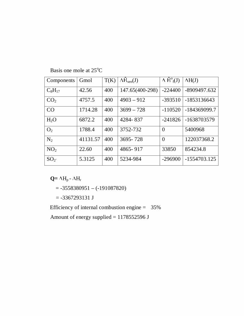
Basis one mole at 25oC
Components Gmol T(K) �� sen(J) � � of(J) � H(J)
C8H17 42.56 400 147.65(400-298) -224400 -8909497.632
CO2 4757.5 400 4903 – 912 -393510 -1853136643
CO 1714.28 400 3699 – 728 -110520 -184369099.7
H2O 6872.2 400 4284- 837 -241826 -1638703579
O2 1788.4 400 3752-732 0 5400968
N2 41131.57 400 3695- 728 0 122037368.2
NO2 22.60 400 4865- 917 33850 854234.8
SO2` 5.3125 400 5234-984 -296900 -1554703.125
Q= � Hp - � Hr
= -3558380951 – (-191087820)
= -3367293131 J
Efficiency of internal combustion engine = 35%
Amount of energy supplied = 1178552596 J

Conclusion
It has been observed that amount of CO2 and CO produced in the case of fuel
cell is very low as compared to internal combustion engine.Considering 100 mole of
fuel , in both fuel cell and internal combustion engine, the amount of CO2 produced in
internal combustion engine is 23.65kg while in fuel cell it is 3.14 kg.Similar
observation is obtained for CO production .In internal combustion engine this is 5.4kg
per 100mol while in fuel cell it is negligible.Considering energy supplied by both the
cells with in the limit of our assumption it has been observed that the ratio of energy
supplied is 1.35 in the favour of fuel cell. Thus, fuel cell is a better alternative to
internal combustion engine.

Bibliography
1.Internal Combustion engine and air pollution.
Edward F Obert
2. A Fuel cell handbook A J Appleby.
3. Fuel cell –Modern processes for the electrochemical production of energy
Wolf Vielstich
4.Fuel Cells
Symposium proceedings
5.www.h2fc.com
6. www.fuelcells.org.com