comparison of pid tuning techniques for closed loop ... · pdf fileinternational journal of...
TRANSCRIPT

International Journal of Advances in Engineering & Technology, Feb., 2015.
©IJAET ISSN: 22311963
2064 Vol. 8, Issue 1, pp. 2064-2073
COMPARISON OF PID TUNING TECHNIQUES FOR CLOSED
LOOP CONTROLLER OF DC-DC BOOST CONVERTER
Apekshit Bhowate and Shraddha Deogade School of Electrical Engineering,
VIT University Chennai Campus, Chennai, India
ABSTRACT The capability of PID controller to withstand practical industrial problems has led to its inclusive acceptance in
industries and academics. It has been observed that PID controller tuning is quite difficult by classical methods using
graphs and mathematical analysis. In this paper, PID theory is briefly summarized and some standard tuning methods
are discussed using MATLAB. Accordingly compensator transfer function is derived by different methods and
compared based on the steady state response and system characteristics. This effort inspects which method is best for
conventional DC-DC boost converter.
KEYWORDS: PID controller, tuning methods, MATLAB simulation, loop shaping.
I. INTRODUCTION
In SMPS (Switched-mode power supply) DC-DC boost converter has played very important for handling
high power. Boost converters are used in applications like photovoltaic (PV), hybrid electric vehicles
(HEV), battery charging and aerospace industries for regulated power supply. In PV application the output
of panel changes due to insolation level and temperature change. Whereas in HEV, Li-Po batteries [11] [12]
are used where output changes according to discharging characteristics and the load change. So there is
need of closed loop for boost converter in these applications. The load must be supplied with regulated
power supply, keeping watch on the system characteristics like peak response, settling time, rise time and
steady state. To achieve this, proportional integral derivative (PID) controller is used. PID controller is
being used in 90% [7] of industries. PID is extensively used for it is simple in structure and has standard
performance for most of the industries. But it is quite challenging to find gains of PID to meet response
time and overshoot (phase margin) specifications. Manual tuning is purely trial and error process, time
consuming and non-systematic. It may not produce optimal design and can lead to dangerous conditions.
So some standard design procedures had been introduced like Ziegler-Nichols method, Chien-Hrones-
Reswick method and pure numerical optimization approach (MIGO).
For analysis of a control system first a mathematical model of the boost converter is derived by state space
averaging techniques [1]. The transfer function thus obtained is used to find the gains of controllers by
different tuning methods mentioned above.
In this paper in section II basic theory of PID controller is given. In section III design of boost converter
with control transfer function (Gvd) is presented [2]. In section IV different tuning methods are discussed
and their respective compensator transfer functions are given. Various tuning methods are compared in
section V with system characteristics. Finally the tuning method with best performance is chosen and is
implemented to designed boost converter. The resultant control system is tested in simulation with dynamic
load change and input voltage change.
International Journal of Advances in Engineering & Technology, Feb., 2015.
©IJAET ISSN: 22311963
2065 Vol. 8, Issue 1, pp. 2064-2073
II. MODEL OF PID CONTROLLER
The PID controller is used to regulate the time domain characteristics of the control system [5]. The
governing s-domain equation is as follows;
The error signal is difference between set point and measured plant output. The proportional gain is directly
proportional to the measured error. When the proportional gain is increased steady state error is reduced
but the affinity of oscillation in system increases. System may become unstable if the proportional gain is
very high. When the integral gain increases the steady state error is vanished and peak overshoot increases.
As the derivative gain increases, the peak overshoot and settling time decreases. On the other hand, it
improves the stability of the system. Error signal always contains noise and when it is being differentiated
noise is just amplified. So the good way to implement the derivative term is to filter the noise with low pass
filter (N) and then differentiate them. So there must be compromise between these gains so as to get desired
system performance. This is achieved by using different PID tuning methods.
III. DESIGN OF BOOST CONVERTER
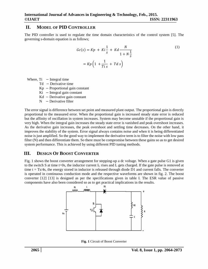
Fig. 1 shows the boost converter arrangement for stepping-up a dc voltage. When a gate pulse G1 is given
to the switch S at time t=0s, the inductor current IL rises and L gets charged. If the gate pulse is removed at
time t = Ts/4s, the energy stored in inductor is released through diode D1 and current falls. The converter
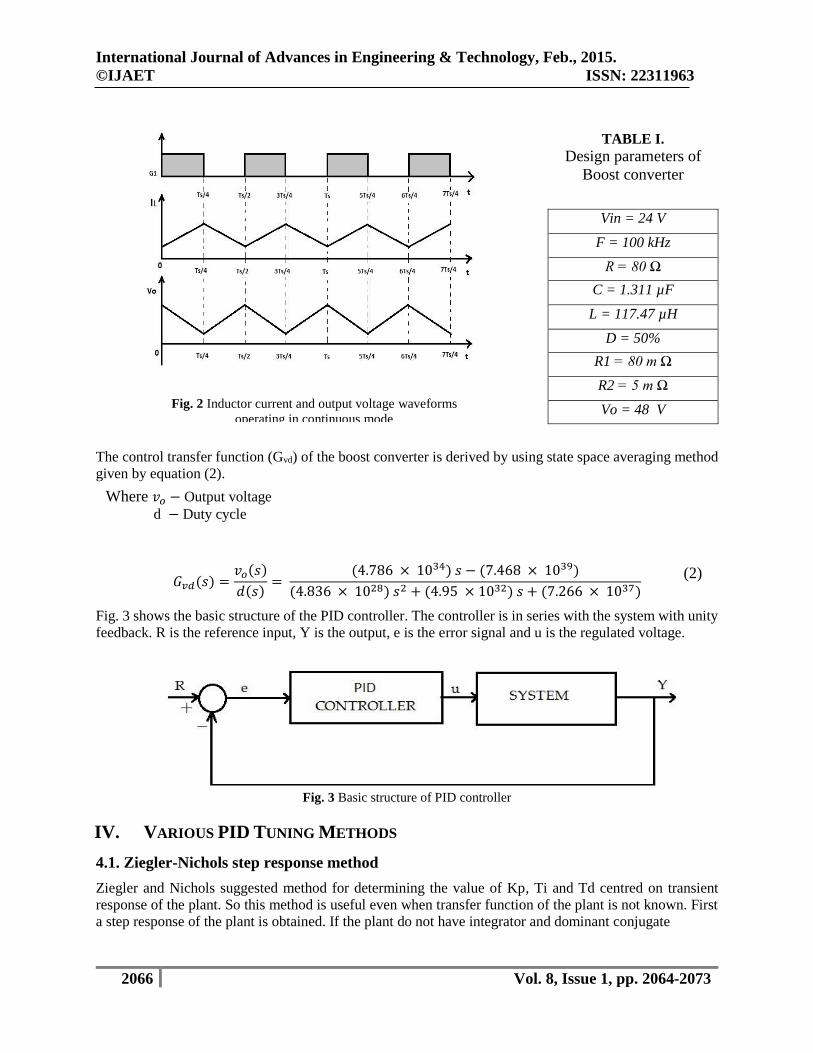
is operated in continuous conduction mode and the respective waveforms are shown in fig. 2. The boost
converter [12] [13] is designed as per the specifications given in table I. The ESR value of passive
components have also been considered so as to get practical implications in the results.
(1)
Where, Ti − Integral time
Td − Derivative time
Kp − Proportional gain constant
Ki − Integral gain constant
Kd − Derivative gain constant
N − Derivative filter
Fig. 1 Circuit of Boost Converter
𝐺𝑐(𝑠) = 𝐾𝑝 + 𝐾𝑖1
𝑠 + 𝐾𝑑
𝑁
1 + 𝑁1𝑠
= 𝐾𝑝 (1 +1
𝑇𝑖 𝑠 + 𝑇𝑑 𝑠)
International Journal of Advances in Engineering & Technology, Feb., 2015.
©IJAET ISSN: 22311963
2066 Vol. 8, Issue 1, pp. 2064-2073
The control transfer function (Gvd) of the boost converter is derived by using state space averaging method
given by equation (2).
𝐺𝑣𝑑(𝑠) =𝑣𝑜(𝑠)
𝑑(𝑠)=
(4.786 × 1034) 𝑠 − (7.468 × 1039)
(4.836 × 1028) 𝑠2 + (4.95 × 1032) 𝑠 + (7.266 × 1037)
Fig. 3 shows the basic structure of the PID controller. The controller is in series with the system with unity
feedback. R is the reference input, Y is the output, e is the error signal and u is the regulated voltage.
Fig. 3 Basic structure of PID controller
IV. VARIOUS PID TUNING METHODS
4.1. Ziegler-Nichols step response method
Ziegler and Nichols suggested method for determining the value of Kp, Ti and Td centred on transient
response of the plant. So this method is useful even when transfer function of the plant is not known. First
a step response of the plant is obtained. If the plant do not have integrator and dominant conjugate
Vin = 24 V
F = 100 kHz
R = 80 Ω
C = 1.311 µF
L = 117.47 µH
D = 50%
R1 = 80 m Ω
R2 = 5 m Ω
Vo = 48 V
(2)
TABLE I. Design parameters of
Boost converter
Fig. 2 Inductor current and output voltage waveforms
operating in continuous mode
Where 𝑣𝑜 − Output voltage
d − Duty cycle

International Journal of Advances in Engineering & Technology, Feb., 2015.
©IJAET ISSN: 22311963
2067 Vol. 8, Issue 1, pp. 2064-2073
TABLE II. Ziegler-Nichols Tuning Rule Based on Step Response of Plant
poles then the unit step response curve will show S-shaped curve. This curve have two constants, delay
time L and time constant T as shown in fig.4 [11] [15]. These constants are obtained by drawing a tangent
at the inflection point of the curve and find the intersection of the tangent with time axis and line c(t) = K.
The compensator transfer function can be obtained by the formulae given in the table II. The compensator
transfer function is given by equation (3) and step response with Ziegler-Nichols PID tuning is given in fig.
5.
𝐶 = −245.19 × (1 + (4.1 × 10⁻⁵)𝑠 + (4.41 × 10⁻¹⁰)𝑠2)
𝑠(1 + (9.9 × 10⁻⁷)𝑠)
Fig. 4 Step response of plant (s-shaped curve)
Type of Controller Kp Ti Td
P 1
𝑎
∞ 0
PI 0.9
1
𝑎
3L 0
PID 1.2
1
𝑎
2L 0.5L
(3)

International Journal of Advances in Engineering & Technology, Feb., 2015.
©IJAET ISSN: 22311963
2068 Vol. 8, Issue 1, pp. 2064-2073
Fig. 5 Step response of plant with Ziegler-Nichols tuning
4.2. Chien-Hrones-Reswick method
The Chien-Hrones-Reswick (CHR) PID tuning is also called modified Ziegler-Nichols method. This
method accentuates on the set point regulation or noise rejection. Also the response of the system and
overshoot can be controlled. This method uses the time constant T explicitly than the Ziegler-Nichols tuning
formula. This method gives better performance even at higher order (more than two). The design formulae
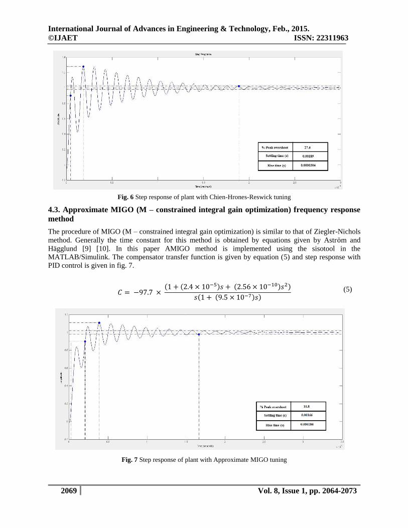
for 20% overshoot is given in table III. The compensator transfer function is given by equation (4) and step
response with PID control is given in fig. 6.
𝐶 = −163.11 × (1 + (1.2 × 10⁻⁵)𝑠) (1 + (3.6 × 10⁻⁵)𝑠)
𝑠(1 + (8.3 × 10⁻⁷)𝑠)
TABLE III. Chien-Hrones-Reswick Tuning Rule Based on Step Response of Plant
Overshoot 20%
Type of Controller Kp Ti Td
P 0.3
𝑎
∞ 0
PI 0.35
1
𝑎
1.2𝑇 0
PID 0.6
1
𝑎
T 0.5L
(4)
International Journal of Advances in Engineering & Technology, Feb., 2015.
©IJAET ISSN: 22311963
2069 Vol. 8, Issue 1, pp. 2064-2073
Fig. 6 Step response of plant with Chien-Hrones-Reswick tuning
4.3. Approximate MIGO (M – constrained integral gain optimization) frequency response
method
The procedure of MIGO (M – constrained integral gain optimization) is similar to that of Ziegler-Nichols
method. Generally the time constant for this method is obtained by equations given by Aström and
Hägglund [9] [10]. In this paper AMIGO method is implemented using the sisotool in the
MATLAB/Simulink. The compensator transfer function is given by equation (5) and step response with
PID control is given in fig. 7.
𝐶 = −97.7 × (1 + (2.4 × 10⁻⁵)𝑠 + (2.56 × 10⁻¹⁰)𝑠2)
𝑠(1 + (9.5 × 10⁻⁷)𝑠)
Fig. 7 Step response of plant with Approximate MIGO tuning
(5)

International Journal of Advances in Engineering & Technology, Feb., 2015.
©IJAET ISSN: 22311963
2070 Vol. 8, Issue 1, pp. 2064-2073
4.4. Loop shaping method
The loop shaping is a design method in which the compensator transfer function is designed such that the
response gets the desired shape. This method is easy to implement. The compensator transfer function is
designed with the help of root locus plots. First, the desired parameters are added in the sisotool and
accordingly the region of stability is highlighted in the step response plot [17]. By adding poles and zeros
in the root locus plot desired shape of loop is achieved within the highlighted region. The compensator
transfer function’s step response with loop shaping PID tuning is given in fig. 8. The gain constants obtained
are, Kp = 11.2222, Ki = 62234.0092, Kd = 0.00025621 and N =5.
Fig. 8 Step response of plant with loop shaping method
V. COMPARISON OF DISCUSSED TUNING METHODS
Various tuning methods comparison is given in table IV. It is observed that loop shaping method gives best
performance in terms of less peak overshoot, less settling time and less rise time. Moreover, loop shaping
method is easy to implement with MATLAB/Simulink.
TABLE IV. Comparison of system characteristics
Tuning method % Peak overshoot Settling time Rise time
Zeigler-Nichols 39.2 0.00205 2.38 × 10⁻⁵
Chien-Hrones-Reswick 27.6 0.00189 3.04 × 10⁻⁵
Approximate MIGO 10.8 0.00166 0.000184
Loop shaping 8.72 7.85 × 10⁻⁶ 1.76 × 10⁻⁶
Further for testing the performance of loop shaping method a closed loop simulation of boost converter is
done with above PID gains. Two types of disturbances are introduced in the simulation.
a) Dynamic Load change
Load is the primary disturbance faced by the boost converter in all its application. The rated load is
80Ω. The load change may be underload or overload. An underload of 60Ω is introduced at 0.1s and
an overload of 100Ω is introduced at t=0.2. It is observed that the voltage is regulated at 48V after
change in load as shown in fig. 9.

International Journal of Advances in Engineering & Technology, Feb., 2015.
©IJAET ISSN: 22311963
2071 Vol. 8, Issue 1, pp. 2064-2073
Fig. 9 Dynamic load change
b) Dynamic input voltage change
When the battery is used as source to the converter, which is a non-linear source, the output
characteristics depends on the discharging characteristics of the battery. Also in PV application the
output voltage of PV panels changes according to insolation levels. Thus the converter has to withstand
this change in input voltage (24V) and regulate the output voltage (48V). An under voltage of 14V is
introduced at t=0.1s and over voltage of 34V is introduced at t=0.2s. The PID controller has regulated
the output voltage in both the cases as shown in fig. 10.
Fig. 10 Dynamic input voltage change
International Journal of Advances in Engineering & Technology, Feb., 2015.
©IJAET ISSN: 22311963
2072 Vol. 8, Issue 1, pp. 2064-2073
VI. CONCLUSIONS
Different PID tuning methods are discussed in this paper. Step response of all methods and their system
characteristics are compared. It is concluded that loop shaping method is easy to implement and gives the
desired results using MATLAB/Simulink effortlessly. Further the designed controller is implemented on
boost converter using PID block in Simulink simulation. When the system is subjected to dynamic load
change and dynamic input voltage change it comes back to initial state.
VII. FUTURE WORK
Further loop shaping tuning method can be applied to other converters. For implementing this controller in
hardware the PID block can be converted into C or HDL code using MATLAB/Simulink. This code can be
used for hardware in loop or can be implemented on separate processor.
REFERENCES
[1] Robert Priewasser, Member, IEEE, Matteo Agostinelli, Member, IEEE, Christoph Unterrieder, Member,
IEEE, Stefano Marsili, Member, IEEE, and Mario Huemer, Senior Member, IEEE; “Modeling, Control and
Implementation of DC-DC Converter for Variable Frequency Operation”, IEEE Transactions on Power
Electronics, Vol. 29, No.1, January 2014.
[2] Hyun-Hee Park and Gyu-Hyeong Cho, Senior Member, IEEE; “A DC-DC Converter for a Fully Integrated
PID Compensator with a Single Capacitor”, IEEE Transactions on Circuits and Systems-II: Express Briefs,
Vol. 61, No. 8, August 2014.
[3] Jeffrey Morroni, Student member, IEEE, Luka Corradini, Member, IEEE, Regan Zane, Senior Member,
IEEE, and Dragon, Maksimovic, Senior Member, IEEE; “Adaptive tuning of switched mode power supplies
operating in discontinuous and continuous conduction modes”; IEEE Transactions on Power Electronics,
Vol. 24, No.11, November 2009.
[4] Hamid Behjati, Ali Davoudi, Department of Electrical Engineering, University of Texas, Arlington, Texas,
Arlington, Texas TX76013, USA,E-mail:[email protected];”Reference-change response assignment for
pulse-width-modulated dc-dc converters”, IET Power Electron, 2013, Vol. 7, Iss. 6, pp.1414-1423.
[5] Hongmei Li, Department of Electrical Engineering, Hefei University of Technology, Hefei, China, Xiao Ye,
Department of Electrical Engineering, Hefei University of Technology, Hefei, China; “Sliding-mode PID
control of DC-DC Converter”, 2010 5th IEEE conference on Industrial Electronics and Applicationsis.
[6] Zhang Wei; Coll. of Inf. Eng., Zhejiang Univ. of Technol., Hangzhou, China ; Yang Maying, Comparison of
auto-tuning methods of PID controllers based on models and closed-loop data, Control Conference (CCC)
33rd Chinese, pp. 3661 – 3667, July 2014.
[7] C. Lee. A Survey of PID Controller Design based on Gain and Phase Margins. International Journal of
Computational Cognition, 2004, 2(3): 63–100.
[8] J. G. Ziegler, N. B. Nichols. Optimum settings for automatic controllers. Transaction of ASME, 1944,
64:759-768.
[9] Panagopoulas, H.,Astrom, K. J., Hagglund, T. (2002), “ Design of PID controller based on constrained
optimization”, IEE Proc.-Control Theory Appl., 149, 32-40.
[10] Astrom K,J, T. Hagllund; ”PID controllers Theory, Design and Tuning ”,2nd edition, Instrument Society of
America,1994.
[11] Hang C.C., J.K. Astrom, W.K. Ho; ”Refinements of Ziegler Nichols Tuning formula”, IEEE Proceedings
,138(2),111(1991)
[12] O. Hegazy, J. Van Mierlo, and P. Lataire, “Analysis, control and implementation of a high-power interleaved
boost converter for Fuel cell hybrid electric vehicle,” Int. Rev. Electr. Eng., vol. 6, no. 4, pp. 1739–1747,
2011.
[13] A. Emadi, Y. J. Lee, and K. Rajashekara, “Power electronics and motor drives in electric, hybrid electric,
and plug-in hybrid electric vehicles,” IEEE Trans. Ind. Electron., vol. 55, no. 6, pp. 2237–2245, Jun. 2008.
[14] J. Nagrath, M. Gopal, “Control System Engineering”, New Age International Publications, 3rd Edition, 2002
[15] K. Ogata: “Modern Control Engineering”, Prentice-Hall India, Fourth Edition
[16] Michael A.Johnson, Mohammad H.Moradi PID Control New Identification and Design Methods.
[17] www.mathworks.com

International Journal of Advances in Engineering & Technology, Feb., 2015.
©IJAET ISSN: 22311963
2073 Vol. 8, Issue 1, pp. 2064-2073
AUTHORS
Apekshit Bhowate, Student Member, IEEE, received the B.E. degree in Electrical (Electronics
and Power) Engineering from SSGMCE, Amravati University, Amravati. He is currently pursuing
Master’s in Power Electronics and Drives from VIT University, Chennai campus, Chennai. He is
current working on DC-DC Boost converter for Electric Vehicles.
Shraddha Deogade received the B.E. degree in Electrical (Electronics and Power) Engineering
from SSGMCE, Amravati University, Amravati. She is currently pursuing Master’s in Power
Electronics and Drives from VIT University, Chennai campus, Chennai. She is currently working
on DC-DC converter for PV application and MPPT controllers.