comparison of the behaviour of wind farms and … · 05.2004 apcg /...
TRANSCRIPT
Comparison of the Behaviour of Wind Farms and Conventional Power
Stations during Grid Failure ConditionsDr. Martin Janßen
May 2004May 2004May 2004
APCG / 4MJA005_Wind-Farms-IEEE_13-05-2004_00EN.PPT
05.2004 APCG / 4MJA005_Wind-Farms-IEEE_13-05-2004_00EN.PPT/ Dr.JANSSEN / Be 2
Wind Farms and Conventional Power Stations during Grid Failure Conditions
Overview
� Introduction
� Grid Faults– Requirements for Grid Stability– Fault Clearance– Measurement
� Characteristics of Generating Units– Synchronous Generator– Fully Fed Synchronous Generator– Doubly Fed Induction Generator
� Simulation– Simulation Model– Simulation Results
� Conclusion

05.2004 APCG / 4MJA005_Wind-Farms-IEEE_13-05-2004_00EN.PPT/ Dr.JANSSEN / Be 3
Wind Farms and Conventional Power Stations during Grid Failure Conditions
� The effect of wind power cannot be neglected anymore
� Grid operators expect wind farms to behave likeconventional synchronous generators:
– Fault Ride Trough– Voltage Control– Frequency Control
� New Grid Connection Conditions
� How do wind farms behave during grid faults?
� Does this behaviour cause any problems?
Introduction

05.2004 APCG / 4MJA005_Wind-Farms-IEEE_13-05-2004_00EN.PPT/ Dr.JANSSEN / Be 4
Wind Farms and Conventional Power Stations during Grid Failure Conditions
� High short circuit current for triggering of circuit breakers
� Delivery of reactive current during the fault
� Fast recovery of active power after fault clearance
Grid Faults
Requirements for Grid Stability
05.2004 APCG / 4MJA005_Wind-Farms-IEEE_13-05-2004_00EN.PPT/ Dr.JANSSEN / Be 5
Wind Farms and Conventional Power Stations during Grid Failure Conditions
� A fault on a transmission line is connected to the grid by the two ends of the line
� The circuit breakers nearest to the fault open within 100 ms
� The circuit breakers at the other end open 40 ms after the first
� The individual phases of the circuit breakers open sequentially,typically 5 ms apart
Grid Faults
Fault Clearance

05.2004 APCG / 4MJA005_Wind-Farms-IEEE_13-05-2004_00EN.PPT/ Dr.JANSSEN / Be 6
Wind Farms and Conventional Power Stations during Grid Failure Conditions
Grid Faults
MeasurementTree phase fault on a 275 kV transmission line
Phase A
Phase B
Phase C
Fault Duration
80 ms
225
Phase Voltage[kV]
33.5 kV (15.8 % of Vnom)
Phases B and C see similar voltage depressions to Phase A

05.2004 APCG / 4MJA005_Wind-Farms-IEEE_13-05-2004_00EN.PPT/ Dr.JANSSEN / Be 7
Wind Farms and Conventional Power Stations during Grid Failure Conditions
Characteristics of Generating Units
� High short circuit current
� Reactive current provided during grid faults
� Fast recovery of active power, but high oscillations
� Danger of tripping if fault lasts too long
Synchronous Generator
05.2004 APCG / 4MJA005_Wind-Farms-IEEE_13-05-2004_00EN.PPT/ Dr.JANSSEN / Be 8
Wind Farms and Conventional Power Stations during Grid Failure Conditions
Characteristics of Generating Units
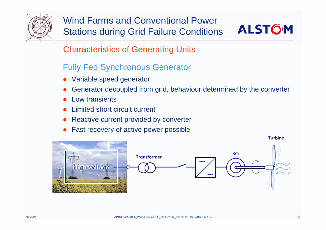
� Variable speed generator� Generator decoupled from grid, behaviour determined by the converter� Low transients� Limited short circuit current� Reactive current provided by converter� Fast recovery of active power possible
SG
Turbine
High voltageHigh voltage
Transformer ~~
Fully Fed Synchronous Generator
05.2004 APCG / 4MJA005_Wind-Farms-IEEE_13-05-2004_00EN.PPT/ Dr.JANSSEN / Be 9
Wind Farms and Conventional Power Stations during Grid Failure Conditions
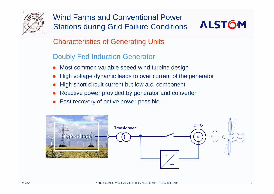
Characteristics of Generating Units
� Most common variable speed wind turbine design� High voltage dynamic leads to over current of the generator� High short circuit current but low a.c. component� Reactive power provided by generator and converter� Fast recovery of active power possible
DFIG
High voltageHigh voltage
Transformer
~~
Doubly Fed Induction Generator
05.2004 APCG / 4MJA005_Wind-Farms-IEEE_13-05-2004_00EN.PPT/ Dr.JANSSEN / Be 10
Wind Farms and Conventional Power Stations during Grid Failure Conditions
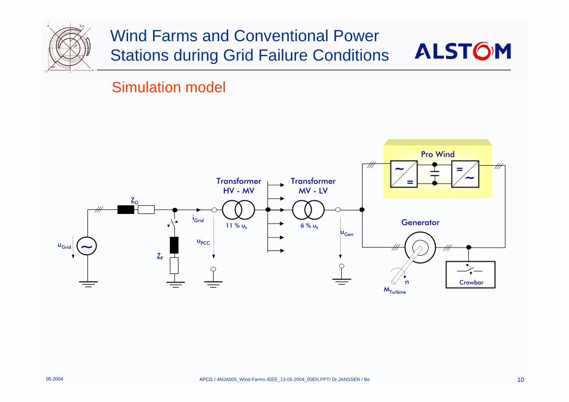
Simulation model
Pro Wind
=~ =
~
~
TransformerHV - MV
11 % uk
iGrid
uPCC
uGen
MTurbine
Crowbar
Generator
n
ZG
ZF
uGrid
TransformerMV - LV
6 % uk
05.2004 APCG / 4MJA005_Wind-Farms-IEEE_13-05-2004_00EN.PPT/ Dr.JANSSEN / Be 11
Wind Farms and Conventional Power Stations during Grid Failure Conditions
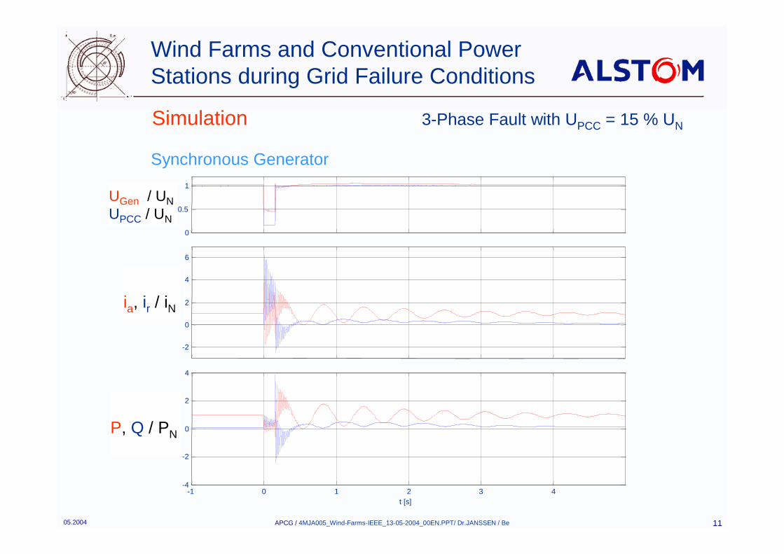
Simulation 3-Phase Fault with UPCC = 15 % UN
Synchronous Generator
0
0.5
1
U /
UN
-2
0
2
4
6
I Gri d
/ IN
-1 0 1 2 3 4-4
-2
0
2
4
P, Q
/ P
N
t [s]
ia, ir / iN
P, Q / PN
UGen / UNUPCC / UN

05.2004 APCG / 4MJA005_Wind-Farms-IEEE_13-05-2004_00EN.PPT/ Dr.JANSSEN / Be 12
Wind Farms and Conventional Power Stations during Grid Failure Conditions
Simulation 3-Phase Fault with UPCC = 15 % UN
0
0.5
1
U /
UN
-6
-4
-2
0
2
4
6
i Grid
/ iN
-0.1 0 0.1 0.2 0.3 0.4-4
-2
0
2
4
P, Q
/ P
N
t [s]
Synchronous Generator
UGen / UNUPCC / UN
P, Q / PN
iGrid / iN

05.2004 APCG / 4MJA005_Wind-Farms-IEEE_13-05-2004_00EN.PPT/ Dr.JANSSEN / Be 13
Wind Farms and Conventional Power Stations during Grid Failure Conditions
Simulation 3-Phase Fault with UPCC = 15 % UN
Fully Fed Synchronous Generator
0
0.5
1
U /
UN
-2
-1
0
1
2
i Gr id
/ iN
-1
0
1
2
I Grid
/ IN
-1 -0.9 -0.8 -0.7 -0.6 -0.5-1
0
1
2
P, Q
/ P
N
t [s]
UGen / UNUPCC / UN
iGrid / iN
P, Q / PN
ia, ir / iN
05.2004 APCG / 4MJA005_Wind-Farms-IEEE_13-05-2004_00EN.PPT/ Dr.JANSSEN / Be 14
Wind Farms and Conventional Power Stations during Grid Failure Conditions
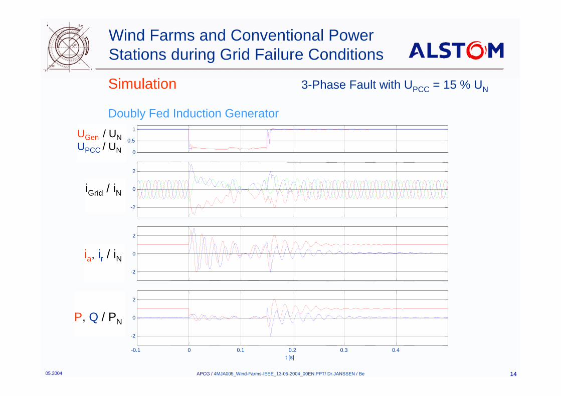
Simulation 3-Phase Fault with UPCC = 15 % UN
Doubly Fed Induction Generator
0
0.5
1
U /
UN
-2
0
2
i Gr id
/ iN
-2
0
2
I Grid
/ IN
-0.1 0 0.1 0.2 0.3 0.4
-2
0
2
P, Q
/ P
N
t [s]
UGen / UNUPCC / UN
iGrid / iN
P, Q / PN
ia, ir / iN
05.2004 APCG / 4MJA005_Wind-Farms-IEEE_13-05-2004_00EN.PPT/ Dr.JANSSEN / Be 15
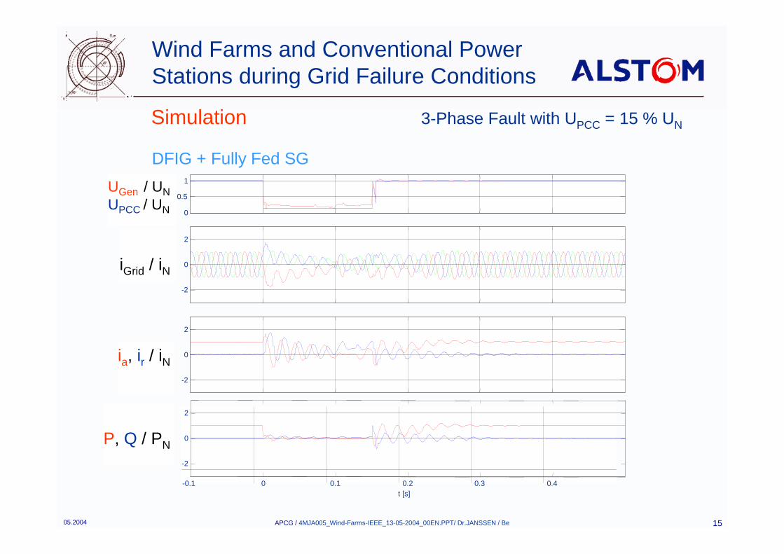
Wind Farms and Conventional Power Stations during Grid Failure Conditions
Simulation 3-Phase Fault with UPCC = 15 % UN
DFIG + Fully Fed SG
0
0.5
1
U /
UN
-2
0
2
i Gr id
/ iN
-2
0
2
I Grid
/ IN
-0.1 0 0.1 0.2 0.3 0.4
-2
0
2
P, Q
/ P
N
t [s]
UGen / UNUPCC / UN
iGrid / iN
P, Q / PN
ia, ir / iN
05.2004 APCG / 4MJA005_Wind-Farms-IEEE_13-05-2004_00EN.PPT/ Dr.JANSSEN / Be 16
Wind Farms and Conventional Power Stations during Grid Failure Conditions
Conclusion
� Wind farms can have a similar characteristic as conventional synchronous generators
� All types of generators have different advantages / drawbacks regarding short circuit current / reactive power / active power
� With an appropriate design and control wind farms can help to stabilize the grid

www.alstom.com