comparisons of shallow foundations in different soil · pdf filecomparisons of shallow...
TRANSCRIPT

International
OPEN ACCESS Journal
Of Modern Engineering Research (IJMER)
| IJMER | ISSN: 2249–6645 www.ijmer.com | Vol. 7 | Iss. 7 | July. 2017 | 37 |
Comparisons of Shallow Foundations in Different Soil Condition
*Jain Shrutika
1,Dr.Savita Maru
2
1Masters in Engineering Student, Department of Civil Engineering, UEC, jjain, Madhya Pradesh
2Professor, Department of Civil Engineering, UEC, Ujjain, M.P., India
Corresponding author: *Jain Shrutika
I. INTRODUCTION Foundation design involves a soil study to establish the most appropriate type of foundation and a
structural design to determine footing dimensions and required an amount of reinforcement. Because the
compressive strength of the soil is generally much weaker than that of the concrete, the contact area between the
soil and footing is much larger than that of the columns and walls. The soil is a universally available natural
material derived from rocks and rocky minerals. The bearing capacity of soil is the most important property
which governs the design of foundation. Soils are classified into three types: cohesive or fine grained soil, non-
cohesive or coarse grained soil and rocks.
Footings or foundation are structural elements, which transfer the load to the soil from column, walls or
lateral loads from earth retaining structures. The foundations are classified into two types, superficial foundation
or shallow foundation and deep foundation. A superficial foundation is a structural member whose cross section
is of large dimensions with respect to height and whose function is to transfer loads of a building at depths
relatively short, less than 4 m approximately with respect to the level of the surface of natural ground. Shallow
foundation includes: Wall Footing or Strip Footing, Isolated spread Footing, Combined Footing, Cantilever or
Strap Footing, Mat or raft Footing. If the soil conditions are weak then deep foundation are more suitable. The
deep foundation includes: Pile foundation, under reamed pile foundation and well foundation. The design of
foundation includes three major aspects i.e., stability, economy, and ease of construction. Stability analysis aims
at removing the possibility of failure of foundation by tilting, overturning, uprooting and sliding due to load
intensity imposed on soil by foundation being in excess of the ultimate capacity of the soil. The most important
aspect of the foundation design is the necessary check for the stability of foundation under various loads
imposed on it by the column, which it supports. The economy of the structure depends upon the material cost
and labor cost. Material cost mainly depends upon the quantity of steel and concrete whereas labor cost is
mainly depends on the shuttering cost and ease of construction. For the appropriate design of foundation these
three aspects should be satisfied. This paper explains the design of a shallow footing for different types like
square, rectangular, circular, trapezoid (sloped) and stepped footing for G+10 building with different types of
soil have different bearing capacities for middle side and corner column of the building. Results shows
comparison of depth of foundation, the quantity of steel required and quantity of concrete required with limit
state method.
For the foundation design, load analysis of G+10 multi-story residential building done on STADD pro.
The building is subjected to self-weight, dead load, live load as per IS 875(Part 1, Part 2):1987. Wind loads are
also considered on building as per Indian standard codes of practice IS 875(Part 3):1987. The wind loads on the
building are calculated assuming the building to be located at Ahmedabad. The member forces are calculated
ABSTRACT: Soil is considered by the engineer as a complex material produced by weathering of the
solid rock. Footings are structural elements that transmit column or wall loads to the underlying soil
below the structure. Footings are designed to transmit these loads to the soil without exceeding its safe
bearing capacity. Each building demands the need to solve a problem of foundation on different types of
soil. The main aim of this project is to design the appropriate foundation as per size and shape on
cohesive, non-cohesive and rocky soil. In this paper different foundation are studied for a middle side and
corner column of a building with different bearing capacities. Based on the study and judicial judgment
the type of foundation is decided as per depth, quantity of steel and quantity of concrete and try to find
which shape of the foundation is more stable, economical and ways to reduce the ease of construction of
the building.
Keywords: Isolated footing, Bearing capacity, depth, quantity of concrete and quantity of steel.

Comparisons Of Shallow Foundations In Different Soil Condition
| IJMER | ISSN: 2249–6645 www.ijmer.com | Vol. 7 | Iss. 7 | July. 2017 | 38 |
with load combinations for Limit State Method given in IS 456: 2000 and the foundations are designed for the
most critical middle column.
II. MODELING OF LOADS The basic loads considered in this study are dead load, live loads and wind loads. The values of Dead
loads (DL) are calculated from the unit weights as specified in IS 875 (Part 1): 1987. The live load (LL)
intensities for the various areas of residential buildings are obtained from IS 875 (Part 2): 1987. The summary of
dead load and live loads considered for the building is given in Table1
Table 1 Dead Load and Live Load Load Description Value
Dead Load
DL of Slab (Thickness of slab 0.125m)
Floor Finish
3.125 kN/m2
1 kN/m2
Wall load
100 mm thick interior wall
150 mm thick exterior wall
150 mm thick parapet wall
2.8 kN/m
4.2 kN /m
2.1 kN/m
Dead Load of Staircase
Load of inclined slab + load of riser, trade and landing
slab
6.715 kN/m2
Live Load
Live Load on slab
Live Load on stair
2 kN/m2 3 kN/m2
2.1 The Lateral Wind Force (Fz) as per IS875 (Part 3):1987
According to the provisions of Bureau of Indian Standards for wind loads, IS 875 (Part 3):1987 design
wind speed, Vz at any height z is found by equation,
Vz = Vb k1 k2 k3
where, Vb is basic wind speed in m/s, k1 is probability factor (risk coefficient) as per Clause 5.3.1, k2 is
terrain, height and structure size factor as per Clause 5.3.2 and k3 is topography factor as per Clause 5.3.3. The
lateral force along wind load on a structure on a strip area (Ae) at any height, z is found by equation
Fz= Cf Ae Pz
Where, Cf is force coefficient for building, calculated from clause no 6.3.3.2(fig.4A). As per clause for
flat-sided member, the force coefficients are calculated for two mutually perpendicular directions relative to a
reference axis on the structural member. They are designated as Cfn and Cft, give the forces normal and
transverse, respectively to the reference plane Normal force, Fn = Cfn Pz Ae Transverse force, Ft = Cft Pz Ae , Ae is
effective frontal area considered for the structure at height z, Pz is design pressure at height, z found by equation
Pz = 0.6 Vz2(N/m2)
The data considered for the wind load calculations are wind speed, Vb=39m/s, force coefficient, Cf
=1.3, K1=1.0, K2 is varying with height as per Terrain Category III class A, K3=1, Life of the structure is 50
years, the lateral force Fz is considered in kN/m and these wind intensities at various heights are given as input
to the STAAD.Pro software as given in Table 2 and Table 3
Table 2 Wind Force At Various Heights In Normal Z Direction
Height
(m) Vb(m/s) k1 k2 k3 Vz(m/sec)
Pz
(kN/m2) Cf
Ae
(m2)
Force on
end
column (kN/m)
Force
on middle
Column
(kN/m)
3.05 39 1 0.91 1 35.49 0.76 1.3 52.46 3.38 6.76
6.1 39 1 0.91 1 35.49 0.76 1.3 52.46 3.38 6.76
9.15 39 1 0.91 1 35.49 0.76 1.3 52.46 3.38 6.76
12.2 39 1 0.94 1 36.66 0.81 1.3 52.46 3.61 7.21
15.25 39 1 0.97 1 37.83 0.86 1.3 52.46 3.84 7.68

Comparisons Of Shallow Foundations In Different Soil Condition
| IJMER | ISSN: 2249–6645 www.ijmer.com | Vol. 7 | Iss. 7 | July. 2017 | 39 |
18.3 39 1 1 1 39 0.91 1.3 52.46 4.08 8.16
21.35 39 1 1.02 1 39.78 0.95 1.3 52.46 4.25 8.49
24.4 39 1 1.03 1 40.17 0.97 1.3 52.46 4.33 8.66
27.45 39 1 1.05 1 40.95 1.01 1.3 52.46 4.50 9.00
30.5 39 1 1.06 1 41.34 1.03 1.3 52.46 4.59 9.17
33.55 39 1 1.07 1 41.73 1.04 1.3 52.46 4.67 9.35
TABLE 3 Wind force at various heights in transverse X direction
Height (m)
Vb(m/s) k1 k2 k3 Vz (m/sec) Pz
(kN/m2) Cf
Ae
(m2)
Force on
end column
(kN/m)
Force on
middle Column
(kN/m)
3.05 39 1 0.91 1 35.49 0.76 1.3 33.86 2.73 5.45
6.1 39 1 0.91 1 35.49 0.76 1.3 33.86 2.73 5.45
9.15 39 1 0.91 1 35.49 0.76 1.3 33.86 2.73 5.45
12.2 39 1 0.94 1 36.66 0.81 1.3 33.86 2.91 5.82
15.25 39 1 0.97 1 37.83 0.86 1.3 33.86 3.10 6.20
18.3 39 1 1 1 39 0.91 1.3 33.86 3.29 6.59
21.35 39 1 1.02 1 39.78 0.95 1.3 33.86 3.43 6.85
24.4 39 1 1.03 1 40.17 0.97 1.3 33.86 3.49 6.99
27.45 39 1 1.05 1 40.95 1.01 1.3 33.86 3.63 7.26
30.5 39 1 1.06 1 41.34 1.03 1.3 33.86 3.70 7.40
33.55 39 1 1.07 1 41.73 1.04 1.3 33.86 3.77 7.54
2.2 Load Combinations
The variation in loads due to unforeseen increases in loads, constructional inaccuracies, type of limit
state etc. are taken into account to define the design load. The design load is given by: design load = ϒfx
characteristic load (Clause 36.4 of IS 456: 2000). Where, ϒf given Partial safety for loads for loads given in
Table18 of IS 456: 2000 is given in Table 4.
TABLE 4 Partial safety factor (ϒf )for loads (According to IS 456: 2000)
Load combination Limit state of collapse Limit state of serviceability
DL IL WL DL IL WL
DL + IL 1.5 1.5 - 1.0 1.0 -
DL+ WL 1.5 or 0.9* - 1.5 1.0 - 1.0
DL+ IL + WL 1.2 1.2 1.2 1.0 0.8 0.8
Notes: (*) This value is to be considered when stability against overturning or stress reversal is critical.
1. DL = Dead load; IL = Imposed load or Live load; WL = Wind load 2. While considering earthquake effects, substitute EL for WL
3. For the limit states of serviceability, the values of given in this table are applicable for short tern effects. While assessing
the long term effects due to creep the dead load and that part of the live load likely to be permanent may only be considered.
III. DESIGN OF FOUNDATION Table 5 Building Model
Beam size 200 mm x 250 mm
Rectangular column size 200 mm x 450 mm
Rectangular column size 300 mm x 450 mm
Square column size 400 mm x 400 mm
Circular Column size 450 mm
Height of story 3.05 m
Figure from AutoCAD 2013

Comparisons Of Shallow Foundations In Different Soil Condition
| IJMER | ISSN: 2249–6645 www.ijmer.com | Vol. 7 | Iss. 7 | July. 2017 | 40 |
Fig. 1 Centre line plan for the columns of a building
For designing purpose of different shapes of footing under this load square and circular column are
assumed in place of rectangular column in STADD model. From STADD results middle column no 48, side
column no. 47 and corner column no. 50 has maximum critical load of 2681 kN, 1639 kN and 1518kN. For
comparisons of result same load is required, for calculation purpose ± 1 ton of load due to shape of column is
done on all shapes of columns load. Average loads for calculation is 2691 kN for middle column, 1650 kN for
side column and 1530 kN for corner column. Now design of square, rectangular and circular footing done on
these columns for 100kN/m2, 180kN/m2 and 250kN/m2 bearing capacities and also study the effect of
geometry on all shapes by designing of stepped and sloped (trapezoid) footing for square, rectangular and
circular column. Results of design are shown below
3.1 Middle Column Foundation Design
Square Footing: Result of plain, trapezoid and stepped footing design shown in Table 6, Table 7and Table 8.
TABLE 6 Square plain footing design Bearing Capacities of soil in kN/ m2 100 kN/m2 180 kN/m2 250 kN/m2
Size of Footing in m 5.6 x 5.6 4.2 x 4.2 3.6 x 3.6
Depth in m 0.62 0. 62 0.70
Bending Moment in kNm 1608.88 1159.89 958.46
Permissible shear stress in N/mm2 1.17 1.17 0.89
Area of steel in m2 8265.80 6003.99 4217.94
No. of bars of tor steel 16mm dia bars 41 no. 16mm dia bars 30 no. 16mm dia bars 21 no.
Spacing in mm c/c 136 141 172
Provided Area of Steel in m2 8266 6004 4218
Length of bar in m 5.5 4.1 3.5
Total length of bar in m 452 245 147
Weight of bar per m 1.581 1.581 1.581
Quantity of steel in tonn 0.72 0.39 0.23
Quantity of concrete in m3 19.44 10.85 9.12
Comparisons Of Shallow Foundations In Different Soil Condition
| IJMER | ISSN: 2249–6645 www.ijmer.com | Vol. 7 | Iss. 7 | July. 2017 | 41 |
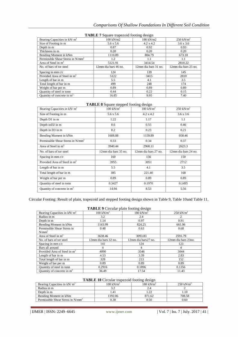
TABLE 7 Square trapezoid footing design Bearing Capacities in kN/ m2 100 kN/m2 180 kN/m2 250 kN/m2
Size of Footing in m 5.6 x 5.6 4.2 x 4.2 3.6 x 3.6
Depth in m 0.87 0.92 0.93
Thickness in m 0.20 0.20 0.20
Bending Moment in kNm 1110.89 804.79 673.18
Permissible Shear Stress in N/mm2 1.2 1.1 1.1
Area of Steel in m2 5121.91 3414.54 2810.22
No. of bars of tor steel 12mm dia bars 46 no. 12mm dia bars 31 no. 12mm dia bars 25 no.
Spacing in mm c/c 124 139 145
Provided Area of Steel in m2 5122 3415 2810
Length of bar in m 5.5 4.1 3.5
Total length of bar in m 499 248 174
Weight of bar per m 0.89 0.89 0.89
Quantity of steel in tonn 0.44 0.22 0.15
Quantity of concrete in m3 16.85 9.95 7.40
TABLE 8 Square stepped footing design Bearing Capacities in kN/ m2 100 kN/m2 180 kN/m2 250 kN/m2
Size of Footing in m 5.6 x 5.6 4.2 x 4.2 3.6 x 3.6
Depth D1 in m 1.22 1.17 1.1
Depth inD2 in m 0.6 0.55 0.46
Depth in D3 in m 0.2 0.23 0.21
Bending Moment in kNm 1608.88 1159.89 958.46
Permissible Shear Stress in N/mm2 0.33 0.34 0.37
Area of Steel in m2 3940.44 2968.11 2623.3
No. of bars of tor steel 12mm dia bars 35 no. 12mm dia bars 27 no. 12mm dia bars 24 no.
Spacing in mm c/c 160 156 150
Provided Area of Steel in m2 3955 3051 2712
Length of bar in m 5.5 4.1 3.5
Total length of bar in m 385 221.40 168
Weight of bar per m 0.89 0.89 0.89
Quantity of steel in tonn 0.3427 0.1970 0.1495
Quantity of concrete in m3 14.94 8.53 5.56
Circular Footing: Result of plain, trapezoid and stepped footing design shown in Table 9, Table 10and Table 11.
TABLE 9 Circular plain footing design Bearing Capacities in kN/ m2 100 kN/m2 180 kN/m2 250 kN/m2
Radius in m 3.2 2.4 2
Depth in m 1.14 0.97 0.91
Bending Moment in kNm 1143.99 824.25 661.96
Permissible Shear Stress in
N/mm2
0.48 0.63 0.68
Area of Steel in m2 3638.46 3093.83 2591.79
No. of bars of tor steel 12mm dia bars 32 no. 12mm dia bars27 no. 12mm dia bars 23no.
Spacing in mm c/c 141 124 123
Bars all around 4 4 4
Provided Area of Steel in m2 4090 3546 3044
Length of bar in m 4.53 3.39 2.83
Total length of bar in m 328 213 152
Weight of bar per m 0.89 0.89 0.89
Quantity of steel in tonn 0.2916 0.1896 0.1356
Quantity of concrete in m3 36.49 17.54 11.43
TABLE 10 Circular trapezoid footing design Bearing Capacities in kN/ m2 100 kN/m2 180 kN/m2 250 kN/m2
Radius in m 3.2 2.4 2
Depth in m 1.41 1.22 1.10
Bending Moment in kNm 1192.06 871.62 708.58
Permissible Shear Stress in N/mm2 0.38 0.50 0.60

Comparisons Of Shallow Foundations In Different Soil Condition
| IJMER | ISSN: 2249–6645 www.ijmer.com | Vol. 7 | Iss. 7 | July. 2017 | 42 |
Area of Steel in m2 3019.64 2556.64 2322.79
No. of bars of tor steel 12mm dia bars 27 no. 12mm dia bars 23 no. 12mm dia bars 21no.
Spacing in mm c/c 169 150 138
Bars all around 4 4 4
Provided Area of Steel in m2 3472 2557 2323
Length of bar in m 4.53 3.39 2.83
Total length of bar in m 278 181 139
Weight of bar per m 0.89 0.89 0.89
Quantity of steel in tonn 0.2475 0.1609 0.1236
Quantity of concrete in m3 45.34 22.07 13.82
TABLE 11 Circular stepped footing design Bearing Capacities in kN/ m2 100 kN/m2 180 kN/m2 250 kN/m2
Radius in m 3.2 2.4 2
Depth D1 in m 1.14 0.97 0.88
Depth D2 in m 0.55 0.50 0.50
Depth D3 in m 0.40 0.44 0.45
Bending Moment in kNm 1140.04 819.10 655.93
Permissible in N/mm2 0.48 0.63 0.73
Area of Steel in m2 3594.63 3068.25 2709.46
No. of bars of tor steel 12mm dia bars 32 no. 12mm dia bars 27no. 12mm dia bars 24 no.
Spacing in mm c/c 126 109 101
Bars all around 4 4 4
Provided Area of Steel in m2 4047 3520 3161
Length of bar 4.53 3.39 2.83
Total length of bar 324 211 158
Weight of bar per m 0.89 0.89 0.89
Quantity of steel in tonn 0.2885 0.1882 0.1409
Quantity of concrete in m3 17.88 9.31 6.75
Rectangular Footing: Result of plain, trapezoid and stepped footing design shown in Table 12, Table 13, Table
14
Table 12 Rectangular plain footing design Bearing Capacities in kN/ m2 100 kN/m2 180 kN/m2 250 kN/m2
Size of Footing in m 4.6 x 6.8 3.4 x 5.1 2.9 x 4.4
Depth in m 0.82 0.82 0.90
Bending Moment in kNm 1993.95 1424.38 1187.74
Permissible Shear Stress in N/mm2 1.09 1.05 0.82
Area of Steel in m2(Y-Y) 7176.14 5126.29 3872.28
Area of Steel in m2(X-X) 4961.79 3481.43 2582.42
Balance steel 957.54 667.43 371.42
No. of bars of tor steel (Y-Y) 16mm dia bars 36 no. 16mm dia bars 26 no. 16mm dia bars 19 no.
No. of bars of tor steel (X-X) 12mm dia bars 36 no. 12mm dia bars 25 no. 12mm dia bars 20 no.
No. of bars in balance steel at corner 10 6 6
Spacing in m c/c (Y-Y) 129 131 151
Spacing in m c/c (X-X) 128 136 145
Provided Area of Steel in m2(X-X) 7176 5226 3872
Provided Area of Steel in m2(Y-Y) 4068 2825 2260
Length of bar (L) in m 161 86 54
Length of bar (B) in m 241 125 88
Length of bar of balance steel in m 45 20 17
Weight of bar per m 1.5815 1.5815 1.5815
Weight of bar per m 0.89 0.89 0.89
Quantity of steel in tonn (Y-Y) 0.3253 0.1670 0.1119
Quantity of steel in tonn (X-X) 0.2147 0.1113 0.0783
Total quantity of steel in tonn 0.5399 0.2783 0.1902
Quantity of concrete in m3 25.65 14.22 11.48
Comparisons Of Shallow Foundations In Different Soil Condition
| IJMER | ISSN: 2249–6645 www.ijmer.com | Vol. 7 | Iss. 7 | July. 2017 | 43 |
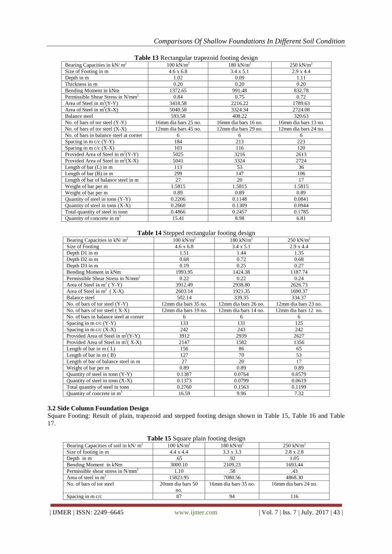
Table 13 Rectangular trapezoid footing design Bearing Capacities in kN/ m2 100 kN/m2 180 kN/m2 250 kN/m2
Size of Footing in m 4.6 x 6.8 3.4 x 5.1 2.9 x 4.4
Depth in m 1.02 0.09 1.11
Thickness in m 0.20 0.20 0.20
Bending Moment in kNm 1372.65 991.48 832.78
Permissible Shear Stress in N/mm2 0.84 0.75 0.72
Area of Steel in m2(Y-Y) 3418.58 2216.22 1789.63
Area of Steel in m2(X-X) 5040.58 3324.34 2724.08
Balance steel 593.58 408.22 320.63
No. of bars of tor steel (Y-Y) 16mm dia bars 25 no. 16mm dia bars 16 no. 16mm dia bars 13 no.
No. of bars of tor steel (X-X) 12mm dia bars 45 no. 12mm dia bars 29 no. 12mm dia bars 24 no.
No. of bars in balance steel at corner 6 6 6
Spacing in m c/c (Y-Y) 184 213 223
Spacing in m c/c (X-X) 103 116 120
Provided Area of Steel in m2(Y-Y) 5025 3216 2613
Provided Area of Steel in m2(X-X) 5041 3324 2724
Length of bar (L) in m 113 53 36
Length of bar (B) in m 299 147 106
Length of bar of balance steel in m 27 20 17
Weight of bar per m 1.5815 1.5815 1.5815
Weight of bar per m 0.89 0.89 0.89
Quantity of steel in tonn (Y-Y) 0.2206 0.1148 0.0841
Quantity of steel in tonn (X-X) 0.2660 0.1309 0.0944
Total quantity of steel in tonn 0.4866 0.2457 0.1785
Quantity of concrete in m3 15.41 8.98 6.81
Table 14 Stepped rectangular footing design Bearing Capacities in kN/ m2 100 kN/m2 180 kN/m2 250 kN/m2
Size of Footing 4.6 x 6.8 3.4 x 5.1 2.9 x 4.4
Depth D1 in m 1.51 1.44 1.35
Depth D2 in m 0.68 0.72 0.68
Depth D3 in m 0.19 0.25 0.27
Bending Moment in kNm 1993.95 1424.38 1187.74
Permissible Shear Stress in N/mm2 0.22 0.22 0.24
Area of Steel in m2 ( Y-Y) 3912.49 2938.80 2626.73
Area of Steel in m2 ( X-X) 2603.14 1921.35 1690.37
Balance steel 502.14 339.35 334.37
No. of bars of tor steel (Y-Y) 12mm dia bars 35 no. 12mm dia bars 26 no. 12mm dia bars 23 no.
No. of bars of tor steel ( X-X) 12mm dia bars 19 no. 12mm dia bars 14 no. 12mm dia bars 12 no.
No. of bars in balance steel at corner 6 6 6
Spacing in m c/c (Y-Y) 133 131 125
Spacing in m c/c (X-X) 242 243 242
Provided Area of Steel in m2(Y-Y) 3912 2939 2627
Provided Area of Steel in m2( X-X) 2147 1582 1356
Length of bar in m ( L) 156 86 65
Length of bar in m ( B) 127 70 53
Length of bar of balance steel in m 27 20 17
Weight of bar per m 0.89 0.89 0.89
Quantity of steel in tonn (Y-Y) 0.1387 0.0764 0.0579
Quantity of steel in tonn (X-X) 0.1373 0.0799 0.0619
Total quantity of steel in tonn 0.2760 0.1563 0.1199
Quantity of concrete in m3 16.59 9.96 7.32
3.2 Side Column Foundation Design
Square Footing: Result of plain, trapezoid and stepped footing design shown in Table 15, Table 16 and Table
17.
Table 15 Square plain footing design Bearing Capacities of soil in kN/ m2 100 kN/m2 180 kN/m2 250 kN/m2
Size of footing in m 4.4 x 4.4 3.3 x 3.3 2.8 x 2.8
Depth in m .65 .92 1.05
Bending Moment in kNm 3000.10 2109.23 1693.44
Permissible shear stress in N/mm2 1.10 .58 .43
Area of steel in m2 15823.95 7080.56 4868.30
No. of bars of tor steel 20mm dia bars 50
no.
16mm dia bars 35 no. 16mm dia bars 24 no.
Spacing in m c/c 87 94 116

Comparisons Of Shallow Foundations In Different Soil Condition
| IJMER | ISSN: 2249–6645 www.ijmer.com | Vol. 7 | Iss. 7 | July. 2017 | 44 |
Provided Area of Steel in m2 15823.95 7080.56 4868.30
Length of bar in m 4.3 3.2 2.7
Total length of bar in m 433 225 131
Weight of bar per m 2.46 1.5815 1.5815
Quantity of steel in tonn 1.0662 0.3566 0.2068
Quantity of concrete in m3 12.58 10.02 8.23
Table 16 Square trapezoid footing design Bearing Capacities in kN/ m2 100 kN/m2 180 kN/m2 250 kN/m2
Size of footing in m 4.4 x 4.4 3.3 x 3.3 2.8 x 2.8
Depth in m 0.95 1.09 1.09
Thickness in m 0.2 0.2 0.2
Bending Moment in kNm 522.74 372.84 302.4
Permissible Shear Stress in N/mm2 0.44 0.35 0.34
Area of Steel in m2 6671.29 4074.13 3300.61
No. of bars of tor steel 16mm dia bars 33 no. 16mm dia bars 20 no. 16mm dia bars16 no.
Spacing in m c/c 133 163 171
Provided Area of Steel in m2 6671 4074 3300
Length of bar in m 4.3 3.2 2.7
Total length of bar in m 285 130 89
Weight of bar per m 1.5815 1.5815 1.5815
Quantity of steel in tonn 0.4514 0.2052 0.1402
Quantity of concrete in m3 6.73 4.49 3.3
Table 17 Square stepped footing design Bearing Capacities in kN/ m2 100 kN/m2 180 kN/m2 250 kN/m2
Size of footing in m 4.4 x 4.4 3.3 x 3.3 2.8 x 2.8
Depth D1 in m 1.84 1.72 1.60
Depth D2 in m 0.9 0.91 0.89
Depth D3 in m 0.6 0.55 0.53
Bending Moment in kNm 3000.10 2109.23 1693.44
Permissible Shear Stress in N/mm2 0.16 0.17 0.17
Area of Steel in m2 4702.69 3547.29 3072.67
No. of bars of tor steel 16mm dia bars 23 no. 16mm dia bars 18 no. 16mm dia bars 15 no.
Spacing in m c/c 188 187 183
Provided Area of Steel in m2 4703 3547 3073
Length of bar in m 4.3 3.2 2.7
Total length of bar in m 201 113 83
Weight of bar per m 1.5815 1.5815 1.5815
Quantity of steel in tonn 0.3182 0.1786 0.1306
Quantity of concrete in m3 17.03 9.42 6.61
Rectangular Footing: Result of plain, trapezoid and stepped footing design shown in Table 18, Table 19 and
Table 20.
Table 18 Rectangular plain footing design Bearing Capacities in kN/ m2 100 kN/m2 180 kN/m2 250 kN/m2
Size of footing in m 5.4 x 3.6 4 x 2.7 3.4 x 2.3
Depth in m 0.89 1.10 1.08
Bending Moment in kNm 2499.26 1762.56 1434.80
Permissible Shear Stress in N/mm2 0.69 0.44 0.44
Area of Steel in m2(Y-Y) 8772.93 4821.79 4000.31
Area of Steel in m2(X-X) 3136.82 1732.27 1432.45
Balance steel 627.37 263.27 189.45
No. of bars of tor steel (Y-Y) 16mm dia bars 44 no. 16mm dia bars 24 no. 16mm dia bars 20 no.
No .of bars of tor steel (X-X) 12mm dia bars 23 no. 12mm dia bars 13 no. 12mm dia bars 11 no.
No. of bars in balance steel at corner 6 6 6
Spacing in m c/c (Y-Y) 82 113 116
Spacing in m c/c ( X-X) 157 208 209
Provided Area of Steel in m2(Y-Y) 8773 4822 4000
Provided Area of Steel in m2(X-X) 3277 2147 1921
Length of bar (L) in m 3.5 2.6 2.2
Length of bar (B) in m 5.3 3.9 3.3
Total length of bar in m (Y-Y) 153 62 44
Total length of bar in m (X-X) 154 74 56
Weight of bar per m 1.5815 1.5815 1.5815
Weight of bar per m 0.89 0.89 0.89
Quantity of steel in tonn (Y-Y) 0.1368 0.0659 0.0499
Comparisons Of Shallow Foundations In Different Soil Condition
| IJMER | ISSN: 2249–6645 www.ijmer.com | Vol. 7 | Iss. 7 | July. 2017 | 45 |
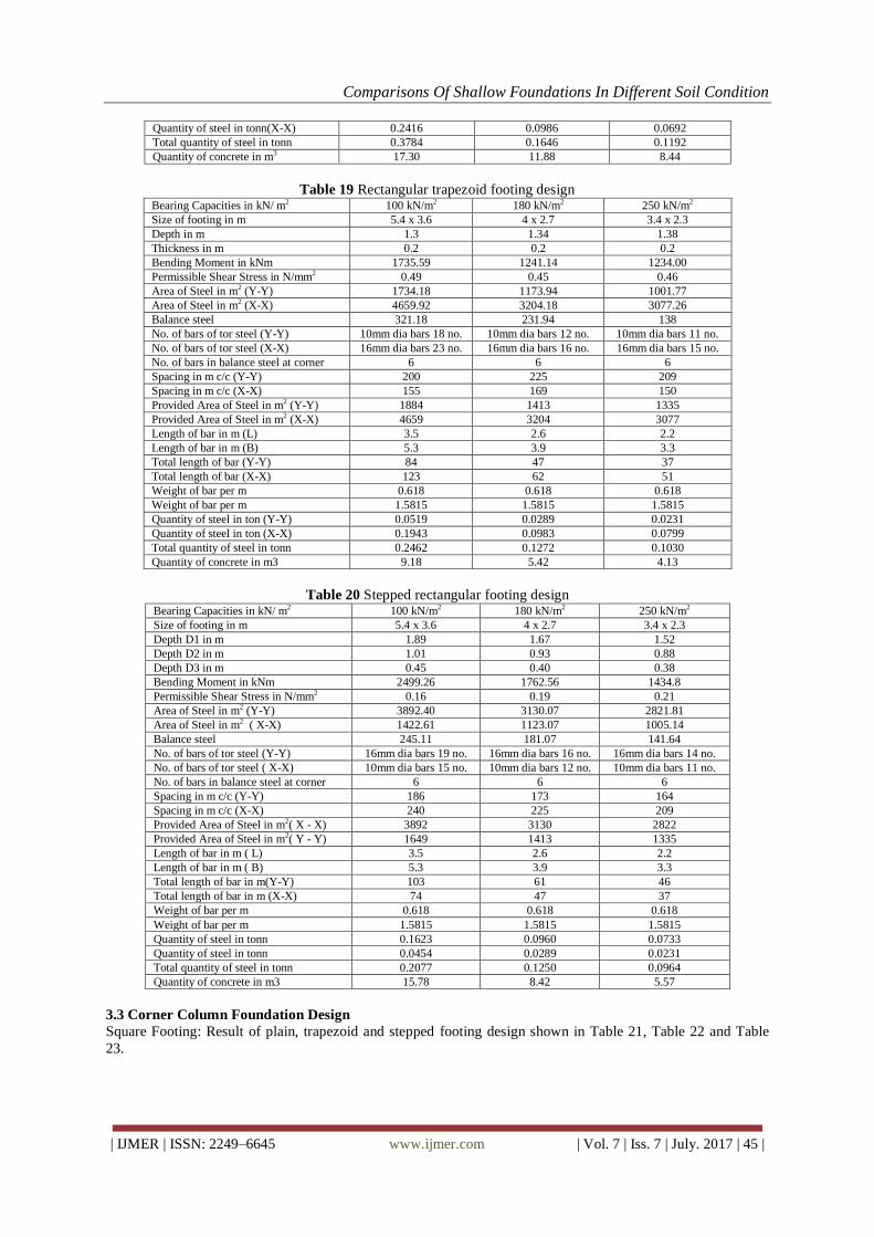
Quantity of steel in tonn(X-X) 0.2416 0.0986 0.0692
Total quantity of steel in tonn 0.3784 0.1646 0.1192
Quantity of concrete in m3 17.30 11.88 8.44
Table 19 Rectangular trapezoid footing design Bearing Capacities in kN/ m2 100 kN/m2 180 kN/m2 250 kN/m2
Size of footing in m 5.4 x 3.6 4 x 2.7 3.4 x 2.3
Depth in m 1.3 1.34 1.38
Thickness in m 0.2 0.2 0.2
Bending Moment in kNm 1735.59 1241.14 1234.00
Permissible Shear Stress in N/mm2 0.49 0.45 0.46
Area of Steel in m2 (Y-Y) 1734.18 1173.94 1001.77
Area of Steel in m2 (X-X) 4659.92 3204.18 3077.26
Balance steel 321.18 231.94 138
No. of bars of tor steel (Y-Y) 10mm dia bars 18 no. 10mm dia bars 12 no. 10mm dia bars 11 no.
No. of bars of tor steel (X-X) 16mm dia bars 23 no. 16mm dia bars 16 no. 16mm dia bars 15 no.
No. of bars in balance steel at corner 6 6 6
Spacing in m c/c (Y-Y) 200 225 209
Spacing in m c/c (X-X) 155 169 150
Provided Area of Steel in m2 (Y-Y) 1884 1413 1335
Provided Area of Steel in m2 (X-X) 4659 3204 3077
Length of bar in m (L) 3.5 2.6 2.2
Length of bar in m (B) 5.3 3.9 3.3
Total length of bar (Y-Y) 84 47 37
Total length of bar (X-X) 123 62 51
Weight of bar per m 0.618 0.618 0.618
Weight of bar per m 1.5815 1.5815 1.5815
Quantity of steel in ton (Y-Y) 0.0519 0.0289 0.0231
Quantity of steel in ton (X-X) 0.1943 0.0983 0.0799
Total quantity of steel in tonn 0.2462 0.1272 0.1030
Quantity of concrete in m3 9.18 5.42 4.13
Table 20 Stepped rectangular footing design Bearing Capacities in kN/ m2 100 kN/m2 180 kN/m2 250 kN/m2
Size of footing in m 5.4 x 3.6 4 x 2.7 3.4 x 2.3
Depth D1 in m 1.89 1.67 1.52
Depth D2 in m 1.01 0.93 0.88
Depth D3 in m 0.45 0.40 0.38
Bending Moment in kNm 2499.26 1762.56 1434.8
Permissible Shear Stress in N/mm2 0.16 0.19 0.21
Area of Steel in m2 (Y-Y) 3892.40 3130.07 2821.81
Area of Steel in m2 ( X-X) 1422.61 1123.07 1005.14
Balance steel 245.11 181.07 141.64
No. of bars of tor steel (Y-Y) 16mm dia bars 19 no. 16mm dia bars 16 no. 16mm dia bars 14 no.
No. of bars of tor steel ( X-X) 10mm dia bars 15 no. 10mm dia bars 12 no. 10mm dia bars 11 no.
No. of bars in balance steel at corner 6 6 6
Spacing in m c/c (Y-Y) 186 173 164
Spacing in m c/c (X-X) 240 225 209
Provided Area of Steel in m2( X - X) 3892 3130 2822
Provided Area of Steel in m2( Y - Y) 1649 1413 1335
Length of bar in m ( L) 3.5 2.6 2.2
Length of bar in m ( B) 5.3 3.9 3.3
Total length of bar in m(Y-Y) 103 61 46
Total length of bar in m (X-X) 74 47 37
Weight of bar per m 0.618 0.618 0.618
Weight of bar per m 1.5815 1.5815 1.5815
Quantity of steel in tonn 0.1623 0.0960 0.0733
Quantity of steel in tonn 0.0454 0.0289 0.0231
Total quantity of steel in tonn 0.2077 0.1250 0.0964
Quantity of concrete in m3 15.78 8.42 5.57
3.3 Corner Column Foundation Design
Square Footing: Result of plain, trapezoid and stepped footing design shown in Table 21, Table 22 and Table
23.

Comparisons Of Shallow Foundations In Different Soil Condition
| IJMER | ISSN: 2249–6645 www.ijmer.com | Vol. 7 | Iss. 7 | July. 2017 | 46 |
Table 21 Square plain footing design Bearing Capacities of soil in kN/ m2 100 kN/m2 180 kN/m2 250 kN/m2
Size of Footing in m 4.3 x 4.3 3.2 x 3.2 2.7 x 2.7
Depth in m 0.87 0.88 1.01
Bending Moment in kNm 2704.41 1869.06 1499.72
Permissible shear stress in N/mm2 1.08 1.01 0.74
Area of steel in m2 9692.01 6578.20 4490.42
No. of bars of tor steel 16mm dia bars 48 no. 16mm dia bars 33 no. 16mm dia bars 22 no.
Spacing in mm c/c 90 100 120
Provided Area of Steel in m2 9692.013 6578.203 4490.416
Length of bar in m 4.2 3.1 2.6
Total length of bar in m 405 203 116
Weight of bar per m 1.5815 1.5815 1.5815
Quantity of steel in tonn 0.6406 0.3209 0.1837
Quantity of concrete in m3 16.09 9.01 7.36
Table 22 Square trapezoid footing design Bearing Capacities in kN/ m2
100 kN/m2 180 kN/m2 250 kN/m2
Size of Footing in m 4.3 x 4.3 3.2 x 3.2 2.7 x 2.7
Depth in m 1.26 1.27 1.28
Thickness in m 0.2 0.2 0.2
Bending Moment in kNm 1886.80 1323.91 1073.87
Permissible Shear Stress in N/mm2
1.10 1.11 1.11
Area of Steel in m2 5311.51 3682.98 2954.23
No. of bars of tor steel 16mm dia bars 26 no. 16mm dia bars 18 no. 16mm dia bars 15 no.
Spacing in mm c/c 165 175 185
Provided Area of Steel in m2 5311.51 3682.97 2954.23
Length of bar in m 4.2 3.1 2.6
Total length of bar in m 222 114 76
Weight of bar per m 1.5815 1.5815 1.5815
Quantity of steel in tonn 0.3511 0.1797 0.1209
Quantity of concrete in m3 8.55 4.94 3.64
Table 23 Square stepped Footing design Bearing Capacities in kN/ m2 100 kN/m2 180 kN/m2 250 kN/m2
Size of Footing in m 4.3 x 4.3 3.2 x 3.2 2.7 x 2.7
Depth D1 in m 1.81 1.64 1.53
Depth D2 in m 0.84 0.87 0.85
Depth D3 in m 0.25 0.30 0.31
Bending Moment in kNm 2836.20 1869.06 1499..72
Permissible Shear Stress in N/mm2 0.32 0.35 0.37
Area of Steel in m2 4521.60 3301.89 2850.18
No. of bars of tor bar 16mm dia bars 22 no. 16mm dia bars 16 no. 16mm dia bars 14 no.
Spacing in mm c/c 190 190 185
Provided Area of Steel in m2 4521.56 3301.90 2850.18
Length of bar in m 4.2 3.1 2.6
Total length of bar in m 189 102 74
Weight of bar per m 1.5815 1.5815 1.5815
Quantity of steel in tonn 0.2988 0.1611 0.1166
Quantity of concrete in m3 11.92 7.4 5.2
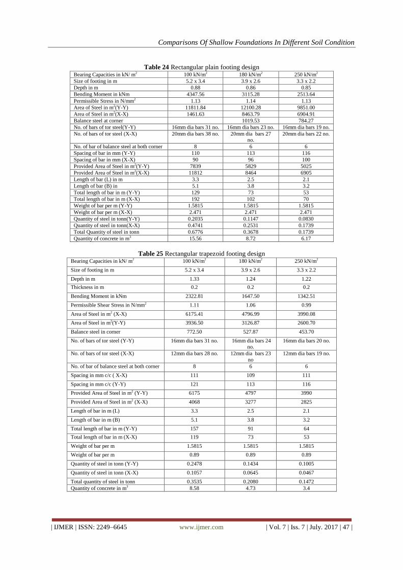
Rectangular Footing: Result of plain, trapezoid and stepped footing design shown in Table 24, Table 25 and
Table 26.
Comparisons Of Shallow Foundations In Different Soil Condition
| IJMER | ISSN: 2249–6645 www.ijmer.com | Vol. 7 | Iss. 7 | July. 2017 | 47 |
Table 24 Rectangular plain footing design Bearing Capacities in kN/ m2 100 kN/m2 180 kN/m2 250 kN/m2
Size of footing in m 5.2 x 3.4 3.9 x 2.6 3.3 x 2.2
Depth in m 0.88 0.86 0.85
Bending Moment in kNm 4347.56 3115.28 2513.64
Permissible Stress in N/mm2 1.13 1.14 1.13
Area of Steel in m2(Y-Y) 11811.84 12100.28 9851.00
Area of Steel in m2(X-X) 1461.63 8463.79 6904.91
Balance steel at corner 1019.53 784.27
No. of bars of tor steel(Y-Y) 16mm dia bars 31 no. 16mm dia bars 23 no. 16mm dia bars 19 no.
No. of bars of tor steel (X-X) 20mm dia bars 38 no. 20mm dia bars 27 no.
20mm dia bars 22 no.
No. of bar of balance steel at both corner 8 6 6
Spacing of bar in mm (Y-Y) 110 113 116
Spacing of bar in mm (X-X) 90 96 100
Provided Area of Steel in m2(Y-Y) 7839 5829 5025
Provided Area of Steel in m2(X-X) 11812 8464 6905
Length of bar (L) in m 3.3 2.5 2.1
Length of bar (B) in 5.1 3.8 3.2
Total length of bar in m (Y-Y) 129 73 53
Total length of bar in m (X-X) 192 102 70
Weight of bar per m (Y-Y) 1.5815 1.5815 1.5815
Weight of bar per m (X-X) 2.471 2.471 2.471
Quantity of steel in tonn(Y-Y) 0.2035 0.1147 0.0830
Quantity of steel in tonn(X-X) 0.4741 0.2531 0.1739
Total Quantity of steel in tonn 0.6776 0.3678 0.1739
Quantity of concrete in m3 15.56 8.72 6.17
Table 25 Rectangular trapezoid footing design Bearing Capacities in kN/ m2 100 kN/m2 180 kN/m2 250 kN/m2
Size of footing in m 5.2 x 3.4 3.9 x 2.6 3.3 x 2.2
Depth in m 1.33 1.24 1.22
Thickness in m 0.2 0.2 0.2
Bending Moment in kNm 2322.81 1647.50 1342.51
Permissible Shear Stress in N/mm2 1.11 1.06 0.99
Area of Steel in m2 (X-X) 6175.41 4796.99 3990.08
Area of Steel in m2(Y-Y) 3936.50 3126.87 2600.70
Balance steel in corner 772.50 527.87 453.70
No. of bars of tor steel (Y-Y) 16mm dia bars 31 no. 16mm dia bars 24 no.
16mm dia bars 20 no.
No. of bars of tor steel (X-X) 12mm dia bars 28 no. 12mm dia bars 23
no
12mm dia bars 19 no.
No. of bar of balance steel at both corner 8 6 6
Spacing in mm c/c ( X-X) 111 109 111
Spacing in mm c/c (Y-Y) 121 113 116
Provided Area of Steel in m2 (Y-Y) 6175 4797 3990
Provided Area of Steel in m2 (X-X) 4068 3277 2825
Length of bar in m (L) 3.3 2.5 2.1
Length of bar in m (B) 5.1 3.8 3.2
Total length of bar in m (Y-Y) 157 91 64
Total length of bar in m (X-X) 119 73 53
Weight of bar per m 1.5815 1.5815 1.5815
Weight of bar per m 0.89 0.89 0.89
Quantity of steel in tonn (Y-Y) 0.2478 0.1434 0.1005
Quantity of steel in tonn (X-X) 0.1057 0.0645 0.0467
Total quantity of steel in tonn 0.3535 0.2080 0.1472
Quantity of concrete in m3 8.58 4.73 3.4
Comparisons Of Shallow Foundations In Different Soil Condition
| IJMER | ISSN: 2249–6645 www.ijmer.com | Vol. 7 | Iss. 7 | July. 2017 | 48 |
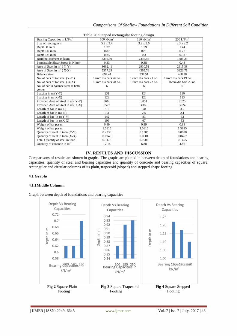
Table 26 Stepped rectangular footing design Bearing Capacities in kN/m2 100 kN/m2 180 kN/m2 250 kN/m2
Size of footing in m 5.2 x 3.4 3.9 x 2.6 3.3 x 2.2
DepthD1 in m 1.77 1.59 1.44
Depth D2 in m 0.87 0.81 0.77
Depth D3 in m 0.25 0.3 0.33
Bending Moment in kNm 3336.99 2336.46 1885.23
Permissible Shear Stress in N/mm2 0.33 0.38 0.43
Area of Steel in m2 ( Y-Y) 3632.41 2910.51 2615.38
Area of Steel in m2 ( X-X) 5577.29 4365.76 3923.71
Balance steel 694.41 537.51 468.38
No. of bars of tor steel (Y-Y ) 12mm dia bars 26 no. 12mm dia bars 21 no. 12mm dia bars 19 no.
No. of bars of tor steel ( X-X) 16mm dia bars 28 no. 16mm dia bars 22 no. 16mm dia bars 20 no.
No. of bar in balance steel at both corner
6 6 6
Spacing in m (Y-Y) 131 124 116
Spacing in m( X-X) 123 120 113
Provided Area of Steel in m2( Y-Y) 3616 3051 2825
Provided Area of Steel in m2( X-X) 5577 4366 3924
Length of bar in m ( L) 5.1 3.8 3.2
Length of bar in m ( B) 3.3 2.5 2.1
Length of bar in m(Y-Y) 142 83 63
Length of bar in m(X-X) 106 67 53
Weight of bar per m 0.89 0.89 0.89
Weight of bar per m 1.5815 1.5815 1.5815
Quantity of steel in tonn (Y-Y) 0.2238 0.1305 0.0988
Quantity of steel in tonn (X-X) 0.0940 0.0601 0.0467
Total Quantity of steel in tonn 0.3178 0.1906 0.1455
Quantity of concrete in m3 12.14 6.88 4.86
IV. RESULTS AND DISCUSSION Comparisons of results are shown in graphs. The graphs are plotted in between depth of foundations and bearing
capacities, quantity of steel and bearing capacities and quantity of concrete and bearing capacities of square,
rectangular and circular columns of its plain, trapezoid (sloped) and stepped shape footing.
4.1 Graphs
4.1.1Middle Column:
Graph between depth of foundations and bearing capacities
Fig 2 Square Plain Fig 3 Square Trapezoid Fig 4 Square Stepped
Footing Footing Footing
0.58
0.6
0.62
0.64
0.66
0.68
0.7
0.72
100 180 250
Dep
th in
m
Bearing Capacities in kN/m2
Depth Vs Bearing Capacities
0.840.850.860.870.880.890.900.910.920.930.94
100 180 250
Dep
th in
m
Bearing Capacities in kN/m2
Depth Vs Bearing Capacities
1.00
1.05
1.10
1.15
1.20
1.25
100 180 250
Dep
th in
m
Bearing Capacities in kN/m2
Depth Vs Bearing Capacities
Comparisons Of Shallow Foundations In Different Soil Condition
| IJMER | ISSN: 2249–6645 www.ijmer.com | Vol. 7 | Iss. 7 | July. 2017 | 49 |
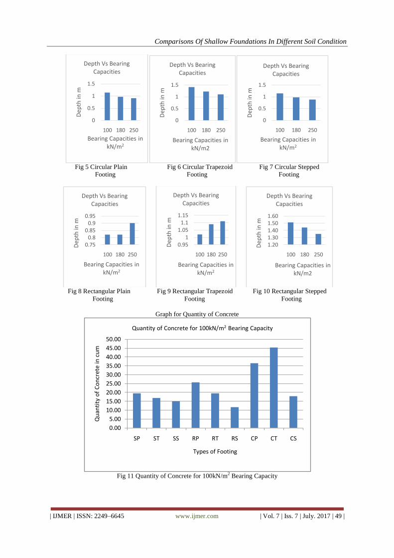
Fig 5 Circular Plain Fig 6 Circular Trapezoid Fig 7 Circular Stepped
Footing Footing Footing
Fig 8 Rectangular Plain Fig 9 Rectangular Trapezoid Fig 10 Rectangular Stepped
Footing Footing Footing
Graph for Quantity of Concrete
Fig 11 Quantity of Concrete for 100kN/m
2 Bearing Capacity
0
0.5
1
1.5
100 180 250
Dep
th in
m
Bearing Capacities in kN/m2
Depth Vs Bearing Capacities
0
0.5
1
1.5
100 180 250
Dep
th in
m
Bearing Capacities in kN/m2
Depth Vs Bearing Capacities
0
0.5
1
1.5
100 180 250
Dep
th in
m
Bearing Capacities in kN/m2
Depth Vs Bearing Capacities
0.750.8
0.850.9
0.95
100 180 250
Dep
th in
m
Bearing Capacities in kN/m2
Depth Vs Bearing Capacities
0.951
1.051.1
1.15
100 180 250
Dep
th in
m
Bearing Capacities in kN/m2
Depth Vs Bearing Capacities
1.201.301.401.501.60
100 180 250D
epth
in m
Bearing Capacities in kN/m2
Depth Vs Bearing Capacities
0.00
5.00
10.00
15.00
20.00
25.00
30.00
35.00
40.00
45.00
50.00
SP ST SS RP RT RS CP CT CS
Qu
anti
ty o
f C
on
cret
e in
cu
m
Types of Footing
Quantity of Concrete for 100kN/m2 Bearing Capacity

Comparisons Of Shallow Foundations In Different Soil Condition
| IJMER | ISSN: 2249–6645 www.ijmer.com | Vol. 7 | Iss. 7 | July. 2017 | 50 |
Fig 12 Quantity of Concrete 180kN/m
2 Bearing Capacity
Fig 13 Quantity of Concrete for 250kN/m
2 Bearing Capacity
Graph for Quantity of Steel
Fig 14 Quantity of Steel for 100kN/m
2 Bearing Capacity
0.00
5.00
10.00
15.00
20.00
25.00
SP ST SS RP RT RS CP CT CS
Qu
anti
ty o
f co
ncr
te in
cu
m
Types of Footing
Quantity of Concrete 180kN/m2 Bearing Capcity
0.00
5.00
10.00
15.00
SP ST SS RP RT RS CP CT CSQu
anti
ty o
f C
on
cret
e in
cu
m
Types of Footing
Quantity of Concrete for 250kN/m2 Bearing Capacity
0.00
0.10
0.20
0.30
0.40
0.50
0.60
0.70
0.80
SP ST SS RP RT RS CP CT CS
Qu
anti
ty o
f St
eel i
n t
on
Types of Footing
Quantity of Steel for 100kN/m2 Bearing Capacity

Comparisons Of Shallow Foundations In Different Soil Condition
| IJMER | ISSN: 2249–6645 www.ijmer.com | Vol. 7 | Iss. 7 | July. 2017 | 51 |
Fig 15 Quantity of Steel for 180kN/m
2 Bearing Capacity
Fig 16 Quantity of Steel for 250kN/m
2 Bearing Capacity
4.1.2Side Column:
Graph between Depth of foundation and bearing capacities
Fig 17 Square Plain Fig 18 Square Trapezoid Fig 19 Square Stepped
Footing Footing Footing
0.00
0.10
0.20
0.30
0.40
0.50
SP ST SS RP RT RS CP CT CS
Qu
anti
ty o
f St
eel i
n t
on
Types of Footing
Quantity of Steel for 180kN/m2 Bearing Capacity
0.00
0.05
0.10
0.15
0.20
0.25
SP ST SS RP RT RS CP CT CS
Qu
anti
ty o
f St
eel i
n t
on
Types of Footing
Quantity of Steel for 250kN/m2 Bearing Capacity
0.00
0.20
0.40
0.60
0.80
1.00
1.20
100 180 250
Dep
th in
m
Bearing Capacities in kN/m2
Depth Vs Bearing Capacities
0.85
0.90
0.95
1.00
1.05
1.10
1.15
100 180 250
Dep
th in
m
Bearing Capacities in kN/m2
Depth Vs Bearing Capacities
1.40
1.50
1.60
1.70
1.80
1.90
100 180 250
Dep
th in
m
Bearing Capacities in kN/m2
Depth Vs Bearing Capacities
Comparisons Of Shallow Foundations In Different Soil Condition
| IJMER | ISSN: 2249–6645 www.ijmer.com | Vol. 7 | Iss. 7 | July. 2017 | 52 |
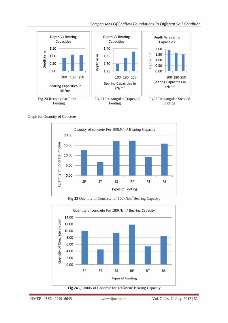
Fig 20 Rectangular Plain Fig 21 Rectangular Trapezoid Fig22 Rectangular Stepped
Footing Footing Footing
Graph for Quantity of Concrete
Fig 23 Quantity of Concrete for 100kN/m
2Bearing Capacity
Fig 24 Quantity of Concrete for 180kN/m
2 Bearing Capacity
0.00
0.50
1.00
1.50
100 180 250
Dep
th in
m
Bearing Capacities in kN/m2
Depth Vs Bearing Capacities
1.25
1.30
1.35
1.40
100 180 250
Dep
th in
m
Bearing Capacities in kN/m2
Depth Vs Bearing Capacities
0.00
0.50
1.00
1.50
2.00
100 180 250
Dep
th in
m
Bearing Capacities in kN/m2
Depth Vs Bearing Capacities
0.00
5.00
10.00
15.00
20.00
SP ST SS RP RT RS
Qu
anti
ty o
f C
on
cret
e im
cu
m
Types of Footing
Quantity of concrete For 100kN/m2 Bearing Capacity
0.00
2.00
4.00
6.00
8.00
10.00
12.00
14.00
SP ST SS RP RT RS
Qu
anti
ty o
f C
on
cret
e im
cu
m
Types of Footing
Quantity of concrete For 180kN/m2 Bearing Capacity

Comparisons Of Shallow Foundations In Different Soil Condition
| IJMER | ISSN: 2249–6645 www.ijmer.com | Vol. 7 | Iss. 7 | July. 2017 | 53 |
Fig 25 Quantity of concrete for 250kN/m
2 Bearing Capacity
Graph for Quantity of Steel
Fig 26 Quantity of Steel for 100kN/m
2 Bearing Capacity
Fig 27Quantity of Steel for180 kN/m
2 Bearing Capacity
0.00
1.00
2.00
3.00
4.00
5.00
6.00
7.00
8.00
9.00
SP ST SS RP RT RS
Qu
anti
ty o
f C
on
cret
e im
cu
m
Types of Footing
Quantity of concrete for 250kN/m2 Bearing Capacity
0.0000
0.2000
0.4000
0.6000
0.8000
1.0000
1.2000
SP ST SS RP RT RS
Qu
anti
ty o
f St
ee
l in
to
n
Types of Footing
QTY OF STEEL FOR 100kn/m2Bearing Capacity
0.0000
0.0500
0.1000
0.1500
0.2000
0.2500
0.3000
0.3500
0.4000
SP ST SS RP RT RS
Qu
anti
ty o
f St
eel i
n t
on
Types of Footing
Quantity of Steel for 180 kN/m2 Bearing Capacity

Comparisons Of Shallow Foundations In Different Soil Condition
| IJMER | ISSN: 2249–6645 www.ijmer.com | Vol. 7 | Iss. 7 | July. 2017 | 54 |
Fig 28 Quantity of Steel for 250kN/m
2 Bearing Capacity
4.1.3Corner Column:
Graph between Depth of foundation and bearing capacities
Fig 29 Square Plain Fig 30 Square Trapezoid Fig 31 Square Stepped
Footing Footing Footing
Fig 32 Rectangular Plain Fig 33 Rectangular Trapezoid Fig 34 Square Stepped
Footing Footing Footing
0.0000
0.0500
0.1000
0.1500
0.2000
0.2500
SP ST SS RP RT RS
Qu
anti
ty o
f St
eel i
n t
on
Types of Footing
Quantity of Steel for 250 kN/m2 Bearing Capacity
0.80
0.85
0.90
0.95
1.00
1.05
100 180 250
Dep
th in
m
Bearing Capacities in kN/m2
Depth Vs Bearing Capacities
1.251.261.261.271.271.281.281.29
100 180 250
Dep
th in
m
Bearing Capacities in kN/m2
Depth Vs Bearing Capacities
1.30
1.40
1.50
1.60
1.70
1.80
1.90
100 180 250
Dep
th in
m
Bearing Capacities in kN/m2
Depth Vs Bearing Capacities
0.82
0.84
0.86
0.88
0.90
100 180 250
Dep
th in
m
Bearing Capacities in kN/m2
Depth Vs Bearing Capacities
1.15
1.20
1.25
1.30
1.35
100 180 250
Dep
th in
m
Bearing Capacities in kN/m2
Depth Vs Bearing Capacities
0.00
0.50
1.00
1.50
2.00
100 180 250
Dep
th in
m
Bearing Capacities in kN/m2
Depth Vs Bearing Capacities
Comparisons Of Shallow Foundations In Different Soil Condition
| IJMER | ISSN: 2249–6645 www.ijmer.com | Vol. 7 | Iss. 7 | July. 2017 | 55 |
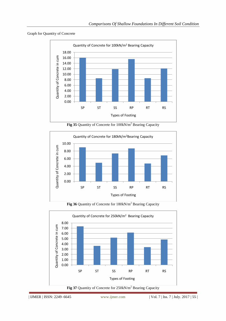
Graph for Quantity of Concrete
Fig 35 Quantity of Concrete for 100kN/m
2 Bearing Capacity
Fig 36 Quantity of Concrete for 180kN/m
2 Bearing Capacity
Fig 37 Quantity of Concrete for 250kN/m
2 Bearing Capacity
0.00
2.00
4.00
6.00
8.00
10.00
12.00
14.00
16.00
18.00
SP ST SS RP RT RS
Qu
anti
ty o
f C
on
cret
e in
cu
m
Types of Footing
Quantity of Concrete for 100kN/m2 Bearing Capacity
0.00
2.00
4.00
6.00
8.00
10.00
SP ST SS RP RT RSQu
anti
ty o
f C
on
cret
e in
cu
m
Types of Footing
Quantity of Concrete for 180kN/m2Bearing Capacity
0.00
1.00
2.00
3.00
4.00
5.00
6.00
7.00
8.00
SP ST SS RP RT RS
Qu
anti
ty o
f C
on
cret
e in
cu
m
Types of Footing
Quantity of Concrete for 250kN/m2 Bearing Capacity

Comparisons Of Shallow Foundations In Different Soil Condition
| IJMER | ISSN: 2249–6645 www.ijmer.com | Vol. 7 | Iss. 7 | July. 2017 | 56 |
Graph for Quantity of Steel
Fig 38 Quantity of Steel for 100kN/m
2 Bearing Capacity
Fig 39 Quantity of Steel for 180kN/m
2 Bearing Capacity
Fig 40 Quantity of Steel for 250kN/m
2 Bearing Capacity
0.0000
0.1000
0.2000
0.3000
0.4000
0.5000
0.6000
0.7000
0.8000
SP ST SS RP RT RS
Qu
anti
ty o
f St
eel i
n t
on
Types of Footing
Quantity of Steel for 100 kN/m2 Bearing Capacity
0.0000
0.1000
0.2000
0.3000
0.4000
SP ST SS RP RT RS
Qu
anti
ty o
f St
eel i
n t
on
Types of Footing
Quantity of Steel for 180 kN/m2 Bearing Capacity
0.0000
0.0500
0.1000
0.1500
0.2000
0.2500
0.3000
SP ST SS RP RT RS
Qu
anti
ty o
f St
eel i
n t
on
Types of Footing
Quantity of Steel for 250 kN/m2 Bearing Capacity

Comparisons Of Shallow Foundations In Different Soil Condition
| IJMER | ISSN: 2249–6645 www.ijmer.com | Vol. 7 | Iss. 7 | July. 2017 | 57 |
4.2 Cost of Footing
Rate of steel is 44000 Rs. Per tonn is taken from Steel Authority of India Limited (SAIL) and rate of
M-20 concrete is 4500 Rs. per cubic meter is taken from as per rate analysis of current market rate.
Cost of quantity of steel required for middle column as tabulated below
Table 27 Cost of Quantity of Steel in Lac Types of footing 100 kN/m2 180 kN/m2 250 kN/m2
Square plain footing 0.31 0.17 0.10
Square trapezoid footing 0.19 0.09 0.06
Square stepped footing 0.15 0.09 0.07
Circular plain footing 0.12 0.08 0.06
Circular trapezoid footing 0.11 0.07 0.05
Circular stepped footing 0.13 0.08 0.06
Rectangular plain footing 0.23 0.12 0.08
Rectangular trapezoid footing 0.21 0.10 0.07
Rectangular stepped footing 0.12 0.06 0.05
Cost of quantity of concrete required for middle column as tabulated below
Table 28 Cost of Quantity of Concrete in Lac Types of footing 100 kN/m2 180 kN/m2 250 kN/m2
Square plain footing 0.87 0.48 0.41
Square trapezoid footing 0.62 0.36 0.27
Square stepped footing 0.67 0.38 0.25
Circular plain footing 1.64 0.78 0.51
Circular trapezoid footing 2.04 0.99 0.62
Circular stepped footing 0.80 0.41 0.30
Rectangular plain footing 1.15 0.63 0.51
Rectangular trapezoid footing 0.69 0.40 0.30
Rectangular stepped footing 0.74 0.44 0.32
Cost of quantity of steel required for side column as tabulated below
Table 29 Cost of Quantity of Steel in Lac Types of footing 100 kN/m2 180 kN/m2 250 kN/m2
Square plain footing 0.46 0.15 0.09
Square trapezoid footing 0.19 0.09 0.06
Square stepped footing 0.14 0.07 0.05
Rectangular plain footing 0.16 0.07 0.05
Rectangular trapezoid footing 0.10 0.05 0.04
Rectangular stepped footing 0.09 0.05 0.04
Cost of quantity of concrete required for side column as tabulated below
Table 30 Cost of Quantity of Concrete in Lac Types of footing 100 kN/m2 180 kN/m2 250 kN/m2
Square plain footing 0.56 0.45 0.37
Square trapezoid footing 0.30 0.20 0.14
Square stepped footing 0.76 0.42 0.29
Rectangular plain footing 0.77 0.53 0.38
Rectangular trapezoid
footing
0.41 0.24 0.18
Rectangular stepped footing 0.71 0.37 0.25
Cost of quantity of steel required for corner column as tabulated below
Table 31 Cost of Quantity of Steel in Lac Types of footing 100 kN/m2 180 kN/m2 250 kN/m2
Square plain footing 0.28 0.14 0.08
Square trapezoid footing 0.15 0.07 0.05
Square stepped footing 0.13 0.07 0.05
Rectangular plain footing 0.29 0.16 0.11
Rectangular trapezoid footing 0.15 0.09 0.06
Rectangular stepped footing 0.13 0.08 0.06
Comparisons Of Shallow Foundations In Different Soil Condition
| IJMER | ISSN: 2249–6645 www.ijmer.com | Vol. 7 | Iss. 7 | July. 2017 | 58 |
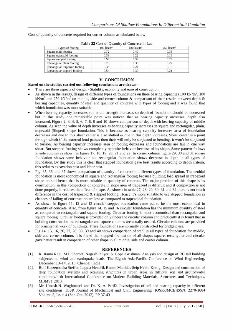
Cost of quantity of concrete required for corner column as tabulated below
Table 32 Cost of Quantity of Concrete in Lac Types of footing 100 kN/m2 180 kN/m2 250 kN/m2
Square plain footing 0.72 0.40 0.33
Square trapezoid footing 0.38 0.22 0.16
Square stepped footing 0.53 0.33 0.23
Rectangular plain footing 0.70 0.39 0.27
Rectangular trapezoid footing 0.38 0.21 0.15
Rectangular stepped footing 0.54 0.30 0.21
V. CONCLUSION Based on the studies carried out following conclusions are drawn -
There are three aspects of design - Stability, economy and ease of construction.
As shown in the results, design of different types of foundations on three bearing capacities 100 kN/m2, 180
kN/m2 and 250 kN/m
2 on middle, side and corner column & comparison of their results between depth &
bearing capacities, quantity of steel and quantity of concrete with types of footing and it was found that
which foundation was most suitable.
When bearing capacity increases soil strata strength increases so depth of foundation should be decreased
but in this study one remarkable point was noticed that as bearing capacity increases, depth also
increased. Figure 2, 3, 4, 5, 6, 7, 8, 9 and 10 shows comparison of depth with bearing capacity of middle
column. As seen the value of depth increases as bearing capacity increases in square and rectangular, plain,
trapezoid (Sloped) shape foundation. This is because as bearing capacity increases area of foundation
decreases and due to this shear center is also shifted & due to this depth increases. Shear center is a point
through which if the external load passes then their will only be subjected to bending, it won’t be subjected
to torsion. As bearing capacity increases area of footing decreases and foundations are fail in one way
shear. But stepped footing shows completely opposite behavior because of its shape. Same pattern follows
in side column as shown in figure 17, 18, 19, 20, 21 and 22. In corner column figure 29, 30 and 31 square
foundation shows same behavior but rectangular foundation shows decrease in depth in all types of
foundation. By this study this is clear that stepped foundation gave best results according to depth criteria,
this reduces excavation cost and labor cost.
Fig. 35, 36, and 37 shows comparison of quantity of concrete in different types of foundation. Trapezoidal
foundation is most economical in square and rectangular footing because building load spread in trapezoid
shape on soil hence that is more suitable in quantity of concrete. The major problem of this shape is its
construction, in this compaction of concrete in slope area of trapezoid is difficult and if compaction is not
done properly, it reduces the effect of shape. As shown in table 27, 28, 29, 30, 31 and 32 there is not much
difference in the cost of trapezoid & stepped footing. Hence it’s more suitable to use stepped foundation as
chances of failing of construction are less as compared to trapezoidal foundation.
As shown in figure 11, 12 and 13 circular stepped foundation came out to be the most economical in
quantity of concrete. Also, from figure 14, 15 and 16 circular foundation has the minimum quantity of steel
as compared to rectangular and square footing. Circular footing is most economical than rectangular and
square footing. Circular footing is provided only under the circular column and practically it is found that in
building construction the rectangular and square columns are usually needed. Circular columns are provided
for ornamental work of buildings. These foundations are normally constructed for bridge piers.
Fig 14, 15, 16, 26, 27, 28, 38, 39 and 40 shows comparison of steel in all types of foundation for middle,
side and corner column. It is found that stepped foundation of all shapes square, rectangular and circular
gave better result in comparison of other shape in all middle, side and corner column.
REFERENCES [1]. K. Rama Raju, M.I. Shereef, Nagesh R Iyer, S. Gopalakrishnan. Analysis and design of RC tall building
subjected to wind and earthquake loads. The Eighth Asia-Pacific Conference on Wind Engineering,
December 10–14, 2013, Chennai, India
[2]. Rolf Katzenbacha Steffen Leppla Hendrik Ramm Matthias Seip Heiko Kuttig. Design and construction of
deep foundation systems and retaining structures in urban areas in difficult soil and groundwater
conditions.11th International Conference on Modern Building Materials, Structures and Techniques,
MBMST 2013.
[3]. Mr. Umesh N. Waghmare1 and Dr. K. A. Patil2. Investigation of soil and bearing capacity in different
site conditions. IOSR Journal of Mechanical and Civil Engineering (IOSR-JMCE)ISSN: 2278-1684
Volume 3, Issue 4 (Sep-Oct. 2012), PP 37-43

Comparisons Of Shallow Foundations In Different Soil Condition
| IJMER | ISSN: 2249–6645 www.ijmer.com | Vol. 7 | Iss. 7 | July. 2017 | 59 |
[4]. Harry G. Poulos, Dist. MASCE. Foundation Design for Tall Buildings. Geotechnical Special Publication
· May 2012
[5]. Adel Belal. Numerical Evaluation of Bearing Capacity of Square Footing on Geosynthetic Reinforced
Sand. Proceedings of the International Conference on Civil, Structural and Transportation Engineering
Ottawa, Ontario, Canada, May 4 – 5, 2015 Paper No. 143
[6]. C. K. LAU and M. D. BOLTON. The bearing capacity of footings on granular soils II: Experimental
evidence. Lau, C. K. & Bolton, M. D. (2011). Geotechnique 61, No. 8, 639–650.
[7]. Y. Tian & M.J. Cassidy, M. Uzielli. Probabilistic Assessment of the Bearing Capacity of Shallow Strip
Footings on Stiff-Over-Soft Clay. Proceedings of the 18th International Conference on Soil Mechanics
and Geotechnical Engineering, Paris 2013
[8]. M.S. Dixit, K.A. Patil. Study of effect of different parameters on bearing capacity of soil. IGC 2009,
Guntur, INDIA
[9]. Andrzej Sawicki, Waldemar swidzinski Bodhan Zadroga. Settlement of Shallow foundation due to cyclic
vertical force. Soils and Foundations Vol.38, No. 1, 35-43, March 1998.Japanese Geotechnical Society.
[10]. D.V. Griffiths, MASCE, Gordon A. Fenton, M.ASCE, and N. Manoharan, AffASCE. Bearing capacity of
Rough Rigid Strip Footing on Cohesive Soil: Probabilistic Study. Journal of Geotechnical and Geo
environmental Engineering, September 2002.
[11]. Bijay Sarkar, Analysis of isolated footing subjected to axial load and high biaxial moments and numerical
approach for its solution. The Indian Concrete Journal June 2014.
[12]. Arnulfo Lu evanos Rojas, Jesus Gerardo Faudoa Herrera Roberto Alan Andrade Vallejo and Miguel
Armando Cano Alvarez, Design of isolated footings of rectangular form using a new model. International
Journal of Innovative Computing, Information and Control Volume 9, Number 10, October 2013.
*Jain Shrutika " Comparisons of Shallow Foundations in Different Soil Condition." International Journal
Of Modern Engineering Research (IJMER) 7.7 (2017): 37-59.