compatibility studies of potential in molten fluoride...
TRANSCRIPT
Compatibility Studies of Potential MoltenSalt Breeder Reactor Materials 44
in Molten Fluoride Salts -1 J. R. Keiser
BISTRIBUT~ON OF THIS DOCUMENT IS UNLIMITEI
OAK RIDGE NATIONAL LABORATORY OPERATED BY UNION CARBIDE CORPORATION FOR THE ENERGY - :H AND DEYELOPMLNT ADMINISTRATION
DISCLAIMER
This report was prepared as an account of work sponsored by an agency of the United States Government. Neither the United States Government nor any agency Thereof, nor any of their employees, makes any warranty, express or implied, or assumes any legal liability or responsibility for the accuracy, completeness, or usefulness of any information, apparatus, product, or process disclosed, or represents that its use would not infringe privately owned rights. Reference herein to any specific commercial product, process, or service by trade name, trademark, manufacturer, or otherwise does not necessarily constitute or imply its endorsement, recommendation, or favoring by the United States Government or any agency thereof. The views and opinions of authors expressed herein do not necessarily state or reflect those of the United States Government or any agency thereof.
DISCLAIMER
Portions of this document may be illegible in electronic image products. Images are produced from the best available original document.

7 .
Printed in the United States of America. Available from National Technical Information Service
U.S. Department of Commerce 5285 Port Royal Road, Springfield, Virginia 22161
Price Printed Copy $4.00; Microfiche $3.00
This report was prepared as an account of work sponsored by the United States Government. Neither the United States nor the Energy Research and Development Administration/United States Nuclear Regulatory Commission, nor any of their employees, nor any of their contractors, subcontractors, or their employees, makes any warranty, express or implied, or assumes any legal liability or responsibility forthe accuracy, completeness or usefulness of any information, apparatus, product or process disclosed, or represents that its use would not infringe privatelyowned rights.
. ORNL/TM-5783 ~istribbtion category UC-76
Contract No. W-7405-eng-26 . .
METALS AND CERAMICS DIVISION
COMPATIBILITY STUDIES OF POTENTIAL MOLTEN-SALT. BREEDER REACTOR MATERIALS IN MOLTEN FLUORIDE SALTS
.J. R.' Keiser
Date Published: May 1977 - - .
spomred by the United S a t e G m e n t . Neither tht ~ " i ! t d SIUIW n ~ r the ullited Eetos
-- 1
NOTICE This document contains information of a preliminary nature. I t is subject to revision or correction and therefore does not represent a final report.
. OAK RIDGE NATIONAL .LABORATORY Oak Ridge, Tennessee ,37830
operated by UNION CARBIDE CORPORATION ''
for the
DISTRIBUTION OF THIS DOCUMENT IS UNLlMlTED ,m

I
THIS PAGE
WAS INTENTIONALLY
LEFT BLANK
CONTENTS
Page
ABSTRACT . . . . . . . . . . . . . . . . . . . . . . . . . . . . . . . . INTRODUCTION . . . . . . . . . . . . . . . . . . . . . . . . . . . EXPERIMENTAL METHODS . . . . . . . . . . . . . . . . . . . . . . . EXPERIMENTAL RESULTS . . . . . . . . . . . . . . . . . . . . . . .
. . . . . . . . . . . . . . . . . Thermal-Convection Loop 21A
. . . . . . . . . . . . . . . . . Thermal-Convection Loop 23
. . . . . . . . . . . . . . . . . Thermal-Convection Loop 31
. . . . . . . . . . . . . Thermal-Convection Loops 18C and 24
. . . . . . . . . . . . . . . Forced-Circulation Loop FCL-2B
. . . . . . . . . . . . . . . . . . . . . . . . . . . CONCLUSIONS
. . . . . . . . . . . . . . . . . . . . . . . . . . ACKNOWLEDGMENTS
iii
COMPATIBILITY STUDIES OF POTENTIAL MOLTEN-SALT BREEDER REACTOR MATERIALS I N MOLTEN FLUORIDE SALTS
J. R. Keiser
ABSTRACT
Th i s r e p o r t summarizes t h e molten f l u o r i d e s a l t c o m p a t i b i l i t y s t u d i e s c a r r i e d ou t dur ing t h e period 1974-76 i n support of t h e Molten-Salt Reactor Program. Thermal-convection and forced- c i r c u l a t i o n loops were used t o measure t h e c o r r o s i o n . r a t e of s e l e c t e d a l l o y s . Resu l t s confirmed t h e r e l a t i o n s h i p of t ime, i n i t i a l chromium concent ra t ion , and mass l o s s developed by previous workers. The co r ros ion r a t e s of Has te l loy N and Has te l loy N modified by t h e a d d i t i o n of 1-3 w t % Nb were w e l l w i t h i n t h e accep tab le range f o r u se i n a n MSBR.
INTRODUCTION
The purpose of t h i s r e p o r t is t o summarize t h e co r ros ion s t u d i e s
c a r r i e d . o u t f o r t he Molten-Salt Reactor Program dur ing t h e per iod
September 1974 through May 1976. These s t u d i e s were intended t o determine
t h e co r ros ion r e s i s t a n c e of p o t e n t i a l Molten-Salt Breeder Reactor contain-
ment v e s s e l m a t e r i a l s i n molten f luor ide . s a l t . The nickel-base a l l o y
Has te l loy N was used s u c c e s s f u l l y f o r t h e containment v e s s e l of a n
experimental molten-sal t r e a c t o r , t h e Molten-Salt 'Reactor Experiment.
However, t h e d iscovery of i r r a d i a t i o n embri t t lement and g r a i n boundary
embri t t lement by the f i s s i p n product t e l l u r i u m l ed t o a program to
develop a n a l l o y t h a t would be s u f f i c i e n t l y r e s i s t a n t t o t h e cond i t i ons .
To ensure . t ha t any new o r modified a l l o y would have a h igh r e s i s t a n c e
t o corrosion by t h e f l u o r i d e s a l t , s a l t -me ta l co r ros ion s t u d i e s were
made. Ma te r i a l s i nves t iga t ed inc lude Has t e l loy N , chromium and niobium
modif ica t ions of Has te l loy N , Inconel 601, and type 316 s t a i n l e s s s t e e l .
The s t a i n l e s s s t e e l was t e s t e d i n L ~ F - B ~ F ~ (65-35 mole %), and t h e o t h e r
a l l o y s were t e s t e d i n MSBR f u e l s a l t , LiF-BeF2-ThF4-UFk
(72-16-11.7-0.3 mole %).
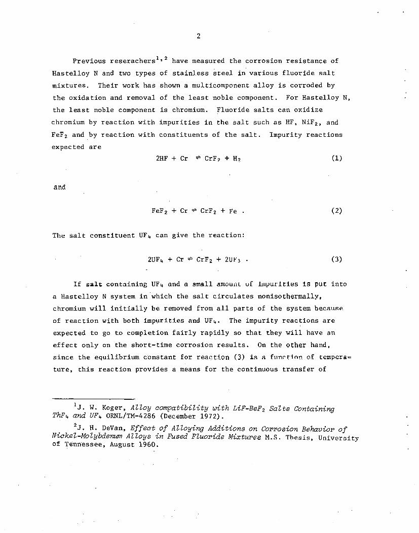
Prev ious r e s e r a c h e r s l have measured t h e c o r r o s i o n r e s i s t a n c e of
H a s t e l l o y N and two types of s t a i n l e s s s t e e l i n v a r i o u s f l u o r i d e s a l t
m ix tu re s . The i r work h a s shown a multicomponent a l l o y i s corroded by
t h e o x i d a t i o n and removal of t h e l e a s t noble component. For Has t e l l oy N ,
t h e l e a s t noble component i s chromium. F l u o r i d e salts can o x i d i z e
chromium by r e a c t i o n w i t h i m p u r i t i e s i n t h e s a l t such a s HF, NiF2, and
FeF2 and by r e a c t i o n w i t h c o n s t i t u e n t s of t h e s a l t . Impur i ty r e a c t i o n s
expected a r e
2HF + C r * CrF7 + H?
FeF2 + C r * CrF2 + Fe .
The s a l t c o n s t i t u e n t UF4 can g ive t h e r e a c t i o n :
I f s a l t con ta in ing UFI+ and a small anloulrt. ul: Lopurl t i e s I s put i n t o
a H a s t e l l o y N system in 'wh ich t h e s a l t c i r c u l a t e s noniso thermal ly ,
chromium w i l l i n i t i a l l y be removed from a l l p a r t s of t h e system because.
of r e a c t i o n w i t h bo th i m p u r i t i e s and UF4. The impur i ty r e a c t i o n s a r e
expected t o go t o complet ion f a i r l y r a p i d l y so t h a t they w i l l have a n
e f f e c t o n l y on t h e shor t - t ime c o r r o s i o n r e s u l t s . On the o ther hand,
s i n c e t h e equi l ibr . ium c o n s t a n t f o r r eac t zon ( 3 ) is a f i i n r t i n n of tempera=
t u r e , c h i s r e a c t i o n provides a means f o r t h e cont inuous t r a n s f e r of
' J. W. Koger , Alloy compatibility with LiF-BeF2 Salts Containing ThF4 and UF4 ORNL/TM-4286 (December 1972).
2 ~ . H. DeVan, Effect of Alloying Additions on Corrosion ~ehavior of Nickel-Molybdenwn Alloys in Fused Fluoride Mixtures M.S. Thesis, Univers i ty of Tenn'essee, August 1960.
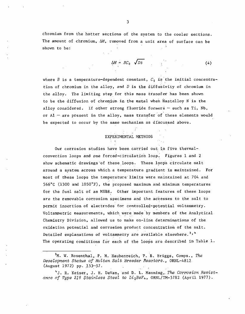
chromium from t h e h o t t e r s e c t i o n s of t h e system t o t h e coo le r s e c t i o n s .
The amount of chromium, AM, removed from a u n i t a r e a of s u r f a c e can be
shown t o be:
where B i s a temperature-dependent cons t an t , Co i s t h e i n i t i a l concentra-
t i o n of chromium i n t h e a l l o y , and D is t h e d i f f u s i v i t y of chromium i n
t h e a l l o y . The l i m i t i n g s t e p f o r t h i s mass t r a n s f e r has been shown
t o be t h e d i f f u s i o n of chrom.iGm i n t h e meta l when k a s t e l l o y N i s t h e
a l l o y considered. I f o the r s t r o n g f l u o r i d e furmers - such a s T i , Nb,
o r A l - a r e p re sen t i n t h e a l l o y , mass t r a n s f e r of t h e s e elements would
be expected t o occur by t h e same mechanism a s d iscussed above. I ' . . .
EXPERIMENTAL METHODS ' . . ',..
Our co r ros ion s t u d i e s have been c a r r i e d out: i n f i v e thermal-
convect ion loops and one fo rced -c i r cu la t ion loop. F igures 1 and 2 . .
show schematic drawings -of t h e s e , loops . These loops c i r c u l a t e . s a l t
around a system a c r o s s which .a temperature g r a d i e n t i s maintained. For
most of t h e s e loops t h e t e m p e r a t u r e ' l i m i t s were maintained a t 704 and
566°C (1300 and 1050°.F), t h e proposed maximum and minimum temperatures
f o r t h e f u e l s a l t of a n MSBR. Other important f e a t u r e s of t hese loops
a r e t h e removable co r ros ion specimens and t h e ac-cesses t o t h e s a l t t o
permit i n a e r t i o n of e l e c t r o d e s f o r con. t rol led.-potent ial voltammetry.
Voltammetric measurements, which. were 'made 'by members of t h e Ana ly t i ca l , . .
Chemistry Divis ion, allowed u s t o make on-l ine de te rmina t ions of t h e
ox ida t ion p o t e n t i a l and co r ros ion product concen t r a t ion of t he s a l t .
Deta i led explana t ions of v o l tammetry a r e a v a i l a b l e elsewhere.
The ope ra t ing cond i t i ons f i r each of t h e loo$s a r e descr ibed i n Table 1.
3 ~ . W. Rosenthal , . P . N. Haubenreich, .P. .B. Briggs, Comps., The DeveZopment Status of Molten Sal t Breeder Reactors., ORNL-4812 (August 1972) pp. ,153-57.
... . 'J. R. Ke i se r , J. H. DeVan, and D. L. Manni-ng,: The Corrosion Resist-
ance of Tupe 326 Stainless Steel to Li2BeFb, ORNL/TM-5782 (Apr i l 1977).
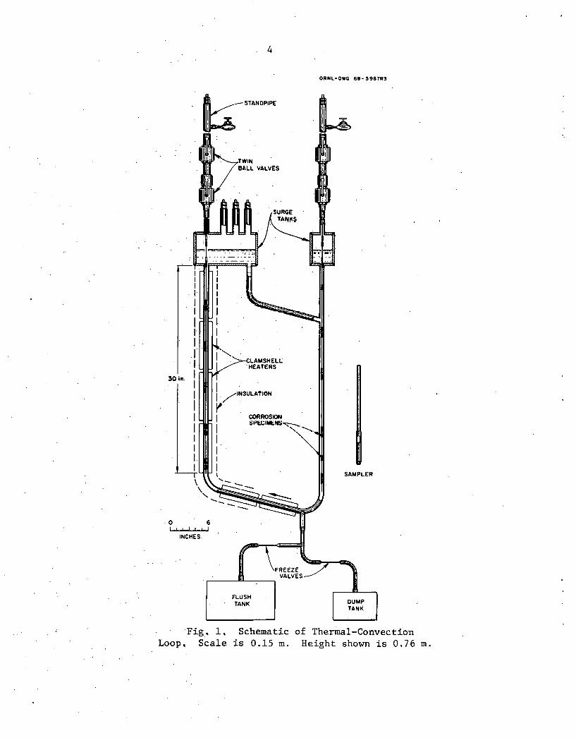
ORNL-DWG 6 8 - 3 9 8 7 R 3
30 in.
. O 6 - INCHES
u . . .Fig, 1, Schematic of ~hermal-Convection Loop, Scale is 0.15 m. Height shown is 0.76 m.
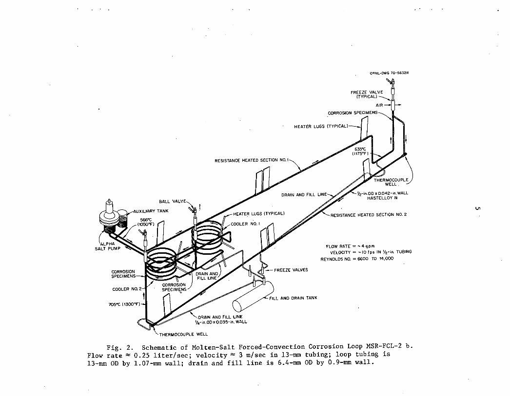
ORNL-OWG 7 0 - 5 6 3 2 R
CORROSION SPECIMENS
HEATER LUGS (TYPICAL)
RESISTANCE HEATED SECTION NO. I
DRAIN AND FILL LIN %-inOD x 0.042-in.WALL HASTELLOY N
FLOW RPTE'= - 4 qpm
VELOCITY = -10 Fps IN %-in. TUBING
REYNOLDS NO. = 6 6 0 0 TO 14,000
FREEZE VALVES
L AND DRAIN TANK
"THERMOCOUPLE WELL
Fig . 2. Schematic of Molten-Salt Forced-Convection Corrosion Loop MSR-FCL-2 b. Flow r a t e C 0.25 l i t e r l s e c ; v e l o c i t y " 3 mlsec i n 13-mm tubing; loop tubing is 13-mm OD by. 1.07-mrn wzl l ; d r a i n and f i l l l i n e i s 6.4-mm OD by 0.9-mm wa l l .
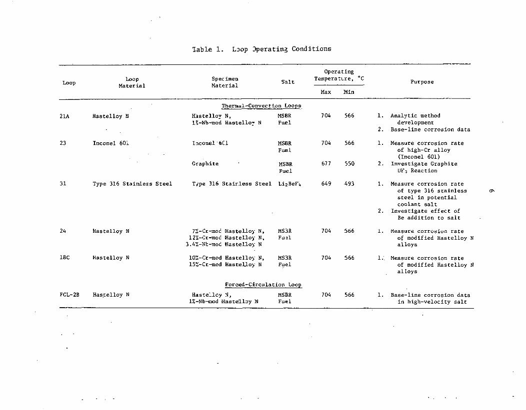
Zab1.e 1. L3o.p 3peratinz Conditions
Opera t ing
Loop h o p M a t e r i a l
Spec h e n S a l t Temperatcre, O C
Ma te r i a l Purpose
Max Min
P h e m l - C o m e c t i o n Loops,
2 1 A Has t e l l oy N b s t e l l o y 'N , MSBR 704 566 1. Ana ly t i c method 1%-Nb-mod ha st el lo^ N Fue l development
2. Base-l ine c o r r o s i o n d a t a
23 Incone l 601 I ~ c o n e l 6C1 MSBR 704 566 1. Fue 1
Graph i t e MSBR 677 550 2 . Fuel
3 1 Type 316 S t a i n l e s s S t e e l Tdpe 316 S t a i r . l e s s S t e e l Li2BeF1 649 ,493 1.
24 Has t e l l o y N
18C H a s t e l . 1 0 ~ N
Forced-CirculatLon Loop
Has t e l l c~y N, MSBR 704 566 1. 1%-Nb-d H a s t e l l ~ y N Fuel
Measure c o r r o s i o n r a t e of high-Cr a l l o y (Lnconel 601)
I n v e s t i g a t e Graph i t e U F 3 React ion
Measure c o r r o s i o n r a t e of type 316 s t a i n l e s s s t e e l i n p o t e n t i a l c o o l a n t s a l t
I n v e s t i g a t e e f f e c t of Be a d d i t i o n t o s a l t
Measure c o r r o s i u n r a t e of modified Has t e l l oy N a l l o y s
Measure c o r r o s i o n r a t e of modified Has t e l l oy N a l l o y s
Base-l ine c o r r o s i o n d a t a i n h igh-veloc i ty s a l t
EXPERIMENTAL RESULTS
Thermal-Convection Loop 21A
Has te l loy N loop NCL 21A was t h e f i r s t loop t o be p u t i n t o ope ra t ion
when t h e Molten-Salt Reactor Program was resumed i n 1974. A s such, t h e
loop was used t o o b t a i n base- l ine co r ros ion d a t a f o r Has t e l loy N and t o
provide a t e s t bed f o r voltammetry measurements of MSBR f u e l s a l t . The
voltammetry r e s u l t s showed t h a t t h e ox ida t ion p o t e n t i a l a s r e f l e c t e d
by t h e U(IV)/U(III) r a t i o remained q u i t e h igh throughout t h e 17.5 months
of ope ra t ion . I n fact, w i t h a U(IV)/U(III) r a t i o of about l o 4 loop 21A
contained t h e most ox id i z ing s a l t of a l l t h e loop experiments.
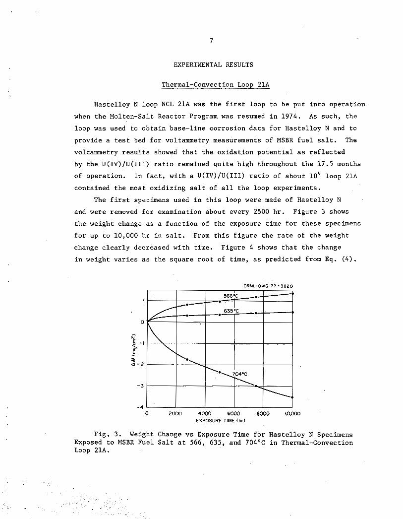
The f i r s t specimens used i n t h i s loop were made of Has te l loy N
and were removed f o r examination about every 2500 h r . F igure 3 shows
t h e weight change a s a f u n c t i o n of t h e exposure t ime f o r t h e s e specimens
f o r up t o 10,000 hr i n s a l t . From t h i s f i g u r e t h e r a t e of t h e weight
change c l e a r l y decreased w i t h t ime. F igure 4 shows t h a t t h e change
i n weight v a r i e s as t h e square r o o t of time, a s p red ic t ed from Eq. (4) .
ORNL-DWG 77 -3820
0 2000 4000 6000 $099 !o,ooo EXPOSURE TIME (hr)
Fig . 3. Weight Change v s Exposure Time f o r Has te l loy N Specimens Exposed t o MSBR Fuel S a l t a t 566, 635, and 704°C i n Thermal-Convection Loop 21A.
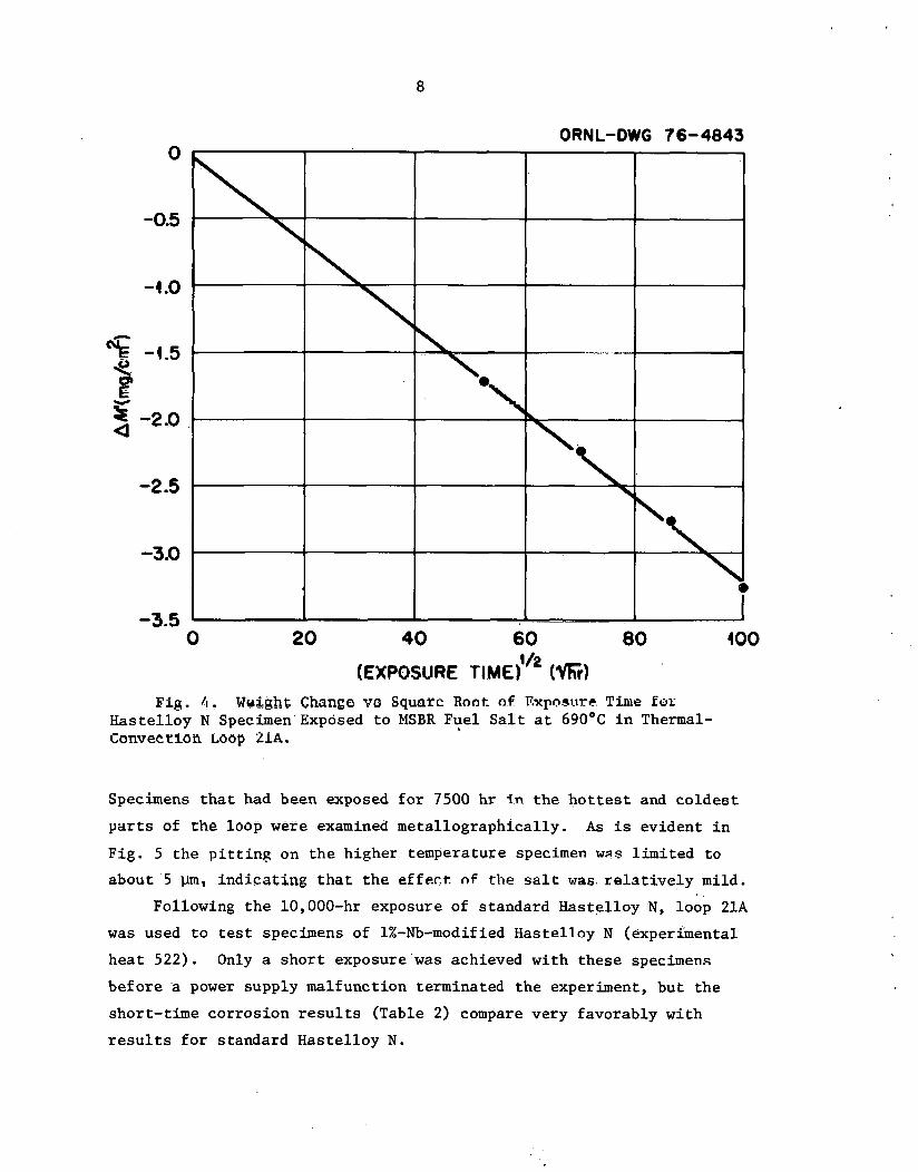
8
ORNL-DWG 76-4843
Big . 4 . Wu$&hf Change ve Squnrc Root a f Exposure Time Eor Haste l loy N Specimen'Exposed t o MSBR Fuel , S a l t a t 690°C i n Thermal- Convection Loop 21~.
Specimens t h a t had been exposed f o r 7500 hr i n t h e h o t t e s t and c o l d e s t
p a r t s of the loop were examined meta l lographica l ly . A s is evident i n
Fig . 5 the p i t t i n g on t h e higher temperature specimen was l imi ted t o
about 5 urn, i nd ica t ing that the effect. nf the s a l t w a s r e l a t i v e l y mild.
Following t h e 10,000-hr exposure of s tandard Hastel loy N, loop 21A
was used t o t e s t specimens of 1%-Nb-modified Hastel loy N (experimental
h e a t 522). Only a s h o r t exposure was achieved wi th these specimens
be fo re a power supply malfunction terminated the experiment, but t h e
short- t ime corros ion r e s u l t s (Table 2) compare very favorably with
r e s u l t s f o r s tandard Haste l loy N .
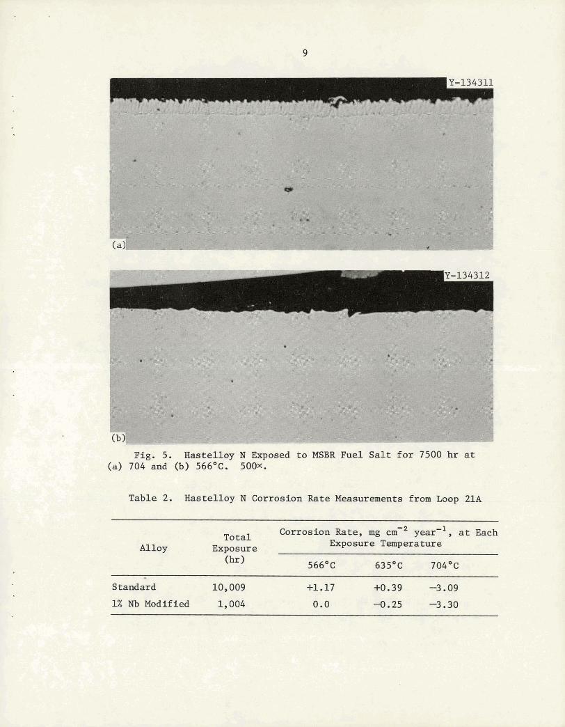
Fig. 5. Hastelloy N Exposed to MSBR Fuel Salt for 7500 hr a t (a) 704 and (b) 566OC. 500x.
Table 2. Hastelloy N Corrosion Rate Measurements from Loop 21A
Alloy Total Corrosion Rate, mg ~ r n - ~ year'1, at Each
Exposure Exposure Temperature A- -
- Standard 10,009 +1.17 H.39 -3.09
1% Nb Modified 1,004 0.0 -0.25 -3.30
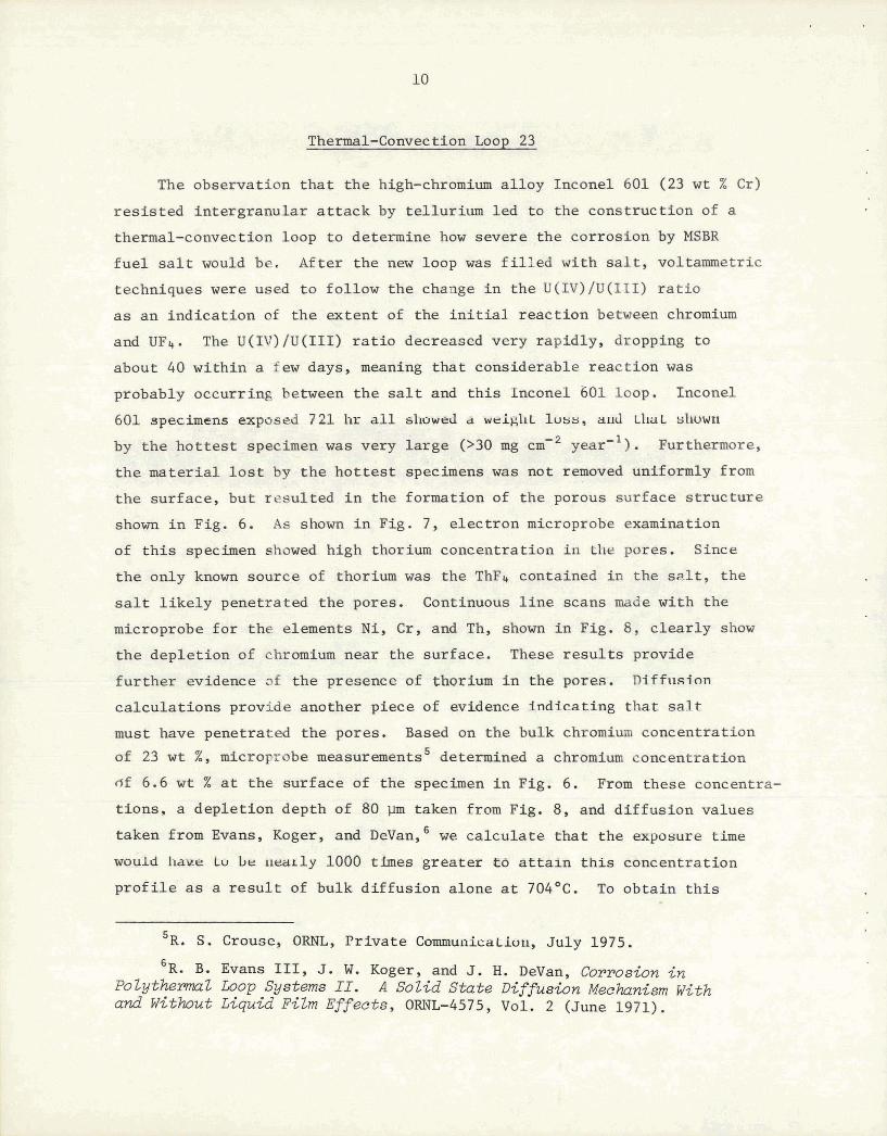
Thkr@+kl-Comrect:ion Loop 23
The observation t h a t the high-chromium a l loy Inconel 601 (23 w t % Cr)
r e s i s t ed intergranular a t t ack by tellurium led t o the construction of a
thermal-convection loop t o determine bow severe the corrosion by MSBR
f u e l salt would be. After the new loop was f i l l e d with salt, voltammetric
techniques were used t o follow the change i n the U(IV)/U(III) r a t i o
a s an indicat ion of t he extent of the i n i t i a l react ion between chromium
and UFs. The U(IV)/U(III) r a t i o decreased very rapidly, dropping t o
about 40 within a few days, meaning tha t considerable react ion was
probably occurring between the salt and t h i s Inconel 601 loop. Inconel
605, specimens exposed 7 21 11r a l l sl~owarl a weig11L luua, alld LIML ul~uwn
by the h o t t e s t s p e c a e n w a s very la rge (>30 mg ) . Furthermore,
t he mater ta l l o s t by the ho t t e s t specimens w a s not reraoved uniformJ.y from
the surface, but resul ted i n the formation of the porous surface s t ruc ture
shown i n Fig. 6. A s shown i n Fig. 7, e lectron microprobe examination
of t h i s specimen showed high thorium concentration i n the pores. Since
the only known source of thorium was the ThF4 contained i n the s a l t , the
s a l t l i k e l y penetrated the pores. Continuous l i n e scans made with the
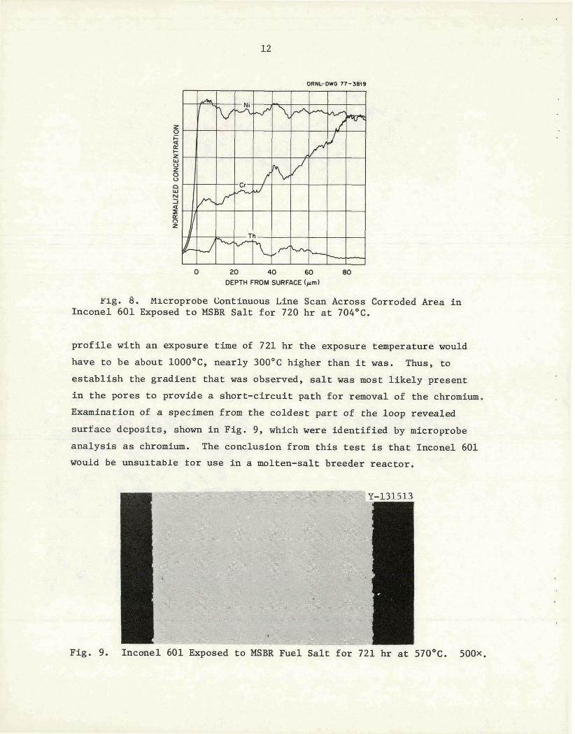
microprobe f o r the elements N i , C r , and Th, shown i n Fig. 8, c lear ly show
the depletion of chromium near the surface. These r e su l t s provide
fur ther evidence of the presence of thorium i n the pores. lliffnsian
calculat ions provide another piece of evidence indicating t h a t s a l t
must have penetrated the pores. Based on the bulk chromium concentration
of 23 w t %, microprobe measurements5 determined a chromium concentration
df 6.6 w t X a t the surface of the specimen i n Fig. 6. From these concentra-
t ions , a depletion depth of 80 pm taken from Fig. 8, and diffusion values
taken from Evans, Koger, and DeVan, we ca lcu la te t h a t the exposure time
would 11awa Lo be nearly 1000 times greater a0 a t t a i n t h i s con cent ratio^
p r o f i l e a s a r e s u l t of bulk diffusion alone a t 704OC. To obtain t h i s
'R. S. Grouse, ORNL, Pr iva te ConununicaLion, July 1975.
6 ~ . B. Evans 111, J. W. Koger, and J. H. DeVan, Cormswn i n PoZythemZ b o p Systems II. A Sol id S t a t e Di f f~s ion Mechanism With and Without Liquid Film Effects, ORNL-4575, Vol. 2 (June 1971).
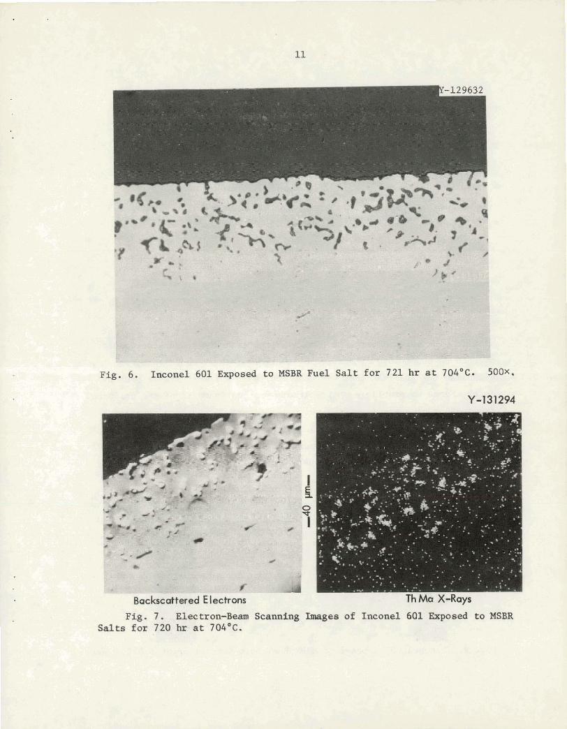
Fig. 6. Inconel 601 Exposed to MSBR Fuel Salt for 721 hr at 704OC- 500x.
Y-t3$294
PQ. 7, . . ~ ~ ~ ; x o P ~ Scamhg mea, of frisconel e3f ucsd t o lS3R Salts fm ?,SO. &- at 704'C.
0 20 40 60 80 DEPTH FROM SURFACE (pm)
~ l g , 8. Microprobe Continuous Line Scan Across Corroaea Area i n Inconel 601 Exposed t o MSBR Sal t f o r 720 h r a t 704'~.
p r o f i l e with an exposure time of 721 h r the exposure temperature would
have t o be about 1000°C, nearly 300°C higher than it was. Thus, t o
e s t ab l i sh the gradient t h a t was observed, salt was most l i k e l y present
i n the pores t o provide a short -c i rcui t path f o r removal of the chromium.
Examination of a specimen from the coldest par t of the loop revealed
surface deposits , shown i n Fig. 9, which were ident i f ied by microprobe
ana lys i s as chromium, The conclusion from t h i s test is that Inconel 601
would be utirjluitabLe t o r use i n a molten-salt breeder reactor.
Fig. 9. Inconel 601 Exposed t o MSBR Fuel Sa l t f o r 721 hr at 570°C. 5 0 0 ~ .
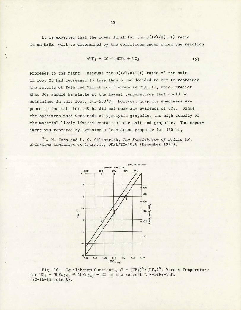
It i s expected t h a t the lower l i m i t f o r the U(IV)/U(III) r a t i o
i n an MSBR w i l l be determined by the conditions under which t he reac t ion
proceeds t o the r i gh t . Because the U(IV)/U(III) r a t i o of the salt
i n loop 23 had decreased to less than 6, w e decided t o t r y t o reproduce
the r e s u l t s of Toth and Gilpatrick, ' shown i n Fig. 10, which predict
that UC2 should be s t ab l e a t the lowest temperatures that could be
maintained i n t h i s loop, 545-550°C. However, graphi te specimens ex-
posed to the s a l t f o r 530 hr did not show any evidence of UC2. Since
the specimens used were made of pyrolyt ic graphite, t he high density of
the mater ia l l i k e l y l imited contact of t he s a l t and graphite. The exper-
iment was repeated by exposing a l e s s dense graphi te f o r 530 h r ,
'L. M. Toth and L. 0 . Gilpatrick, The E&Zibriwn of DiZute UF3 SoZutions Contained i n Graphite, 0 ~ ~ ~ / l ' M - 4 0 5 6 (December 1972).
OIYL-WO TEMPERATURE (-1
!m 6 0 0 6 5 0 I O D
Fig. 10. Equilibrium Quotients, Q = (w~) ' / (uFI , )~ , Versus Temperature f o r UC2 + 3UF&(d) ' 4UF3(d) + 2C i n the Solvent LiF-BeF2-ThF4 (72-1 6-12 mole $ 1 .
then checking the graphi te surface for the presence of a new phase by
x-ray d i f f r ac t ion . A new phase was found, and it was t en ta t ive ly ident i -
f i ed by 0. B. Cavin a s UOn. I f indeed t h i s compound was U02, i t probably
resu l ted from a uranium fluoride-water reaction, but it could have come
from the hydrolysis of UC2 tha t had been formed by react ion (5). On
the bas i s of information from L. M. ~ 0 t h ' t h a t nucleation of UC2 under
our operating conditions could be very slow, a longer exposure was
undertakdn. Two specimens of the l e s s dense graphite were exposed f o r
about 3000 hr a t a minimum temperature of 555°C i n salt i n which the
U(IV)U/(~II) r a t i o had dropped to about 4. However, x-ray analysis o t
these specimens showed no evidence of a phase other than the salt and
graphite. Ho fur ther investigations were carried out h e r ~ l i ~ e nf t h e
termination of the program.
Thermal-Convection Loop 31
Thermal-convection loop 31 is constructed of type 316 s t a in l e s s steel,
has type 316 s t a i n l e s s steel specimens, and has been used f o r corrosion
measurements with one of the a l t e rna t ive coolant s a l t s , LiF-BeF2
(66-34 mole %). For the f i r s t 1000 hr of operation t h i s loop w a s used
t o gather base-line corrosion da ta with as-received s a l t , which contained
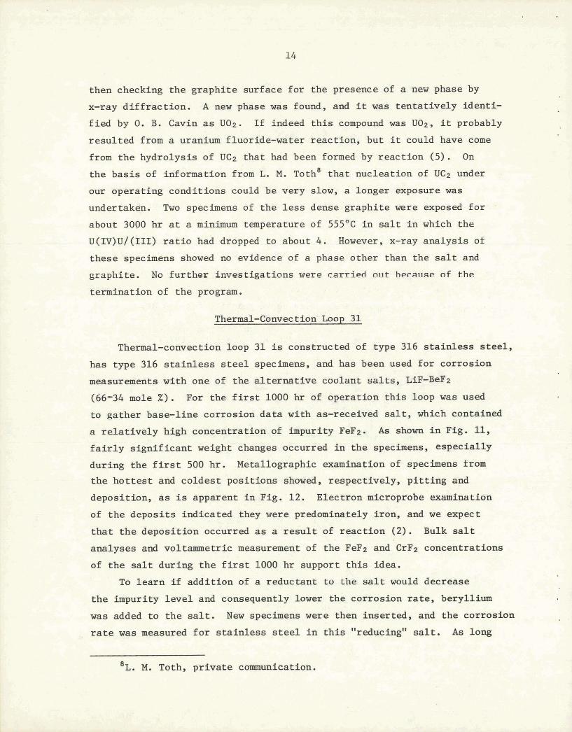
a r e l a t i ve ly high concentration of impurity FeF2. A s shown i n Fig. 11,
f a i r l y s ign i f ican t weight changes occurred i n the specimens, especial ly
during the f i r s t 500 hr . Metallographic examination of specimens from
the ho t t e s t and coldest posit ions showed, respectively, p i t t i n g and
deposition, as is apparent I n Fig. 12. Electron microprobe examination
of t he deposi ts indicated they were predominately iron, and we expect
t h a t t he deposit ion occurred a s a r e s u l t of react ion (2). Bulk s a l t
analyses and voltammetric measurement of the FeF2 and CrF2 concentrations
of the s a l t during the f i r s t 1000 h r support t h i s idea.
To l ea rn i f addi t ion of a reductant t o the s a l t would decrease
the impurity l e v e l and consequently lower the corrosion r a t e , beryllium
was added t o t he s a l t . New specimens w e r e then inserted, and the corrosion
rate w a s measured f o r s t a in l e s s steel i n t h i s "reducing" s a l t . A s long
'L. M. Toth, p r iva te commmication.
8 . L l .lf
, , "-,I - : - ',-: . i, , ..Lk:=R,r .;,.,=-..
. . "Ii\ - '.', - .- -
I...
ui
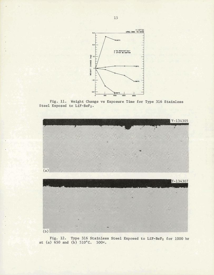
F i g . 11. Weight Change vs Exposure Time for Type 316 Stainless Steel Exposed to LiF-BeF2.
PSg. 12. w e 316 ~ t & h e Weal Ekposad to M~~ f a Z@OO hr at (a3 650 aml (b) 520"G. SOOX.
a s t he beryllium rod was i n t he s a l t , the corrosion r a t e was extremely
low. This is shown i n Fig. 11 fo r the f i r s t 500 hr a f t e r the addi t ion
of beryllium. After removal of the beryllium, the specimen i n the ho t t e s t
pos i t ion showed a pa t te rn of increasing weight l o s s a s a function of
time. This most probably occurred because, once the source of beryllium
was removed, the species i n t he s a l t were no longer i n equilibrium and
the salt became progressively more oxidizing with increasing time,
espec ia l ly a s moisture would leak in to the system. Weight change r e s u l t s
f o r specimens exposed t o the "reducing" s a l t a r e a l so shown i n Fig. 11.
Thermal-Convection Loops 18C and 24
Hastelloy N loops 18C and 24 were used t o determine the e f f ec t of
chromium concentration on the corrosion r a t e of Hastelloy N. Alloys
such a s s t a in l e s s steels and Inconels with a r e l a t i ve ly high chromium
content had shown a res i s tance t o gra in boundary a t t ack by tellurium
t h a t seemed t o be roughly proportional t o chromium composition. However,
increasing the chromium content is, according to Eq. (4), expected to
increase the corrosion t h a t w i l l occur because of mass transfer , From
these tests and tellurium exposure t e s t s we hoped to l ea rn i f there
is a n optimum chromium concentration. Specimens were fabricaced from
modified Hastelloy N a l l oys containing 7, 10, and 12% Cr . Each s e t of
specimens w a s exposed i n one of the loops fo r a t o t a l of 1000 hr , with
weight change measured a f t e r 500 and 1000 hr . Within experimental e r ror
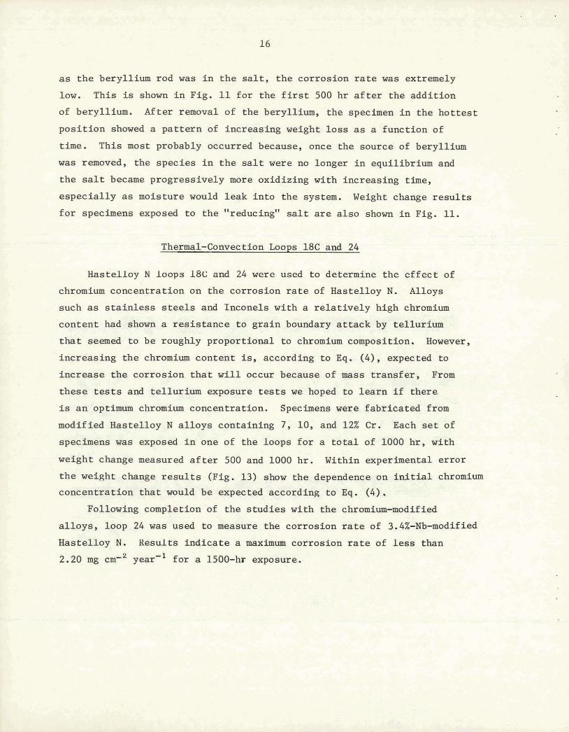
t he weight change r e s u l t s (Fig. 13) show the dependence on i lu l t i a l chromium
concentration t h a t would be expected according t o Eq, (4). Following completion of the s tud ies with the chromium-modified
a l loys , loop 24 w a s used t o measure the corrosion rate of 3.4%-Nb-modified
Hastelloy N. Results ind ica te a maximum corrosion r a t e of l e s s than
2.20 mg cm-2 year'1 f a r a 1500-hr exposure.
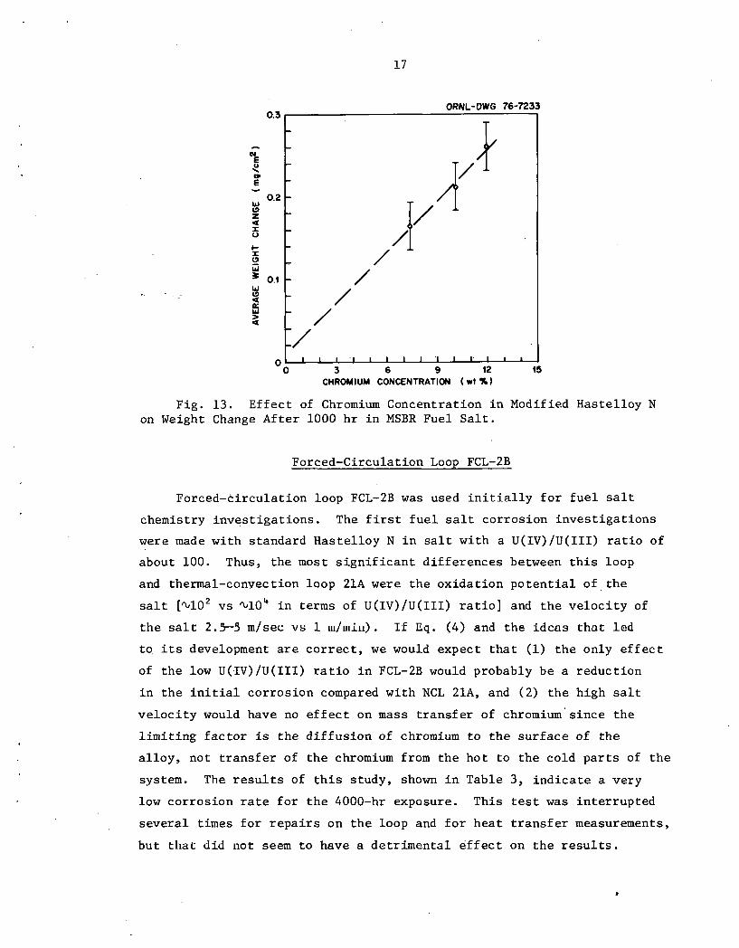
Fig . 13. E f f e c t of Chromium Concentrat ion i n Modified Has te l loy N on Weight Change A f t e r 1000 h r i n MSBR Fuel S a l t .
ORNL-DWG 76-7233
Forced-Circulat ion Loop FCL-2B
0.3
- N E Q : - W
0.2 (3 z a I U
I- x !? W
0.1 W (3 a P: W > a
0
Forced-c i rcu la t ion loop FCL-2B was used i n i t i a l l y f o r f u e l sal t
chemistry i n v e s t i g a t i o n s . The f i r s t f u e l sal t co r ros ion i n v e s t i g a t i o n s
were made wi th s tandard Has t e l loy N i n s a l t w i th a U(IV)/U(III) r a t i o of
about 100. Thus, t h e most s i g n i f i c a n t d i f f e r e n c e s between t h i s loop
and thermal-convection loop 21A were t h e o x i d a t i o n p o t e n t i a l of t h e
salt [$lo2 vs $lo4 i n terms of U(IV)/U(III) r a t i o ] and t h e v e l o c i t y of
t h e s a l t 2. S-5 mlsec vs 1 lu/uliu) . I f Eq. (4) and t h e i d c a s t h a t l c d
t o i t s development a r e c o r r e c t , we would expect t h a t (1) t h e only e f f e c t
of t h e low U(IV)/U(III) r a t i o i n FCL-2B would probably be a r educ t ion
i n t h e i n i t i a l c o r r o s i o n compared wi th NCL 21A, and ( 2 ) t h e h igh salt
v e l o c i t y would have no e f f e c t on mass t r a n s f e r of chromium'since t h e
l i m i t i n g f a c t o r is t h e d i f f u s i o n of chromium t o t h e s u r f a c e of t h e
a l l o y , no t t r a n s f e r of t h e chromium from t h e h o t t o t h e co ld p a r t s of t h e
system. The r e s u l t s of t h i s s tudy, shown i n Table 3, i n d i c a t e a very
low co r ros ion r a t e f o r t h e 4000-hr exposure. This t e s t was i n t e r r u p t e d
s e v e r a l t imes f o r r e p a i r s on t h e loop and f o r h e a t t r a n s f e r measurements,
b u t trl~ac d id not seem t o have a de t r imen ta l e f f e c t on t h e r e s u l t s .
- - - - - - - - / 1' 4 - / - / - - / /
I/ l l l l l l I 1 l l t l r l
0 3 6 9 12 15 CHROMIUM CONCENTRATION ( w t %)
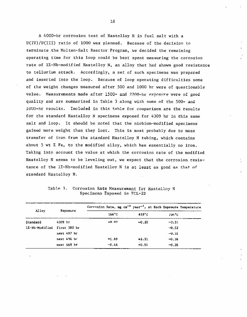
A 4000-hr c o r r o s i o n t e s t of Has t e l loy N i n f u e l s a l t with a
U(IV)/U(III) r a t i o of 1000 w a s planned. Because of t h e dec i s ion t o
t e rmina te t h e Molten-Sal t Reactor Program, we decided t h e remaining
o p e r a t i n g t ime f o r t h i s loop could be b e s t spent measuring t h e co r ros ion
r a t e of 1%-Nb-modified Has t e l loy N , an a l l o y t h a t had shown good r e s i s t a n c e
t o t e l l u r i u m a t t a c k . Accordingly, a s e t of such specimens was prepared
and i n s e r t e d i n t o t h e loop . Because of loop ope ra t ing d i f f i c u l t i e s some
of t h e weight changes measured a f t e r 500 and 1000 h r were of ques t ionab le
v a l u e . Measurements made a f t e r 1500- and 3.7n0-hr ~ x p n s i i r e were of good
q u a l i t y and a r e summarized i n Table 3 along wi th some of the 500- and
IUUU-hr r e s u l t s . Included i n t h i s tahle f o r co l~~pa r i son a r e the r e s u l t s
f o r t h e s tandard Has t e l loy N specimens exposed f o r 4309 h r i n t h i s same
s a l t and loop . It should be noted t h a t t h e niobium-modified specimens
gained more weight than they l o s t . This is most probably due t o mass
t r a n s f e r of i r o n from t h e s tandard Has t e l loy N tubing, which con ta ins
about 5 w t % Fe, t o t h e modif ied a l l o y , which has e s s e n t i a l l y no i r o n .
Taking i n t o account t h e v a l u e a t which t h e c o r r o s i o n r a t e of t h e modified
H a s t e l l o y N seems t o be l e v e l i n g o u t , we expect t h a t t h e co r ros ion r e s i s -
t a n c e of t h e 1%-Nb-modified Has t e l loy N is a t leas t as good as that nf
s t anda rd Has t e l loy N .
Table 3 . Corrosion Rate Measurement f o r Hastelloy N Specimens Exposed i n FCL-2D
Cnrrnsinn F.ate, mg cm'* a t Each Expeaurs Temperature Alloy Exposure
566°C E35'C '/U4 O C
Standard 4309 hr
1%-Nb-Modified first 580 hr
next 497 hr
nex t 496 111-
next 669 hr
CONCLUSIONS
The fo l lowing conclus ions can be drawn from t h i s work.
1. Voltammetry provides a very convenient means f o r on- l ine
measurement of t h e o x i d a t i o n p o t e n t i a l and impuri ty concen t r a t ion of
t h e s a l t . 2. Inconel 601 would probably no t have s u f f i c i e n t co r ros ion
r e s i s t a n c e t o be accep tab le f o r u s e a s a containment v e s s e l m a t e r i a l .
3. No evidence of t h e formation of uranium c a r b i d e was found
i n s t u d i e s of t h e r e a c t i o n of g r a p h i t e w i th very reducing salt .
4 . Weight l o s s of Has te l loy N specimens occurred a s a l i n e a r
func t ion of t h e square r o o t of t h e exposure t ime i n d i c a t i n g d i f f u s i o n -
c o n t r o l l e d co r ros ion .
5. Type 316 s t a i n l e s s s t e e l has a h igh i n i t i a l co r ros ion r a t e
i n as-received Li2BeFk, b u t has a very low c o r r o s i o n r a t e when bery l l ium
is added t o t h e s a l t .
6. Alloys of Has t e l loy N modified by t h e a d d i t i o n of chromium
showed weight l o s s e s p ropor t iona l t o t h e chromium concen t r a t ion .
7 , Limited r e s u l t s i n d i c a t e t h a t t h e c o r r o s i o n r a t e s of 1- and
3.4%-Nb-modified Has t e l loy N a r e a t l e a s t a s good a s t h a t of s tandard
Has te l loy N.
ACKNOWLEDGMENTS
The au tho r wishes t o g r a t e f u l l y acknowledge t h e fo l lowing persons;
f o r t h e i r c o n t r i b u t i o n s ; E. J. Lawrence f o r o p e r a t i o n of t h e thermal-
convect ion loops , W. R . Huntley and H. E . Robertson f o r o p e r a t i o n of
t h e fo rced -c i r cu la t ion loop, H. E. McCoy, J . R. DiStefano, .and J. H. DeVan
f o r t h e i r adv ice and h e l p f u l d i scuss ions , and S. Pe t e r son f o r e d i t i n g
and Ga i l Go l l ihe r f o r prepar ing t h e manuscript .

THIS PAGE.
WAS INTENTIONALLY ' .
LEFT BLANK
ORNLITM-5783 Distribution Category UC-76
INTERNAL DISTRIBUTION
Central Research Library Document Reference Section Laboratory Records Department Laboratory Records, ORNL RC ORNL Patent Office C. F. Baes C. E. Bamberger E. S. Bettis C. R. Brinkman J. Brynestad D. A. Canonico S. Cantor C. B. Cavin R. E. Clausing J. L. Crowley F. L. Culler J. E. Cunningham J. H. DeVan J. R. DiStefano, R. G. Donnelly J. R. Engel L. M. Ferris G. M. Goodwin W. R. Grimes R. H. Guymon J. R. Hightower, Jr. M. R. Hill W. R. Huntley J. R. Keiser
A. D. Kelmers R, E. MacPherson G. Mamantov D. L. Manning C. L. Matthews L. Maya H. E. McCoy C. J. McHargue L. E. McNeese H. Postma T. K. Roche M. W. Rosenthal H. C. Savage J. E. Selle M. D. Silverman G. M. Slaughter A. N. Smith .
L. M. Toth D. B. Trauger J. R. Weir, Jr. C. L. White J. P. Young R. W. Balluffi (consultant) P. M. Brister (consultant) W. R. Hibbard, Jr. (consultant) Hayne Palmour I11 (consultant) N. E. Promise1 (consultant) D. F. Stein (consultant)
EXTERNAL DISTRIBUTION
74-80. ERDA OAK RIDGE OPERATIONS OFFICE, P. 0. Box E, Oak Ridge, TN 37830 ,
Director, Reactor Diyision Research and'Technica1 Support Division
81-82. ERDA DIVISION OF NUCLEAR RESEARCH AND APPLICATION, Washington, DC 20545
Director
83--196. ERDA TECHNICAL INFORMATION CENTER, Office of Information Services, P. 0. Box 62, Oak Ridge, TN 37830
For distribution as shown in TID-4500 Distribution Category, .
UC-76 (Molten Salt Reactor Technology);
a US. GOVERNMENT PRINTING OFFICE: 1977-748-189/54