compensation of transient beam-loading in clic main linac oleksiy kononenko, alexej grudiev iwlc,...
TRANSCRIPT
Compensation of Transient Beam-Loading in CLIC Main Linac
Oleksiy Kononenko, Alexej Grudiev
IWLC, October 20, 2010
Contents
• Motivation• Calculation of unloaded/loaded voltages • Optimization of the pulse shape• Spread minimization for BNS damping and
transient in the subharmonic buncher• Effects of the charge jitters in drive and main
beams• Conclusions
Motivation: CLIC Performance Issue
*CLIC-Note-764, private conversations with Daniel Schulte (CERN)
In order to have luminosity loss less than 1%, the RMS bunch-to-bunch relative energy spread must be below 0.03%
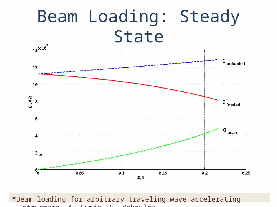
Beam Loading: Steady State
0 0.05 0.1 0.15 0.2 0.250
2
4
6
8
10
12
14x 10
7
z, m
G, V
/m
Gloaded
Gunloaded
Gbeam
20
*Beam loading for arbitrary traveling wave accelerating structure. A. Lunin, V. Yakovlev
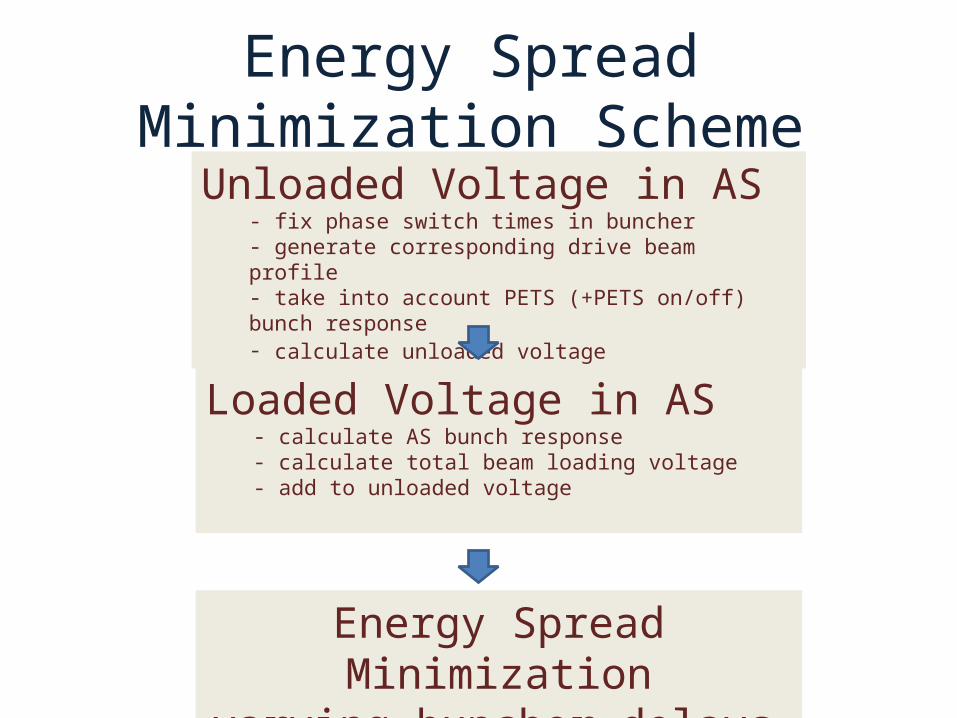
Energy Spread Minimization Scheme
Klystron (reference) pulse
Unloaded Voltage in AS- fix phase switch times in buncher- generate corresponding drive beam profile- take into account PETS (+PETS on/off) bunch response- calculate unloaded voltage
Loaded Voltage in AS - calculate AS bunch response - calculate total beam loading voltage- add to unloaded voltage
Energy Spread Minimizationvarying buncher delays
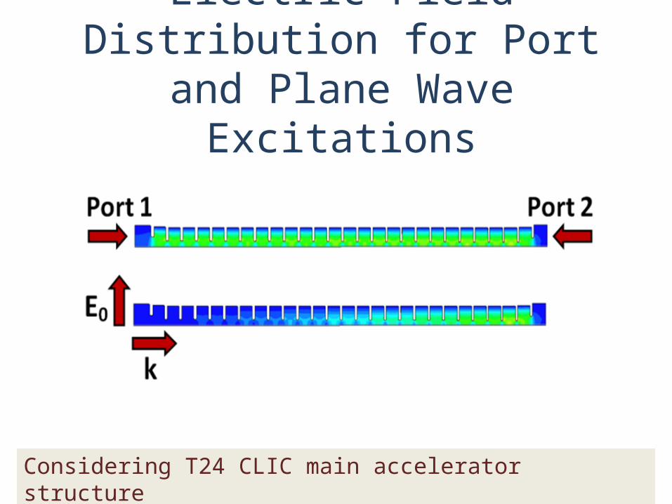
Electric Field Distribution for Port and Plane Wave Excitations
Considering T24 CLIC main accelerator structure
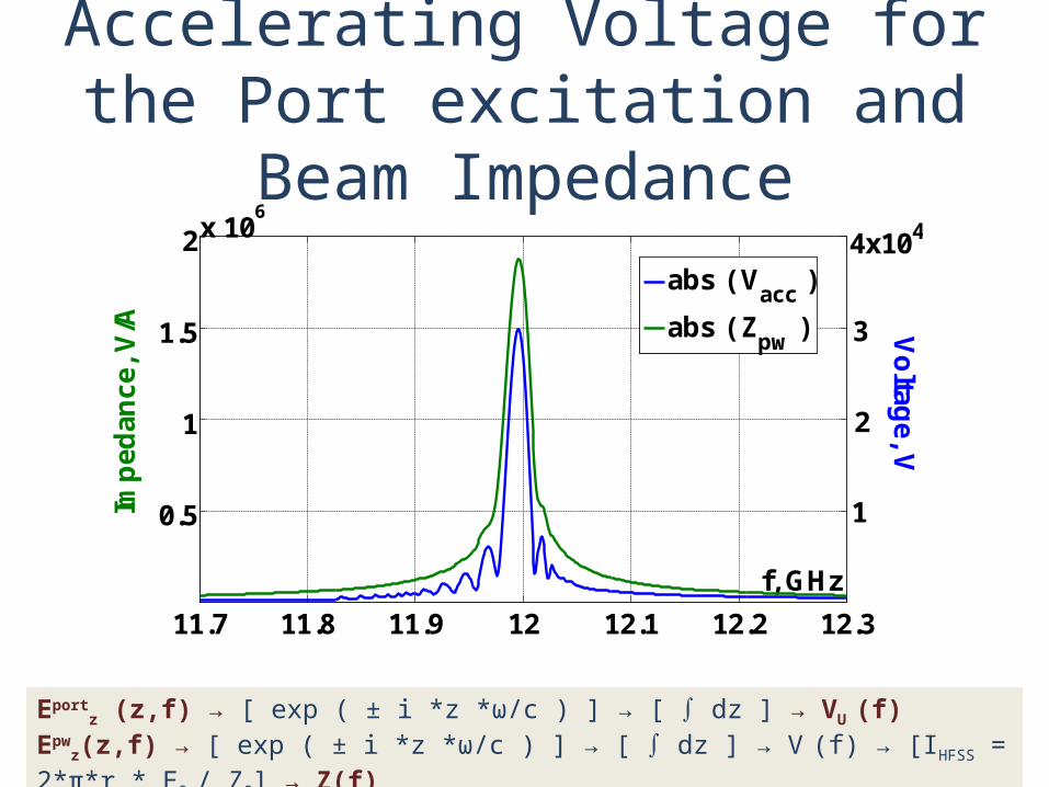
Accelerating Voltage for the Port excitation and Beam Impedance
Eportz (z,f) → [ exp ( ± i *z *ω/c ) ] → [ ∫ dz ] → VU (f)
Epwz(z,f) → [ exp ( ± i *z *ω/c ) ] → [ ∫ dz ] → V (f) → [IHFSS = 2*π*r * E0 / Z0] → Z(f)
11.7 11.8 11.9 12 12.1 12.2 12.3
0.5
1
1.5
2x 10⁶
f, GHz
Imp
edan
ce, V
/A Vo
ltage, V
abs ( Vacc
)
abs ( Zpw
)
1
2
3
4x10⁴
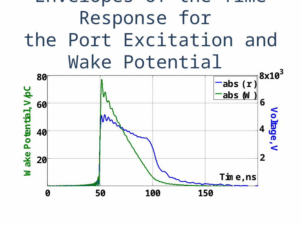
Envelopes of the Time Response for the Port Excitation and Wake Potential
0 50 100 150
20
40
60
80
Time, nsWak
e P
ote
nti
al, V
/pC
Vo
ltage, V
abs ( r )abs (W)
8x10³
6
4
2
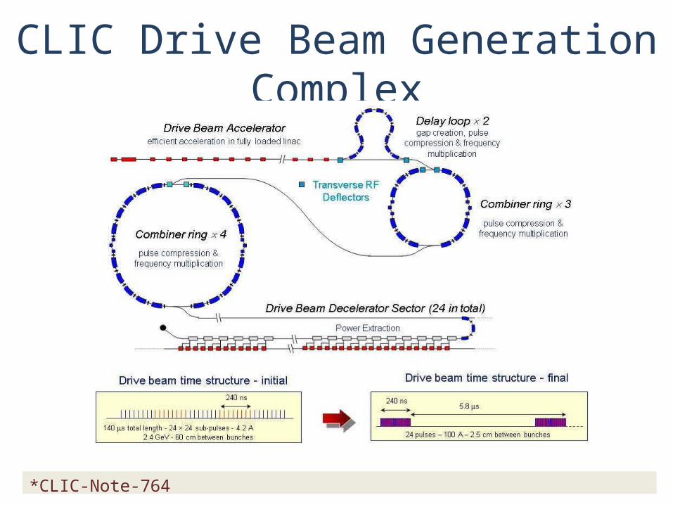
CLIC Drive Beam Generation Complex
*CLIC-Note-764
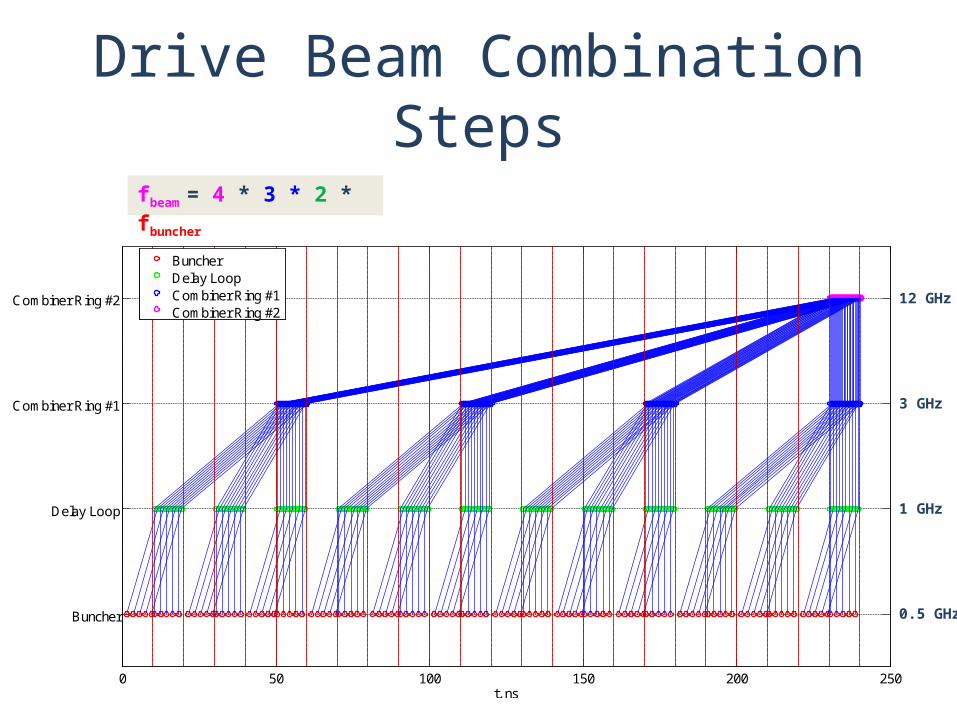
Drive Beam Combination Steps
0 50 100 150 200 250
Buncher
Delay Loop
Combiner Ring #1
Combiner Ring #2
t, ns
BuncherDelay LoopCombiner Ring #1Combiner Ring #2
fbeam = 4 * 3 * 2 * fbuncher
12 GHz
3 GHz
1 GHz
0.5 GHz
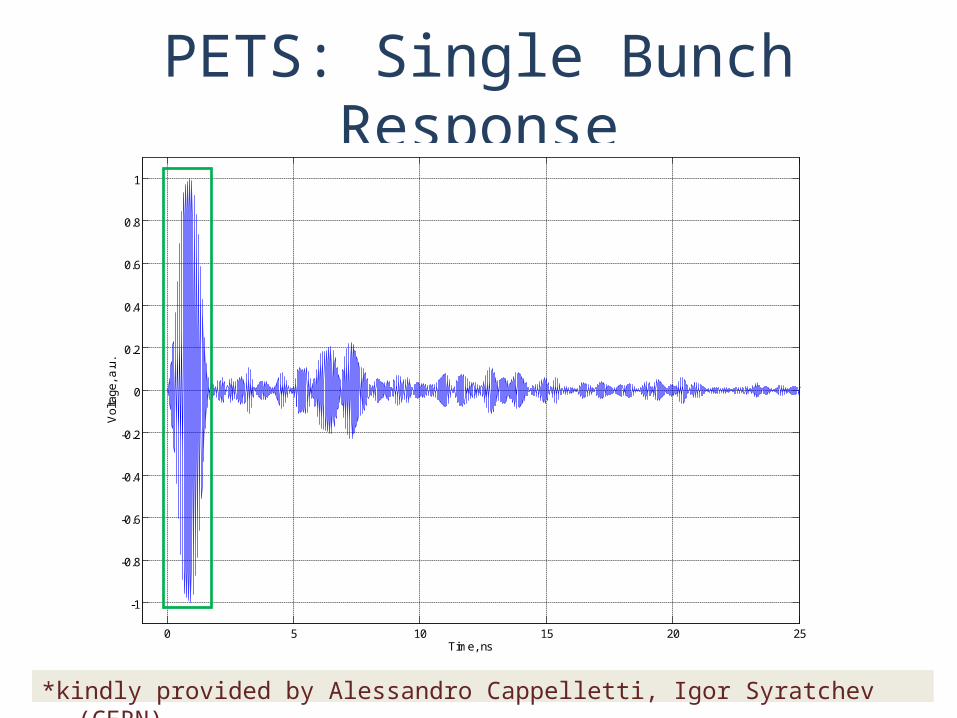
PETS: Single Bunch Response
0 5 10 15 20 25
-1
-0.8
-0.6
-0.4
-0.2
0
0.2
0.4
0.6
0.8
1
Time, ns
Vol
tage
, a.u
.
*kindly provided by Alessandro Cappelletti, Igor Syratchev (CERN)
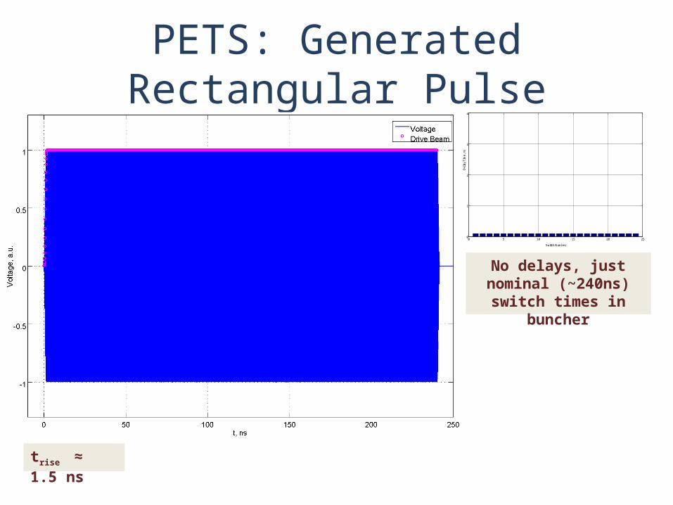
PETS: Generated Rectangular Pulse
trise ≈ 1.5 ns
0 5 10 15 20 250
1
2
3
4
Switch Number
Del
ay T
ime,
ns
No delays, just nominal (~240ns) switch times in
buncher
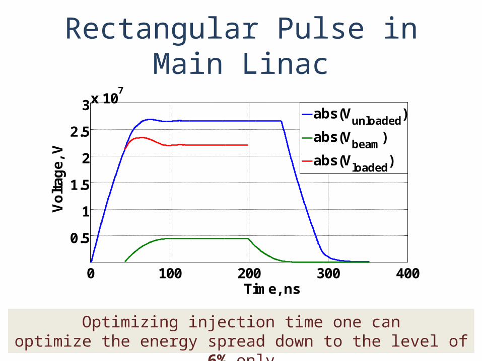
Rectangular Pulse in Main Linac
Optimizing injection time one canoptimize the energy spread down to the level of 6% only
0 100 200 300 400
0.5
1
1.5
2
2.5
3x 10⁷
Time, ns
Vo
ltag
e, V
abs(Vunloaded
)
abs(Vbeam
)
abs(Vloaded
)
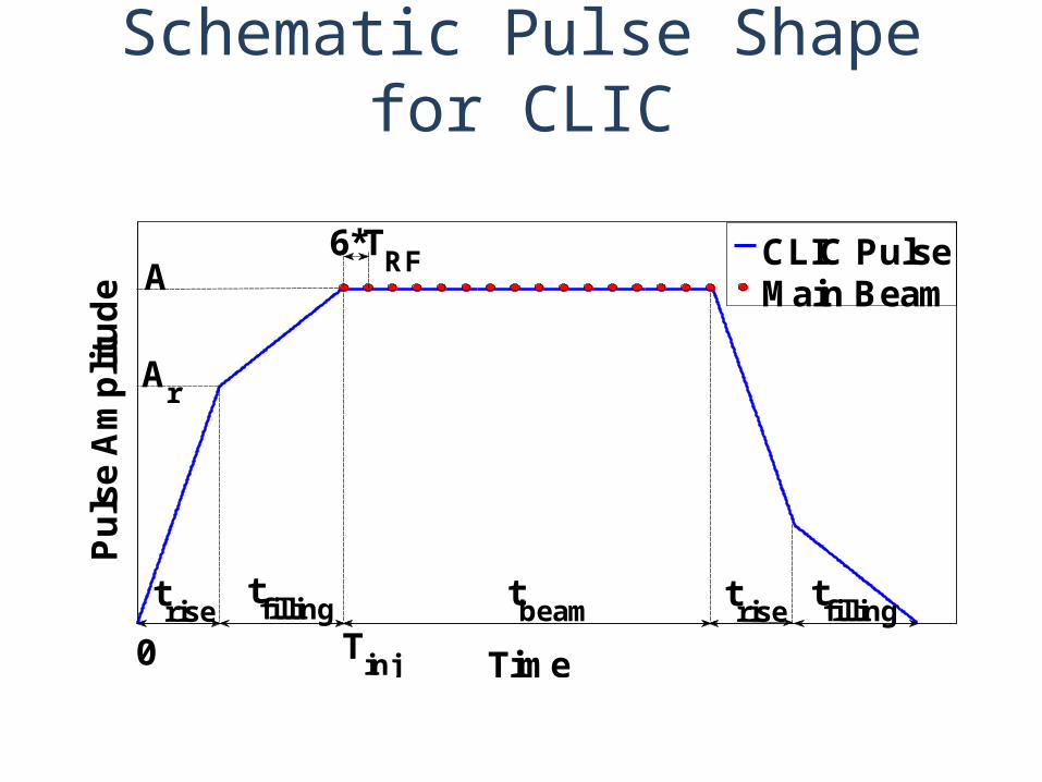
Schematic Pulse Shape for CLIC
Time
Pu
lse
Am
plit
ud
e
CLIC Pulse Main BeamA
Ar
6*TRF
trise
tfilling t
beamtrise
0 Tinj
tfilling
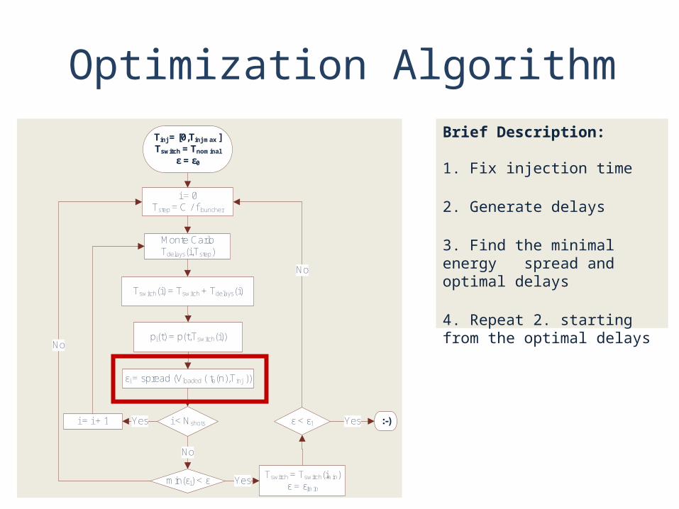
Optimization AlgorithmBrief Description:
1. Fix injection time
2. Generate delays
3. Find the minimal energy spread and optimal delays
4. Repeat 2. starting from the optimal delays
Monte Carlo Tdelays(i,Tstep)
pi(t) = p(t,Tswitch(i))
εi = spread (Vloaded ( tb(n),Tinj ))
i < NshotsYesi = i + 1
No
i = 0Tstep = C / f buncher
Tswitch(i) = Tswitch + Tdelays(i)
min(εi) < ε
No
Tswitch = Tswitch(imin)ε = εimin
Yes
ε < ε1 :-)
Tinj = [0,Tinj max ]Tswitch = Tnominal
ε = ε0
Yes
No
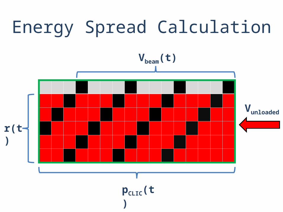
Energy Spread Calculation
r(t)
pCLIC(t)
Vbeam(t)
Vunloaded
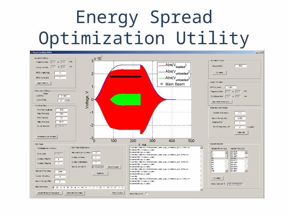
Energy Spread Optimization Utility
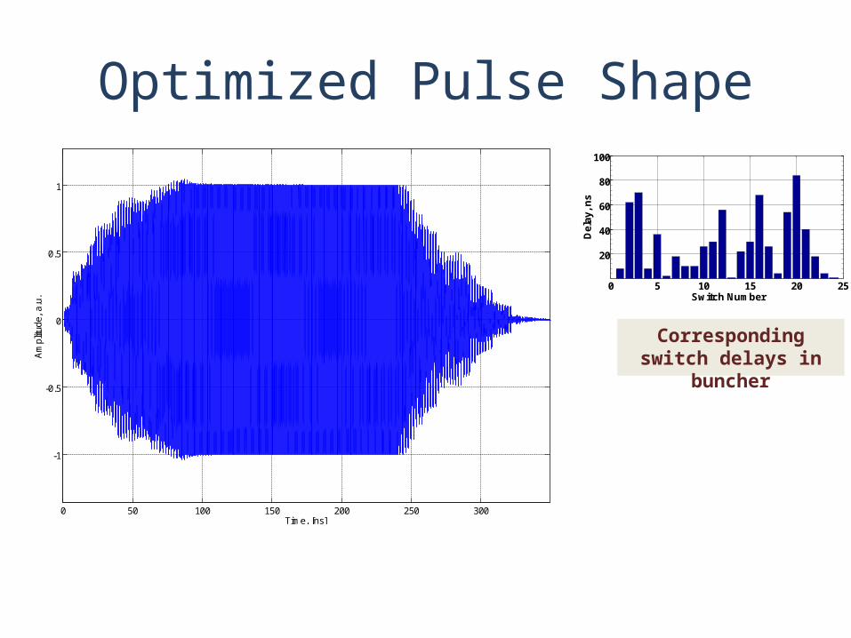
Optimized Pulse Shape
Corresponding switch delays in buncher
0 5 10 15 20 25
20
40
60
80
100
Switch Number
Del
ay, n
s
0 50 100 150 200 250 300
-1
-0.5
0
0.5
1
Time, [ns]
Am
plitu
de,
a.u.
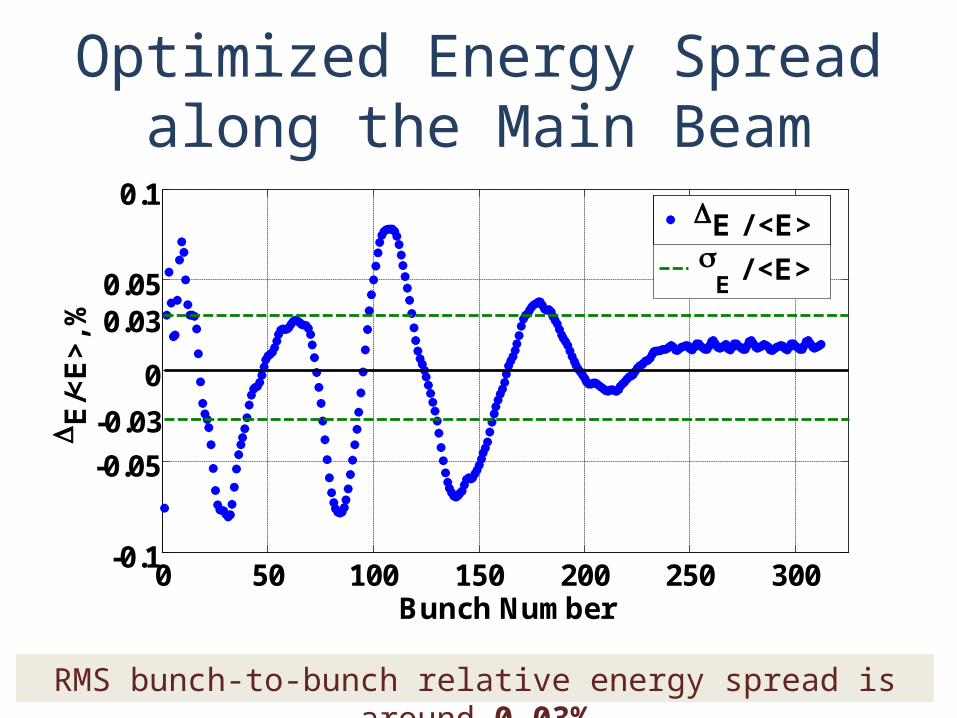
Optimized Energy Spread along the Main Beam
0 50 100 150 200 250 300-0.1
-0.05
0
0.05
0.1
Bunch Number
E
/<E
>, %
E / <E>
-0.03
0.03
E / <E>
RMS bunch-to-bunch relative energy spread is around 0.03%
Model Improvements
1. For BNS damping it is necessary to inject bunches a bit (10 - 30 deg) off-crest
2. Take into account transient in the subharmonic buncher during DB phase switch
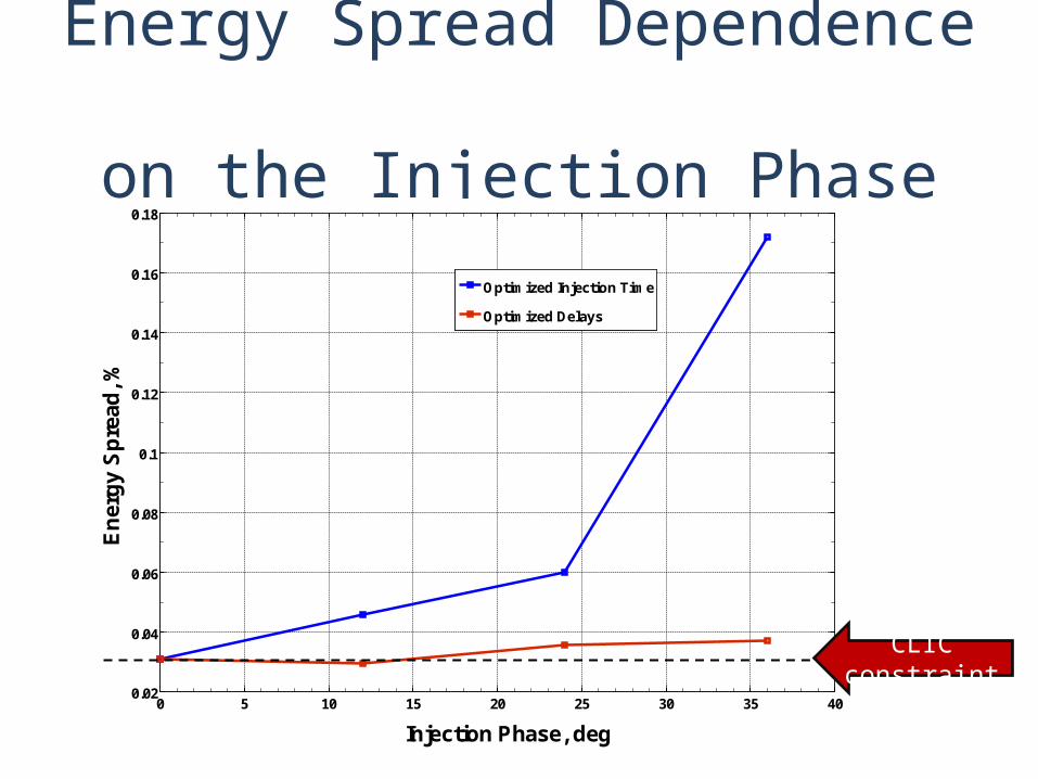
Energy Spread Dependence on the Injection Phase
0 5 10 15 20 25 30 35 400.02
0.04
0.06
0.08
0.1
0.12
0.14
0.16
0.18
Injection Phase, deg
En
erg
y S
pre
ad, %
Optimized Injection Time
Optimized Delays
CLIC constraint
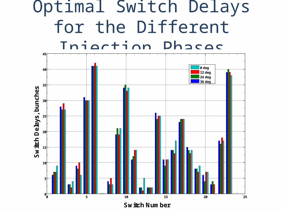
Optimal Switch Delays for the Different Injection Phases
0 5 10 15 20 250
5
10
15
20
25
30
35
40
45
Switch Number
Sw
itch
Del
ays,
bu
nch
es
0 deg12 deg24 deg36 deg
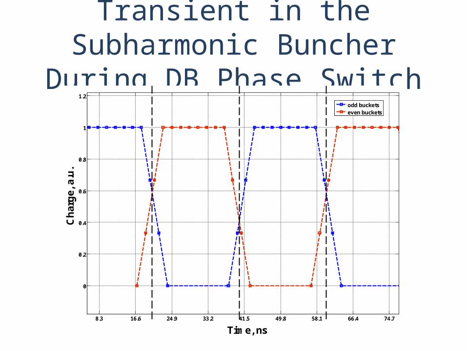
Transient in the Subharmonic Buncher During DB Phase Switch
8.3 16.6 24.9 33.2 41.5 49.8 58.1 66.4 74.7
0
0.2
0.4
0.6
0.8
1
1.2
Time, ns
Ch
arg
e, a
.u.
odd bucketseven buckets
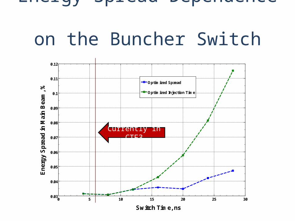
Energy Spread Dependence on the Buncher Switch Time
0 5 10 15 20 25 300.03
0.04
0.05
0.06
0.07
0.08
0.09
0.1
0.11
0.12
Switch Time, ns
En
erg
y S
pre
ad in
Mai
n B
eam
, %
Optimized Spread
Optimized Injection Time
Currently in CTF3
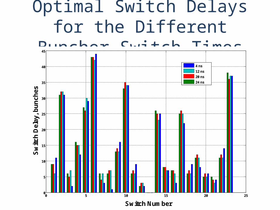
Optimal Switch Delays for the Different Buncher Switch Times
0 5 10 15 20 250
5
10
15
20
25
30
35
40
45
Switch Number
Sw
itch
Del
ay, b
un
ches
4 ns
12 ns
20 ns
24 ns
Study of the Charge JitterInfluence on the Energy Spread
1. Gaussian drive/main beams charge distribution with relative rms spread of 0.1%
2. “White noise” jitter of the charge along the drive/main beams
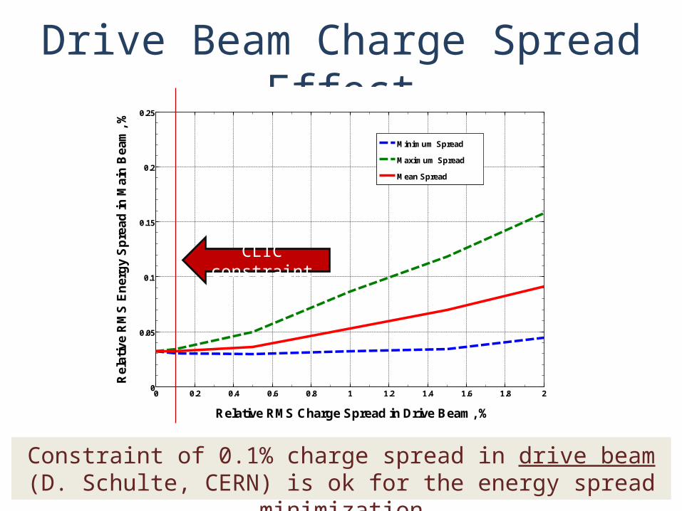
Drive Beam Charge Spread Effect
Constraint of 0.1% charge spread in drive beam (D. Schulte, CERN) is ok for the energy spread minimization
0 0.2 0.4 0.6 0.8 1 1.2 1.4 1.6 1.8 20
0.05
0.1
0.15
0.2
0.25
Relative RMS Charge Spread in Drive Beam, %
Rel
ativ
e R
MS
En
erg
y S
pre
ad in
Mai
n B
eam
, %
Minimum Spread
Maximum Spread
Mean Spread
CLIC constraint
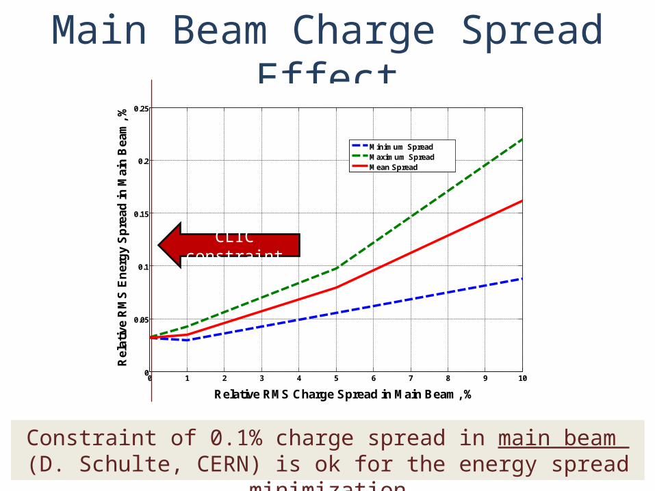
Main Beam Charge Spread Effect
Constraint of 0.1% charge spread in main beam (D. Schulte, CERN) is ok for the energy spread minimization
0 1 2 3 4 5 6 7 8 9 100
0.05
0.1
0.15
0.2
0.25
Relative RMS Charge Spread in Main Beam, %
Rel
ativ
e R
MS
En
erg
y S
pre
ad in
Mai
n B
eam
, %
Minimum SpreadMaximum SpreadMean Spread
CLIC constraint
Conclusions1. Developed pulse shape optimization method allows to reach acceptable
level of 0.03% in the main beam energy spread
2. Performing optimization for the different possible buncher switching times and injection phases the same CLIC acceptable level of energy spread is reached
3. Randomly distributed along the bunch train 0.1% rms spread charge jitters in drive and/or main beams don’t increase the final energy spread in the main beam

Thank You for the Attention!