competition between exceptionally long‐range
TRANSCRIPT

FULL PAPERwww.afm-journal.de
© 2018 WILEY-VCH Verlag GmbH & Co. KGaA, Weinheim1806977 (1 of 13)
Competition between Exceptionally Long-Range Alkyl Sidechain Ordering and Backbone Ordering in Semiconducting Polymers and Its Impact on Electronic and Optoelectronic Properties
Joshua H. Carpenter, Masoud Ghasemi, Eliot Gann, Indunil Angunawela, Samuel J. Stuard, Jeromy James Rech, Earl Ritchie, Brendan T. O’Connor, Joanna Atkin, Wei You, Dean M. DeLongchamp, and Harald Ade*
Intra- and intermolecular ordering greatly impacts the electronic and optoelectronic properties of semiconducting polymers. The interrelationship between ordering of alkyl sidechains and conjugated backbones has yet to be fully detailed, despite much prior effort. Here, the discovery of a highly ordered alkyl sidechain phase in six representative semiconducting polymers, determined from distinct spec-troscopic and diffraction signatures, is reported. The sidechain ordering exhibits unusually large coherence lengths (≥70 nm), induces torsional/twisting back-bone disorder, and results in a vertically multilayered nanostructure with ordered sidechain layers alternating with disordered backbone layers. Calorimetry and in situ variable temperature scattering measurements in a model system poly{4-(5-(4,8-bis(3-butylnonyl)-6-methylbenzo[1,2-b:4,5-b′]dithiophen-2-yl)thiophen-2-yl)-2-(2-butyloctyl)-5,6-difluoro-7-(5-methylthiophen-2-yl)-2H-benzo[d][1,2,3]triazole} (PBnDT-FTAZ) clearly delineate this competition of ordering that prevents simulta-neous long-range order of both moieties. The long-range sidechain ordering can be exploited as a transient state to fabricate PBnDT-FTAZ films with an atypical edge-on texture and 2.5× improved field-effect transistor mobility. The observed influence of ordering between the moieties implies that improved molecular design can pro-duce synergistic rather than destructive ordering effects. Given the large sidechain coherence lengths observed, such synergistic ordering should greatly improve the coherence length of backbone ordering and thereby improve electronic and opto-electronic properties such as charge transport and exciton diffusion lengths.
DOI: 10.1002/adfm.201806977
Dr. J. H. Carpenter, Dr. M. Ghasemi, I. Angunawela, S. J. Stuard, Prof. H. AdeDepartment of Physics and Organic and Carbon Electronics Lab (ORaCEL)North Carolina State UniversityRaleigh, NC 27695, USAE-mail: [email protected]
Dr. E. Gann, Dr. D. M. DeLongchampMaterials Science and Engineering DivisionNational Institute of Standards and Technology100 Bureau Drive, Gaithersburg, MD 20899, USAJ. J. Rech, E. Ritchie, Prof. J. Atkin, Prof. W. YouDepartment of ChemistryUniversity of North Carolina at Chapel HillChapel Hill, NC 27599-3290, USAProf. B. T. O’ConnorDepartment of Mechanical and Aerospace Engineering and ORaCELNorth Carolina State UniversityRaleigh, NC 27695, USA
insulating alkyl sidechains, cause complex and competing phenomena in terms of material phase behavior,[1,2] morphology formation,[3–6] and local ordering,[7–12] that inherently affect material performance. Results in the literature for SCPs that are generally more crystalline and have simpler backbone structures, such as polyakylthiophenes (PATs), demonstrate that ordering in the backbone and πstacking directions are not necessarily strongly correlated with ordering in the alkyl stacking direction or ordering between alkyl sidechains, especially in materials having sufficiently high molecular weight.[13,14] More broadly, it has been shown that phase separation between backbone and alkyl sidechain is a rather general trait among SCPs and that ordering within the alkyl nanodomains can occur even when the nanodomains of the more rigid backbones are amorphous, e.g., in regiorandom PATs.[15,16] Whether sidechains can readily order independently of the aromatic backbones and form separate nanophases when monomer structures and sidechain attachments are highly
asymmetric, as is often the case for amorphous donor–acceptor (D–A) copolymers, is currently an open question.
Studies of ordering in SCPs have shown correlations between backbone ordering and both charge transport and spectroscopic
Organic Electronics
The ORCID identification number(s) for the author(s) of this article can be found under https://doi.org/10.1002/adfm.201806977.
1. Introduction
The two dissimilar constituents of semiconducting polymers (SCPs), the semiconducting conjugated backbone and
Adv. Funct. Mater. 2018, 1806977

www.afm-journal.dewww.advancedsciencenews.com
1806977 (2 of 13) © 2018 WILEY-VCH Verlag GmbH & Co. KGaA, Weinheim
signatures, reflecting aggregation or exciton bandwidth.[13,17–24] In broad qualitative agreement with results from inorganic and organic small molecule semiconductors, much of the early work has shown strong correlations between crystalline order and high charge carrier mobility.[21,25–27] However, for many more recently synthesized SCPs, including many D–Atype copolymers with stiffer backbones, it has been shown that an overall high degree of crystallinity or large crystalline coherence length is not necessary for good charge transport;[13,28,29] instead, the key morphological parameters are torsional backbone order, short range intermolecular order (i.e., aggregation or paracrystalline order), and sufficiently high molecular weight (≥50 mono mer units). Regarding the first factor, the torsional disorder of the backbone, we note that sexithiophene molecules are highly planar within crystals,[30,31] yet in nominal P3HT crystals, backbones are nonplanar with significant distributions of dihedral angles between thiophene units.[32–34] Dihedral angles significantly deviating from coplanarity along the backbone, i.e., backbone disorder, highlight the negative impact sidechains can have and by extension imply an imperfect molecular design that constrains backbone planarity. Additionally, for SCPs having sufficiently high molecular weight, Noriega et al. found that the paracrystallinity parameter (g) in the πstacking direction was ≥6% for a broad crosssection of SCPs.[13] Based on the classifications of SCPs as paracrystalline (g ≈ 6–8%) or amorphous (g ≈ 10–20%) of Noriega et al., many of the more recently synthesized high mobility D–A copolymers are considered to be largely amorphous. This generally observed high degree of paracrystallinity might reflect the competing ordering between sidechains and backbones and does not exclude the possibility
of improving these mobilities further by rationally utilizing sidechain order to induce improvements in backbone order.[35] Such synergistic ordering is an avenue of molecular design that is yet to be explored for alkyl sidechains.
In this work, we report the discovery of a highly ordered alkyl sidechain phase with exceptionally long crystalline coherence length that strongly affects SCP backbone order, optical aggregation, and film microstructure. Films with such sidechain ordering are fabricated by dropcasting from low volatility solvents at room temperature (RT), without any subsequent processing. We characterize the highly ordered sidechain phase and the resulting effects on backbone order and film microstructure in detail using poly{4(5(4,8bis(3butylnonyl)6methylbenzo[1,2b:4,5b′]dithiophen2yl)thiophen2yl)2(2butyloctyl)5,6difluoro7(5methylthiophen2yl)2Hbenzo[d][1,2,3]triazole} (PBnDTFTAZ) as a model system. FTAZ is an amorphous D–A type SCP with g ≈ 15% in πstacking direction and no differential scanning calorimetry (DSC) melting peak >50 °C for typical spincasting processing conditions and solvents. We find that the ordered sidechains in our dropcast films induce significant torsional disorder in the backbone (as observed by spectroscopy), as well as a nanophase composite multilayer consisting of the crystalline insulating sidechain domains and the disordered optoelectronically active backbone domains. Upon melting of the highly ordered sidechain phase, the roughly edgeon backbone configuration remains, yielding inplane (edgeon) πstacking. To visualize the differences, Figure 1b,c illustrates the inferred nanostructure in the FTAZ film with the highly ordered sidechain phase as well as concomitant detrimental effects on backbone ordering as they compare to the ordering present after melting the sidechains in Figure 1d,e. We exploit the
Adv. Funct. Mater. 2018, 1806977
Figure 1. a) Structure of FTAZ. b–e) Conceptualization of the competition in ordering between sidechains and backbones in FTAZ. The long-range 2D crystalline order of the sidechain layers in the drop-cast samples induces torsional disorder in the backbone, preventing intermolecular π-stacking, as shown at an angle in (b) and along the backbone direction in (c). When the highly ordered sidechain phase has melted, the backbones are no longer as torsionally constrained and can π-stack more efficiently, though with a much shorter coherence length than exhibited by the sidechain crystals, as shown at an angle in (d) and along the backbone direction in (e).

www.afm-journal.dewww.advancedsciencenews.com
1806977 (3 of 13) © 2018 WILEY-VCH Verlag GmbH & Co. KGaA, Weinheim
sidechain ordering and the induced backbone order after subsequently melting to improve charge mobility in organic fieldeffect transistors (OFETs) by a factor of 2.5, demonstrating one of many ways this highly ordered sidechain phase could potentially be utilized. We further show that this highly ordered sidechain phase is a general feature of the phase behavior and ordering of a series of SCPs with varying monomer structures, sidechain attachment densities, amounts of sidechain branching, and typical paracrystallinity values. Finally, we hope that our findings can inspire improved material design, where synthetic chemists will utilize this propensity for longrange alkyl sidechain ordering to facilitate similar longrange backbone ordering as a strategy for improving material properties that yields enhanced performance.
2. Results
FTAZ films were dropcast from relatively low volatility solvents, such as chlorobenzene (CB), and left to dry at RT to achieve a very slow solvent quench that increases the ability of the sample to approach local thermodynamic equilibrium and maximizes the degree of sidechain order (see the Experimental Section for details). Spincast samples were also prepared from the same solution for comparison. The samples were investigated with a number of methods, generally investigating first the local bond ordering, then the mesoscopic ordering, and eventually the relationship to thermodynamic transitions.
In order to explore local structural ordering and overall preferred bond orientation at the film surface, we performed nearedge Xray absorption fine structure (NEXAFS) spectroscopy. Total electron yield (TEY) NEXAFS spectra using ppolarized Xrays at varying angles of incidence are shown for FTAZ films dropcast and spincast from CB in Figure 2a,b, respectively, where 90° is normal incidence. From 287 to 290 eV, where C 1s → σ*CH resonances appear both for alkanes and SCPs,[36–40] the dropcast spectra clearly has two peaks at 287.4 and 288.1 eV that are highly dichroic. In neat alkanes this energetic splitting indicates crystallinity because, for alltrans chains, the C 1s → σ*CH transitions are orthogonal to the chain axis to either the lowest unoccupied molecular orbital (LUMO) or LUMO+1, of which the probability densities are predominantly in the plane defined by the chain zigzag or normal to it, respectively[40,41] (for a reproduction of previously published data on nonadecane single crystals that completely reflect the essence of the dropcast data here, see Figure S1 in the Supporting Information). The average transition dipole moment (TDM) of both these transitions together, quantified by a fit to intensity versus incident angle,[36] is oriented 74° from film normal, i.e., highly inplane. This is in strong contrast to the spincast sample, for which there is only a single peak in this region, as is typical for amorphous alkanes,[40] with an average TDM of 57° from normal, very close to the magic angle of 55° which indicates a lack of preferential orientation. These spectral differences signify that, while the sidechains in the spincast sample are amorphous with very little orientational order, the sidechains in the dropcast sample are highly crystalline and highly oriented (for extended discussion of NEXAFS data and fits, see Section S2 in the Supporting Information).
This analysis is confirmed by the C 1s → σ*CC transitions in the 291–296 eV region, with TDMs parallel to the alkyl chain axis direction.[36,37,42] In the dropcast spectra, there are two distinct peaks in this region which mirror the splitting of the CH signature due to the high symmetry of the alltrans conformations of the crystalline sidechains.[40,41,43] These transitions are also highly dichroic, with an average TDM 42° from normal, i.e., tilted, but generally outofplane. The extracted average TDM directions from this spectral region are not as accurate due to background issues such as uncertainty in the signal from the CC bonds in the backbone and C 1s to continuum transitions. Nonetheless, the TDMs for CH and CC
Adv. Funct. Mater. 2018, 1806977
Figure 2. Incident angle dependent TEY NEXAFS spectra of a) drop-cast and b) spin-cast FTAZ using p-polarized X-rays, normalized to 320 eV, where 90° is normal incidence. Insets show full measured energy range. d) Micro-UV–vis spectra of an optically aggregated and nonaggregated region of the drop-cast FTAZ film are shown with c) locations where the spectra were measured shown in a microscopy image.

www.afm-journal.dewww.advancedsciencenews.com
1806977 (4 of 13) © 2018 WILEY-VCH Verlag GmbH & Co. KGaA, Weinheim
are confirmed to be essentially orthogonal as they should be. Note that because of both the branching of the sidechains and the lack of a wellknown global orientation of the molecules, it is not possible to determine the exact average direction of the sidechains from these spectra. In the spincast spectra, there is the typical single C 1s → σ*CC transition, with a calculated average TDM of 57.4° from normal, further demonstrating a lack of sidechain orientational order in the control sample.
Below the C 1s ionization potential at ≈290 eV and the C 1s → σ*CH transitions, the spincast spectra have three clearly observable peaks at 284.5, 285.2, and 286 eV, in agreement with previously published transmission NEXAFS spectra.[44] A fourth peak at 287 eV was necessary to attain a good fit to the spectra that was neither obvious nor noted in previous reports. While detailed assignments of these peaks to specific transitions have not been published for FTAZ, it is well established that materials with thiophene and related aromatic moieties typically have a C 1s → π*CC peak at ≈285.2 eV.[45] Orbital delocalization is commonly attributed with splitting and shifting π* transition intensity into multiple peaks,[46] while substitutions of more electronegative heteroatoms are also known to shift transitions to higher energy relative to materials without the substitutions.[47–49] The peaks in the π* manifold of FTAZ are likely due to a combination of these factors since it has two thiophene units, an FTAZ unit with nitrogen and fluorine heteroatoms, and relatively high charge carrier mobility (and therefore some degree of orbital delocalization between backbone units).
The substantial differences in the C 1s → π*CC transition region from ≈283.5 to 287 eV between spincast and dropcast NEXAFS spectra as well as microUV–vis spectra of the dropcast film demonstrate that the highly ordered sidechains strongly affect the torsional disorder between backbone units and therefore the electronic coupling of the polymer backbone. In the dropcast NEXAFS spectra, the intensity of the lowest energy region of the manifold is increased relative to the rest and there is significant broadening of the peaks relative to those in the spincast spectra, so that their positions are not as clearly defined. When peaks are fit to the dropcast spectra and peak positions allowed to vary, the peak positions shift slightly, though the quality of the fits are comparable to those with the energies held constant. The increased intensity at lower energy relative to the rest of the π* manifold and the substantial overall peak broadening within the manifold of the dropcast spectra are similar to effects reported in P3HT spectra,[50] which were shown to be due to an increase in the range of torsional angles between neighboring backbone units. This interpretation is supported by the dichroism of the π* manifolds, which yielded an average TDM 54.2° from normal for the dropcast film and 46.2° from normal for the spincast film. These differences show that there is no preferential orientation of the π* TDMs in the dropcast film, while FTAZ in the spincast film adopts a more faceon orientation. The microUV–vis spectra in Figure 2d (from a dropcast sample aged at RT for 5 months) provide further evidence of the effect of sidechain crystallinity on electronic coupling. The spectrum measured on an aggregate in the dropcast film (locations shown in Figure 2c) has a clear aggregate optical signature that corresponds to chromophore, i.e., backbone ordering, whereas elsewhere the absorption is featureless, indicating completely disordered backbones
with little optoelectronic coupling between neighboring chromophores. The coexistence in the dropcast film of the two phases with disordered/ordered and ordered/disordered sidechains/backbones, respectively, with an area and thus volume fraction of roughly 50:50 implies that the average NEXAFS TDM orientation discussed above is a mixture of amorphous and nearly perfectly oriented alkane sidechains with a TDM orientation of 33° from film normal for the alkyl chain axis. The NEXAFS spectra of the dropcast sample thus clearly reflect crystalline sidechains and, together with the UV–vis data, demonstrate the resultant effect on backbone torsional ordering.
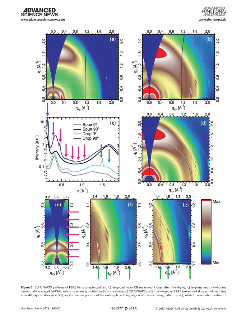
Grazing incidence wide angle Xray scattering (GIWAXS) patterns require longer range ordering than spectroscopic methods to produce a signal and were used for spincast and dropcast FTAZ films (Figure 3a,b, respectively) to help further elucidate the spatial extent of this sidechain ordering and the effect it has on FTAZ backbones and overall microstructure. The GIWAXS pattern of the dropcast sample has a series of relatively intense peaks, very narrow in q, beginning in the inplane direction at qxy = 1.47 Å−1 and corresponding to a real space distance of 4.27 Å, extending in the qz direction with a distinct maximum in intensity for the third peak in qz above qxy = 1.47 Å−1 (features shown zoomedin and highlighted with a green arrow in Figure 3f). The 4.27 Å spacing is within 4% of most reports of the spacing between nearest neighbor chains in short chain (n ≤ 16) nalkane crystals.[51,52] We also note that the third peak in this series in qz also appears very weakly in the spincast film (see Figure 3a,c), which was not annealed or otherwise treated post casting, meaning that it took some time (albeit a considerably shorter period) to fully dry as well. The separation in qz between the peaks in this series corresponds to that of the similarly narrow and also previously unobserved peaks in the outofplane direction at qxy = 0 (features shown zoomedin and highlighted with pink arrows in Figure 3e), beginning at qz = 0.152 Å−1 with at least six diffraction orders visible and measured at exactly qxy = 0 with Xray diffraction (XRD) in θ–2θ geometry (Figure S7, Supporting Information).
The next most significant, if less striking, differences between the scattering patterns from the dropcast and spincast films are between the typical SCP scattering features. There is a noticeable difference in the orientation distribution of the (100) alkyl stacking peak intensity at q ≈ 0.33 Å−1, seen most clearly in the 1D profiles in Figure 3c. The spincast sample has a faceon texture as has been shown previously to be the norm for neat spincast FTAZ films,[53] with a corresponding outofplane πstacking peak (q ≈ 1.68 Å−1). In contrast, the dropcast sample has significantly more (100) intensity outofplane than inplane, importantly, without a commensurate increase in inplane πstacking intensity.
While a full physical description of the exceptional ordering indicated by the scattering pattern of the dropcast samples will require careful further study and is beyond the scope of this paper, we give a brief description here of our interpretation of both the sidechain ordering and the overall microstructure (for extended GIWAXS discussion see Section S3 in the Supporting Information). The sharp peak inplane at q = 1.47 Å−1 in the dropcast pattern signifies very strong ordering inplane of nearest neighbor alkyl sidechains, which are between polymers with backbone axis inplane. Peak widths in qxy correspond to
Adv. Funct. Mater. 2018, 1806977
www.afm-journal.dewww.advancedsciencenews.com
1806977 (5 of 13) © 2018 WILEY-VCH Verlag GmbH & Co. KGaA, WeinheimAdv. Funct. Mater. 2018, 1806977
Figure 3. 2D GIWAXS patterns of FTAZ films a) spin-cast and b) drop-cast from CB measured 7 days after film drying. c) In-plane and out-of-plane azimuthally averaged GIWAXS intensity versus q profiles for both are shown. d) 2D GIWAXS pattern of drop-cast FTAZ (measured at a second beamline after 40 days of storage at RT). e) Zoomed-in portion of the out-of-plane low-q region of the scattering pattern in (b), while f) zoomed-in portion of

www.afm-journal.dewww.advancedsciencenews.com
1806977 (6 of 13) © 2018 WILEY-VCH Verlag GmbH & Co. KGaA, Weinheim
the experimental resolution of beamline 7.3.3 at the Advanced Light Source (ALS) in Figure 3b,e,f, so measurements were also done at beamline 113 at the Stanford Synchrotron Radiation Lightsource (SSRL) (Figure 3d,g, see the Experimental Section for details), where peak widths also corresponded to the experimental resolution and give a lower limit on the coherence length (per single peak Scherrer analysis) inplane between sidechains of 70 nm (>160 intermolecular spacings), an exceptionally large value for SCP ordering. We note that the dropcast sample used for Figure 3d,g was also aged for 40 days at RT which we found, along with increasing solvent boiling point (and therefore drying time), to cause changes in the intensity distribution of some of the sidechain features in azimuthal angle χ. This led to an almost isotropically distributed ring in addition to the more intense, highly oriented scattering features. Changes in peak width of these very sharp peaks with aging could not be determined since at both the beamlines, peak widths were limited by the experimental resolution. The changes in the dropcast scattering patterns with aging at RT were accompanied by observable changes in aggregation with optical microscopy (data not presented here). The exact origin of the spacing indicated outofplane in the dropcast pattern is less clear, as the first order qz value equates to a real space distance of 4.2 nm. The width in qz is also the experimental resolution in this direction, giving a lower limit of the coherence length in this direction of >100 nm (>25 spacings). These peaks at qxy = 0 closely resemble those reported for a spacing in a P3HT “supercell” configuration over multiple backbones and sidechains, which we note appear when films are treated at low temperatures (and therefore potentially involve sidechain ordering).[54] Our data cannot confirm a “supercell” structure for FTAZ and determining the exact packing indicated by these atypical scattering patterns will require further study, however the large size of the observed outofplane spacing implies that it extends across multiple backbones and sidechains. Given that the backbone is disordered in the dropcast sample as observed by the above spectroscopy data, these outofplane peaks do not have a crystallographic unit cell and should be thought of as Bragg diffraction of nanoscale multilayers. This outofplane order, along with both the scattering (marked increase in intensity of the typical outofplane (100) peak with no accompanying increase in inplane πstacking intensity) and spectroscopic evidence for a significant population of disordered backbones in the dropcast sample, suggests a nanophase separated layered morphology with layers of 2D crystalline alkyl sidechains alternating with torsionally disordered backbone layers that are not able to πstack inplane, consistent with the spectroscopy data. The fact that there are several orders of all the alkyl sidechain peaks in the outofplane direction suggests that, despite the torsional disorder along the backbone, there is very good registry between alkyl sidechain layers in this direction over multiple typical (h00) spacings, i.e., across multiple phase separations. We note that changes in the more typical SCP scattering features coinciding
with the highly ordered sidechain features appear to be in addition to scattering features similar to those of the spincast film, indicating a separate population of faceon FTAZ without sidechain ordering and corroborating the image in Figure 2c that indicates two distinct FTAZ populations.
To further study the complex microstructure and longrange alkyl sidechain ordering of FTAZ and its origins, we correlated temperature dependent in situ GIWAXS with DSC thermograms. The GIWAXS patterns were measured from a film dropcast from TCB and measured after aging for 3 days at RT (postdrying) at varying temperature from 35 to 200 °C. The pattern at the first temperature step (35 °C) of the in situ measurements, which shows no significant changes to the scattering pattern yet, is shown in Figure 4a and is very similar to the pattern of the aged sample dropcast from CB and shown in Figure 3d (for all in situ patterns, see Section S4 in the Supporting Information). To best visualize and quantify the changes to the sidechain features with temperature, ±2° cake slices about the direction of the maximum intensity sidechain peak (12° from inplane relative to the beam center) are plotted in Figure 4c,d, to show both the low and high q features, respectively. From peak fits to these 1D profiles, the peak areas of the strongest sidechain peak (≈1.5 Å−1, labeled high q) and the layer spacing peak areas (≈0.15 Å−1, labeled low q) were normalized to their value at 35 °C and plotted in Figure 4e. Both the sets of features show a monotonic and completely simultaneous decrease in relative intensity from 35 to 65 °C and disappear completely at 70 °C. To correlate these diffraction changes to thermodynamic transitions, we overplot the endothermic transitions of samples dropcast from CB and TCB observed in DSC thermographs and find that the disappearance of the diffraction spots are in excellent agreement with the position of the DSC melting peak for the TCB cast film (indicated by a vertical dashed line in Figure 4e). From these data, a coherent picture emerges of crystalline sidechains that melt at ≈50 °C. In pure alkane crystals, this melting temperature would approximately correspond to that of linear ntricosane or ntetracosane (C23H48 or C24H50).[55,56] Given that the sidechains are shorter than the equivalent alkane, we note that one end of the sidechains is pinned due to the backbone attachment reducing possible entropic gains. Since even a doubling of the sidechain lengths would be insufficient to reach the observed melting temperature, we speculate that the sidechain melting is accompanied by a change in the backbone packing that has also an endothermic sign.
The scattering data from 70 to 200 °C provide a structural description of this accompanying change in backbone packing. Over this higher temperature range, there is a clear, dramatic increase in the inplane πstacking peak intensity relative to the rest of the scattering pattern. This coincides with an increase in intensity and narrowing of three orders of conventional outofplane lamellar peaks involving melted or amorphous sidechains. Both the sets of features are shown most clearly in Figure 4b, after the in situ measurements and
Adv. Funct. Mater. 2018, 1806977
the in-plane high-q region of (b). g) The zoomed-in, in-plane high-q portion of (d). In (c), (e), (f), and (g), the green arrows highlight the location of in-plane features in qxy and the pink arrows highlight the location of out-of-plane features in qz. The log intensity color scale (shown) was scaled for each pattern to make the features most visible. The scale has the same values between (b) and (f), but different between (b) and (e).

www.afm-journal.dewww.advancedsciencenews.com
1806977 (7 of 13) © 2018 WILEY-VCH Verlag GmbH & Co. KGaA, Weinheim
cooling back to RT, but the changes can also be observed in each scattering pattern in Section S4 (Supporting Information). This comports with our description above of the frustrated backbone packing originally present in the dropcast samples and illustrated in Figure 1b,c, where the FTAZ backbones with crystalline sidechains are in a roughly edgeon configuration but torsionally disordered such that they are not able to efficiently πstack until after the sidechains melt. We note that the samples that initially exhibited strong sidechain ordering and were annealed above the melting temperature of the sidechains then cooled to RT represent the strongest conventional SCP backbone ordering achieved for FTAZ. Overall, the temperaturedependent data confirm the interpretation of the NEXAFS and UV–vis results described above that the sidechain and backbone ordering are competing and the highly ordered sidechain phase inhibits πstacking between neighboring backbones. Additionally, the increased conventional backbone ordering observed after processing via the melting of the highly ordered sidechain phases also suggests a way to utilize the sidechain ordering in FTAZ to create a microstructure that could be more favorable for inplane charge transport.
Having established the characteristic signatures of this highly ordered sidechain phase and measured its effects, along with those of its subsequent melting, on backbone ordering and film microstructure, we endeavored to exploit this knowledge to improve inplane charge transport properties in OFETs. Based on the in situ variable temperature GIWAXS data, our hypothesis was that inplane charge transport could be improved in dropcast films relative to spincast films by using sidechain ordering to induce a relatively edgeon molecular packing, where the ordered sidechain phase could then be melted to ultimately achieve improved inplane πstacking. In order to test this hypothesis, derived from early work on P3HT,[21] we fabricated OFETs employing spincast and dropcast films to measure differences in mobility before and after undergoing the same variable temperature treatment as the in situ GIWAXS samples, hereafter referred to as annealing. This required careful choice of device architecture and consideration of the applicability of our GIWAXS results above this configuration.
To compare inplane charge transport between spincast films and dropcast films, bottom gate bottom contact (BGBC) OFETs were employed, as dropcast samples are micrometers
Adv. Funct. Mater. 2018, 1806977
Figure 4. a) 2D GIWAXS pattern of FTAZ drop-cast from TCB at the first temperature step during in situ heating (35 °C). b) 2D GIWAXS pattern of FTAZ drop-cast from TCB and after annealing and cooling to RT. Azimuthally averaged (±2°) GIWAXS intensity versus q profiles in the direction of the most intense sidechain scattering peak (at 1.5 Å−1, 12° from in-plane relative to the beam center) at varying temperature for the FTAZ film drop-cast from TCB are shown at c) low q and d) high q. e) DSC thermograms of FTAZ drop-cast from CB and TCB in the temperature range of the sidechain melting peak, plotted with the normalized sidechain (q ≈ 1.5 Å−1, labeled high q) and layer spacing (q ≈ 0.15 Å−1, labeled low q) peak areas at varying temperature as calculated from peak fits to the profiles in (c) and (d). The dashed vertical line at 47 °C indicates the temperature of the DSC melting peak of the TCB cast film.

www.afm-journal.dewww.advancedsciencenews.com
1806977 (8 of 13) © 2018 WILEY-VCH Verlag GmbH & Co. KGaA, Weinheim
thick with considerable thickness variation and present considerable device engineering difficulties in other geometries. To confirm that the conclusions reached above about molecular packing are valid in the charge transport layer at the interface with the substrate dielectric, we measured GIWAXS patterns, both above and below the critical angle for the surface of a dropcast film, but also after dropcasting on a water soluble layer, floating the film, flipping it upside down on a blank substrate, and then recording scattering patterns below and above the critical angle for what was originally the lower interface of the film. The full results and discussion are given in Section S6 (Supporting Information) but, in summary, we find that the scattering patterns recorded on the floated and flipped film are effectively identical to that presented in Figure 4a, and therefore we expect the conclusions from the GIWAXS results presented above to hold.
One set of OFETs was prepared employing spincast FTAZ films from TCB, as described previously,[53] while another was prepared that employed films dropcast from TCB, prepared identically to those characterized with TEY NEXAFS, GIWAXS, and DSC above. Device I–V characteristics were measured, then devices were subsequently annealed and measured again. Full device preparation conditions are described in the experimental section and follow those previously reported for FTAZ
OFETs where applicable.[53] At least 30 devices were tested for each preparation condition and average on/off ratios, threshold voltages, and mobilities are reported in Table S6 and Section S8 (Supporting Information) along with an extended discussion of the data. Average mobility values for dropcast and spincast devices before and after annealing along with typical transfer curves from individual devices are shown in Figure 5d,c, respectively. While dropcast devices have marginally higher average mobility than spincast devices before annealing (5.8 ± 0.4 vs 4.3 ± 0.8 × 10⁻² cm2 V−1 s−1), after annealing, the average mobility of the dropcast devices improves to 1.1 ± 0.08 × 10⁻¹ cm2 V−1 s−1, while that of the spincast devices only improves to 6.2 ± 1.1 × 10⁻² cm2 V−1 s−1, i.e., within one standard deviation. These differences are reflected in the maximum currents measured in the transfer curves of the representative devices as well. There are also significant differences in threshold voltages between casting conditions for the transfer curves shown in Figure 5c, however overall there was a large spread in threshold voltages across all devices and no indication of significant correlation between threshold voltages and extracted mobility (see Section S9 in the Supporting Information for details). These improvements in inplane charge mobility after annealing are consistent with our hypothesis based on the variable temperature GIWAXS measurements
Adv. Funct. Mater. 2018, 1806977
Figure 5. a) In-plane GIWAXS intensity versus q profiles of FTAZ spin-cast and drop-cast from TCB, before and after annealing. b) Normalized area of the in-plane π-stacking peak for each sample as fit to the profiles. c) Typical OFET transfer curves (Vd = −100 V) in the saturation regime for the different film preparation conditions. d) Average mobilities of n > 30 devices for each condition extracted from transfer curves, with one standard deviation error.

www.afm-journal.dewww.advancedsciencenews.com
1806977 (9 of 13) © 2018 WILEY-VCH Verlag GmbH & Co. KGaA, Weinheim
that showed films with sidechain crystallinity having increased inplane πstacking intensity after annealing, the 2D scattering pattern of which is shown in Figure 4b.
To expand on the relationship between inplane πstacking and mobility in FTAZ films, the πstacking peaks for dropcast and spincast films, before and after annealing, were quantitatively analyzed. Normalized 1D ± 10° inplane sector averages are plotted in Figure 5a, where large differences in intensity of the πstacking peak at ≈1.68 Å−1 are plainly evident. Peak fits to the 1D profiles yielded peak areas which were normalized to the highest value and plotted in Figure 5b. The dropcast and spincast films initially have the same inplane πstacking intensity (within error) but after annealing, there is a 165% increase for the dropcast sample and a 32% decrease in the spincast sample. The relative πstacking intensities of the four conditions are noticeably very similar to the average mobilities, with the exception of the average mobility of the spincast devices improving within the margin of error after annealing. Normalized pole figures of the πstacking peak for each preparation condition (provided in Section S9 in the Supporting Information) show this increase in inplane intensity as well.
For further confirmation that improved inplane πstacking is the cause of the improved mobility after melting for FTAZ films that exhibit sidechain crystallinity, we performed the same experiments using CB and dichlorobenzene (DCB) as solvents, characterizing the inplane πstacking with GIWAXS as well as the changes in OFET performance before and after annealing. A table of average device parameters and the 1D inplane GIWAXS profiles for all three solvents, spincast and dropcast, before and after annealing are shown in Section S9 (Supporting Information), as well as a table of measured film thicknesses.
We observe on average the mobility for all dropcast devices is 2.7 times higher after annealing, with similar improvements in inplane πstacking intensity, while spincast device mobilities are only 1.4 times higher after annealing. Comparing both casting conditions after annealing for all solvents, the dropcast devices have 2.5 times the mobility of the spincast.
The competition in ordering between sidechains and backbones was investigated in other SCPs with varying degree of typical alkyl stacked (h00) ordering and paracrystallinity, as well as stereochemistry. For this purpose, six other polymers were dropcast from CB: poly[N9′heptadecanyl2,7carbazolealt5,5(4′,7′di2thienyl2′,1′,3′benzothiadiazole)] (PCDTBT),[57] poly{[N,N′bis(2octyldodecyl)naphthalene1,4,5,8bis(dicarboximide)2,6diyl]alt5,5′(2,2′bithiophene)} (P(NDI2ODT2)) (N2200),[58] poly(3hexylthiophene2,5diyl) (P3HT), poly[(5,6difluoro2,1,3benzothiadiazol4,7diyl)alt(3,3 ′ ′ ′di(2octyldodecyl)2,2 ′;5 ′ ,2 ′ ′ ;5 ′ ′ ,2 ′ ′ ′quaterthiophen5,5′′′diyl)] (PffBT4T2OD),[59] poly{2,2′[(2,5bis(2hexyldecyl)3,6dioxo2,3,5,6tetrahydropyrrolo[3,4c]pyrrole1,4diyl)dithiophene]5,5′diylaltthiophen2,5diyl} (PDPP3T),[60] and poly(benzodithiophenebenzotriazole) (PBnDTHTAZ).[61] PCDTBT and PBnDTHTAZ are both relatively amorphous for typical ascast processing conditions, while N2200, P3HT, PffBT4T2OD, and PDPP3T are all more crystalline in their alkyl stacking and πstacking directions. We note that the sidechains in these materials have significant variation in length, branching, and attachment density. Figure 6a–c shows normal incidence TEY NEXAFS spectra of dropcast and spincast films for PCDTBT, N2200, and P3HT, respectively. The spectra from the dropcast films of all three materials exhibit the distinct double C 1s → σ*CH peaks at 287.4 and 288.1 eV and, to varying degree, a decreased intensity in the CC region at 293 eV relative to the
Adv. Funct. Mater. 2018, 1806977
Figure 6. a–c) TEY NEXAFS spectra at normal incidence of drop-cast and spin-cast films of PCDTBT, N2200, and P3HT, respectively. d–f) 2D GIWAXS patterns from drop-cast films of PCDTBT, N2200, and P3HT, respectively.

www.afm-journal.dewww.advancedsciencenews.com
1806977 (10 of 13) © 2018 WILEY-VCH Verlag GmbH & Co. KGaA, Weinheim
full range of the spectra, which signify alkyl sidechain crystallinity with the alkyl chain axis oriented roughly outofplane for these materials as well. The GIWAXS data for the dropcast films in Figure 6d–f also show very similar distinct, sharp features indicative of a high degree of sidechain ordering as observed for dropcast FTAZ. GIWAXS data for the remaining three polymers are shown in Section S10 (Supporting Information). Every SCP dropcast from CB exhibited some degree of similar sidechain GIWAXS features to those we observed for FTAZ, and NEXAFS data for PCDTBT, N2200, and P3HT films confirm sidechain crystallinity. This demonstrates that this high degree of alkyl sidechain ordering is readily achievable across SCPs with a various alkyl sidechains, typical backbone crystallinities, and monomer structures when a slow solvent quench is utilized. Importantly, the NEXAFS features of PCDTBT, N2200, and P3HT corresponding to the backbone (≈284–286 eV region), show not only greatly altered intensities between dropcast and spincast samples, but also the same conspicuous broadening of the features in the dropcast samples as observed for FTAZ and previously reported for torsionally disordered P3HT backbones.[50] This implies that the backbone ordering is also reduced in dropcast PCDTBT, N2200, and P3HT due to backbone torsion and twisting and that the competition between ordering of the sidechains and the backbone resulting in frustrated ordering overall is a general phenomenon in SCPs with significant ramifications for molecular design, material processing, and device performance.
The fact that the strong sidechain ordering is observed for slow drying conditions that allow exploring many conformations and their energetic landscapes to lock in low energy highly ordered conformations indicates that states with crystalline sidechains are thermodynamically preferred at RT. All the materials investigated here (FTAZ, PCDTBT, N2200, P3HT, PffBT4T2OD, PDPP3T, and PBnDTHTAZ) are thus typically quenched by conventional processing into an unstable state when used in transistors or photovoltaics, irrespective of whether they are spincast and used asis or annealed, as the annealing is typically above the melting temperature of the sidechains and the amorphous liquid structure of the sidechains is quenched into place upon cooling. This nonequilibrium state must cause problems with device stability and needs to be vitrified by either having materials with very high glass transition temperature or eliminated by engineering materials where synergistic ordering of the backbone and the sidechains are achieved in thermodynamically stable packing configurations.
We note that prior work by Kang et al. with fluorinated unbranched sidechains with the use of naphthalenediimide (NA)based polymers is instructive in providing context and outlook.[35] The use of strongly interacting fluorinated, straight sidechains has been used to improve the backbone ordering and increase thin film transistor mobilities. Interestingly, the (001) spacing along the backbone of two different NDIbased polymers was no longer dependent on the intrinsic spacing of the repeat units in an isolated polymer chain, but driven by the spacing of the sidechain ordering. In one instance, the backbone in the order solidstate was actually stretched relative to the isolated chain. We envision that such “strain engineering” can be a general feature of SCPs, even with alkyl sidechains, if the materials are designed accordingly. The improvements observed by Kang et al. were solely attributed
to the use of highly ordering sidechains. We note though that the replacement of the typical branched sidechains of unequal length with straight sidechains is reducing the number of enantiomers. We conjecture that the usual lack of stereochemical control must also have an impact on the structure and energetic disorder of SCPs and that ordering and performance can still be greatly increased. Interestingly, the recently observed longrange exciton transport of >200 nm was observed in a material that is a single enantiomer,[62] as is IDTBT which provides “disorder free” selfassembly.[63]
3. Conclusions
In conclusion, the discovery and results presented here comprise and describe a highly ordered alkyl sidechain crystal phase in an ordered–disordered multilayer with SCP backbone layers that can form across a diverse range of SCPs, including D–A SCPs with asymmetric monomer and sidechain structures, previously considered amorphous. The sidechain coherence lengths within an ordered alkyl sidechain layer of FTAZ (inplane in the sample) of at least 70 nm are unusually large with possibly correlated domains that might be tens of micrometers in size, as implied by optical microscopy. The ordering normal to the multilayer (generally outofplane) is also unusually longrange (at least 100 nm) and unambiguously correlated to the inplane multilayer ordering, as shown by temperaturedependent diffraction measurements. The observation of multilayer formation with crystalline alkyl layers implies that the driving force for alkyl ordering is very strong. For FTAZ, N2200, P3HT, and PCDTBT, TEY NEXAFS data indicate that the highly ordered sidechain phase induces significant torsional/twisting disorder in the polymer backbone, preventing πstacking between neighboring chains, which is supported by local UV–vis measurements in FTAZ. Our results delineate the competition in ordering between sidechains and backbones that induces the ordered/disordered multilayer microstructure or, depending on processing, layers with more ordered backbones, but disordered sidechains. This clearly implies that none of the materials investigated can be readily processed into crystals where both the sidechains and the backbone have high degrees of ordering simultaneously with all the associated diffraction peaks observable at the same time. Such competing ordering likely explains g values >6% observed for most SCPs with alkyl sidechains, and why high degrees of backbone and sidechain ordering have only been observed simultaneously in exceptional cases.[35,64]
For FTAZ, we demonstrate how the sidechain ordering–induced microstructure and subsequent melting can be used to make films with an atypical edgeon texture, which we used to improve OFET mobility by a factor of 2.5 relative to spincast control devices. An important implication is that the molecular packing in SCPs processed by typical casting conditions is in most cases not the thermodynamically preferred state and thus devices might not be stable.
The longrange multilayer ordering (with disordered backbone layers) could, with the aid of sufficient molecular modeling and improved molecular design, potentially be used to create true crystals with optimized longrange intra or intermolecular
Adv. Funct. Mater. 2018, 1806977

www.afm-journal.dewww.advancedsciencenews.com
1806977 (11 of 13) © 2018 WILEY-VCH Verlag GmbH & Co. KGaA, WeinheimAdv. Funct. Mater. 2018, 1806977
order of the SCP backbone that includes control of dihedral angles of the backbone, torsional disorder, πstacking coherence length, or slip stack arrangements to control intra as well as intermolecular charge transport and optoelectronic coupling. Materials that could readily develop such longrange ordering would also be highly advantageous for selfassembled mono layer or Langmuir–Blodgett applications. From a material design perspective, it might be possible to design SCPs so that both backbone and sidechain moieties would simultaneously be able to easily crystallize in their separate nanophases such that there are minimal or beneficial stresses and strains on backbone units. Even approaches akin to “strain engineering” that manipulate πstacking distances can be envisioned, reminiscent of classic small molecule crystal engineering.[65] We envision synergic sidechain and backbone ordering, leading to SCPs with much higher degrees of molecular ordering and thus vastly improved properties and performance.
4. Experimental SectionMaterials: PBnDT-FTAZ and PBnDT-HTAZ were synthesized according
to literature.[66] P3HT was used as purchased from Rieke, P(NDI2OD-T2) was used as purchased from Solarmer, PCDTBT was used as purchased from 1-Material, PDPP3T was used as purchased from Solarmer, and PffBT4T-2OD was used as purchased from Cal-OS.
Film Preparation: All drop-casting was done from solutions prepared at 10 mg mL−1 at 80 °C, stirred 12 h. Solution was removed from the vial at 80 °C in a nitrogen-purged glovebox and immediately pipetted onto RT substrates and left to dry. For GIWAXS and NEXAFS samples, substrates were Si wafers with native oxide, for DSC, substrates were glass slides, while OFET test beds are described below. After films were visibly dry, they were placed under vacuum for at least 48 h to remove residual solvent. Spin-cast films were prepared as described previously for OFETs,[53] though for films used as control samples not in OFET measurements (i.e., GIWAXS, TEY, DSC), the annealing step prescribed for OFETs was not done, instead they were allowed to dry at RT. Blade coating (data in Section S7 in the Supporting Information) was performed in air on a heated stage at 50 °C with a glass slide used as the blade attached to a motorized track at a 4° angle relative to the sample plane. Solution was pipetted under the edge of the blade and then the track was engaged at 100 mm s−1. The sample was then immediately removed from the stage.
OFET Substrate Preparation: OFET substrates were heavily doped Si (500 µm) with a conductivity of (0.2–1) × 103 S cm−1, and a 300 nm thick layer of SiO2 as the gate dielectric. To fabricate the transistor test beds, Ti (10 nm)/Au (40 nm) contacts were evaporated on prepatterned substrates. Test beds were cleaned, UVO3 treated, and octadecyltrichlorosilane self-assembled monolayer treated similarly to previous recipes.[53]
OFET I–V Characterization: OFETs were characterized with a Keithley 4200 Semiconductor Parameter Analyzer. The parameter analyzer was coupled with triaxial feedthroughs with a Janis probe station, where the test samples were placed in a turbo-pumped high vacuum chamber (10−5 mbar). For each FTAZ film condition, at least 30 devices were tested and relevant parameters extracted from slopes to transfer curves in the saturation regime. Mobilities versus Vg plots were checked for each device, as in Figure S16b (Supporting Information) to ensure the mobility was not artificially increased.
GIWAXS: GIWAXS patterns were measured at beamline 7.3.3 at the ALS with 10 keV X-rays with a Dectris Pilatus photon counting detector and a partially Helium purged scattering environment and beamline 11-3 at the SSRL with 12.7 keV X-rays, a MAR 225 charge-coupled device detector, and a completely helium-purged scattering environment.[67] After alignment, scattering patterns were recorded at well below, just
above, and well above the critical angle as determined by scattering intensity versus incident angle scans. Unless otherwise specified, the data shown corresponded to the pattern recorded just above the critical angle. The temperature dependent GIWAXS was performed using an in situ heating stage at the ALS. GIWAXS analysis was done in Igor Pro using a modified version of the NIKA software package.[68]
DSC: DSC thermograms were collected with the heating rate of 10 °C min−1 by TA Instruments Dicovery Series. Baseline and temperature were calibrated with sapphire and indium.
TEY NEXAFS: TEY NEXAFS spectra were measured at the soft X-ray beamline at the Australian Synchrotron.[69] Linearly polarized X-rays with E/ΔE ≈ 10 000 were focused to an ≈0.4 mm × 1 mm spot. Samples were measured under ultrahigh vacuum. The TEY signal was recorded via the drain current through the sample. Analysis of spectra is described in Section S2 (Supporting Information).
Micro-UV–vis: Micro-UV–vis spectra were obtained with a CRAIC Technologies 20/30 PV Microspectrophotometer. A Xe lamp was chosen as the light source illuminating the sample. Samples were measured in transmission mode, with light collected through a Zeiss EC Epiplan Neofluar 100× objective (0.9 numerical aperture). Spectra were measured over a 1.21 µm2 area using a built-in aperture, with a 10 s collection time and 10 spectral averaging in the range of 350–800 nm.
Supporting InformationSupporting Information is available from the Wiley Online Library or from the author.
AcknowledgementsFilm fabrication, OFET, DSC, GIWAXS, and XRD measurements and analysis, TEY NEXAFS analysis, paper preparation by the North Carolina State University authors, as well as the DSC instrument were supported by a University of North Carolina General Administration Research Opportunity Initiative (ROI) grant and Grant No. N000141712204 from the Office of Naval Research. The XRD facility at the Analytical Instrumentation Facility at the North Carolina State University was supported by the State of North Carolina and the National Science Foundation (NSF). S.J.S. was supported by the NCSU SEAS Fellowship (National Science Foundation Grant No. DGE-1633587). Micro-UV–vis measurements were performed at the Chapel Hill Analytical and Nanofabrication Laboratory, CHANL, a member of the North Carolina Research Triangle Nanotechnology Network, RTNN, which was supported by the National Science Foundation, Grant No. ECCS-1542015, as part of the National Nanotechnology Coordinated Infrastructure, NNCI. J.J.R. and W.Y. were supported by the NSF Grant No. CBET-1639429. Certain commercial equipment or materials were identified in this paper to specify the experimental procedure adequately. Such identification was not intended to imply recommendation or endorsement by the National Institute of Standards and Technology, nor was it intended to imply that the materials or equipment identified were necessarily the best available for the purpose. NEXAFS data were collected at the SXR beamline of the Australian Synchrotron, part of ANSTO. GIWAXS measurements by B.T.O.C. were supported by the National Science Foundation Award No. 1639429. A portion of the GIWAXS measurements was carried out at the Stanford Synchrotron Radiation Lightsource, a national user facility operated by Stanford University on behalf of the U.S. Department of Energy, Office of Basic Energy Sciences. Other X-ray data were acquired at the Advanced Light Source at beamline 7.3.3, which was supported by the Director, Office of Science, Office of Basic Energy Sciences, of the U.S. Department of Energy under Contract No. DE-AC02-05CH11231. C. Zhu and A. Liebman-Pelaez are acknowledged for their assistance with experimental setup and beamline maintenance. A. Dinku and A. Gray

www.afm-journal.dewww.advancedsciencenews.com
1806977 (12 of 13) © 2018 WILEY-VCH Verlag GmbH & Co. KGaA, WeinheimAdv. Funct. Mater. 2018, 1806977
are acknowledged for their contributions to OFET preparation and measurements. Y. Xiong is acknowledged for her setup of the blade-coater and help with fabrication. R. J. Kline, R. Henry, and L. Ye are acknowledged for their help with GIWAXS measurements.
Conflict of InterestThe authors declare no conflict of interest.
Keywordsmolecular design, organic electronics, polymer crystals, semiconducting polymers, sidechains
Received: October 3, 2018Revised: November 15, 2018
Published online:
[1] R. X. Xie, Y. Lee, M. P. Aplan, N. J. Caggiano, C. Muller, R. H. Colby, E. D. Gomez, Macromolecules 2017, 50, 5146.
[2] F. P. V. Koch, M. Heeney, P. Smith, J. Am. Chem. Soc. 2013, 135, 13699.
[3] Y. Yuan, J. M. Zhang, J. Q. Sun, J. Hu, T. P. Zhang, Y. X. Duan, Macromolecules 2011, 44, 9341.
[4] Y. Yuan, J. M. Zhang, J. Q. Sun, Macromolecules 2011, 44, 6128.[5] S. Pankaj, M. Beiner, J. Phys. Chem. B 2010, 114, 15459.[6] S. Pankaj, M. Beiner, AIP Conf. Proc. 2010, 1255, 107.[7] P. Arosio, M. Moreno, A. Famulari, G. Raos, M. Catellani,
S. V. Meille, Chem. Mater. 2009, 21, 78.[8] Y. Guo, L. Wang, Y. Y. Han, Y. H. Geng, Z. H. Su, Polym. Chem.
2014, 5, 1938.[9] L. Brambilla, M. Tommasini, I. Botiz, K. Rahimi, J. O. Agumba,
N. Stingelin, G. Zerbi, Macromolecules 2014, 47, 6730.[10] R. Remy, S. Wei, L. M. Campos, M. E. Mackay, ACS Macro Lett.
2015, 4, 1051.[11] F. Panzer, M. Sommer, H. Bassler, M. Thelakkat, A. Kohler,
Macromolecules 2015, 48, 1543.[12] F. Panzer, H. Bassler, A. Kohler, J. Phys. Chem. Lett. 2017, 8, 114.[13] R. Noriega, J. Rivnay, K. Vandewal, F. P. V. Koch, N. Stingelin,
P. Smith, M. F. Toney, A. Salleo, Nat. Mater. 2013, 12, 1038.[14] D. M. DeLongchamp, R. J. Kline, Y. Jung, E. K. Lin, D. A. Fischer,
D. J. Gundlach, S. K. Cotts, A. J. Moad, L. J. Richter, M. F. Toney, M. Heeney, I. McCulloch, Macromolecules 2008, 41, 5709.
[15] T. Babur, G. Gupta, M. Beiner, Soft Matter 2016, 12, 8093.[16] S. Pankaj, E. Hempel, M. Beiner, Macromolecules 2009, 42, 716.[17] F. C. Spano, J. Chem. Phys. 2005, 122, 234701.[18] J. Clark, J. F. Chang, F. C. Spano, R. H. Friend, C. Silva, Appl. Phys.
Lett. 2009, 94, 163306.[19] A. Salleo, R. J. Kline, D. M. DeLongchamp, M. L. Chabinyc, Adv.
Mater. 2010, 22, 3812.[20] I. McCulloch, M. Heeney, C. Bailey, K. Genevicius, I. Macdonald,
M. Shkunov, D. Sparrowe, S. Tierney, R. Wagner, W. Zhang, M. L. Chabinyc, R. J. Kline, M. D. McGehee, M. F. Toney, Nat. Mater. 2006, 5, 328.
[21] H. Sirringhaus, P. J. Brown, R. H. Friend, M. M. Nielsen, K. Bechgaard, B. M. W. Langeveld-Voss, A. J. H. Spiering, R. A. J. Janssen, E. W. Meijer, P. Herwig, D. M. de Leeuw, Nature 1999, 401, 685.
[22] J. Rivnay, M. F. Toney, Y. Zheng, I. V. Kauvar, Z. H. Chen, V. Wagner, A. Facchetti, A. Salleo, Adv. Mater. 2010, 22, 4359.
[23] G. Kim, S. J. Kang, G. K. Dutta, Y. K. Han, T. J. Shin, Y. Y. Noh, C. Yang, J. Am. Chem. Soc. 2014, 136, 9477.
[24] S. Chen, H. J. Cho, J. Lee, Y. K. Yang, Z. G. Zhang, Y. F. Li, C. Yang, Adv. Energy Mater. 2017, 7, 1701125.
[25] H. Sirringhaus, N. Tessler, R. H. Friend, Science 1998, 280, 1741.[26] X. B. Shen, V. V. Duzhko, T. P. Russell, Adv. Energy Mater. 2013,
3, 263.[27] R. Mauer, M. Kastler, F. Laquai, Adv. Funct. Mater. 2010, 20,
2085.[28] W. M. Zhang, J. Smith, S. E. Watkins, R. Gysel, M. McGehee,
A. Salleo, J. Kirkpatrick, S. Ashraf, T. Anthopoulos, M. Heeney, I. McCulloch, J. Am. Chem. Soc. 2010, 132, 11437.
[29] J. Y. Liu, R. Zhang, G. Sauve, T. Kowalewski, R. D. McCullough, J. Am. Chem. Soc. 2008, 130, 13167.
[30] X. Leng, H. B. Yin, D. M. Liang, Y. C. Ma, J. Chem. Phys. 2015, 143, 114501.
[31] G. Horowitz, B. Bachet, A. Yassar, P. Lang, F. Demanze, J. L. Fave, F. Garnier, Chem. Mater. 1995, 7, 1337.
[32] O. Alexiadis, V. G. Mavrantzas, Macromolecules 2013, 46, 2450.[33] M. Bockmann, T. Schemme, D. H. de Jong, C. Denz, A. Heuer,
N. L. Doltsinis, Phys. Chem. Chem. Phys. 2015, 17, 28616.[34] Y. K. Lan, C. I. Huang, J. Phys. Chem. B 2009, 113, 14555.[35] B. Kang, R. Kim, S. B. Lee, S. K. Kwon, Y. H. Kim, K. Cho, J. Am.
Chem. Soc. 2016, 138, 3679.[36] J. Stöhr, NEXAFS Spectroscopy, Springer-Verlag, Berlin 1992.[37] J. Stohr, D. A. Outka, K. Baberschke, D. Arvanitis, J. A. Horsley,
Phys. Rev. B 1987, 36, 2976.[38] A. P. Hitchcock, I. Ishii, J. Electron Spectrosc. Relat. Phenom. 1987,
42, 11.[39] R. D. Peters, P. F. Nealey, J. N. Crain, F. J. Himpsel, Langmuir 2002,
18, 1250.[40] A. Scholl, R. Fink, E. Umbach, G. E. Mitchell, S. G. Urquhart,
H. Ade, Chem. Phys. Lett. 2003, 370, 834.[41] K. Weiss, H. Ostrom, L. Triguero, H. Ogasawara, M. G. Garnier,
L. G. M. Pettersson, A. Nilsson, J. Electron Spectrosc. Relat. Phenom. 2003, 128, 179.
[42] G. Hahner, M. Kinzler, C. Woll, M. Grunze, M. K. Scheller, L. S. Cederbaum, Phys. Rev. Lett. 1991, 67, 851.
[43] S. Swaraj, H. Ade, J. Electron Spectrosc. Relat. Phenom. 2013, 191, 60.
[44] J. R. Tumbleston, A. C. Stuart, E. Gann, W. You, H. Ade, Adv. Funct. Mater. 2013, 23, 3463.
[45] A. P. Hitchcock, J. A. Horsley, J. Stohr, J. Chem. Phys. 1986, 85, 4835.[46] B. Watts, S. Swaraj, D. Nordlund, J. Lüning, H. Ade, J. Chem. Phys.
2011, 134, 024702.[47] S. G. Urquhart, A. P. Smith, H. W. Ade, A. P. Hitchcock,
E. G. Rightor, W. Lidy, J. Phys. Chem. B 1999, 103, 4603.[48] S. G. Urquhart, H. Ade, J. Phys. Chem. B 2002, 106, 8531.[49] O. Dhez, H. Ade, S. G. Urquhart, J. Electron Spectrosc. Relat.
Phenom. 2003, 128, 85.[50] S. G. Urquhart, M. Martinson, S. Eger, V. Murcia, H. Ade,
B. A. Collins, J. Phys. Chem. C 2017, 121, 21720.[51] N. Norman, H. Mathisen, Acta Chem. Scand. 1972, 26, 3913.[52] R. Boese, H. C. Weiss, D. Blaser, Angew. Chem., Int. Ed. 1999, 38,
988.[53] B. H. Smith, Q. Q. Zhang, M. A. Kelly, J. H. Litofsky, D. Kumar,
A. Hexemer, W. You, E. D. Gomez, ACS Macro Lett. 2017, 6, 1162.[54] S. W. Lee, H. S. Keum, H. S. Kim, H. J. Kim, K. Ahn, D. R. Lee,
J. H. Kim, H. H. Lee, Macromol. Rapid Commun. 2016, 37, 203.[55] W. E. Acree, Thermochim. Acta 1991, 189, 37.[56] U. Domanska, D. Wyrzykowskastankiewicz, Thermochim. Acta 1991,
179, 265.[57] N. Blouin, A. Michaud, M. Leclerc, Adv. Mater. 2007, 19, 2295.[58] H. Yan, Z. Chen, Y. Zheng, C. Newman, J. R. Quinn, F. Dotz,
M. Kastler, A. Facchetti, Nature 2009, 457, 679.[59] Y. Liu, J. Zhao, Z. Li, C. Mu, W. Ma, H. Hu, K. Jiang, H. Lin, H. Ade,
H. Yan, Nat. Commun. 2014, 5, 5293.

www.afm-journal.dewww.advancedsciencenews.com
1806977 (13 of 13) © 2018 WILEY-VCH Verlag GmbH & Co. KGaA, Weinheim
[60] J. C. Bijleveld, A. P. Zoombelt, S. G. J. Mathijssen, M. M. Wienk, M. Turbiez, D. M. de Leeuw, R. A. J. Janssen, J. Am. Chem. Soc. 2009, 131, 16616.
[61] S. C. Price, A. C. Stuart, L. Yang, H. Zhou, W. You, J. Am. Chem. Soc. 2011, 133, 4625.
[62] X. H. Jin, M. B. Price, J. R. Finnegan, C. E. Boott, J. M. Richter, A. Rao, M. Menke, R. H. Friend, G. R. Whittell, I. Manners, Science 2018, 360, 897.
[63] D. Venkateshvaran, M. Nikolka, A. Sadhanala, V. Lemaur, M. Zelazny, M. Kepa, M. Hurhangee, A. J. Kronemeijer, V. Pecunia, I. Nasrallah, I. Romanov, K. Broch, I. McCulloch, D. Emin, Y. Olivier, J. Cornil, D. Beljonne, H. Sirringhaus, Nature 2014, 515, 384.
[64] Y. Yuan, J. Shu, P. Liu, Y. P. Zhang, Y. X. Duan, J. M. Zhang, J. Phys. Chem. B 2015, 119, 8446.
[65] G. Giri, E. Verploegen, S. C. B. Mannsfeld, S. Atahan-Evrenk, D. H. Kim, S. Y. Lee, H. A. Becerril, A. Aspuru-Guzik, M. F. Toney, Z. A. Bao, Nature 2011, 480, 504.
[66] Q. Q. Zhang, L. Yan, X. C. Jiao, Z. X. Peng, S. B. Liu, J. J. Rech, E. Klump, H. Ade, F. So, W. You, Chem. Mater. 2017, 29, 5990.
[67] A. Hexemer, W. Bras, J. Glossinger, E. Schaible, E. Gann, R. Kirian, A. MacDowell, M. Church, B. Rude, H. Padmore, J. Phys.: Conf. Ser. 2010, 247, 012007.
[68] J. Ilavsky, J. Appl. Crystallogr. 2012, 45, 324.[69] B. C. C. Cowie, A. Tadich, L. Thomsen, AIP Conf. Proc. 2010, 1234, 307.
Adv. Funct. Mater. 2018, 1806977