completion systems - neel engineering · schematic 1-the single string gas lif t completion for...
TRANSCRIPT

STORAGE FACILITIES
TO L.P. SALESOR FLARE
FROM ADDITIONAL SEPARATION FACILITIES
REGULATOR
VOLUME CHAMBER IF REQUIRED
SCRUBBER
LOW PRESSURE SUCTION SYSTEM
COMPRESSOR
HIGH PRESSURE GAS LINE
ORIFICE FLANGE FOR GAS
MEASUREMENT
SUBSURFACE CHOKE OR ELECTRONIC CONTROLLER
AS REQUIRED
ORIFICE FLANGE FOR GAS MEASUREMENT
REGULATOR
SEPARATOR
H. P. SALES
VOLUME CHAMBER IF REQUIRED
LIQUIDS
PACKER
HIGH PRESSURE GAS WELL IF AVAILABLE
LIQUID DUMP
TO ADDITIONAL WELLS
GAS LIFT WELL INSTALLATION
PACKER
GAS LIFT VALVES
FROM ADDITIONALWELL OR WELLS
SEPARATOR
In order to boost production from wells, which do not flow at all or do not flow at optimum level, artificial system using a
variety of methods are used. These methods use Gas Lift, Plunger Lift, Chamber Lift, Rod Pumps, Submersible
Pumps and so on. PARVEEN provides a complete line of Equipment and Services for such applications, e.g. Gaslift,
Plunger Lift and Chamber Lift.
Which artificial method will be most effective for a particular well can be determined by evaluating several factors
such as well's production potential, Gas/Oil ratios, well bore deviation and size as well as corrosion / erosion
potential of produced fluids. Other factors include availability of power source such as compressed gas, electricity,
surface facility, service availability, space limitation and personnel capabilities.
The diagram below provides the basic components of a Gas lift System. In many fields, a high pressure well provides
a readily available energy source. If sufficient gas pressure or volume is not available, a compressor can be utilized to
operate a closed system. The Gas is recirculated through a compressor facility. Only minor amount of make up gas is
needed to replenish gas lost in separation processing or as fuel for compressor facilities.
COMPLETION SYSTEMS
Basic Components for a Gas Lift System
PARVEEN
Gas Lif t Equipment

FLOW CONTROL VALVE
INJECTION GAS
SIDE POCKETMANDRELS
SIDE POCKETMANDRELS
DUAL STRINGPACKER
PRODUCTION
SINGLE STRING PACKER
PRODUCTION
Schematic 1- The single string Gas lift completion for intermittent lift applications utilizes a standing valve near bottom
of the tubing to prevent Gas pressure surges against the reservoir during cyclic operations. A single zone continuous
lift installation would not require a standing valve but otherwise it will be identical. In either application Conventional or
Side Pocket Mandrel can be used. Side Pocket Mandrels are designed to provide the facility of removing and replacing
Gas Lift Valves without removing the tubing. These service operations are performed either by using wireline, through -
flow line (TFL) or coiled tubing methods depending on the completion configuration. Wire line installations are more
economical for servicing wells with vertical access, especially remote, offshore or other hard - to - reach locations,
since wireline units are light and portable. TFL and coil tubing service methods can provide production maintenance
for wells that require tubing loops, such as ocean floor completions, highly deviated wells, extremely deep wells and
any well where there is no straight or vertical access for wireline service.
Schematic 2 - This illustrates dual-string installations where Gas Lift Valves lift fluids from two zones using gas from a
common annulus. An installation can be designed, with proper well information to produce and carry both zones to
depletion. The conditions affecting dual string design are casing size, distance between zones, well bore deviation,
continuous or intermittent lift and operator's preference. Gas lift valves should be of proportional response or
production pressure operated if the operation has to be trouble free.
Schematic 1 Single Zone Gas Lift
Installation
LIFT GAS
PACKER
STANDING VALVE (OPTIONAL)
FLOW CONTROL VALVE
Schematic 1 Dual String Gas Lift
Installation
COMPLETION SYSTEMS
PARVEEN
Gas Lif t Equipment

INJECTION GAS
SIDE POCKET MANDREL WITH GAS LIFT VALVE
INJECTION LINE (CONTROL LINE)
SIDE POCKET MANDREL WITH CHEMICAL INJECTION VALVE
LOCATED AND SEAL ASSEMBLY
PACKER
PRODUCTION FLUID
Schematic 3 - In the chamber lift system, one normally utilizes two packers, a standing valve, a perforated pup above
the bottom packer, and a differential vent valve just below the top packer in addition to the Gas Lift Valve necessary to
unload and produce the well.
While the bottom injection pressure operated valve is closed, the standing valve is open. Fluid fills both the tubing and
annular space (chamber) between the two packers. The differential valve is open, and allow gas in the top of the
annular part of the chamber to bleed into the tubing as the chamber fills. When the chamber has filled to the point that
the liquid level is near the differential valve, the operating gas lift valve opens. A calculated gas volume enters the top of
the chamber, closing the bleed valve and standing valve, forcing accumulated liquids to U-tube from the chamber to
the tubing. Liquids are produced as a slug to the surface. As the tubing is cleared, the operating gas lift valve closes,
the standing valve and bleed valve open, and liquids again refill the chamber. The cycle then repeats.
If properly planned, a chamber lift system permits a larger volume of fluid to be produced by intermittent lift from wells
with a high productivity index and low-to medium bottom hole pressure.
Schematic 4 - In certain cases, Chemical injection is desirable to be coupled with Gas Lift. Side Pocket Mandrels may
be run at pre-determined depths for Gas lift valves to be installed. An additional mandrel with a chemical injection valve
and injection line may also be run to desired depth on the same tubing string. Tubing / Casing annulus can be used for
gas injection and the injection line for chemical injection.
SIDE POCKET MANDRELSAND GAS LIFTVALVES
SIDE POCKETMANDREL FOR CHAMBER LIFT
DUAL OR BYPASSPACKER
SIDE POCKETMANDRELW/DIFFERENTIALVALVE
PERFORATED PUP JOINT
LOWER PACKER
STANDING VALVE
PRODUCTION
FLOW CONTROL VALVE
Schematic 3 Chamber LiftInstallation
Schematic 4 Chemical Injection/Gas
Lift Installation
COMPLETION SYSTEMS
PARVEEN
Gas Lif t Equipment

Schematic 5 - Macaroni tubing installation work well in either intermittent or continuous Gas Lift System. Essentially
the installation is same as a single zone installation except the size of the macaroni string is the limiting factor due to
ultra-slim hole conditions. It is an ideal method of artificial lift for slim hole completions.
Schematic 6 - This fig. shows a simple installation without packer application for unloading fluids in a gas well. Plunger
lift systems can effectively produce high GOR wells, water producing gas wells, or very low bottom hole pressure oil
wells (used with gas lift). Depending upon individual well requirements surface/subsurface equipment varies.
Installation may or may not require a packer and/or additional gas.
GAS LIFT VALVES
PACKER
PACKER
PACKER
FLOW CONTROL VALVE
ELECTRONIC CONTROLLER
MOTOR VALVE
ARRIVALSENSOR
SWITCH GAUGE
LUBRICATOR
FLOW TEE
CATCHER
MASTER VALVE
PLUNGER (EXPANDING PADWITH BYPASS)
BUMPER SPRING
TUBING OR COLLAR STOP
Schematic 5 Macaroni Installation
Schematic 6 Single Zone Plunger
Lift Installation
COMPLETION SYSTEMS
PARVEEN
Gas Lif t Equipment

INJECTION PRESSURE OPERATED GAS LIFT VALVE
DESCRIPTION
Parveen N Series Valves utilize a nitrogen charged dome and bellow configuration designed for either continuous
or intermittent flow applications. They are especially suitable for use as unloading and operating valves in areas
where high gas lift pressures are available. Since the charge pressure above the bellows is affected by temperature,
it is important that the operating temperatures at the valve be known. These valve are available in both wireline-
retrievable and conventional installations.
BENEFITS
Vibration protected, 3-ply monel bellow are designed to withstand hydrostatic pressure up to 5000 psi.
Nitrogen dome charge, acting on the O.D. of the bellow, permits bellows to expand uniformly without stacking, thus
prolonging bellow's life.
The multiple port size availability, make this valve series appropriate for a wide range of operating conditions.
Reversible seat available in several different materials.
OPERATING PRINCIPLE
The dome nitrogen charge applied to the external area of the bellows provides the downward force, holding the valve
on its seat. This dome pressure is preset at the reference temperature and corrected to operating temperature. The
opening forces on the valve are the casing pressure acting on the internal area of the bellows (less the area of the
seat) and the tubing pressure acting on the seat area. When the combined casing and tubing pressures are sufficient,
the valve opens. Once the valve is open, it remains open until the casing pressure is reduced to the predetermined
closing pressure. The spread (the difference between opening and closing casing pressure) is controlled by the
tubing sensitivity of the valve. The larger the seat port area, the more tubing sensitive the valve is.
ENGINEERING DATA FOR INJECTION PRESSURE OPERATED VALVES
TYPE ASSY. NO. NOMINAL PACKING OD PORT SIZE LATCH OR RUNNING PULLING MANDREL
OD (INCH) (INCH) END CONN. TOOL TOOL TYPE
(INCH) UPPER LOWER MIN MAX TYPE TYPE
N-90 122-10XX-XXX-XO 1-1/2 – – 1/8 1/2 1” or 1/2” NPT – – SERIES 15
N-90R 122-10XX-XXX-X1 1-1/2 1-9/16 1-1/2 1/8 1/2 TG, RK, RM, T-2 RTG, TER PTG, TRP TP, MM, MMA, MMG
NM-90 122-20XX-XXX-XO 1 – – 1/8 3/8 1/2” NPT – – SERIES 12
NM-90R 122-20XX-XXX-X1 1 1-1/32 1-1/32 1/8 3/8 BK-2, M MR MP TMP, KBM, KBMG, KBG
PBK-1 122-90XX-XXX-X1 1 1-1/32 1-1/32 1/8 3/8 Integral Bottom GA-2 MP TMP, KBM, KBMG, KBG
PARVEEN
Gas Lif t Equipment

NM-90RN-90 N-90R NM-90 PBK-1
INJECTION PRESSURE OPERATED GAS LIFT VALVE
PARVEEN
Gas Lif t Equipment

PROPORTIONAL RESPONSE GAS LIFT VALVES
L SERIES VALVES
PARVEEN L Series Valves are temperature independent, wireline-retrievable, spring-loaded throttling type valves
designed for continuous flow gas lift applications. These valves are designed to help adjust the required gas injection
rate in response to changes in the tubing pressure at the valve, injecting more gas for a heavy gradient fluid than for a
light gradient fluid. This proportional response allows the injection of the optimum volume of gas to maintain the
desired fluid lifting capabilities of the installation.
BENEFITS OF DESIGN PRINCIPLE
! Predictable proportional response operating characteristics of this design, permit the optimum volume of gas to
pass from the annulus to the tubing in response to fluctuations in production pressure.
! Hydrostatic and vibration protection for the Monel bellows assembly increases valve service life.
! Tungsten carbide ball and seat are designed to minimize erosion and maintain positive closure of the valve.
! Large diameter back check valve is designed with resilient seals to provide protection from intrusion of production
fluids into annulus.
! Utilizes full operating gas pressure to the bottom valve.
STANDARD SERIES MODELS
LM-16R : 1-inch diameter wireline-retrievable valve for installation in a TMP Mandrel with BK-2 or M Latch.
L-12R : 1 ½ - inch diameter wireline-retrievable valve for installation in a TP Mandrel with a TG, RK, RM or T2 Latch.
LN SERIES VALVES
PARVEEN LN Series Valves are wireline-retrievable throttling type valves designed for high gas volume and high
pressure continuous flow installations. A specialized bellows design allows for very high valve set pressures and
improved throttling characteristics. The proportional response capabilities, determined by dynamic flow tests of these
valves, enable design engineers to calculate accurately the gas injection volumes to be achieved throughout the
anticipated range of operating conditions of the well.
BENEFITS OF DESIGN PRINCIPLE
! Predictable proportional response operating characteristics of this design, permit the optimum volume of gas to
pass from the annulus to the tubing in response to fluctuations in production pressure.
! Hydrostatic and vibration protection for the Monel bellows assembly increases valve service life.
! Valve closing pressures can be set to 2500 psi.
! LN- 21R valve can inject maximum gas volumes of over 10 mmcf/d.
! Tungsten carbide ball and seat are designed to minimize erosion and maintain positive closure of the valve.
! Large diameter back check valve is designed with resilient seals to provide protection from intrusion of production
fluids into annulus.
STANDARD SERIES MODELS
LN-21R: 1 ½ inch wireline-retrievable, proportional response valve for a TP Mandrel with a TG, RK, RM or T2 Latch.
LNM-31R: 1 inch wireline-retrievable, proportional response valve for a TMP Mandrel with a BK-2 or M Latch.
PARVEEN
Gas Lif t Equipment

PILOT - OPERATED GAS LIFT VALVES
DESCRIPTION
The PARVEEN Conventional Pilot Valve (1" & 1.1/2"O.D) and Retrievable Pilot
Valve ( 1" O.D. ) consists of a pilot section and a power section. This valve utilizes
a pilot section to activate a power section. A sealed chamber, including a
multiply monel bellow, contain a nitrogen pressure charge over a dampening
fluid which provides the closing force necessary to maintain the pilot section in a
normally closed position and an inconel spring provides the force necessary to
maintain the power section normally in a closed position.
OPERATION
Injection gas first enters the pilot section of the valve and acts on the effective
bellows area. When injection gas pressure exceeds the closing force (due to
precharged nitrogen gas pressure in the bellows), the bellow compresses,
lifting the pilot valve stem off the seat to open the pilot section and thus allows
gas to be injected on top of the power piston. The differential between injection
gas pressure and production fluid pressure, working on the annulus area between
the power piston and port areas overcomes the spring closing force of the power
section piston. This differential pressure opens the power section, allows
injection gas to flow through the valve, past the reverse flow check valve into
the production fluid through production conduit. When pilot section closes due to
injection gas pressure drop, the injection gas pressure on top of the power
piston bleeds down to production fluid pressure and the spring closes the power
section.
APPLICATION
Pilot operated valves are used primarily for intermittent gas lift where large,
instantaneous injection gas volumes between opening and closing injection gas
pressure are desired. The pilot valve can also be used where intermittent lift is
required but injection gas must be controlled by a choke to prevent surface gas
system pressure fluctuations.
GA-2
Running ToolNominal O.D.(Inch)
Assly Number.
PPK-1
Type Latch Mandrel Series.
ENGINEERING DATA FOR RETRIEVABLE PILOT OPERATED GAS LIFT VALVE.
Pulling Tool
Type Assly No. Type
140-20 -XX-XXX -01
1 Integral Bottom
__ MP 11361
TMP,KBM,KBMG,KBG.
Assly No.
Assly Number.Type Connecting Thread
PBP
PCP
140-20 XX-XXX -00 1
1-1/2
1/2”- 14 NPT
1/2”- 14 NPT 140-10 XX-XXX -00
ENGINEERING DATA FOR CONVENTIONAL PILOT OPERATED GAS LIFT VALVE.PPK-1 PCPPBP
Nominal O.D.(Inch)
PARVEEN
Gas Lif t Equipment
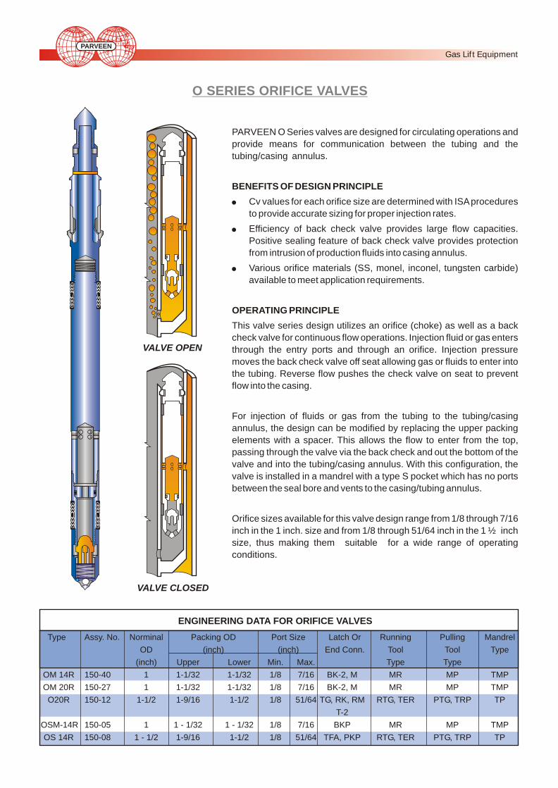
VALVE OPEN
VALVE CLOSED
O SERIES ORIFICE VALVES
PARVEEN O Series valves are designed for circulating operations and
provide means for communication between the tubing and the
tubing/casing annulus.
BENEFITS OF DESIGN PRINCIPLE
! Cv values for each orifice size are determined with ISA procedures
to provide accurate sizing for proper injection rates.
! Efficiency of back check valve provides large flow capacities.
Positive sealing feature of back check valve provides protection
from intrusion of production fluids into casing annulus.
! Various orifice materials (SS, monel, inconel, tungsten carbide)
available to meet application requirements.
OPERATING PRINCIPLE
This valve series design utilizes an orifice (choke) as well as a back
check valve for continuous flow operations. Injection fluid or gas enters
through the entry ports and through an orifice. Injection pressure
moves the back check valve off seat allowing gas or fluids to enter into
the tubing. Reverse flow pushes the check valve on seat to prevent
flow into the casing.
For injection of fluids or gas from the tubing to the tubing/casing
annulus, the design can be modified by replacing the upper packing
elements with a spacer. This allows the flow to enter from the top,
passing through the valve via the back check and out the bottom of the
valve and into the tubing/casing annulus. With this configuration, the
valve is installed in a mandrel with a type S pocket which has no ports
between the seal bore and vents to the casing/tubing annulus.
Orifice sizes available for this valve design range from 1/8 through 7/16
inch in the 1 inch. size and from 1/8 through 51/64 inch in the 1 ½ inch
size, thus making them suitable for a wide range of operating
conditions.
Type Assy. No. Norminal Packing OD Port Size Latch Or Running Pulling Mandrel
OD (inch) (inch) End Conn. Tool Tool Type
(inch) Upper Lower Min. Max. Type Type
OM 14R 150-40 1 1-1/32 1-1/32 1/8 7/16 BK-2, M MR MP TMP
OM 20R 150-27 1 1-1/32 1-1/32 1/8 7/16 BK-2, M MR MP TMP
O20R 150-12 1-1/2 1-9/16 1-1/2 1/8 51/64 TG, RK, RM RTG, TER PTG, TRP TP
T-2
OSM-14R 150-05 1 1 - 1/32 1 - 1/32 1/8 7/16 BKP MR MP TMP
OS 14R 150-08 1 - 1/2 1-9/16 1-1/2 1/8 51/64 TFA, PKP RTG, TER PTG, TRP TP
ENGINEERING DATA FOR ORIFICE VALVES
PARVEEN
Gas Lif t Equipment

MR-01
Running ToolNominal O.D. (Inch)
Assly Number.
PKO
Type Latch Mandrel Series.
PKO GAS LIFT ORIFICE VALVE
DESCRIPTION
The PARVEEN (Model PKO) retrievable single point injection gas lift orifice valve
s are used for continuous tubing flow gas lift installations. It is used to control the
flow of gas between the casing annulus and t he tubing at valve depth. The valve
has a check dart controlled by a spring which does not allow the back flow of gas
or well fluids. If the injection gas pressure in casing & tubing annulus at valve
depth falls below the fluid tubing pressure, the fluid from tubing will try to flow back
through the valve. Reverse flow through the valve is prevented by a check dart in
the valve body. T he check dart is closed by pressure from the tubing and will not
allow passage of fluid until casing pressure is greater or equal than tubing
pressure. T his valve is available from 1/8" to 3/8" port sizes in 1/16" increments.
The valve can be installed in Parveen TM series Side Pocket Mandrel & have an
integral bottom latch which locks the valve in the side pocket mandrel. After
locating the valve in the side pocket mandrel, downward jarring is required which
causes the collet dogs of the latch to engage the lock in the recess provided at
the bottom of the Side Pocket . Upward jarring is required to pull the valve. Upward
jarring shears the brass shear pin securing the shear ring to the latch body. During
upward pulling of the valve in the side pocket the shoulder on the latch body
moves out from behind the collet dogs.T he collet fingers are deflected inward and
disengage from the locking recess of the mandrel pocket. Then the valve is
removed from the well.
Injection gas enters thru the external ports of the orifice valve from annulus
between casing & tubing. 2 sets of packing located at the top & bottom of external
ports on the valve seals across the ports in side pocket mandrel. The injection gas
travels through the choke, past the reverse flow check valve and finally into the
production conduit.
ENGINEERING DATA FOR PKO GAS LIFT ORIFICE VALVES.
Pulling Tool
Type Assly No. Type
130-30 XX-XXX -01
1 IntegralBottom
10336-01 MP 11361 TMP, KBM,KBMG, KBG.
Assly No.
PKO GAS LIFTORIFICE VALVE
PARVEEN
Gas Lif t Equipment
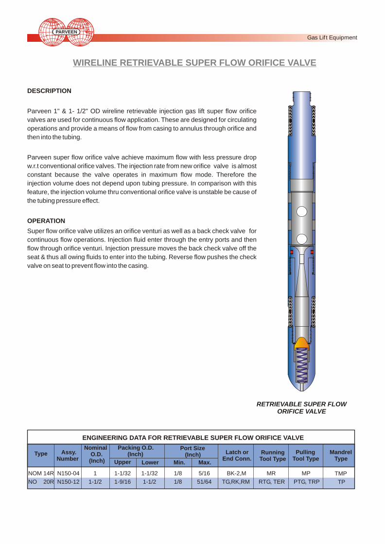
WIRELINE RETRIEVABLE SUPER FLOW ORIFICE VALVE
DESCRIPTION
Parveen 1" & 1- 1/2" OD wireline retrievable injection gas lift super flow orifice
valves are used for continuous flow application. These are designed for circulating
operations and provide a means of flow from casing to annulus through orifice and
then into the tubing.
Parveen super flow orifice valve achieve maximum flow with less pressure drop
w.r.t conventional orifice valves. The injection rate from new orifice valve is almost
constant because the valve operates in maximum flow mode. Therefore the
injection volume does not depend upon tubing pressure. In comparison with this
feature, the injection volume thru conventional orifice valve is unstable be cause of
the tubing pressure effect.
OPERATION
Super flow orifice valve utilizes an orifice venturi as well as a back check valve for
continuous flow operations. Injection fluid enter through the entry ports and then
flow through orifice venturi. Injection pressure moves the back check valve off the
seat & thus all owing fluids to enter into the tubing. Reverse flow pushes the check
valve on seat to prevent flow into the casing.
Packing O.D. (Inch)
Upper Lower Max.Min.
Port Size (Inch) Latch or
End Conn. Running Tool Type
Pulling Tool Type
Mandrel Type
TMP
TP
MP
PTG, TRP
MR
RTG, TER
BK-2,M
TG,RK,RM
5/16
51/64
1/8
1/8
1-1/32
1-1/2
1-1/32
1-9/16
ENGINEERING DATA FOR RETRIEVABLE SUPER FLOW ORIFICE VALVE
Type Assy.Number
Nominal O.D. (Inch)
1
1-1/2
N150-04
N150-12
NOM 14R
NO 20R
RETRIEVABLE SUPER FLOW ORIFICE VALVE
PARVEEN
Gas Lif t Equipment

0 5 10 15 20 25 30 350
2000
4000
6000
8000
10000
12000
Flow Performance (NOM14-R, Port12/64”) 2Upstream Pressure - 30 Kg/cm
Ga
s F
low
ra
te (
SC
MD
)
0 5 10 15 20 25 30 350
2000
4000
6000
8000
10000
12000
Ga
s F
low
ra
te (
SC
MD
)
40
Flow Performance (NOM14-R, Port12/64”) 2Upstream Pressure - 35 Kg/cm
FLOW CHARACTERISTICS OF SUPER FLOW ORIFICE VALVE
ANALYSIS OF RESULTS
Parveen has Successfully developed after conducting extensive in house research Super Flow Orifice Valve which
is a one step ahead of Conventional Orifice Valve available in the market. It’s performance is dynamically tested by
Institute of Oil & Gas Production Technology, ONGCL, Panvel, Mumbai, India.
Flow Performance Curve of NOM - 14R Orifice Valve (Port - 12/64”) against different Upstream Pressures i.e. 2 230 Kg/cm & 35 Kg/cm are depicted below and comparison with Conventional Square Edge Orifice Valve are also
shown below.
The Critical Flow rate was achieved at
approx 0.878-0.879 pressure ratio of Down
Stream Pressure to Upstream Pressure i.e.
at a pressure differential of 12% compared to
almost 50% in case of a Standard Orifice in
Conventional Orifice Valve.
The Actual Critical Flow rates obtained
through the testing were approximately 20%
higher than the calculated theoretical flow
rates.
1)
2)
PARVEEN
Gas Lif t Equipment

PDO-5 GAS LIFT ORIFICE VALVE
DESCRIPTION
The PARVEEN (Model PDO-5) 1.1/2" O.D. retrievable single point injection gas lift
orifice valves are used for continuous tubing flow gas lift installations. It is used to
control the flow of gas between the casing / tubing annulus and the tubing at valve
depth. The valve has a check dart controlled by a spring which does not allow the
back flow of gas or well fluids.
An integral floating choke controls the flow of gas through this valve (which is
open normally) into the production conduit. This valve is available from 3/16" to
3/4" port sizes in 1/16" increments.
This valve design utilizes an orifice (choke) as well as a back check valve for
continuous flow operations. Injection fluid or gas enters through the entry ports
and through an orifice. Injection pressure moves the back check valve off seat
allowing the gas or fluids to enter into the tubing. Reverse flow pushes the check
valve on seat to prevent flow into the casing.
RTGTER
Running ToolNominal O.D. (Inch)
Assly Number.
PDO-05
Type Latch Mandrel Series.
Pulling Tool
Type Assly No. Type
150-30 XX-XXX -01
1.1/2 R,RA,RK.
1692711730
PTGTRP
1704811390
TP,MMA,MMG.
Assly No.
PDO-5 GAS LIFTORIFICE VALVE
ENGINEERING DATA FOR PDO-5 GAS LIFT ORIFICE VALVE.
PARVEEN
Gas Lif t Equipment

DIFFERENTIAL VALVE
DIFFERENTIAL VALVE
This valve is used as the bleed valve in chamber lift installation for
bleeding the tail chamber gas from the chamber, which allows for the
formation to refill the chamber. The valve is normally open and closes
when differential pressure closes against the calibrated spring.
FUNCTION
When chamber is empty, there is a reduction in chamber pressure. Due
to this differential, valve opens which allows the passage of gas
from the top of chamber and prevents trapping of gas in top of the
chamber. When gas pressure on the top of the liquid in the chamber
increases, the spring compresses & valve closes.
Packing O.D. (Inch)
Upper Lower
Latch orEnd Conn.
Running Tool Type
Pulling Tool Type
Mandrel Type
Series -12
TMP
-
MP
-
MR
-
BK-2, M
1-1/32
1-1/32
1-1/32
1-1/32
ENGINEERING DATA FOR DIFFERENTIAL VALVE
Type Assy. Number
Nominal O.D. (Inch)
1
1
160-1024-320-00
160-1024-320-01
PDV
PDV-R
PDV PDV-R
PARVEEN
Gas Lif t Equipment

DUMMY AND EQUALIZING VALVES
D Series Valves are installed in side pocket mandrels by wireline to block the mandrel's
injection gas ports. Dummies can be run prior to or after completion for testing tubing,
packers and other equipment. In new installations, dummies can be retained in the
mandrels until gas lift valves are required to maintain production. Then, dummies are
pulled and gas lift valves installed by wireline. Also during the life of the well, gas lift
valves installed above the fluid level can be replaced with dummies to block off injection
gas. They are available in 1 and 1 ½ inch sizes.
ED Series Equalizing Valves with integral latches are designed to equalize tubing and
casing pressure and or to circulate prior to pulling the valve. They are also available in
both 1 and 1 ½ inch sizes.
To equalize pressure, a pulling tool pushes the inner core downward, shearing a pin and
allowing circulation or equalization. When the core moves down, the pulling tool collets
latch over the fish neck and the valve is pulled in the usual manner. This tool is designed
so that both equalizing and pulling operations can be performed in one wireline run. It is
also possible to leave the valve in the side pocket mandrel for continued circulation. This
is accomplished by shearing down on the inner core with a special tool. The valve may
be pulled out at a later date with a standard pulling tool.
STANDARD SERIES MODELS
D-14R: 1 ½ inch wireline-retrievable dummy valve for TG or T Mandrels with TG, RK, RM
and T2 Latches.
DM-14R: 1 inch wireline-retrievable dummy valve for TM Mandrels with BK-2 and M
Latches.
DT-14R: 1½ inch wireline-retrievable, high-temperature dummy valve for TG or TP
Mandrels with TG, RK, RM and T2 Latches.
DTM-14R: 1inch wireline-retrievable, high-temperature dummy valve for TMP Mandrels
with BK-2 and M Latches.
! ED-30R: 1½ inch wireline-retrievable equalizing dummy valve for TG or TP
Mandrels with an integral Latch.
! EDM-30R: 1 inch wireline-retrievable equalizing dummy valve for TMP Mandrels
with an integral BK-2 Latch.
! Both of these valves may be equalized and pulled with one wireline run.1½ inch Dummy
Valve
Type Assy. No. Nominal Packing OD Latch Or Running Pulling Mandrel
OD (inch) End Conn. Tool Tool Type
(inch) Upper Lower Type Type
D 14R 170-03 1-1/2 1-9/16 1-1/2 TG, RK, RM RTG, PTG, TP
T2 TER TRP
DM 14R 170-01 1 1-1/32 1-1/32 BK-2, M MR MP TMP
DT 14R 170 1-1/2 1-9/16 1-1/2 TG, RK, RM RTG, M, PTG, TP
T-2 TER TRP
DTM 14R 170-02 1 1-1/32 1-1/32 BK-2, M MR MP TMP
ED 30 R 170-XXX 1-1/2 1-9/16 1-1/2 TGP, RKP, RTG, PTG, TP
TFA TER TRP
EDM 30 R 170-08 1 1-1/32 1-1/32 BKP MR MP TMP
ENGINEERING DATA FOR D & ED SERIES DUMMY VALVES
PARVEEN
Gas Lif t Equipment

PDK-1 WIRELINE RETRIEVABLE DUMMY VALVE
FUNCTION
The PARVEEN wireline Retrievable Dummy Valves (PDK -1) have 2 sets of
packing which fit in the seal bore of side pocket mandrel and isolate the casing
ports between tubing and casing annulus. In other words the valves are used to prevent
communication between the tubing and the casing.
APPLICATION
These Valve s are used in side pocket mandrel to provide a positive seal between
casing - tubing annulus and to protect the mandrel seal bore until they are
retrieved by standard wireline methods. When installed, the PDK-1 Dummy Valves
eliminates unintentional placement of the other tools or debris in the mandrel
pocket.
Packing O.D. (Inch)
Upper Lower
Latch orEnd Conn.
Running Tool Type
Pulling Tool Type
Mandrel Type
TMP MPGA - 2IntegralBottom
1-1/321-1/32
Nominal O.D. (Inch)
1
Assy.Number
170-09
Type
PDK - 1
ENGINEERING DATA FOR WIRELINE RETRIEVABLE (PDK-1) DUMMY VALVES.
PDK-1
PARVEEN
Gas Lif t Equipment

DESCRIPTION
Parveen wireline retrievable production pressure operated GLV' s are used for continuous flow gas lift production. A nitrogen charged multiply monel bellow provides the force necessary to maintain valve in a normally closed position.T his valve contain integral reverse flow check valve.
Port sizes available are 3/16", 1/4" & 5/16”
OPERATION
Production fluid enters the valve and acts on the effective bellow area.T he production pressure necessary to compress the bellow is controlled by precharged nitrogen pressure. When production pressure overcomes the precharged nitrogen pressure in the bellow, the bellow is compressed and lifts the stem tip off the seat. Injection gas flows through the seat, past the reverse flow check valve and into the production conduit.
RETRIEVABLE PRODUCTION - PRESSURE OPERATED GAS LIFT VALVES
RTG,TER
Running ToolNominal O.D. (Inch)
Assly Number.
PR 5
Type Latch Mandrel Series.
ENGINEERING DATA FOR RETRIEVABLE PRODUCTION-PRESSURE VALVE .
Pulling Tool
Type Assly No. Type
160-40 XX-XXX -01
1.1/2 R,RA,RK.
1692711730
PTG,TRP
1704811390
MM,MMA,MMG.
Assly No.
PR-5GAS LIFT VALVE
PARVEEN
Gas Lif t Equipment

DESCRIPTION
PARVEEN 1" OD PBK-2 is retrievable, production pressure operated Gas Lift Valves which is
used in continuous flow gas lift installations. The PBK-2 valve is bellow actuated with nitrogen
gas which normally keep the valve in closed position. This valve is having integral reverse flow
check valve crossover seat & floating seat. Port sizes available are 1/8", 3/16" and 1/4".
Optional choke is also available with this type of valve which can be easily fitted to the external
surface of the valve and can be easily removed. The valve can be installed in Parveen TMP
series Side Pocket Mandrel & have an integral bottom latch which locks the valve in the side
pocket mandrel.A fter locating the valve in the side pocket, down ward jarring is required which
causes the collet dogs of the latch to engage the locking recess provided at the bottom of the side
pocket. Upward jarring is required to pull the valve. Upward jarring shears the brass shear pin
securing the shear ring to the latch body. During upward pulling of the valve in the side pocket,
the shoulder on the latch body moves out from behind the collet dogs. The collet fingers are
deflected inward and disengage from the locking recess of the mandrel pocket. Then the valve
will be free in the pocket of the mandrel and can be removed.
Production pressure enters through the valve nose and passed upward through cross over
seat. The production pressure acts on the effective bellow area. As production pressure
overcomes the pre-charged nitrogen pressure in the bellows, the bellow compressed and lifts
the stem off the seat. The injection gas then flows through the seat, past the reverse flow check
valve and into the production conduit. If the injection gas pressure in the casing & tubing
annulus at valve depth falls bellow the valve set pressure, the valve is closed. Reverse flow
through the valve is prevented by a check dart in the valve body.
MR-01
Running ToolNominal O.D. (Inch)
Assly Number.
PBK-2
Type Latch Mandrel Series.
ENGINEERING DATA FOR RETRIEVABLE PRODUCTION-PRESSURE OPERATED VALVES.
Pulling Tool
Type Assly No. Type
160-40 XX-XXX -01
1 IntegralBottom
10336-01 MP 11361 TMP, KBM,KBMG, KBG.
Assly No.
PBK-2GAS LIFT VALVE
RETRIEVABLE PRODUCTION - PRESSURE OPERATED GAS LIFT VALVES
PARVEEN
Gas Lif t Equipment
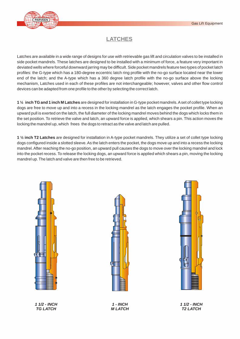
1 1/2 - INCHTG LATCH
1 - INCH M LATCH
1 1/2 - INCH T2 LATCH
LATCHES
Latches are available in a wide range of designs for use with retrievable gas lift and circulation valves to be installed in
side pocket mandrels. These latches are designed to be installed with a minimum of force, a feature very important in
deviated wells where forceful downward jarring may be difficult. Side pocket mandrels feature two types of pocket latch
profiles: the G-type which has a 180-degree eccentric latch ring profile with the no-go surface located near the lower
end of the latch; and the A-type which has a 360 degree latch profile with the no-go surface above the locking
mechanism, Latches used in each of these profiles are not interchangeable; however, valves and other flow control
devices can be adapted from one profile to the other by selecting the correct latch.
1 ½ inch TG and 1 inch M Latches are designed for installation in G-type pocket mandrels. A set of collet type locking
dogs are free to move up and into a recess in the locking mandrel as the latch engages the pocket profile. When an
upward pull is exerted on the latch, the full diameter of the locking mandrel moves behind the dogs which locks them in
the set position. To retrieve the valve and latch, an upward force is applied, which shears a pin. This action moves the
locking the mandrel up, which frees the dogs to retract as the valve and latch are pulled.
1 ½ inch T2 Latches are designed for installation in A-type pocket mandrels. They utilize a set of collet type locking
dogs configured inside a slotted sleeve. As the latch enters the pocket, the dogs move up and into a recess the locking
mandrel. After reaching the no-go position, an upward pull causes the dogs to move over the locking mandrel and lock
into the pocket recess. To release the locking dogs, an upward force is applied which shears a pin, moving the locking
mandrel up. The latch and valve are then free to be retrieved.
PARVEEN
Gas Lif t Equipment
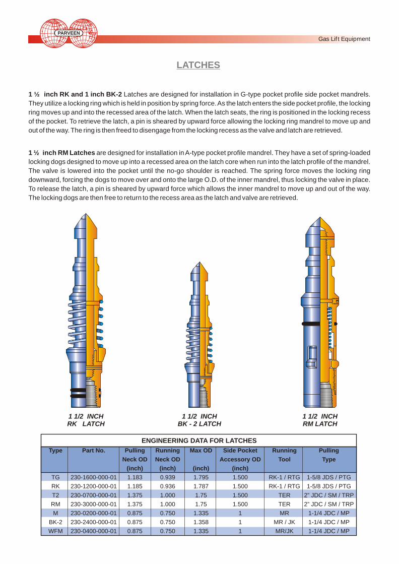
LATCHES
1 ½ inch RK and 1 inch BK-2 Latches are designed for installation in G-type pocket profile side pocket mandrels.
They utilize a locking ring which is held in position by spring force. As the latch enters the side pocket profile, the locking
ring moves up and into the recessed area of the latch. When the latch seats, the ring is positioned in the locking recess
of the pocket. To retrieve the latch, a pin is sheared by upward force allowing the locking ring mandrel to move up and
out of the way. The ring is then freed to disengage from the locking recess as the valve and latch are retrieved.
1 ½ inch RM Latches are designed for installation in A-type pocket profile mandrel. They have a set of spring-loaded
locking dogs designed to move up into a recessed area on the latch core when run into the latch profile of the mandrel.
The valve is lowered into the pocket until the no-go shoulder is reached. The spring force moves the locking ring
downward, forcing the dogs to move over and onto the large O.D. of the inner mandrel, thus locking the valve in place.
To release the latch, a pin is sheared by upward force which allows the inner mandrel to move up and out of the way.
The locking dogs are then free to return to the recess area as the latch and valve are retrieved.
1 1/2 INCHRK LATCH
1 1/2 INCHBK - 2 LATCH
1 1/2 INCHRM LATCH
Type Part No. Pulling Running Max OD Side Pocket Running Pulling
Neck OD Neck OD Accessory OD Tool Type
(inch) (inch) (inch) (inch)
TG 230-1600-000-01 1.183 0.939 1.795 1.500 RK-1 / RTG 1-5/8 JDS / PTG
RK 230-1200-000-01 1.185 0.936 1.787 1.500 RK-1 / RTG 1-5/8 JDS / PTG
T2 230-0700-000-01 1.375 1.000 1.75 1.500 TER 2” JDC / SM / TRP
RM 230-3000-000-01 1.375 1.000 1.75 1.500 TER 2” JDC / SM / TRP
M 230-0200-000-01 0.875 0.750 1.335 1 MR 1-1/4 JDC / MP
BK-2 230-2400-000-01 0.875 0.750 1.358 1 MR / JK 1-1/4 JDC / MP
WFM 230-0400-000-01 0.875 0.750 1.335 1 MR/JK 1-1/4 JDC / MP
ENGINEERING DATA FOR LATCHES
PARVEEN
Gas Lif t Equipment
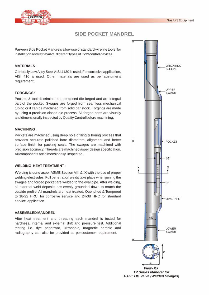
Parveen Side Pocket Mandrels allow use of standard wireline tools for
installation and retrieval of different types of flow control devices.
MATERIALS :
Generally Low Alloy Steel AISI 4130 is used. For corrosive application,
AISI 410 is used. Other materials are used as per customer’s
requirement .
FORGINGS :
Pockets & tool discriminators are closed die forged and are integral
part of the pocket. Swages are forged from seamless mechanical
tubing or it can be machined from solid bar stock. Forgings are made
by using a precision closed die process. All forged parts are visually
and dimensionally inspected by Quality Control before machining.
MACHINING :
Pockets are machined using deep hole drilling & boring process that
provides accurate polished bore diameters, alignment and better
surface finish for packing seals. The swages are machined with
precision accuracy. Threads are machined asper design specification.
All components are dimensionally inspected.
WELDING HEAT TREATMENT :
Welding is done asper ASME Section VIII & IX with the use of proper
welding electrodes. Full penetration welds take place when joining the
swages and forged pocket are welded to the oval pipe. After welding,
all external weld deposits are evenly grounded down to match the
outside profile. All mandrels are heat treated, Quenched & Tempered
to 18-22 HRC, for corrosive service and 24-38 HRC for standard
service application.
ASSEMBLED MANDREL :
After heat treatment and threading each mandrel is tested for
hardness, internal and external drift and pressure test. Additional
testing i.e. dye penetrant, ultrasonic, magnetic particle and
radiography can also be provided as per customer requirement.
SIDE POCKET MANDREL
TP Series Mandrel for 1-1/2” OD Valve (Welded Swages)
View- XX
B
C
ORIENTING SLEEVE
UPPER SWAGE
X X
A
OVAL PIPE
LOWER SWAGE
PARVEEN
Gas Lif t Equipment
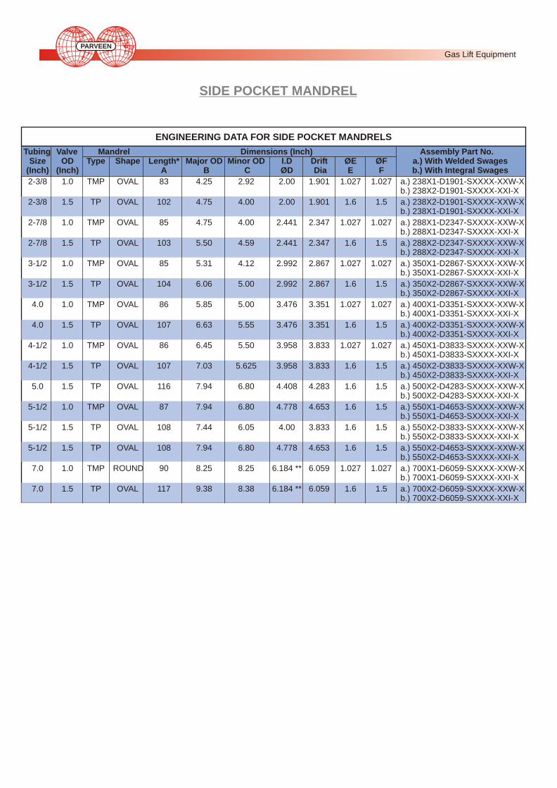
Tubing Valve Mandrel Dimensions (Inch) Assembly Part No.Size OD Type Shape Length* Major OD Minor OD I.D Drift ØE ØF a.) With Welded Swages
(Inch) (Inch) A B C ØD Dia E F b.) With Integral Swages
2-3/8 1.0 TMP OVAL 83 4.25 2.92 2.00 1.901 1.027 1.027 a.) 238X1-D1901-SXXXX-XXW-Xb.) 238X2-D1901-SXXXX-XXI-X
2-3/8 1.5 TP OVAL 102 4.75 4.00 2.00 1.901 1.6 1.5 a.) 238X2-D1901-SXXXX-XXW-Xb.) 238X1-D1901-SXXXX-XXI-X
2-7/8 1.0 TMP OVAL 85 4.75 4.00 2.441 2.347 1.027 1.027 a.) 288X1-D2347-SXXXX-XXW-Xb.) 288X1-D2347-SXXXX-XXI-X
2-7/8 1.5 TP OVAL 103 5.50 4.59 2.441 2.347 1.6 1.5 a.) 288X2-D2347-SXXXX-XXW-Xb.) 288X2-D2347-SXXXX-XXI-X
3-1/2 1.0 TMP OVAL 85 5.31 4.12 2.992 2.867 1.027 1.027 a.) 350X1-D2867-SXXXX-XXW-Xb.) 350X1-D2867-SXXXX-XXI-X
3-1/2 1.5 TP OVAL 104 6.06 5.00 2.992 2.867 1.6 1.5 a.) 350X2-D2867-SXXXX-XXW-Xb.) 350X2-D2867-SXXXX-XXI-X
4.0 1.0 TMP OVAL 86 5.85 5.00 3.476 3.351 1.027 1.027 a.) 400X1-D3351-SXXXX-XXW-Xb.) 400X1-D3351-SXXXX-XXI-X
4.0 1.5 TP OVAL 107 6.63 5.55 3.476 3.351 1.6 1.5 a.) 400X2-D3351-SXXXX-XXW-Xb.) 400X2-D3351-SXXXX-XXI-X
4-1/2 1.0 TMP OVAL 86 6.45 5.50 3.958 3.833 1.027 1.027 a.) 450X1-D3833-SXXXX-XXW-Xb.) 450X1-D3833-SXXXX-XXI-X
4-1/2 1.5 TP OVAL 107 7.03 5.625 3.958 3.833 1.6 1.5 a.) 450X2-D3833-SXXXX-XXW-Xb.) 450X2-D3833-SXXXX-XXI-X
5.0 1.5 TP OVAL 116 7.94 6.80 4.408 4.283 1.6 1.5 a.) 500X2-D4283-SXXXX-XXW-Xb.) 500X2-D4283-SXXXX-XXI-X
5-1/2 1.0 TMP OVAL 87 7.94 6.80 4.778 4.653 1.6 1.5 a.) 550X1-D4653-SXXXX-XXW-Xb.) 550X1-D4653-SXXXX-XXI-X
5-1/2 1.5 TP OVAL 108 7.44 6.05 4.00 3.833 1.6 1.5 a.) 550X2-D3833-SXXXX-XXW-Xb.) 550X2-D3833-SXXXX-XXI-X
5-1/2 1.5 TP OVAL 108 7.94 6.80 4.778 4.653 1.6 1.5 a.) 550X2-D4653-SXXXX-XXW-Xb.) 550X2-D4653-SXXXX-XXI-X
7.0 1.0 TMP ROUND 90 8.25 8.25 6.184 ** 6.059 1.027 1.027 a.) 700X1-D6059-SXXXX-XXW-Xb.) 700X1-D6059-SXXXX-XXI-X
7.0 1.5 TP OVAL 117 9.38 8.38 6.184 ** 6.059 1.6 1.5 a.) 700X2-D6059-SXXXX-XXW-Xb.) 700X2-D6059-SXXXX-XXI-X
ENGINEERING DATA FOR SIDE POCKET MANDRELS
SIDE POCKET MANDREL
Gas Lift Equipment PARVEEN
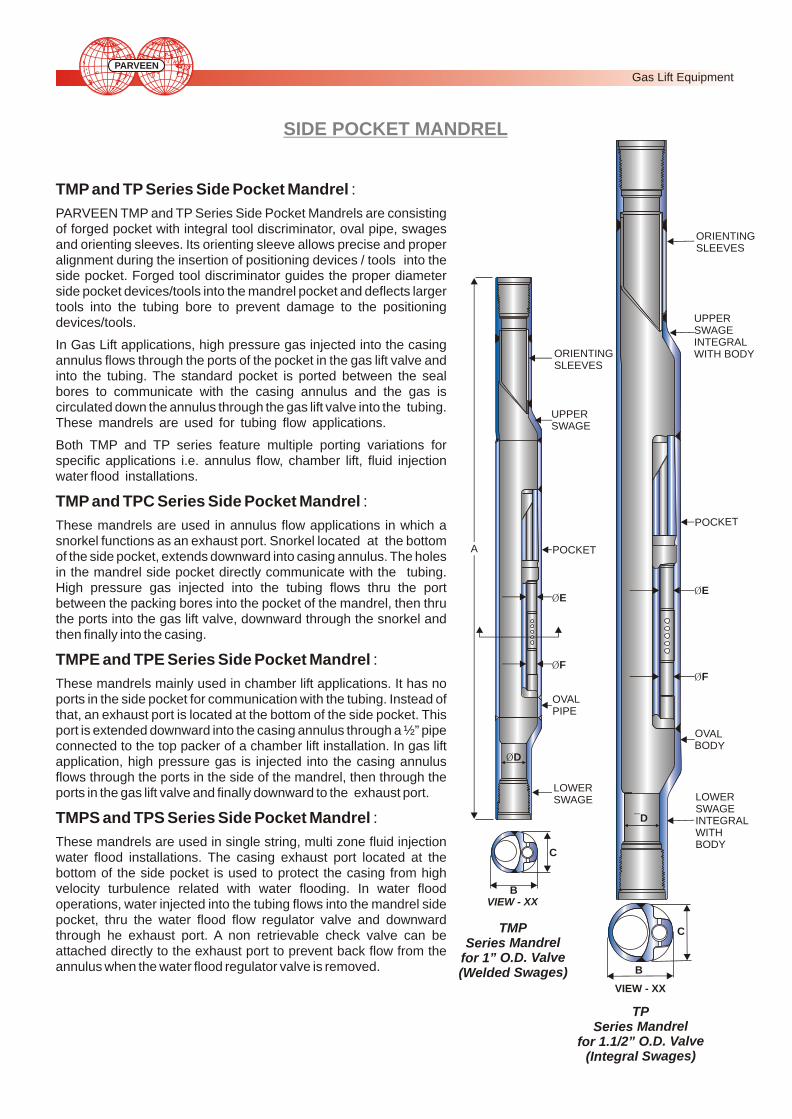
TMP and TP Series Side Pocket Mandrel :
PARVEEN TMP and TP Series Side Pocket Mandrels are consisting of forged pocket with integral tool discriminator, oval pipe, swages and orienting sleeves. Its orienting sleeve allows precise and proper alignment during the insertion of positioning devices / tools into the side pocket. Forged tool discriminator guides the proper diameter side pocket devices/tools into the mandrel pocket and deflects larger tools into the tubing bore to prevent damage to the positioning devices/tools.
In Gas Lift applications, high pressure gas injected into the casing annulus flows through the ports of the pocket in the gas lift valve and into the tubing. The standard pocket is ported between the seal bores to communicate with the casing annulus and the gas is circulated down the annulus through the gas lift valve into the tubing. These mandrels are used for tubing flow applications.
Both TMP and TP series feature multiple porting variations for specific applications i.e. annulus flow, chamber lift, fluid injection water flood installations.
TMP and TPC Series Side Pocket Mandrel :
These mandrels are used in annulus flow applications in which a snorkel functions as an exhaust port. Snorkel located at the bottom of the side pocket, extends downward into casing annulus. The holes in the mandrel side pocket directly communicate with the tubing. High pressure gas injected into the tubing flows thru the port between the packing bores into the pocket of the mandrel, then thru the ports into the gas lift valve, downward through the snorkel and then finally into the casing.
TMPE and TPE Series Side Pocket Mandrel :
These mandrels mainly used in chamber lift applications. It has no ports in the side pocket for communication with the tubing. Instead of that, an exhaust port is located at the bottom of the side pocket. This port is extended downward into the casing annulus through a ½” pipe connected to the top packer of a chamber lift installation. In gas lift application, high pressure gas is injected into the casing annulus flows through the ports in the side of the mandrel, then through the ports in the gas lift valve and finally downward to the exhaust port.
TMPS and TPS Series Side Pocket Mandrel :
These mandrels are used in single string, multi zone fluid injection water flood installations. The casing exhaust port located at the bottom of the side pocket is used to protect the casing from high velocity turbulence related with water flooding. In water flood operations, water injected into the tubing flows into the mandrel side pocket, thru the water flood flow regulator valve and downward through he exhaust port. A non retrievable check valve can be attached directly to the exhaust port to prevent back flow from the annulus when the water flood regulator valve is removed.
PPER USWAGE
T RAL IN EGH YWIT BOD
ORIENTING SLEEVES
OVAL BO YD
LOWER S GWA EINTEGRAL WITH B DYO
VIEW - XX
I W V E - XXB
C
B
C
SIDE POCKET MANDREL
¯E
¯F
¯D
MPTSeries Mandrel
for 1” O D Valve . .Welded S ges)( wa
TPe M ndS ries a rel
f / . lor 1.1 2” O D. Va veInt g w s( e ral S age )
L OVAPI EP
L WO ERSWAGE
U PER PSWAGE
OCKEP T
NT NGORIE ISLEEVES
¯F
¯E
¯D
A
Gas Lift Equipment PARVEEN

2-3/8 1.0 TMP 75.0 (34) 0.47 8000 7000 6000 5500
2-3/8 1.5 TP 130 (59) 0.88 7500 6500 6000 5000
2-7/8 1.0 TMP 121.25 (55) 0.73 8000 7000 6000 5500
2-7/8 1.5 TP 180.77 (82) 1.18 7500 6500 6000 5000
3-1/2 1.0 TMP 150.00 (68) 0.84 8000 6500 6000 5000
3-1/2 1.5 TP 209.4 (95) 1.43 8000 6500 7000 5500
4.0 1.0 TMP 205.0 (92) 1.14 8000 6500 7000 5500
4.0 1.5 TP 236.0 (107) 1.78 8000 6500 7000 5500
4-1/2 1.0 TMP 216.0 (98) 1.38 7500 6000 6000 5000
4-1/2 1.5 TP 242.5 (110) 1.92 7500 6000 6000 5000
5.0 1.5 TP 310.8 (141) 2.84 8500 7000 6500 5500
5-1/2 1.0 TMP 262.3 (119) 2.13 7500 6000 6000 5000
5-1/2 1.5 TP 291.0 (132) 2.20 7500 6000 6000 5000
5-1/2 1.5 TP 297.6 (135) 2.64 8500 7000 6500 5500
7.0 1.0 TMP 405.6 (184) 2.8 7000 5500 5000 4500
7.0 1.5 TP 452.0 (205) 4.17 7000 5500 5000 4500
Tubing Size
(Inch)
ValveOD
(Inch)
Mandrel Type
Weight Lbs - F*(Kg - F)
Volume(Cubic
Ft.) Internal External
Standard Services
Internal External
Corrosive Services
Test Pressure (PSI)*
PRESSURE RATING FOR SIDE POCKET MANDRELS
NOTES:
* Test Pressures given are for mandrels made of AISI-4130 materials heat treated for standard or corrosive
environments. Test Pressures may be reduced due to end connection limitations.
** Weight and Length may vary depending upon end connection etc.
*** For 7” TMP & TP Series other drift sizes can also be provided upon request.
SIDE POCKET MANDREL
Gas Lift Equipment PARVEEN
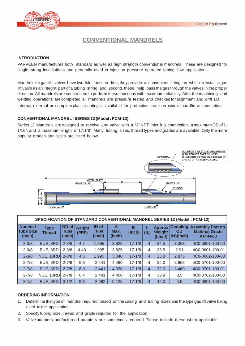
CONVENTIONAL MANDRELS
INTRODUCTION
PARVEEN manufactures both standard as well as high strength conventional mandrels. These are designed for
single - string installations and generally used in injection pressure operated tubing flow applications.
Mandrels for gas lift valves have two-fold function - first, they provide a convenient fitting on which to install a gas
lift valve as an integral part of a tubing string and second, these help pass the gas through the valves in the proper
direction. All mandrels are constructed to perform these functions with maximum reliability. After the machining and
welding operations are completed, all mandrels are pressure tested and checked for alignment and drift I.D.
Internal, external or complete plastic coating is available for protection from corrosion or paraffin accumulation.
CONVENTIONAL MANDREL - SERIES 12 (Model : PCM-12)
Series 12 Mandrels are designed to receive any valve with a ½" NPT inlet lug connection, a maximum OD of 1-
1/16", and a maximum length of 17.1/8”. Many tubing sizes, thread types and grades are available. Only the more
popular grades and sizes are listed below.
Type Thread
2-3/8 EUE, 8RD 2-3/8 4.7 1.995 3.920 17-1/8 4 24.5 3.063 4C0-0601-100-00
2-3/8 EUE, 8RD 2-3/8 4.43 1.995 3.825 17-1/8 4 23.5 2.91 4C0-0601-100-01
2-3/8 NUE, 10RD 2-3/8 4.6 1.995 3.840 17-1/8 4 23.8 2.875 4C0-0602-100-00
2-7/8 EUE, 8RD 2-7/8 6.5 2.441 4.490 17-1/8 4 34.0 3.668 4C0-0701-100-00
2-7/8 EUE, 8RD 2-7/8 6.0 2.441 4.330 17-1/8 4 32.0 3.460 4C0-0701-100-01
2-7/8 NUE, 10RD 2-7/8 6.4 2.441 4.400 17-1/8 4 33.9 3.5 4C0-0702-100-00
3-1/2 EUE, 8RD 3-1/2 9.3 2.992 5.125 17-1/8 4 42.0 4.5 4C0-0801-100-00
ORDERING INFORMATION
1. Determine the type of mandrel required based on the casing and tubing sizes and the type gas lift valve being
used to the application.
2. Specify tubing size, thread and grade required for the application.
3. Valve adapters and/or thread adapters are sometimes required. Please include these when applicable.
SPECIFICATION OF STANDARD CONVENTIONAL MANDREL SERIES 12 (Model : PCM-12)
MULTIPORT INLET LUG ADVANTAGE1) TO REDUCE ENERGY LOSS2) UNIFORM DIFFUSION & MIXING OF GAS INTO THE TUBING FLUID.
OPTIONAL
A
B INLET LUG
TUBING
TUBE O.D
GUARD LUG
METAL PLATE
COUPLING
Nominal Tube Size
(inch)
OD ofTube (inch)
ID ofTube (inch)
AMax. (inch)
B (inch)
L(ft.)
Weight(PPF)
ApproxWeight(Lbs-f)
CouplingOD
C(inch)
Assembly Part no.Material Grade
API-N-80
TU
BE
I.D
L
¯C
Gas Lift Equipment PARVEEN

CONVENTIONAL MANDRELS
CONVENTIONAL MANDREL - SERIES 12 (MODEL : PCM-12S)
Series 12 Mandrels are designed to receive any valve with a ½" NPT inlet lug connection, a maximum OD of 1-
1/16", and a maximum length of 17.1/8”. Many tubing sizes, thread types and grades are available. Only the more
popular grades and sizes are listed below. These Mandrels use shroud instead of Grand Lug & Metal Plate.
SPECIFICATION OF STANDARD CONVENTIONAL MANDREL SERIES 12 (MODEL : PCM-12S)
CONVENTIONAL MANDRELS - SERIES 15 (MODEL : PCM-15)
Series 15 Conventional MANDRELS are designed to receive any valve with a ½" NPT inlet lug connection, a maximum
OD of 1- ½" and a maximum length of 29". Many tubing sizes, thread types, and grades are available. Only the more
popular grades and sizes are listed below.
SPECIFICATIONS OF STANDARD CONVENTIONAL MANDREL SERIES 15 (MODEL : PCM-15)
NOTE:
Using 2-3/8” EUE,8RD tubing inside 4-1/2” casing. The mandrel contains a shroud to provide valve protection.
Type Thread
2-3/8 EUE, 8RD 2-3/8 5.45 1.995 3.920 17-1/8 4 27.5 3.063 4C0-1601-100-00
2-3/8 EUE, 8RD 2-3/8 5.18 1.995 3.825 17-1/8 4 26.5 2.91 4C0-1601-100-01
2-3/8 NUE, 10RD 2-3/8 5.35 1.995 3.840 17-1/8 4 26.8 2.875 4C0-1602-100-00
2-7/8 EUE, 8RD 2-7/8 7.25 2.441 4.490 17-1/8 4 37.0 3.668 4C0-1701-100-00
2-7/8 EUE, 8RD 2-7/8 6.75 2.441 4.330 17-1/8 4 35.0 3.460 4C0-1701-100-01
2-7/8 NUE, 10RD 2-7/8 7.15 2.441 4.400 17-1/8 4 36.9 3.5 4C0-1702-100-00
3-1/2 EUE, 8RD 3-1/2 10.05 2.992 5.125 17-1/8 4 45.0 4.5 4C0-1801-100-00
Nominal Tube Size
(inch)
OD ofTube (inch)
ID ofTube (inch)
AMax. (inch)
B (inch)
L(ft.)
Weight(PPF)
ApproxWeight(Lbs-f)
CouplingOD
C(inch)
Assembly Part no.Material Grade
API-N-80
Type Thread
2-3/8 EUE, 8RD 2-3/8 4.7 1.995 4.577 29 4 27 3.063 4C2-3601-100-00
2-3/8 EUE, 8RD 2-3/8 4.43 1.995 4.375 29 4 26 2.91 4C2-3601-100-01
2-3/8 NUE, 10RD 2-3/8 4.60 1.995 4.484 29 4 26.4 2.875 4C2-3602-100-00
2-7/8 EUE, 8RD 2-7/8 6.50 2.441 5.130 29 4 36.5 3.668 4C2-3701-100-00
2-7/8 NUE, 10RD 2-7/8 6.40 2.441 5.046 29 4 36.3 3.50 4C2-3702-100-00
3-1/2 EUE, 8RD 3-1/2 9.30 2.992 5.859 29 4 44.5 4.50 4C2-3801-100-00
3-1/2 NUE, 10RD 3-1/2 8.98 2.992 5.734 29 4 43.6 4.25 4C2-3802-100-00
Nominal Tube Size
(inch)
OD ofTube (inch)
ID ofTube (inch)
AMax. (inch)
B (inch)
L(ft.)
Weight(PPF)
ApproxWeight(Lbs-f)
CouplingOD
C(inch)
Assembly Part no.Material Grade
API-N-80
A
B
MULTIPORT INLET LUG ADVANTAGE1) TO REDUCE ENERGY LOSS2) UNIFORM DIFFUSION & MIXING OF GAS INTO THE TUBING FLUID.
OPTIONAL
TU
BE I.
D
COUPLING
SHROUD
TUBE OD
INLET LUG
TUBING
¯C
Gas Lift Equipment PARVEEN
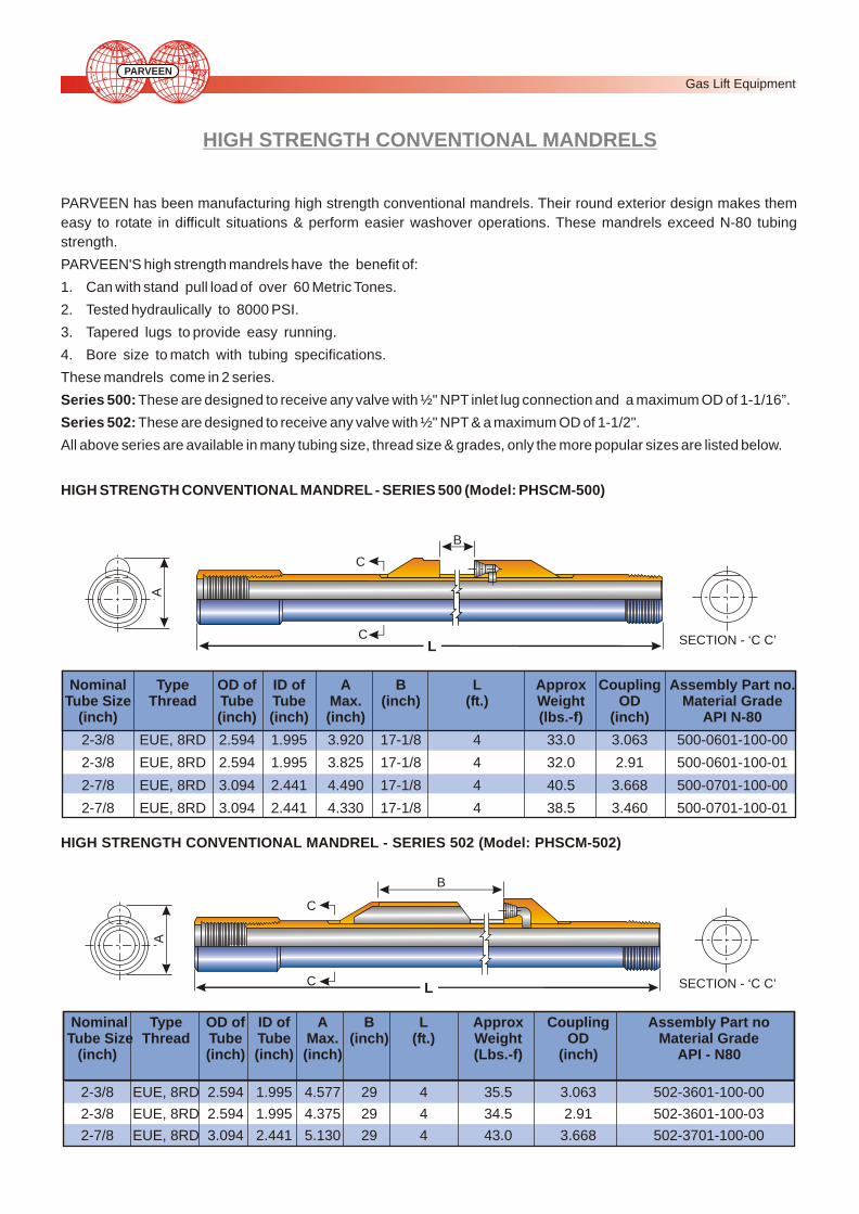
HIGH STRENGTH CONVENTIONAL MANDRELS
PARVEEN has been manufacturing high strength conventional mandrels. Their round exterior design makes them
easy to rotate in difficult situations & perform easier washover operations. These mandrels exceed N-80 tubing
strength.
PARVEEN'S high strength mandrels have the benefit of:
1. Can with stand pull load of over 60 Metric Tones.
2. Tested hydraulically to 8000 PSI.
3. Tapered lugs to provide easy running.
4. Bore size to match with tubing specifications.
These mandrels come in 2 series.
Series 500: These are designed to receive any valve with ½" NPT inlet lug connection and a maximum OD of 1-1/16”.
Series 502: These are designed to receive any valve with ½" NPT & a maximum OD of 1-1/2".
All above series are available in many tubing size, thread size & grades, only the more popular sizes are listed below.
HIGH STRENGTH CONVENTIONAL MANDREL - SERIES 500 (Model: PHSCM-500)
HIGH STRENGTH CONVENTIONAL MANDREL - SERIES 502 (Model: PHSCM-502)
Nominal Type OD of ID of A B L Approx Coupling Assembly Part noTube Size Thread Tube Tube Max. (inch) (ft.) Weight OD Material Grade
(inch) (inch) (inch) (inch) (Lbs.-f) (inch) API - N80
2-3/8 EUE, 8RD 2.594 1.995 4.577 29 4 35.5 3.063 502-3601-100-00
2-3/8 EUE, 8RD 2.594 1.995 4.375 29 4 34.5 2.91 502-3601-100-03
2-7/8 EUE, 8RD 3.094 2.441 5.130 29 4 43.0 3.668 502-3701-100-00
Nominal Type OD of ID of A B L Approx Coupling Assembly Part no. Tube Size Thread Tube Tube Max. (inch) (ft.) Weight OD Material Grade
(inch) (inch) (inch) (inch) (lbs.-f) (inch) API N-80
2-3/8 EUE, 8RD 2.594 1.995 3.920 17-1/8 4 33.0 3.063 500-0601-100-00
2-3/8 EUE, 8RD 2.594 1.995 3.825 17-1/8 4 32.0 2.91 500-0601-100-01
2-7/8 EUE, 8RD 3.094 2.441 4.490 17-1/8 4 40.5 3.668 500-0701-100-00
2-7/8 EUE, 8RD 3.094 2.441 4.330 17-1/8 4 38.5 3.460 500-0701-100-01
A
SECTION - ‘C C’
B
C
CL
B
C
C
A
SECTION - ‘C C’L
Gas Lift Equipment PARVEEN

RUNNING, PULLING TOOLS
Running Tools
PARVEEN Manufactures Wireline Running Tools used to install latches and valves, MR, RTG and TER running tools
are used to install appropriate latches with valves in side pocket mandrels.
Pulling Tools
MP, PTG, TRP Pulling tools are designed to retrieve 1" and 1-1/2" OD Gas lift valves with latches. It features the collect
type dogs with large shear area and it will withstand repeated impacts with long life on the dogs. Jar down will cause the
dogs to release from the pulling head of the latch.
TYPE ASSEMBLY MAX OD. FISHING NECK O.D. PIN USED TO NUMBER (INCH) (INCH) THREAD RUN
MR 10336 1.370 1.370 15/16-10 BK-2, M, WFM LATCH
RTG 16927 1.430 1.188 15/16-10 RK, TG LATCH
TER 11730 1.750 1.372 15/16-10 T-2, RM LATCH
TYPE ASSEMBLY MAX OD. FISHING NECK O.D. PINNUMBER (INCH) (INCH) THREAD
MR 11361 1.291 1.188 15/16-10 TPI
PTG 17048 1.625 1.188 15/16-10 TPI
TRP 11390 1.859 1.375 15/16-10 TPI
ENGINEERING DATA FOR RUNNING TOOLS
ENGINEERING DATA FOR PULLING TOOLS
Gas Lift Equipment PARVEEN

Wireline Positioning Tools are designed to provide selective
location of the mandrel when there are two or more mandrels
installed in a well. The tool orients in the proper position, and
offsets the valve (or pulling tool) into position over the pocket for
setting or retrieving.
BENEFITS OF DESIGN PRINCIPLE
! Spring-loaded trigger key is guided to a stop in the mandrel's
positioning sleeve, which provides positive weight increase
to the operator.
! There is only one brass shear pin in the assembly which is
replaced easily after each wire line run. The pin can be
replaced with the tool projecting from the lubricator.
! Large bypass flow area, both internal and external, reduces
swabbing effect during setting or pulling operations.
! The tool is locked in the in-line position, which prevents it
from accidentally kicking over and dragging on the tubing
walls during insertion and withdrawal. The tool is locked in
the offset position for positive pocket locating when inserting
or retrieving the valve.
OPERATING PRINCIPLE
Schematic 1 - The tool is run below the mandrel. Since the tool is
locked in a rigid position, it is designed not to kick over
accidentally.
Schematic 2 - The tool is raised until its key engages the sleeve
in the mandrel. Continued upward movement rotates the tool
until its key enters a slot. When the key reaches the top of the
slot, the operator is notified by a weight increase displayed on
the weight indicator. The tool is now properly oriented.
Schematic 3 - The pivot arm is designed to swing out and lock in
position due to additional pull. This action locates the valve or
pulling tool above the pocket or latch on the gas lift valve.
Schematic 4 - The mandrel is designed to guide the valve or
pulling tool to accurately land the valve or engage the latch on
the valve.
Schematic 5 - A straight, upward pull shears a pin when the key
reaches the top of the slot. This action allows the trigger to guide
freely out of the slot and through the tubing. When the pivot arm
reaches the small upper section of the mandrel, it is designed to
snapback and lock into its vertical running position, reducing
drag on the tool and valve as it is removed.
HD TP POSITIONING TOOLS
Sc
he
ma
tic
1
Sc
he
ma
tic
2
Sc
he
ma
tic
3
Sc
he
ma
tic
4
Sc
he
ma
tic
5
Gas Lift Equipment PARVEEN

HD-TP/HD-TMP POSITIONING TOOLS
The HD Tools have identical running & pulling procedure as the standard tools.
“C” Reference “D” Maximum
Running Tool Gas Lift Valve“A” to pass thru “B” Nipple I.D.
G
“W” is width of trigger
“F” Fishing Head Dia.
TOOLS A B G W C F D PART NUMBER
2.3/8 HD TMP 1.855 1.875 25.73 .55 38.00 1.375 20.50 375-1000-110-00
2.7/8 HD TMP 2.280 2.313 25.88 .55 38.00 1.375 20.50 375-1000-110-00
3.1/2 HD TMP 2.730 2.750 25.57 .55 39.25 1.375 20.50 375-2000-110-00
4.0 HD TMP 3.292 3.313 25.79 .55 40.44 1.750 20.50 375-3000-110-00
4.1/2 HD TMP 3.725 3.750 26.82 .55 40.44 1.750 20.50 375-4000-110-00
2.3/8 HD TP 1.855 1.875 24.22 .55 48.10 1.375 33.00 375-0100-210-00
2.7/8 HD TP 2.280 2.313 24.47 .55 48.57 1.375 33.00 375-1000-210-00
3.1/2 HD TP 2.730 2.750 24.27 .55 46.00 1.375 33.00 375-2000-210-00
4.0 HD TP 3.290 3.310 24.22 .55 38.96 1.750 33.00 375-3000-210-00
4.1/2 HD TP 3.725 3.750 25.80 .55 41.44 2.312 33.00 375-4000-210-00
5.0 HD TP 4.250 4.280 25.80 .55 47.00 2.312 33.00 375-5000-210-00
5.1/2 HD TP 4.480 4.500 27.70 .55 49.00 2.312 33.00 375-6000-210-00
ENGINEERING DATA FOR HD-TP/HD-TMP POSITIONING TOOLS
Gas Lift Equipment PARVEEN

SURFACE FLOW CONTROLS MOTOR VALVES
PARVEEN offers two basic motor valve designs, the
MV-40 and the MV-60. Both models are pneumatically
operated valves for use in time cycle controllers, dump
valves for oil and gas separators, pressure vessels,
and storage tanks; and various wellhead and process
control applications.
The MV-40 is an economical motor valve designed for
applications where the maximum working pressure
does not exceed 3,000 pounds per square inch. The
MV-60 is specified for service up to 4,000 pounds per
square inch working pressure. Both models are
available in 1 in. or 2 in. body size, angle or through
configuration with welded, flanged, or threaded ends.
The standard trim material is stainless steel but
optional hard chrome or tungsten carbide may be
ordered for more severe service. Four sizes of trim are
available -1/4 in., 1/2 in., 3/4 in, or 1 in. Both MV-60 and
the MV-40 may be operated as either pressure open or
pressure close. The valve, seat and packing may be
replaced without removing the body from the line or
without disassembling the diaphragm section.
MOTOR VALVE - MV 40
MOTOR VALVE - MV 60
ENGINEERING DATA FOR MV SERIES MOTOR VALVES
DiaphragmType Assembly Maximum Trim Area Maximum
Number Working Size (Sq. inch) Woking Pressure (inches) Pressure
Inlet Outlet (psi)
MV-60 610 4,000 2-11.1/2 LP 2-11.1/2 LP 1/4-1 72 60
MV-40 650 3,000 2-11.1/2 LP 2-11.1/2 LP 1/4-1 54 60
Connecting Thread(in - TPI)
Gas Lift Equipment PARVEEN

SURFACE FLOW CONTROLS FCV SERIES FLOW CONTROL VALVES
PARVEEN FCV Series Flow Control Valves are manually
adjusted valves designed to provide repeatable settings.
Available in 1 and 2-inch body sizes and a wide range of bodies
and trim configurations, these valves feature an adjustable
handwheel calibrated in sixty-fourths of an inch, and Teflon
packing for positive seal and minimum maintenance. Threaded
connections are rated for 5000 psi, socket weld at 3600 psi and
butt weld at 5000 psi. They are designed to operate in any position
and to resist the effects of vibration on the selected setting. Their
construction allows easy inspection or replacement of internals
without removing the valve from the line. Type 316, 410 or duplex -
stainless steel bodies, and stainless steel handles and indicator
rings are available for corrosive service.
Valve trims and seats are available in 1/8, 1/4, 1/2 or 3/4-inch sizes
in stainless steel, hard chrome or tungsten carbide materials.
PARVEEN FCVT High Temperature Flow Control Valves are
designed for steam injection or other high temperature gas or 0liquid service. Rated at 3500 psi working pressure at 700 F, these
2 inch angle body valves feature 1/4, 1/2 or 3/4 inch stainless
steel, hard chrome or tungsten carbide long throat trim and high
temperature packing. The high temperature configuration is also
available in an adjustable choke valve model (ACVT -5). This
valve series is also available with flanged end connections.
FCV FLOW CONTROL VALVE
OPTIONAL REVERSE FLOW CHECK SEAT
2 INCH THROUGH BODY
1 INCH FLANGED ANGLE BODY
2 INCH THREADED ANGLE BODY
FCVT HIGH TEMPERATURE FLOW CONTROL VALVE
Gas Lift Equipment PARVEEN
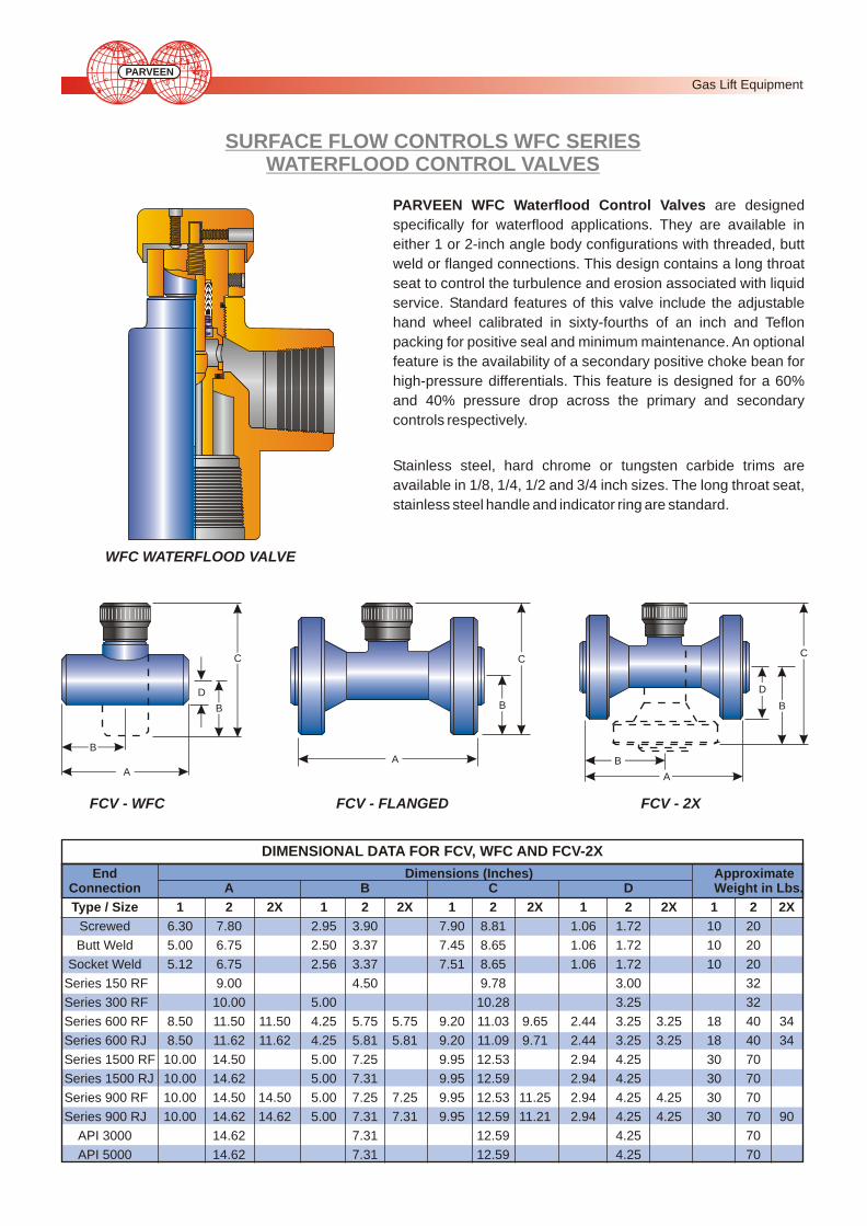
SURFACE FLOW CONTROLS WFC SERIES WATERFLOOD CONTROL VALVES
PARVEEN WFC Waterflood Control Valves are designed
specifically for waterflood applications. They are available in
either 1 or 2-inch angle body configurations with threaded, butt
weld or flanged connections. This design contains a long throat
seat to control the turbulence and erosion associated with liquid
service. Standard features of this valve include the adjustable
hand wheel calibrated in sixty-fourths of an inch and Teflon
packing for positive seal and minimum maintenance. An optional
feature is the availability of a secondary positive choke bean for
high-pressure differentials. This feature is designed for a 60%
and 40% pressure drop across the primary and secondary
controls respectively.
Stainless steel, hard chrome or tungsten carbide trims are
available in 1/8, 1/4, 1/2 and 3/4 inch sizes. The long throat seat,
stainless steel handle and indicator ring are standard.
WFC WATERFLOOD VALVE
DIMENSIONAL DATA FOR FCV, WFC AND FCV-2X
A
B
B
D
C
FCV - 2X
A
B
C
FCV - FLANGED
C
B
D
A
B
FCV - WFC
End Dimensions (Inches) Approximate Connection A B C D Weight in Lbs.
Type / Size 1 2 2X 1 2 2X 1 2 2X 1 2 2X 1 2 2X
Screwed 6.30 7.80 2.95 3.90 7.90 8.81 1.06 1.72 10 20
Butt Weld 5.00 6.75 2.50 3.37 7.45 8.65 1.06 1.72 10 20
Socket Weld 5.12 6.75 2.56 3.37 7.51 8.65 1.06 1.72 10 20
Series 150 RF 9.00 4.50 9.78 3.00 32
Series 300 RF 10.00 5.00 10.28 3.25 32
Series 600 RF 8.50 11.50 11.50 4.25 5.75 5.75 9.20 11.03 9.65 2.44 3.25 3.25 18 40 34
Series 600 RJ 8.50 11.62 11.62 4.25 5.81 5.81 9.20 11.09 9.71 2.44 3.25 3.25 18 40 34
Series 1500 RF 10.00 14.50 5.00 7.25 9.95 12.53 2.94 4.25 30 70
Series 1500 RJ 10.00 14.62 5.00 7.31 9.95 12.59 2.94 4.25 30 70
Series 900 RF 10.00 14.50 14.50 5.00 7.25 7.25 9.95 12.53 11.25 2.94 4.25 4.25 30 70
Series 900 RJ 10.00 14.62 14.62 5.00 7.31 7.31 9.95 12.59 11.21 2.94 4.25 4.25 30 70 90
API 3000 14.62 7.31 12.59 4.25 70
API 5000 14.62 7.31 12.59 4.25 70
Gas Lift Equipment PARVEEN

C Values V
Flow Coefficient at Maximum SettingsModel & Trim Size C MaximumV
ACV-5
3/4 - inch 19.31 - inch 28.0
1 1/4 - inch 35.0
ACV-8
1 - inch 30.81 1/2 - inch 61.5
2 - inch 85.8
ACV-12
2 - inch 124
3 - inch 285
SURFACE FLOW CONTROLS ACV SERIESADJUSTABLE CHOKE VALVES
PARVEEN ACV Adjustable Choke Valves have wide applications in
oil, gas and water service. Three body sizes are available to allow
proper matching of the choke to the expected flow rate. Maximum
working pressure of up to 5000 psi are standard on ACV8 and ACV-12
Valves, with higher pressures available on ACV-5 Valves. Easily read
indicator ring calibrated in sixty-fourths of an inch is designed to
provide accurate flow control. Bubble tight seal of stem is provided by
a spring-loaded Teflon packing design.
Valve and seat replacement without removal of the valve body from
the line is accomplished by simply removing the bonnet, which
requires no special tools. The seat can then be removed by hand.
All valves in this series may be equipped with either an
electric or pneumatic actuator to meet installation
requirements.
ACV-12 Series Valves feature a 3-inch maximum port and
a semi balanced stem design to reduce the torque required
to open the valve when high pressure differentials exist.
ACV-8 Series Valves feature a 2-inch maximum port and offer an
optional positive choke seat for high differential pressures.
ACV-5 Series Valves feature an 1 ¼ -inch maximum port size.
All valves in this series are available with API or ANSI flanges or with
socket weld, butt weld or threaded connections.
ACV -12 ADJUSTABLE CHOKE VALVE
SEMI-BALANCED STEM FEATURE
ACV-12 DIMENSIONAL DATAAvailable with 1 1/2, 2 or 3-inch trim.
A
B
C
Maximum 4-Inch 6-InchBody Working Inches Inches Approx. Inches Inches Approx.Style Pressure (psi) A&B C Wt. in Lbs. A&B C Wt. in Lbs.
Series 600 RF 1480 8.50 26.69 299 11.00 29.19 371
Series 600 RJ 1480 8.56 26.75 299 11.06 29.25 371
Series 900 RF 2220 9.00 27.19 327 12.00 30.19 445
Series 900 RJ 2220 9.06 27.25 327 12.06 30.25 445
Series 1500 RF 3701 10.75 28.94 363 13.87 32.06 553
Series 1500 RJ 3705 10.81 29.00 363 14.00 32.19 553
Series 2500 RF 5000 13.25 31.44 517 18.00 36.19 981
Series 2500 RJ 5000 13.44 31.63 517 16.25 34.44 981
API 2000 2000 8.56 26.75 299 11.06 29.25 371
API 3000 3000 9.06 27.25 327 11.25 29.44 445
API 5000 5000 10.81 29.00 363 12.63 30.82 553
UpstreamPressure
Gas Lift Equipment PARVEEN

SURFACE FLOW CONTROLS ACV SERIESADJUSTABLE CHOKE VALVES
ACV-8 DIMENSIONAL DATAAvailable with 1, 1 1/2 or 2 - inch trim
ACV-5 DIMENSIONAL DATAAvailable with 3/4, 1 or 1 1/4 - inch trim
ACV-8 ADJUSTABLE CHOKE VALVE
ACV-5 ADJUSTABLE CHOKE VALVE
CHOKE SEAT WITH OPTIONAL POSITIVE BEAN C
A
B
C
A
B
Maximum 2 1/2-Inch 3-Inch 4-InchBody Working Inches Inches Approx. Inches Inches Approx. Inches Inches Approx.Style Pressure (psi) A&B C Wt. in Lbs. A&B C Wt. in Lbs. A&B C Wt in Lbs.
Threaded 3000 5.00 15.19 60 5.00 15.19 70 5.44 15.63 80
Socket Weld 3600 5.00 15.19 60 5.00 15.19 70 5.44 15.63 80
Butt Weld 160 5000 5.00 15.19 60 5.00 15.19 70 5.44 15.63 80
Series 600 RF 1480 6.5 16.69 88 7.00 17.19 106 8.50 18.69 154
Series 600 RJ 1480 6.56 16.75 88 7.07 17.26 106 8.56 18.75 154
Series 900 RF 2220 8.25 18.44 132 7.50 17.69 128 9.00 19.19 182
Series 900 RJ 2220 8.31 18.50 132 7.57 17.76 128 9.06 19.25 182
Series 1500 RF 3705 8.25 18.44 132 9.25 19.44 166 10.36 20.55 218
Series 1500 RJ 3705 8.31 18.50 132 9.32 19.51 166 10.46 21.65 218
Series 2500 RF 5000 10.00 20.19 164 11.37 21.56 258 13.25 23.44 372
Series 2500 RJ 5000 10.13 20.32 164 11.50 21.69 258 13.40 23.59 372
API 2000 2000 6.56 16.75 88 7.06 17.25 106 8.56 18.75 154
API 3000 3000 8.31 18.50 132 7.57 17.76 128 9.06 19.25 182
API 5000 5000 8.31 18.50 132 9.31 19.50 166 10.81 21.00 218
MaximumWorking
Body Pressure 2 -Inch 2-1/2 Inch 3-InchStyle (psi)
Inches Inches Inches Approx. Inches Inches Approx. Inches Inches Approx.2 2 1/2 6 A&B C Wt. in Lbs. A&B C Wt. in Lbs. A&B C Wt in Lbs.
Threaded 5000 3000 5.00 13.44 35 5.00 13.44 40 5.00 13.44 45
Socket Weld 3600 5.00 13.44 35 5.00 13.44 40 5.00 13.44 45
Butt Weld 160 6000 4.50 12.94 35 5.00 13.44 40 5.00 13.44 45
Butt Weld XXH 10000 4.50 12.94 35 5.00 13.44 40 5.00 13.44 45
Series 600 RF 1480 6.38 14.82 55 6.50 14.94 60 7.00 15.44 65
Series 600 RJ 1480 6.44 14.88 55 6.56 15.00 60 7.07 15.51 65
Series 900 RF 2220 7.25 15.68 83 8.25 16.69 88 7.50 15.74 93
Series 900 RJ 2220 7.31 15.75 83 8.31 16.75 88 7.57 16.01 93
Series 1500 RF 3705 7.25 15.69 83 8.25 16.69 88 9.25 17.69 93
Series 1500 RJ 3705 7.31 15.75 83 8.31 16.75 88 9.32 17.76 93
Series 2500 RF 5000 8.75 17.19 119 10.00 18.44 144 11.31 19.75 233
Series 2500 RJ 5000 8.94 17.38 119 10.13 18.57 144 11.50 19.94 233
API 2000 2000 6.44 14.88 55 6.56 15.00 60 7.06 15.50 65
API 3000 3000 7.31 15.75 83 8.31 16.75 88 7.57 16.01 93
API 5000 5000 7.31 15.75 83 8.31 16.75 88 9.31 17.75 93
API 10000 10000 6.92 15.36 119 7.83 16.27 144 8.86 17.30 233
Gas Lift Equipment PARVEEN
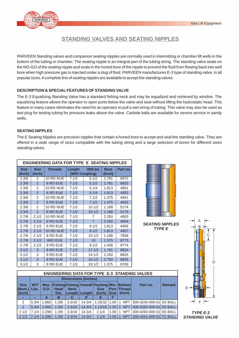
STANDING VALVES AND SEATING NIPPLES
PARVEEN Standing valves and companion seating nipples are normally used in intermitting or chamber lift wells in the
bottom of the tubing or chamber. The seating nipple is an integral part of the tubing string. The standing valve seats on
the NO-GO of the seating nipple and seals in the honed bore of the nipple to prevent the fluid from flowing back into well
bore when high pressure gas is injected under a slug of fluid. PARVEEN manufactures E-3 type of standing valve, in all
popular sizes. A complete line of seating nipples are available to accept the standing valves.
DESCRIPTION & SPECIAL FEATURES OF STANDING VALVE
The E-3 Equalizing Standing Valve has a standard fishing neck and may be equalized and retrieved by wireline. The
equalizing feature allows the operator to open ports below the valve and seat without lifting the hydrostatic head. This
feature in many cases eliminates the need for an operator to pull a wet string of tubing. This valve may also be used as
test plug for testing tubing for pressure leaks above the valve. Carbide balls are available for severe service in sandy
wells.
SEATING NIPPLES
The E Seating Nipples are precision nipples that contain a honed bore to accept and seal the standing valve. They are
offered in a wide range of sizes compatible with the tubing string and a large selection of bores for different sizes
standing valves.
SEATING NIPPLESTYPE E
TYPE E-3STANDING VALVE
A
B
C
D
E
F
Size Size Threads Length Wt/Lbs. Bore Part no.(Inch) (inch) (W/O Coupling) (Inch)
2.3/8 2 10 RD NUE 7.1/2 5.1/2 1.781 6972
2.3/8 2 8 RD EUE 7.1/2 5.1/2 1.781 6823
2.3/8 2 10 RD NUE 7.1/2 5.1/4 1.813 4901
2.3/8 2 8 RD EUE 7.1/2 5.1/4 1.813 4902
2.3/8 2 10 RD NUE 7.1/2 7.1/2 1.375 4941
2.3/8 2 8 RD EUE 7.1/2 7.1/2 1.375 4942
2.3/8 2 10 RD NUE 7.1/2 10.1/2 1.188 5174
2.3/8 2 8 RD EUE 7.1/2 10.1/2 1.188 5175
2.7/8 2.1/2 10 RD NUE 7.1/2 7 2.250 4903
2.7/8 2.1/2 8 RD EUE 7.1/2 7 2.250 4904
2.7/8 2.1/2 8 RD EUE 7.1/2 9.1/2 1.813 4906
2.7/8 2.1/2 10 RD NUE 7.1/2 9.1/2 1.813 4907
2.7/8 2.1/2 8 RD EUE 7.1/2 10.1/2 1.188 7858
2.7/8 2.1/2 8RD EUE 7.1/2 10 1.375 8773
2.7/8 2.1/2 8 RD EUE 7.1/2 9.1/2 1.438 8774
3.1/2 3 8 RD EUE 7.1/2 17.1/2 1.781 8824
3.1/2 3 8 RD EUE 7.1/2 14.1/2 2.250 8825
3.1/2 3 8 RD EUE 7.1/2 10.1/2 2.750 8826
3.1/2 3 8 RD EUE 7.1/2 19.1/2 1.375 8769
Dimensions (inches)
Size WT/ Max. Fishing Fishing Overall Packing Min. Bottom Part no. Remark (Nom.) Lbs. O.D. Head Neck Size Port Thread(Inch) Dia. Length Length (inch) Size (Inch)
– – A B C D E F
2 5.3/4 1.860 1.3/8 3.3/16 14.3/4 1.25/32 1.00 1 NPT 300-3240-000-01 SS BALL
2 5.3/4 1.860 1.3/8 3.3/16 14.3/4 1.13/16 1.00 1 NPT 300-3250-000-01 SS BALL
2 1/2 7.1/4 2.298 1.3/8 3.3/16 14.3/4 2.1/4 1.00 1 NPT 300-4260-000-01 SS BALL
2 1/2 7.1/4 2.298 1.3/8 3.3/16 14.3/4 2.1/4 1.00 1 NPT 300-4261-000-01 TC BALL
ENGINEERING DATA FOR TYPE E SEATING NIPPLES
ENGINEERING DATA FOR TYPE E-3 STANDING VALVES
Gas Lift Equipment PARVEEN

Mounted directly to the Motor Valve, the Electronic Times Cycle
Controller with the Two Stage Regulator and Filter Drip is a
compact assembly designed to provide the operator with a
reliable method of obtaining optimum control of a plunger lift
installation without frequent visual inspection and adjustment of
cycle times. The Electronic Time Cycle controller is, having
microprocessor based timer that can be programmed to display
name, date or whatever you like. The controller maintain On-Time,
OFF-Time & Delay Time.
Each timer is easily set by the operator using the dedicated keys &
the display on the front panel. Timer timings can be in hours &
minutes or as required so as to achieve maximum accuracy for
any operating condition.
The electronic controller features a rugged, watertight enclosure
with a clear, see-through front cover that allows the operator to
monitor the current cycle being timed without exposing the interior
to ambient atmospheric conditions. In addition, the internal
electronics are conformably coated for protection against
moisture laden air or corrosive gases. The coil in the solenoid
valve and current limiting components are totally encapsulated to
prevent the possibility of electric arcing in the presence of an
explosive atmosphere.
2RBF Two Stage Regulator and Filter Drip is composed of two
pressure regulators and a filter-drip pot. The primary high-
pressure regulator input up to 6000-psi supply gas and provides a
250-psi inlet supply to the secondary low-pressure regulator. The
drip pot contains a stack of felt filters, which in conjunction with the
sintered metal filter in the high-pressure regulator, provide a dry,
clean (particulates less than 4 microns) operating supply to the
pilot. The drip pot body features an extension for attachment to the
motor valve, which permits a compact, unified installation.
Switch Gauges are conventional pressure gauges with
adjustable high and low set points for controlling motor valve
operation in response to well pressure. In operation, the indicator
moves between the set point contact arms, and when the indicator
touches one of the arms, an electric circuit is completed that
generates a signal to an electronic timer, which controls the
operation of a motor valve. These contact closure signals are
used by the timer to override the programmed time cycles and
typically represent high and low tubing and casing pressure.
TIME CYCLE CONTROLLERS WITH ACCESSORIES
TIME CYCLE ELECTRONIC CONTROLLERS
2 RBF TWO STAGE REGULATOR AND FILTER DRIP
0
100
200
300
400500
600
700
800
900
1000
SWITCH GAUGE
0
10
2030
40
50
60
ELECTRONIC CONTROLLERAND MV-60 MOTOR VALVE
ELECTRONICCONTROLLER
Gas Lift Equipment PARVEEN
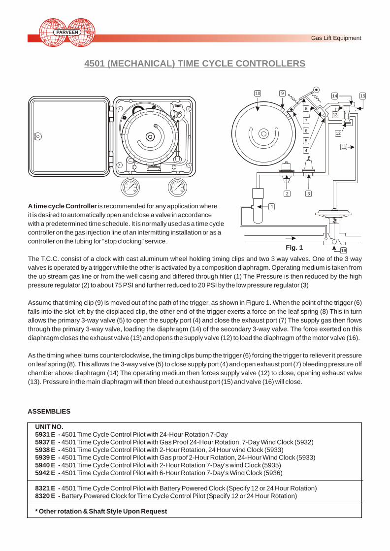
21
11
01
9
8
7
6
5
4
3 2 1
1 2 3
4
5
6 7
8
9
10
11
12
0
1020
30
40
50
0
1020
30
40
50
1
2 3
4
5
6
7
8
910
11
12
13
14 15
16
4501 (MECHANICAL) TIME CYCLE CONTROLLERS
A time cycle Controller is recommended for any application where
it is desired to automatically open and close a valve in accordance
with a predetermined time schedule. It is normally used as a time cycle
controller on the gas injection line of an intermitting installation or as a
controller on the tubing for “stop clocking” service.
The T.C.C. consist of a clock with cast aluminum wheel holding timing clips and two 3 way valves. One of the 3 way
valves is operated by a trigger while the other is activated by a composition diaphragm. Operating medium is taken from
the up stream gas line or from the well casing and differed through filter (1) The Pressure is then reduced by the high
pressure regulator (2) to about 75 PSI and further reduced to 20 PSI by the low pressure regulator (3)
Assume that timing clip (9) is moved out of the path of the trigger, as shown in Figure 1. When the point of the trigger (6)
falls into the slot left by the displaced clip, the other end of the trigger exerts a force on the leaf spring (8) This in turn
allows the primary 3-way valve (5) to open the supply port (4) and close the exhaust port (7) The supply gas then flows
through the primary 3-way valve, loading the diaphragm (14) of the secondary 3-way valve. The force exerted on this
diaphragm closes the exhaust valve (13) and opens the supply valve (12) to load the diaphragm of the motor valve (16).
As the timing wheel turns counterclockwise, the timing clips bump the trigger (6) forcing the trigger to reliever it pressure
on leaf spring (8). This allows the 3-way valve (5) to close supply port (4) and open exhaust port (7) bleeding pressure off
chamber above diaphragm (14) The operating medium then forces supply valve (12) to close, opening exhaust valve
(13). Pressure in the main diaphragm will then bleed out exhaust port (15) and valve (16) will close.
ASSEMBLIES
UNIT NO.5931 E - 4501 Time Cycle Control Pilot with 24-Hour Rotation 7-Day5937 E - 4501 Time Cycle Control Pilot with Gas Proof 24-Hour Rotation, 7-Day Wind Clock (5932) 5938 E - 4501 Time Cycle Control Pilot with 2-Hour Rotation, 24 Hour wind Clock (5933)5939 E - 4501 Time Cycle Control Pilot with Gas proof 2-Hour Rotation, 24-Hour Wind Clock (5933) 5940 E - 4501 Time Cycle Control Pilot with 2-Hour Rotation 7-Day's wind Clock (5935)5942 E - 4501 Time Cycle Control Pilot with 6-Hour Rotation 7-Day's Wind Clock (5936)
8321 E - 4501 Time Cycle Control Pilot with Battery Powered Clock (Specify 12 or 24 Hour Rotation) 8320 E - Battery Powered Clock for Time Cycle Control Pilot (Specify 12 or 24 Hour Rotation)
* Other rotation & Shaft Style Upon Request
Fig. 1
Gas Lift Equipment PARVEEN
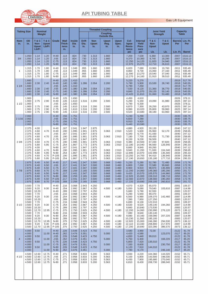
API TUBING TABLE
Nom OD T & C T & C Grade Wall Inside Drift Non Upset Upset Col- Internal T & C T & C Barreis Lin. Ft. in. in. Non- Upset Thick- Dia Dia. Upset Reg. Spec. lapse Yield Non- Upset Per Per
Upset Lb/Ft ness in. in. in. in. in. Resis- Pres- UpsetLb/Ft in. tance sure
psi psi Lb. Lb. Lin. Ft. Barrel
1.050 1.14 1.20 H-40 .113 .824 .730 1.313 1.660 7,200 7,530 6,360 13,300 .0007 1516.133/4 1.050 1.14 1.20 J-55 .113 .824 .730 1.313 1.660 9,370 10,360 8,740 18,290 .0007 1516.13
1.050 1.14 1.20 C-75 .113 .824 .730 1.313 1.660 12,250 14,120 11,920 24,940 .0007 1516.131.050 1.14 1.20 N-80 .113 .824 .730 1.313 1.660 12,970 15,070 12,710 26,610 .0007 1516.13
1.315 1.70 1.80 H-40 .113 1.049 .955 1.660 1.900 6,820 7,080 10,960 19,760 .0011 935.491 1.315 1.70 1.80 J-55 .113 1.049 .955 1.660 1.900 8,860 9,730 15,060 27,160 .0011 935.49
1.315 1.70 1.80 C-75 .113 1.049 .955 1.660 1.900 11,590 13,270 20,540 37,040 .0011 935.491.315 1.70 1.80 N-80 .113 1.049 .955 1.660 1.900 12,270 14,160 21,910 39,510 .0011 935.49
1.660 H-40 .125 1.410 5,220 5,270 .0019 517.791.660 2.30 2.40 H-40 .140 1.380 1.286 2.054 2.200 5,790 5,900 15,530 26,740 .0018 540.55
1 1/4 1.660 J-55 .125 1.410 6,790 7,250 .0019 517.791.660 2.30 2.40 J-55 .140 1.380 1.286 2.054 2.200 7,530 8,120 21,360 36,770 .0018 540.551.660 2.30 2.40 C-75 .140 1.380 1.286 2.054 2.200 9,840 11,070 29,120 50,140 .0018 540.551.660 2.30 2.40 N-80 .140 1.380 1.286 2.054 2.200 10,420 11,810 31,060 53,480 .0018 540.55
1.900 H-40 .125 1.650 4,450 4,610 .0026 378.111.900 2.75 2.90 H-40 .145 1.610 1.516 2.200 2.500 5,290 5,340 19,090 31,980 .0025 397.14
1 1/2 1.900 J-55 .125 1.650 5,790 6,330 .0026 378.111.900 2.75 2.90 J-55 .145 1.610 1.516 2.200 2.500 6,870 7,350 26,250 43,970 .0025 397.141.900 2.75 2.90 C-75 .145 1.610 1.516 2.200 2.500 8,990 10,020 35,800 59,960 .0025 397.141.900 2.75 2.90 N-80 .145 1.610 1.516 2.200 2.500 9,520 10,680 38,180 63,960 .0025 397.14
2.063 H-40 .156 1.751 5,240 5,290 .0030 335.752 1/16 2.063 J-55 .156 1.751 6,820 7,280 .0030 335.75
2.063 C-75 .156 1.751 8,910 9,920 .0030 335.752.063 N-80 .156 1.751 9,440 10,590 .0030 335.75
2.375 4.00 H-40 .167 2.041 1.947 2.875 4,880 4,920 30,130 .0040 247.122.375 4.60 4.70 H-40 .190 1.995 1.901 2.875 3.063 2.910 5,520 5,600 35,960 52,170 .0039 258.652.375 4.00 J-55 .167 2.041 1.947 2.873 6,340 6,770 41,430 .0040 247.122.375 4.60 4.70 J-55 .190 1.995 1.901 2.875 3.063 2.910 7,180 7,700 49,450 71,730 .0039 258.652.375 4.00 C-75 .167 2.041 1.947 2.875 8,150 9,230 56,500 .0040 247.12
2 3/8 2.375 4.60 4.70 C-75 .190 1.995 1.901 2.875 3.063 2.910 9,380 10,500 67,430 97,820 .0039 258.652.375 5.80 5.95 C-75 .254 1.867 1.773 2.875 3.063 2.910 12,180 14,040 96,560 126,940 .0034 295.332.375 4.00 N-80 .167 2.041 1.947 2.875 8,660 9,840 60,260 .0040 247.122.375 4.60 4.70 N-80 .190 1.995 1.901 2.875 3.063 2.910 9,940 11,200 71,930 104,340 .0039 258.652.375 5.80 5.95 N-80 .254 1.867 1.773 2.875 3.063 2.910 12,890 14,970 102,990 135,400 .0034 295.332.375 4.60 4.70 P-105 .190 1.995 1.901 2.875 3.063 2.910 13,250 14,700 94,410 136,940 .0039 258.652.375 5.80 5.95 P-105 .254 1.867 1.773 2.875 3.063 2.910 17,190 19,650 135,180 177,710 .0034 295.33
2.875 6.40 6.50 H-40 .217 2.441 2.347 3.500 3.668 3.460 5,230 5,280 52,780 72,480 .0058 172.762.875 6.40 6.50 J-55 .217 2.441 2.347 3.500 3.668 3.460 6,800 7,260 72,580 99,660 .0058 172.762.875 6.40 6.50 C-75 .217 2.441 2.347 3.500 3.668 3.460 8.900 9,910 98,970 135,900 .0058 172.76
2 7/8 2.875 8.60 8.70 C-75 .308 2.259 2.165 3.500 3.668 3.460 12,200 14,060 149,360 185,290 .0050 201.722.875 6.40 6.50 N-80 .217 2.441 2.347 3.500 3.668 3.460 9,420 10,570 105,570 144,960 .0058 172.762.875 8.60 8.70 N-80 .308 2.259 2.165 3.500 3.668 3.460 12,920 15,000 159,310 198,710 .0050 201.722.875 6.40 6.50 P-105 .217 2.441 2.347 3.500 3.668 3.460 12,560 13,870 138,560 190,260 .0058 172.762.875 8.60 8.70 P-105 .308 2.259 2.165 3.500 3.668 3.460 17,220 19,690 209,100 260,810 .0050 201.72
3.500 7.70 H-40 .216 3.068 2.943 4.250 4,070 4,320 65,070 .0091 109.373.500 9.20 9.30 H-40 .254 2.992 2.867 4.250 4.500 4.180 5,050 5,080 79,540 103,610 .0087 114.993.500 10.20 H-40 .289 2.992 2.797 4.250 5,680 5,780 92,550 .0083 120.573.500 7.70 J-55 .216 3.068 2.943 4.250 5,290 5,940 89,470 .0091 109.373.500 9.20 9.30 J-55 .254 2.992 2.867 4.250 4.500 4.180 6,560 6,980 109,370 142,460 .0087 114.993.500 10.20 J-55 .289 2.992 2.797 4.250 7,390 7,950 127,250 .0083 120.573.500 7.70 C-75 .216 3.068 2.943 4.250 6,690 8,100 122,010 .0091 109.37
3 1/2 3.500 9.20 9.30 C-75 .254 2.992 2.867 4.250 4.500 4.180 8,530 9,520 149,140 194,260 .0087 114.993.500 10.20 C-75 .289 2.992 2.797 4.250 9,660 10,840 173,530 .0083 120.573.500 12.70 12.95 C-75 .375 2.750 2.625 4.250 4.500 4.180 12,200 14,060 230,990 276,120 .0073 136.123.500 7.70 N-80 .216 3.068 2.943 4.250 7,080 8,640 130,140 .0091 109.373.500 9.20 9.30 N-80 .254 2.992 2.867 4.250 4.500 4.180 9,080 10,160 159,090 207,220 .0087 114.993.500 10.20 N-80 .289 2.992 2.797 4.250 10,230 11,560 185,100 .0083 120.573.500 12.70 12.95 N-80 .375 2.750 2.625 4.250 4.500 4.180 12,920 15,000 246,390 294,530 .0073 136.123.500 9.20 9.30 P-105 .254 2.992 2.867 4.250 4.500 4.180 12,110 13,330 208,800 217,970 .0087 114.993.500 12.70 12.95 P-105 .375 2.750 2.625 4.250 4.500 4.180 17,200 19,690 323,390 386,570 .0073 136.12
4.000 9.50 H-40 .226 3.548 3.423 4.750 3,580 3,960 72,00 .0122 81.784.000 11.00 H-40 .262 3.476 3.351 5.000 4,420 4,580 123,070 .0117 85.204.000 9.50 J-55 .226 3.548 3.423 4.750 4,650 5,440 99,010 .0122 81.78
4 4.000 11.00 J-55 .262 3.476 3.351 5.000 5,750 6,300 169,220 .0117 85.204.000 9.50 C-75 .226 3.548 3.423 4.750 5,800 7,420 135,010 .0122 81.784.000 11.00 C-75 .262 3.476 3.351 5.000 7,330 8,600 230,750 .0117 85.204.000 9.50 N-80 .226 3.548 3.423 4.750 6,120 7,910 144,010 .0122 81.784.000 11.00 N-80 .262 3.476 3.351 5.000 7,780 9,170 246,140 .0117 85.20
4.500 12.60 12.75 H-40 .271 3.958 3.833 5.200 5.563 3,930 4,220 104,360 144,020 .0152 65.714 1/2 4.500 12.60 12.75 J-55 .271 3.958 3.833 5.200 5.563 5,100 5,800 143,500 198,030 .0152 65.71
4.500 12.60 12.75 C-75 .271 3.958 3.833 5.200 5.563 6,430 7,900 195,680 270,040 .0152 65.714.500 12.60 12.75 N-80 .271 3.958 3.833 5.200 5.563 6,810 8,430 208,730 288,040 .0152 65.71
Tubing Size Nominal Weight
Threaded Coupling Joint Yield Strength
Capacity Table Coupling
Outside Dia.
Gas Lift Equipment PARVEEN
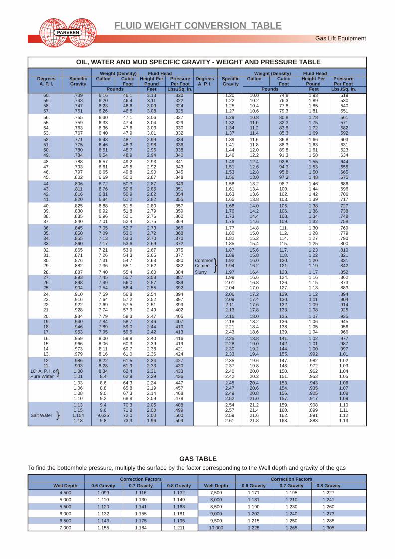
FLUID WEIGHT CONVERSION TABLE
OIL, WATER AND MUD SPECIFIC GRAVITY - WEIGHT AND PRESSURE TABLE
GAS TABLE
To find the bottomhole pressure, multiply the surface by the factor corresponding to the Well depth and gravity of the gas
Correction Factors Correction Factors
Well Depth 0.6 Gravity 0.7 Gravity 0.8 Gravity Well Depth 0.6 Gravity 0.7 Gravity 0.8 Gravity
4,500 1.099 1.116 1.132 7,500 1.171 1.195 1.227
5,000 1.110 1.130 1.149 8,000 1.181 1.210 1.241
5,500 1.120 1.141 1.163 8,500 1.190 1.230 1.260
6,000 1.132 1.155 1.181 9,000 1.202 1.240 1.273
6,500 1.143 1.175 1.195 9,500 1.215 1.250 1.285
7,000 1.155 1.184 1.211 10,000 1.225 1.265 1.305
Weight (Density) Fluid Head Weight (Density) Fluid HeadDegrees Specific Gallon Cubic Height Per Pressure Degrees Specific Gallon Cubic Height Per Pressure A. P. I. Gravity Foot Pound Per Foot A. P. I. Gravity Foot Pound Per Foot
Pounds Feet Lbs./Sq. In. Pounds Feet Lbs./Sq. In.
60. .739 6.16 46.1 3.13 .320 1.20 10.0 74.8 1.93 .51959. .743 6.20 46.4 3.11 .322 1.22 10.2 76.3 1.89 .53058. .747 6.23 46.6 3.09 .324 1.25 10.4 77.8 1.85 .54057. .751 6.26 46.8 3.08 .325 1.27 10.6 79.3 1.81 .551
56. .755 6.30 47.1 3.06 .327 1.29 10.8 80.8 1.78 .56155. .759 6.33 47.4 3.04 .329 1.32 11.0 82.3 1.75 .57154. .763 6.36 47.6 3.03 .330 1.34 11.2 83.8 1.72 .58253. .767 6.40 47.9 3.01 .332 1.37 11.4 85.3 1.69 .592
52. .771 6.43 48.1 2.99 .334 1.39 11.6 86.8 1.66 .60351. .775 6.46 48.3 2.98 .336 1.41 11.8 88.3 1.63 .63150. .780 6.51 48.7 2.96 .338 1.44 12.0 89.8 1.61 .62349. .784 6.54 48.9 2.94 .340 1.46 12.2 91.3 1.58 .634
48. .788 6.57 49.2 2.93 .341 1.49 12.4 92.8 1.55 .64447. .793 6.61 49.5 2.92 .343 1.51 12.6 94.3 1.53 .65546. .797 6.65 49.8 2.90 .345 1.53 12.8 95.8 1.50 .66545. .802 6.69 50.0 2.87 .348 1.56 13.0 97.3 1.48 .675
44. .806 6.72 50.3 2.87 .349 1.58 13.2 98.7 1.46 .68643. .811 6.76 50.6 2.85 .351 1.61 13.4 100. 1.44 .69642. .816 6.81 50.9 2.82 .354 1.63 13.6 102. 1.42 .70641. .820 6.84 51.2 2.82 .355 1.65 13.8 103. 1.39 .717
40. .825 6.88 51.5 2.80 .357 1.68 14.0 105. 1.38 .72739. .830 6.92 51.8 2.79 .359 1.70 14.2 106. 1.36 .73838. .835 6.96 52.1 2.76 .362 1.73 14.4 108. 1.34 .74837. .840 7.01 52.4 2.75 .364 1.75 14.6 109. 1.32 .758
36. .845 7.05 52.7 2.73 .366 1.77 14.8 111. 1.30 .76935. .850 7.09 53.0 2.72 .368 1.80 15.0 112. 1.28 .77934. .855 7.13 53.3 2.70 .370 1.82 15.2 114. 1.27 .79033. .860 7.17 53.6 2.69 .372 1.85 15.4 115. 1.25 .800
32. .865 7.21 53.9 2.67 .375 1.87 15.6 117. 1.23 .81031. .871 7.26 54.3 2.65 .377 1.89 15.8 118. 1.22 .82130. .876 7.31 54.7 2.63 .380 Common 1.92 16.0 120. 1.20 .83129. .882 7.36 55.1 2.62 .382 Cement 1.94 16.2 121. 1.19 .842
28. .887 7.40 55.4 2.60 .384 Slurry 1.97 16.4 123. 1.17 .85227. .893 7.45 55.7 2.58 .387 1.99 16.6 124. 1.16 .86226. .898 7.49 56.0 2.57 .389 2.01 16.8 126. 1.15 .87325. .904 7.54 56.4 2.55 .392 2.04 17.0 127. 1.13 .883
24. .910 7.59 56.8 2.54 .394 2.06 17.2 129. 1.12 .89423. .916 7.64 57.2 2.52 .397 2.09 17.4 130. 1.11 .90422. .922 7.69 57.5 2.51 .399 2.11 17.6 132. 1.09 .91421. .928 7.74 57.9 2.49 .402 2.13 17.8 133. 1.08 .925
20. .934 7.79 58.3 2.47 .405 2.16 18.0 135. 1.07 .93519. .940 7.84 58.7 2.46 .407 2.18 18.2 136. 1.06 .94518. .946 7.89 59.0 2.44 .410 2.21 18.4 138. 1.05 .95617. .953 7.95 59.5 2.42 .413 2.43 18.6 139. 1.04 .966
16. .959 8.00 59.8 2.40 .416 2.25 18.8 141. 1.02 .97715. .966 8.06 60.3 2.39 .419 2.28 19.0 142. 1.01 .98714. .973 8.11 60.7 2.38 .421 2.30 19.2 144. 1.00 .99713. .979 8.16 61.0 2.36 .424 2.33 19.4 155. .992 1.01
12. .986 8.22 61.5 2.34 .427 2.35 19.6 147. .982 1.0211. .993 8.28 61.9 2.33 .430 2.37 19.8 148. .972 1.03
O10 A. P. I. or 1.00 8.34 62.4 2.31 .433 2.40 20.0 150. .962 1.04Pure Water 1.01 8.4 62.8 2.29 .436 2.42 20.2 151. .953 1.05
1.03 8.6 64.3 2.24 .447 2.45 20.4 153. .943 1.061.06 8.8 65.8 2.19 .457 2.47 20.6 154. .935 1.071.08 9.0 67.3 2.14 .468 2.49 20.8 156. .925 1.081.10 9.2 68.8 2.09 .478 2.52 21.0 157. .917 1.09
1.13 9.4 70.3 2.05 .488 2.54 21.2 159. .908 1.101.15 9.6 71.8 2.00 .499 2.57 21.4 160. .899 1.11
Salt Water 1.154 9.625 72.0 2.00 .500 2.59 21.6 162. .891 1.121.18 9.8 73.3 1.96 .509 2.61 21.8 163. .883 1.13
Gas Lift Equipment PARVEEN

Acre = 43,560. Square feet
Acre = 4,047. Square meter
Acre foot = 7,758. Barrels
Atmosphere = 33.94 Feet of water
Atmosphere = 29.92 Inches of mercury
Atmosphere = 760.0 Millimeters of mercury
Atmosphere = 14.70 Pounds per square inch
Bar = 14.504 Pounds per square inch
Barrel = 5.6146 Cubic feet
Barrel = 42.0 Gallons OBarrel of water @ 60 f = .1588 Metric ton
Barrel (36O A. P. I.) = .1342 Metric ton
Barrel per hour = .0936 Cubic feet per minute
Barrel per hour = .700 Gallon per minute
Barrel per hour = 2.695 Cubic inches per second
Barrel per day = .02917 Gallon per minute
British Thermal Unit = .2520 Kilogram calorie
British Thermal Unit = .2928 Watt hour
B.T.U. per minute = .02356 Horse power
Centimeter = .3937 Inch
Centimeter of mercury = .1934 Pound per square inch
Cubic centimeter = .06102 Cubic inch
Cubic foot = .1781 Barrel
Cubic foot = 7.4805 Gallons (U. S.)
Cubic foot = .02832 Cubic meter
Cubic foot = .9091 Sacks cement (Set)
Cubic foot per minute = 10.686 Barrels per hour
Cubic foot per minute = 28.800 Cubic inches per second
Cubic foot per minute = 7.481 Gallons per minute
Cubic inch = 16.387 Cubic centimeters
Cubic meter = 6.2897 Barrels
Cubic meter = 35.341 Cubic feet
Cubic meter = 1.308 Cubic yards
Cubic meter = 264.20 Gallons (U. S.)
Cubic meter, normal = 34.77 Cubic feet, standard
Cubic yard = 4.8089 Barrels
Cubic yard = 46.656 Cubic inches
Cubic yard = .7646 Cubic meter
Foot = 30.48 Centimeters
Foot = .3048 MeterOFoot of water @ 60 F = .4331 Pound per square inch
Foot per second = .68182 Mile per hour
Foot pound = .001286 British Thermal Unit
Foot pound per second = .001818 Horse power
Gallon (U. S.) = .02381 Barrel
Gallon (U. S.) = .1337 Cubic feet
Gallon (U. S.) = 231.000 Cubic inches
Gallon (U. S.) = 3.785 Liters
Gallon (U. S.) = .8327 Gallon (Imperial)
Gallon (U. S.) = 0.003785 Cubic meters
Gallon (Imperial) = 1.2009 Gallon (U. S.)
Gallon (Imperial) = 277.274 Cubic inches
Gallon per minute = 1.429 Barrels per hour
Gallon per minute = .1337 Cubic feet per minute
Gallon per minute = 34.286 Barrels per day
Gram = .03527 Ounce
Horse power = 42.44 T. U.’s per minute
Horse power = 33,000. Foot-pounds per minute
Horse power = 550. Foot pounds per seconds
Horse power = 1.014 Horse power (metric)
CONVERSION FACTORS APPLYING TO OIL COUNTRY CALCULATIONS
Horse power = .7457 Kilo Watt
Horse power hour = 2,547. British Thermal Unit
Inch = 2.540 Centimeters
Inch of mercury = 1.134 Feet of water
Inch of mercury = .4912 Pound per square inch OInch of water 60 F = .0361 Pound per square inch
Kilogram = 2.2046 Pounds
Kilogram calorie = 3.968 British Thermal Units
Kilogram per sq. centimeter = 14.223 Pounds per square inch
Kilometer = 3,281. Feet
Kilometer = .2614 Miles
Kilo Pascal (KPa) = 0.145 Pounds per square inch
Kilo weight = 1.341 Horse power
Liter = .2642 Gallon
Liter = 1.0567 Quarters
Mega Pascal (MPa) = 145.03 Pound per square inch
Meter = 3.281 Feet
Meter = 39.37 Inches
Mile = 5,280. Feet
Mile = 1.609 Kilometers
Mile per hour = 1.4667 Feet per second
Ounce (Avoirdupois) = 28.3495 Grams
Part per Million = .05835 Grain per gallon
Part per Million = 8.345 Pounds per million gallon
Pascal (Pa) = 0.000145 Pounds per square inch
Pounds = 7,000. Grains
Pounds = .4536 Kilogram OPound per square inch = 2.309 Feet of water 60 F
Pound per square inch = 2.0353 Inches of mercury
Pound per square inch = 51.697 Millimeters of mercury
Pound per square inch = .0703 Kilograms per sq. cms.
Pound per square inch = 0.0689 Bar
Pound per square inch = .006895 Mega Pascal (MPa)
Pound per square inch = 6.895 Kilo Pascal (KPa)
Pound per square inch = 6895. Pascal (Pa)
Pound per million gallons = .00700 Grain per gallon
Pound per million gallons = .11982 Parts per million
Quarter (Liquid) = .946 Liter
Sack cement (set) = 1.1 Cubic feet
Square centimeter = 1.550 Square inch
Square foot = .929 Square meter
Square inch = 6.452 Square centimeters
Square kilometer = .3861 Square mile
Square meter = 10.67 Square feet
Square mile = 2.590 Square kilometers OTemperature Centigrade = 5/9 (Temperature F -32)OTemperature Fahrenheit = 9/5 (Temperature C) +32
OTemp. Absolute (Kelvin) = Temperature C +273OTemp. Absolute (Rankine) = Temperature F +460
Ton (Long) = 2,240. Pounds
Ton (Metric) = 2,205. Pounds
Ton (Short or Net) = 2,000. Pouds
Ton (Metric) = 1.102 Tons (Short on Net)
Ton (Metric) = 1,000. Kilograms OTon (Metric) = 6.297 Barrels of water @ 60 F
OTon (Metric) = 7,454. Barrels (36 A. P. I.)
Ton (Short or Net) = .907 Ton (Metric)
Watt - Hour = 3,415. British Thermal Unit
Yard = .9144 Meter
Metric P. I. in 3M / D
2Kg / Cmx .428 = US P. I. in BPD / PSI Metric GLR in
3NM / D
3Mx .5.529 = US GLR in scf / bbI
Gas Lift Equipment PARVEEN
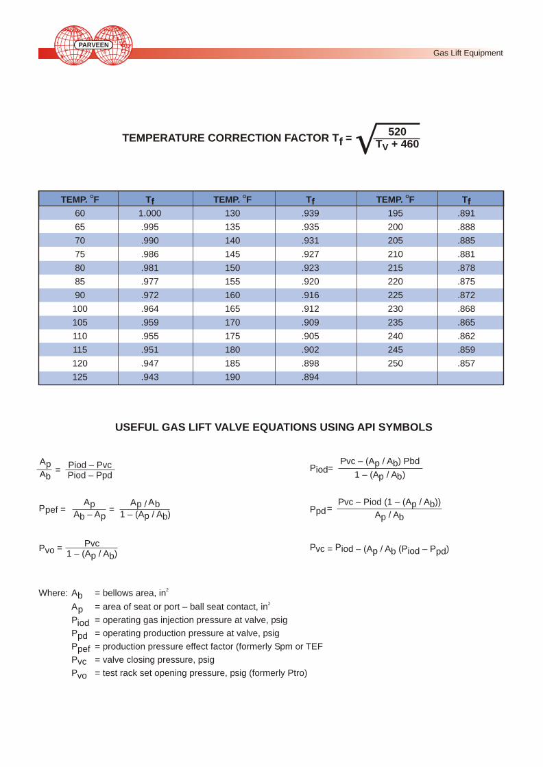
TEMPERATURE CORRECTION FACTOR T =f520
T + 460V
USEFUL GAS LIFT VALVE EQUATIONS USING API SYMBOLS
P Pvc = iod – (A / A (P – P )p iodb pd
ApAb
Piod – PvcPiod – Ppd
=
PpefAp
A – Apb
AAp / b1 – (A / A )p b
= =
PvoPvc
1 – (A / A )p b=
PiodPvc – (A / A ) Pbdp b
1 – (A / A )p b=
PpdPvc – Piod (1 – (A / A ))p b
A / Ap b=
2Where: A = bellows area, inb2A = area of seat or port – ball seat contact, inp
P = operating gas injection pressure at valve, psigiodP = operating production pressure at valve, psigpdP = production pressure effect factor (formerly Spm or TEFpefP = valve closing pressure, psigvcP = test rack set opening pressure, psig (formerly Ptro)vo
O O OTEMP. F T TEMP. F T TEMP. F Tf f f
60 1.000 130 .939 195 .891
65 .995 135 .935 200 .888
70 .990 140 .931 205 .885
75 .986 145 .927 210 .881
80 .981 150 .923 215 .878
85 .977 155 .920 220 .875
90 .972 160 .916 225 .872
100 .964 165 .912 230 .868
105 .959 170 .909 235 .865
110 .955 175 .905 240 .862
115 .951 180 .902 245 .859
120 .947 185 .898 250 .857
125 .943 190 .894
Gas Lift Equipment PARVEEN

VALVE AND SEAT SPECIFICATIONS
LN Series Valve VALVE AND SEAT SPECIFICATIONS
N Series Valve VALVE AND SEAT SPECIFICATIONS
* Fe = Dynamic Ap / Ab
RV Series ValvesPERFORMANCE DATA AND VALVE SPECIFICATIONS
The maximum flow rate can be calculated using the following formula. Use Cv from the chart for the particular valve and choke size used.
Q = 1780 C (Pcf – P ) Pv tmax t Gtv
Q = MCF / Day
G = Specific Gravity (Air = 1)OT = Valve Temperature (460+ F)v
C = Coefficient of Flow (Discharge)vP = Flowing Casing Pressure of Valve cfP = Tubing Pressure t
WF Series Valve VALVE AND SEAT SPECIFICATIONSWF-14R WFM-14R
Ball Seat Bellows Ap/Ab2Dia. Angle Area, In
O16/64 37 .150O18/64 37 .12 .183O20/64 37 Adj. Range .233O24/64 37 0-1500 psi .333
Ball Seat Bellows Ap/Ab Bellows Ap/Ab2 2Dia. Angle Area, In Area, In
O16/64 37 .058 .078O20/64 37 .31 .090 .23 .122O24/64 38 Adj. Range .135 Adj. Range .183O24/64 45 0-800 .177 600-1500 .239O32/64 38 psi .242 psi .326O32/64 45 .316 .426
No. of 1/8-inch RVM-16RD Orifices Cv Area Equiv. Dia
1 .0102 .0123 .0125
2 .0162 .0245 .0177
3 .0202 .0368 .0217
4 .0222 .0491 .0250
Type Bellows Port Dia. Ap/Ab2Valve Area In (inches)
8/64 .017
10/64 .020
N-15 & 12/64 .038
N-15R 77 16/64 .067
20/64 .103
24/64 .148
28/64 .200
32/64 .261
8/64 .043
NM-16 & 12/64 .094
NM-16 R .31 16/64 .166
20/64 .256
24/64 .368
Type Trim Port Dia. *Size (inches) Fe
Small 0.582 0.34LN-21R Medium 0.670 0.46
Large 0.775 0.60
Small 0.300 0.27LNM-31R Medium 0.360 0.38
Large 0.410 0.48
Gas Lift Equipment PARVEEN
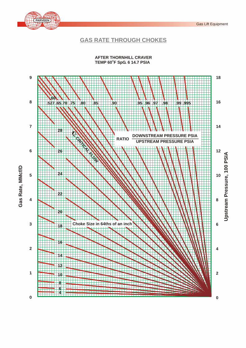
GAS RATE THROUGH CHOKES
46
10
12
14
16
18
20
22
24
26
28
8
.527 .995.99.98.97.96.95.90.85.80.75.70.65.60
RATIO DOWNSTREAM PRESSURE PSIA
UPSTREAM PRESSURE PSIA
Choke Size in 64ths of an inch
CT
AF
O
RI
ICL
LW
18
16
14
12
10
8
6
4
2
0
9
8
7
6
5
4
3
2
1
0
Ga
s R
ate
, M
Mc
f/D
Up
str
ea
m P
res
su
re, 1
00
PS
IA
AFTER THORNHILL CRAVEROTEMP 60 F SpG. 6 14.7 PSIA
Gas Lift Equipment PARVEEN
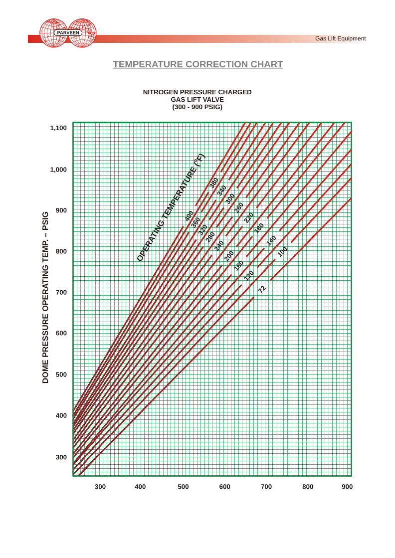
TEMPERATURE CORRECTION CHART
NITROGEN PRESSURE CHARGED GAS LIFT VALVE (300 - 900 PSIG)
DO
ME
PR
ES
SU
RE
OP
ER
AT
ING
TE
MP. –
PS
IG
1,100
1,000
900
800
700
600
500
400
300
300 400 500 600 700 800 900
400
360
320
280
240
002
160
120
72
380
403
300
260
220
810
140
100
O
OP
ER
ATIN
G T
EM
PE
RATU
R
(F)
E
Gas Lift Equipment PARVEEN

TEMPERATURE CORRECTION CHART
NITROGEN PRESSURE CHARGED GAS LIFT VALVE (700 - 2000 PSIG)
0DOME PRESSURE AT 60 F – 100 PSIG
DO
ME
PR
ES
SU
RE
OP
ER
AT
ING
TE
MP. –
PS
IG 400
360
320
280
240
200
160
120
72
380
403
030
260
220
180
014
001
O
EE
OP
ER
ATIN
G T
MP
RA
TU
RE
(F)
7 8 9 10 11 12 13 14 15 16 17 18 19 20
27
26
10
11
12
13
14
15
16
17
18
19
20
21
22
23
24
25
Gas Lift Equipment PARVEEN

Parveen GLV test bench is manufactured from heavy duty stainless steel sheet metal, pressure gauges with all
stainless steel fittings and valves. Test bench is designed to meet most of the test / calibration requirements of API spec.
11 V1 for GLV's. This is combination of typical sleeve tester, typical encapsulated stem-seat leakage tester and also
built-in pressure chamber (ager). Our GLV test bench provides testing facility for following parameters:
1. Charging bellows to specific nitrogen pressure
2. Valve opening pressure
3. Valve closing pressure
4. Valve leakage test
5. Hydrostatic valve test
CALIBRATION & TESTING OF GAS LIFT VALVES
TOOLS/ACCESSORIES WITH TEST BENCH
B) Pressure Releasing & Charging ToolA) Chamber Valve Removing
PARVEEN
Calibration of Gas Lift Valves

Parveen Test Bench is designed in accordance with following design parameters as per API spec. 11 V1.
Design parameters:
1. Valve Size: 1" and 11/2" conventional & retrievable nitrogen charged gas lift valves.
2. System Accuracy: + 100 psi for aging chamber + 5 psi for calibration and charging of gas lift valves.
3. Maximum Bellow Charge: 2000psi
4. Maximum Chamber Hydro test: 5000 psi
5. Valve/Bellow Stabilizing /Storing Capacity: 10 nos (max.)
DESIGN PARAMETERS
CONSTRUCTIONAL FEATURES OF GLV TEST BENCH
There are four sections of test bench as follows :
1. Gauge Section
2. Chamber Section
3. Control Valves Section and
4. Inlet Section
i) PRESSURE GAUGE SECTION
Used in the test bench as follows:
A) Hydraulic Pressure Gauge:
(Range: 0-10,000 psi)
This pressure gauge shows the pressure
in hydraulic pressure chamber (ager).
B) Casing Pressure Gauge:
(Range: 0-2000 psi)
This pressure gauge shows casing
pressure in typical sleeve tester and typical
encapsulated tester for stemseat leakage
test of gas lift valve.
C) Tubing pressure gauge (Range: 0-2000psi)
To indicate tubing pressure in the glv this pressure gauge is used.
PARVEEN
Calibration of Gas Lift Valves

As shown in above figure there are three testing devices
provided in our GLV test bench
A) Hydraulic Pressure Chamber (Ager)
B) Encapsulated Stem-seat Leakage Tester
C) Sleeve Tester
ii) CHAMBER SECTION
There are nine control valves systematically arranged
as shown in above figure having specific functions of
each one, used to operate test bench for different
testings of GLV.
1. Hydraulic Exhaust/Bleed
2. Tubing Pressure Exhaust
3. On/Off For Sleeve, Stem-Seat Leakage
4. Gas Pressure Tubing
5. Leak Test
6. Casing Pressure On
7. For Sleeve Tester
8. Casing Pressure Exhaust
9. Hydraulic Pressure On/Off
iii) CONTROL VALVE SECTION
PARVEEN
Calibration of Gas Lift Valves

In this section there are three inlet provided with ½”
NPT for external connection and also two outlets/
exhausts provided.
1. N2 Inlet:
From this inlet we can give nitrogen supply
upto 2000 psi for GLV leak test and for valve
setting & bellow stabilization.
2. Orifice:
Here 1/16" orifice is provided for tubing pressure
exhaust.
3. Hydraulic Exhaust:
It is used to exhaust hydraulic pressure in ager.
4) Air Inlet:
Air supply of 100 psi from air hydraulic pump can be applied through this inlet.
5) water inlet:
From this inlet we can supply water for inside pressure pump.
iv) INLET SECTION
Pressure Chamber (Ager)
Tills device is a water filled chamber for maximum 5000 psi pressure. The Gas Lift Valves are inserted into the chamber
and subjected to a predetermined external pressure for some length of time and number of cycles.
Test Rack
This equipment is used to set the opening or closing pressure of nitrogen charged valves. There are two types in use:
Typical sleeve tester (M-010) and typical encapsulated stem and seat leakage tester (M-011), those are arranged in our
test bench very conveniently.
Water Bath
This is a water filled container where several gas lift valves are immersed in the water to bring them to a predetermined
controlled temperature. Since most gas lift installations design the GLV set pressure at 16°c, the temperature of the
water bath is usually controlled at 16°c.
APPARATUS
PARVEEN
Calibration of Gas Lift Valves

Introduction:
The purpose of the gas lift valve probe tester is to determine the relative "stiffness" of a gas lift valve and to determine the
maximum available travel of the stem top. When gas pressure is admitted to the tester, it acts on the full area of the
valve bellows to lift the stem off the seat. When this pressure increased, the stem tip lifts further from the seat. By using
the valve probe tester, an accurate measure of the stem tip travel per pressure increase can be determined and the
results tabulated and plotted.
When the pressure is plotted as the ordinate and the stem tip travel as the abscissa, a relatively straight line will be
generated for the majority of the stem tip travel. The slope of this line is an indication of the "stiffness" of the valve. The
numerical value of the slope is called the bellows assembly load rate (blr) and is measured in psig/inch [kpa/mm]. In this
context, the "bellows assembly" includes the bellows and the system which applies a load to hold the valve stem on the
seat. The higher the load rate, the "stiffer"the valve and inversely, the lower the lower the load rate, the "softer" the valve.
If the above is done with the same valve, except that opening pressure (dome charge or spring setting) is varied, then
the effect of dome charge pressure or spring setting on the bellows assembly load rate can be compared for the same
type valve when set for different opening pressures. The bellows assembly load rate is a practical value that can be
used to compare different types of valves or when evaluating the same valve under different load conditions and when
designing the gas lift installation.
PROBE TESTER
VALVE
TESTER
PRESSURE GAUGE
BLEED
INSULATED BUSHING
MICROMETER
METER
PARVEEN
Calibration of Gas Lift Valves