complex networks using static routes complex networks using static routes … · 2014-02-20 ·...
TRANSCRIPT
Complex Networks using static routesComplex Networks Using Static Routes
1
Using Static Routes
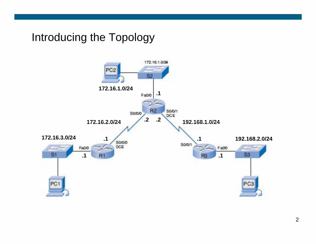
Introducing the Topology
172.16.2.0/24
172.16.1.0/24
192.168.1.0/24
.1
.2 .2
2
172.16.3.0/24
172.16.2.0/24 192.168.1.0/24
192.168.2.0/24
.1 .1
.1
.2 .2
.1
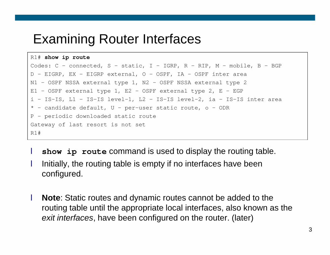
Examining Router InterfacesR1# show ip routeCodes: C - connected, S - static, I - IGRP, R - RIP, M - mobile, B - BGPD - EIGRP, EX - EIGRP external, O - OSPF, IA - OSPF inter areaN1 - OSPF NSSA external type 1, N2 - OSPF NSSA external type 2E1 - OSPF external type 1, E2 - OSPF external type 2, E - EGPi - IS-IS, L1 - IS-IS level-1, L2 - IS-IS level-2, ia - IS-IS inter area* - candidate default, U - per-user static route, o - ODRP - periodic downloaded static routeGateway of last resort is not set
l show ip route command is used to display the routing table. l Initially, the routing table is empty if no interfaces have been
configured.
l Note: Static routes and dynamic routes cannot be added to the routing table until the appropriate local interfaces, also known as the exit interfaces, have been configured on the router. (later)
3
Gateway of last resort is not setR1#
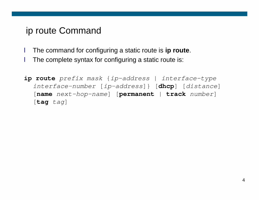
ip route Command
l The command for configuring a static route is ip route. l The complete syntax for configuring a static route is:
ip route prefix mask {ip-address | interface-type interface-number [ip-address]} [dhcp] [distance] [name next-hop-name] [permanent | track number] [tag tag][tag tag]
4
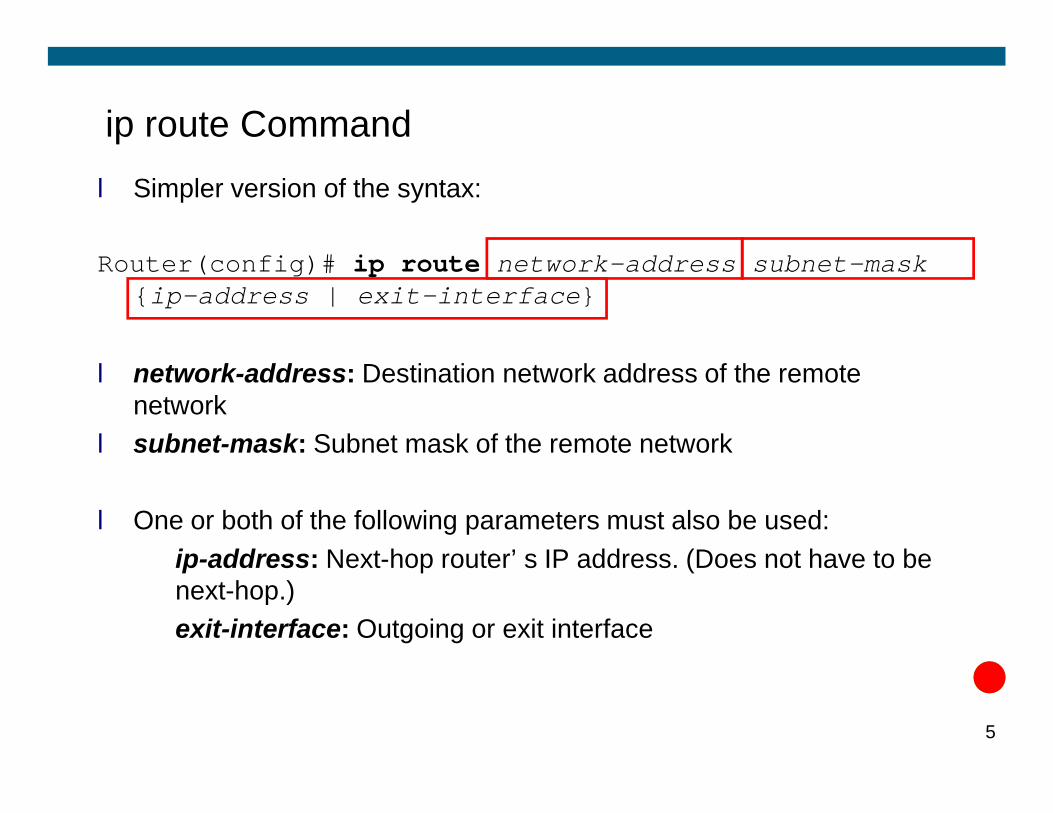
ip route Commandl Simpler version of the syntax:
Router(config)# ip route network-address subnet-mask {ip-address | exit-interface}
l network-address: Destination network address of the remote network network
l subnet-mask: Subnet mask of the remote network
l One or both of the following parameters must also be used:ü ip-address: Next-hop router’s IP address. (Does not have to be
next-hop.)ü exit-interface: Outgoing or exit interface
5
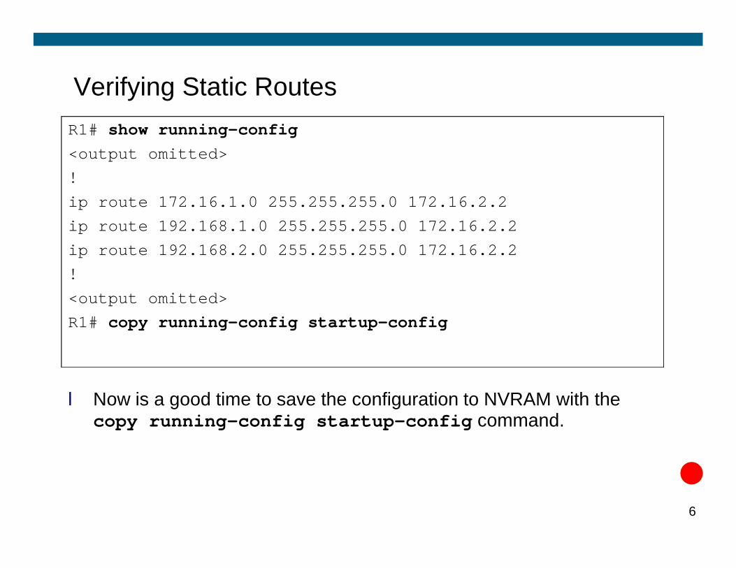
Verifying Static RoutesR1# show running-config<output omitted>!ip route 172.16.1.0 255.255.255.0 172.16.2.2ip route 192.168.1.0 255.255.255.0 172.16.2.2ip route 192.168.2.0 255.255.255.0 172.16.2.2!
l Now is a good time to save the configuration to NVRAM with the copy running-config startup-config command.
6
<output omitted>R1# copy running-config startup-config
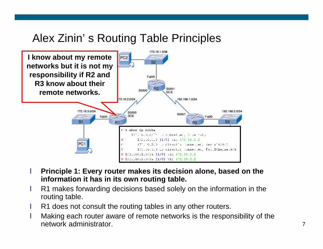
Alex Zinin’s Routing Table PrinciplesI know about my remote networks but it is not my responsibility if R2 and
R3 know about their remote networks.
l Principle 1: Every router makes its decision alone, based on the information it has in its own routing table.
l R1 makes forwarding decisions based solely on the information in the routing table.
l R1 does not consult the routing tables in any other routers. l Making each router aware of remote networks is the responsibility of the
network administrator. 7
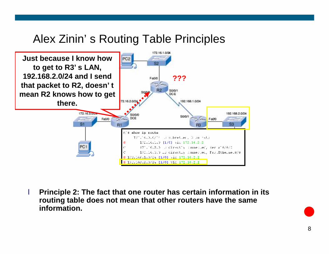
Alex Zinin’s Routing Table PrinciplesJust because I know how
to get to R3’s LAN, 192.168.2.0/24 and I send that packet to R2, doesn’t mean R2 knows how to get
there.
???
l Principle 2: The fact that one router has certain information in its routing table does not mean that other routers have the same information.
8
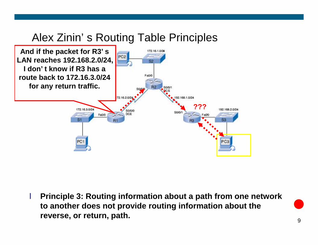
Alex Zinin’s Routing Table PrinciplesAnd if the packet for R3’s
LAN reaches 192.168.2.0/24, I don’t know if R3 has a
route back to 172.16.3.0/24 for any return traffic.
???
l Principle 3: Routing information about a path from one network to another does not provide routing information about the reverse, or return, path.
9
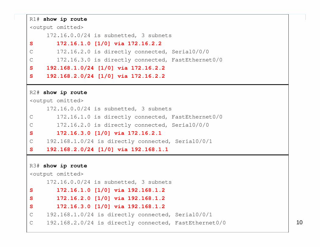
R1# show ip route<output omitted>
172.16.0.0/24 is subnetted, 3 subnetsS 172.16.1.0 [1/0] via 172.16.2.2C 172.16.2.0 is directly connected, Serial0/0/0C 172.16.3.0 is directly connected, FastEthernet0/0S 192.168.1.0/24 [1/0] via 172.16.2.2S 192.168.2.0/24 [1/0] via 172.16.2.2
R2# show ip route<output omitted>
172.16.0.0/24 is subnetted, 3 subnetsC 172.16.1.0 is directly connected, FastEthernet0/0C 172.16.2.0 is directly connected, Serial0/0/0
10
C 172.16.2.0 is directly connected, Serial0/0/0S 172.16.3.0 [1/0] via 172.16.2.1C 192.168.1.0/24 is directly connected, Serial0/0/1S 192.168.2.0/24 [1/0] via 192.168.1.1
R3# show ip route<output omitted>
172.16.0.0/24 is subnetted, 3 subnetsS 172.16.1.0 [1/0] via 192.168.1.2S 172.16.2.0 [1/0] via 192.168.1.2S 172.16.3.0 [1/0] via 192.168.1.2C 192.168.1.0/24 is directly connected, Serial0/0/1C 192.168.2.0/24 is directly connected, FastEthernet0/0
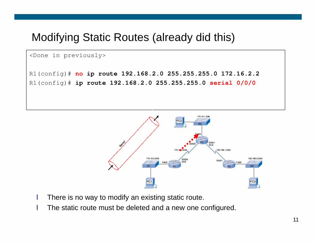
Modifying Static Routes (already did this)<Done in previously>
R1(config)# no ip route 192.168.2.0 255.255.255.0 172.16.2.2R1(config)# ip route 192.168.2.0 255.255.255.0 serial 0/0/0
l There is no way to modify an existing static route. l The static route must be deleted and a new one configured.
11
Summary and Default Static Routesl Summary Static Routesl Default Static Routes
12
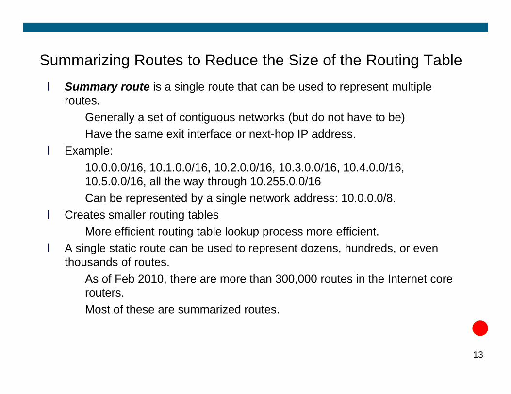
Summarizing Routes to Reduce the Size of the Routing Tablel Summary route is a single route that can be used to represent multiple
routes. ü Generally a set of contiguous networks (but do not have to be) ü Have the same exit interface or next-hop IP address.
l Example:ü 10.0.0.0/16, 10.1.0.0/16, 10.2.0.0/16, 10.3.0.0/16, 10.4.0.0/16,
10.5.0.0/16, all the way through 10.255.0.0/16 ü Can be represented by a single network address: 10.0.0.0/8.ü Can be represented by a single network address: 10.0.0.0/8.
l Creates smaller routing tablesü More efficient routing table lookup process more efficient.
l A single static route can be used to represent dozens, hundreds, or even thousands of routes.ü As of Feb 2010, there are more than 300,000 routes in the Internet core
routers. ü Most of these are summarized routes.
13
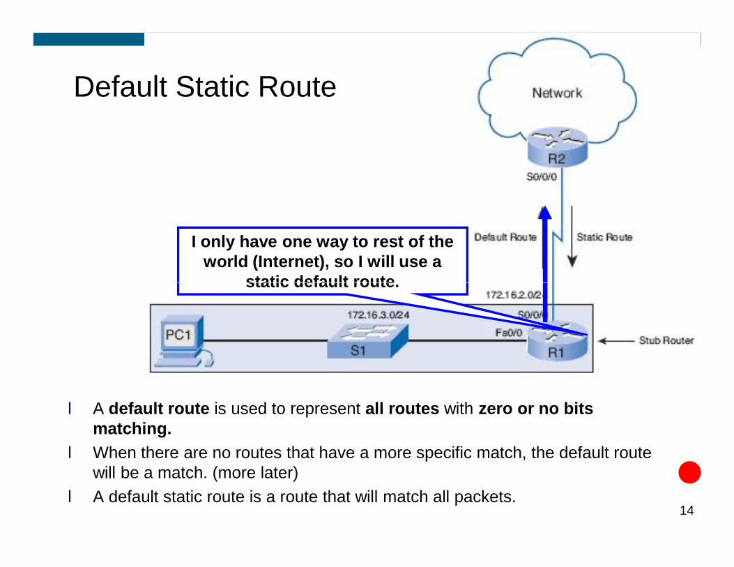
I only have one way to rest of the world (Internet), so I will use a
static default route.
Default Static Route
l A default route is used to represent all routes with zero or no bits matching.
l When there are no routes that have a more specific match, the default route will be a match. (more later)
l A default static route is a route that will match all packets. 14
static default route.
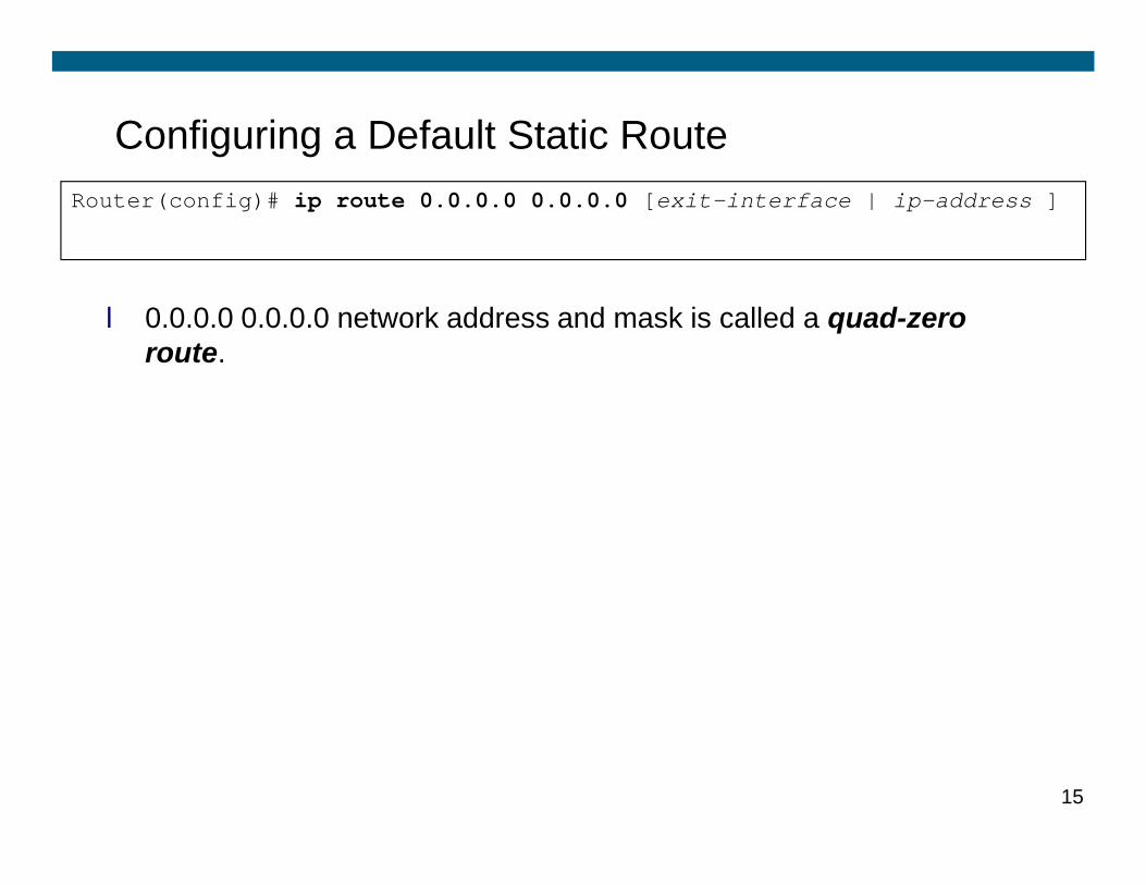
Configuring a Default Static Route
l 0.0.0.0 0.0.0.0 network address and mask is called a quad-zero route.
Router(config)# ip route 0.0.0.0 0.0.0.0 [exit-interface | ip-address ]
15
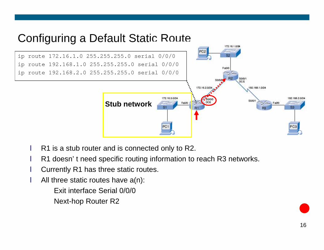
Configuring a Default Static Routeip route 172.16.1.0 255.255.255.0 serial 0/0/0ip route 192.168.1.0 255.255.255.0 serial 0/0/0ip route 192.168.2.0 255.255.255.0 serial 0/0/0
Stub network
l R1 is a stub router and is connected only to R2. l R1 doesn’t need specific routing information to reach R3 networks. l Currently R1 has three static routes. l All three static routes have a(n):ü Exit interface Serial 0/0/0 ü Next-hop Router R2
16
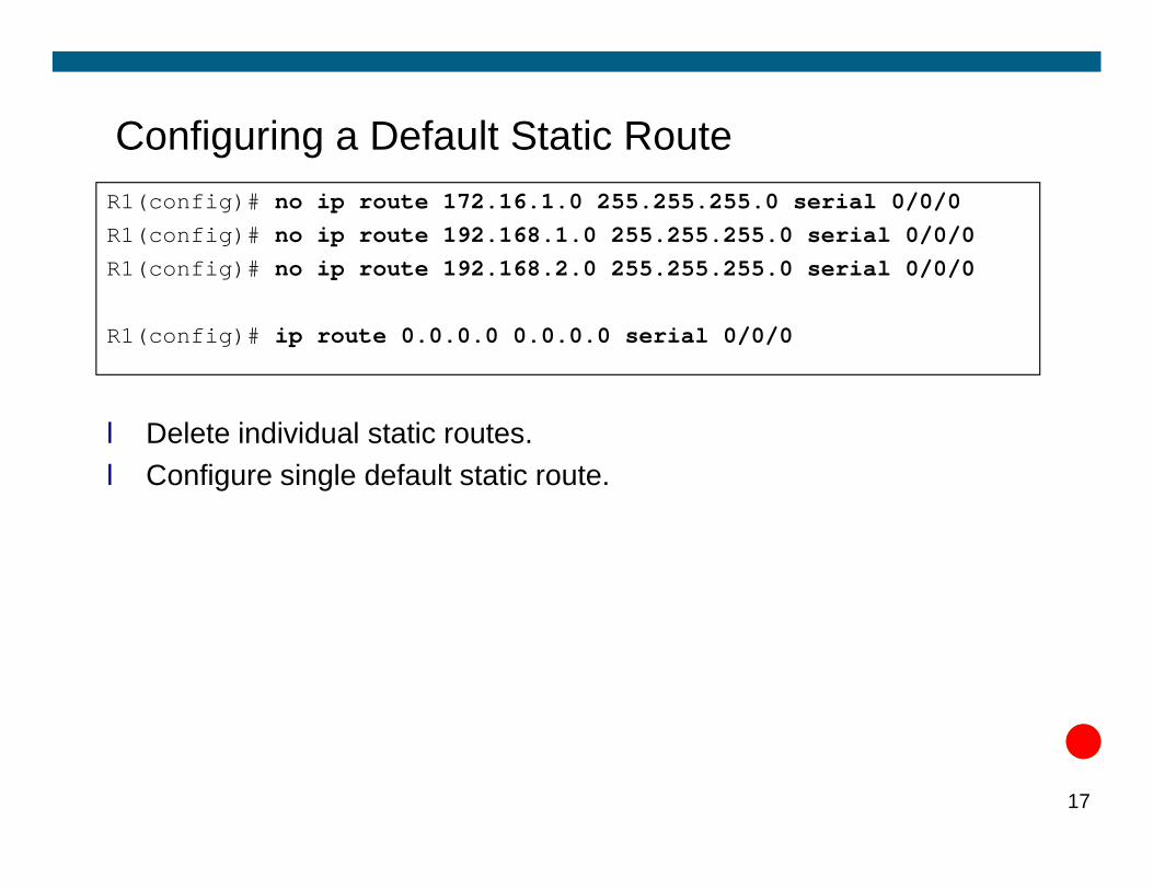
Configuring a Default Static Route
l Delete individual static routes.
R1(config)# no ip route 172.16.1.0 255.255.255.0 serial 0/0/0R1(config)# no ip route 192.168.1.0 255.255.255.0 serial 0/0/0R1(config)# no ip route 192.168.2.0 255.255.255.0 serial 0/0/0
R1(config)# ip route 0.0.0.0 0.0.0.0 serial 0/0/0
l Delete individual static routes.l Configure single default static route.
17
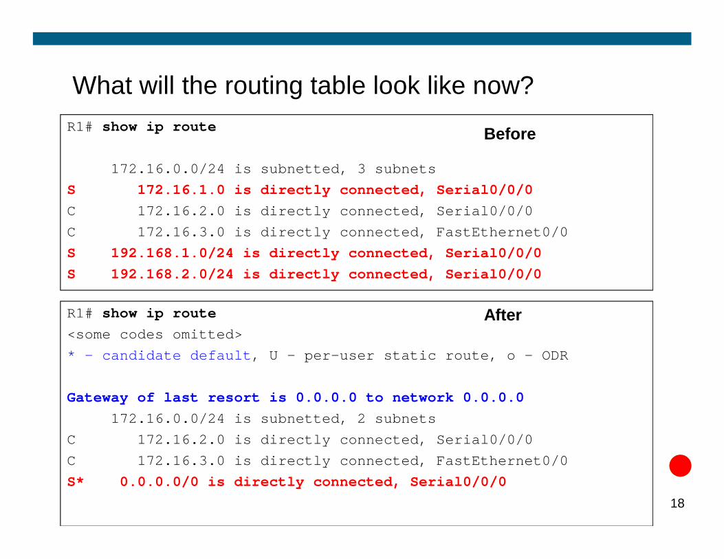
What will the routing table look like now?R1# show ip route
172.16.0.0/24 is subnetted, 3 subnetsS 172.16.1.0 is directly connected, Serial0/0/0C 172.16.2.0 is directly connected, Serial0/0/0C 172.16.3.0 is directly connected, FastEthernet0/0S 192.168.1.0/24 is directly connected, Serial0/0/0S 192.168.2.0/24 is directly connected, Serial0/0/0
Before
18
S 192.168.2.0/24 is directly connected, Serial0/0/0
R1# show ip route<some codes omitted>* - candidate default, U - per-user static route, o - ODR
Gateway of last resort is 0.0.0.0 to network 0.0.0.0172.16.0.0/24 is subnetted, 2 subnets
C 172.16.2.0 is directly connected, Serial0/0/0C 172.16.3.0 is directly connected, FastEthernet0/0S* 0.0.0.0/0 is directly connected, Serial0/0/0
After
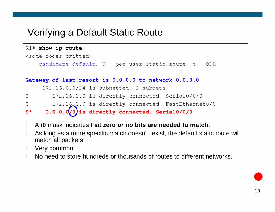
Verifying a Default Static RouteR1# show ip route<some codes omitted>* - candidate default, U - per-user static route, o - ODR
Gateway of last resort is 0.0.0.0 to network 0.0.0.0172.16.0.0/24 is subnetted, 2 subnets
C 172.16.2.0 is directly connected, Serial0/0/0C 172.16.3.0 is directly connected, FastEthernet0/0
l A /0 mask indicates that zero or no bits are needed to match. l As long as a more specific match doesn’t exist, the default static route will
match all packets.l Very commonl No need to store hundreds or thousands of routes to different networks.
19
C 172.16.3.0 is directly connected, FastEthernet0/0S* 0.0.0.0/0 is directly connected, Serial0/0/0
Troubleshooting a Missing Route
l When end-to-end connectivity is a problem, begin by making sure that you can ping your own interface and other devices on your own directly connected networks.
l When this has been verified, begin testing connectivity to remote networks and from other devices.
l Networks are subject to many different forces that can cause their status to change quite often:status to change quite often:ü Interface failureü Dropped connection by a service providerü Oversaturation of linksü Incorrect configuration entered by an administrator.
l Tools:ü pingü tracerouteü show ip routeü show ip interface brief 20
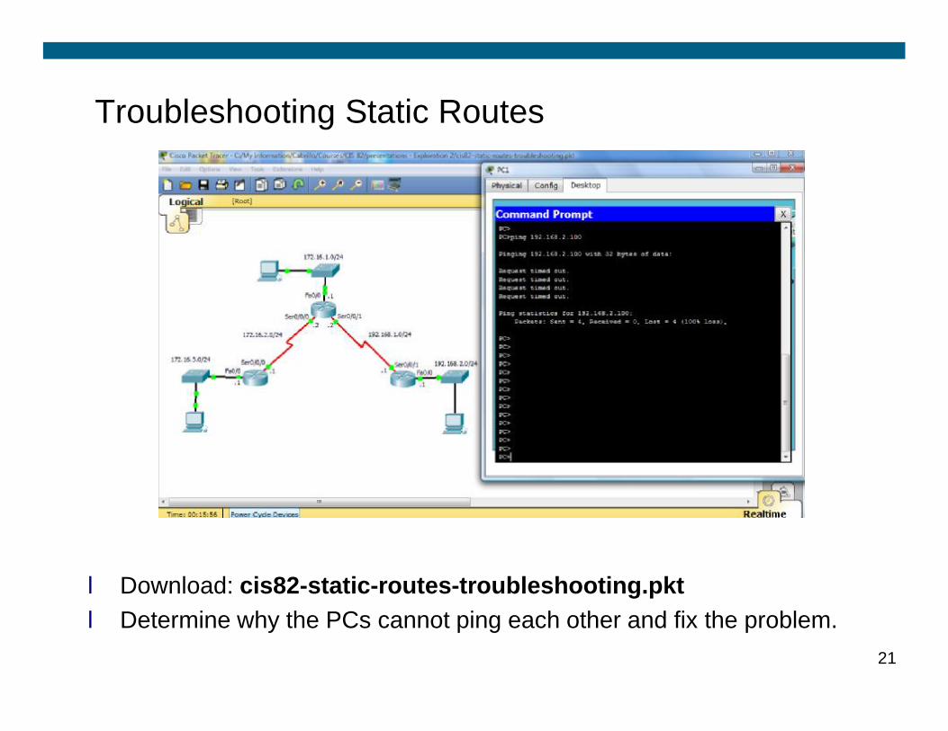
Troubleshooting Static Routes
l Download: cis82-static-routes-troubleshooting.pktl Determine why the PCs cannot ping each other and fix the problem.
21

Troubleshooting Techniques
l Make sure all interfaces are “up” and “up”
l What command will help you determine this?l What command will help you determine this?ü R1# show ip interface brief
l What are some of the reasons an interface may be down?ü Didn’t issue the “no shutdown” commandü Missing “clock rate” command on Serial DCE interface.ü Missing or incorrect cableü No connection to other end device:ü Ethernet: No switch or hub attachedü Serial: Other end not connected or configuredü Both ends of serial interface must be configured correctly to be
“up”22
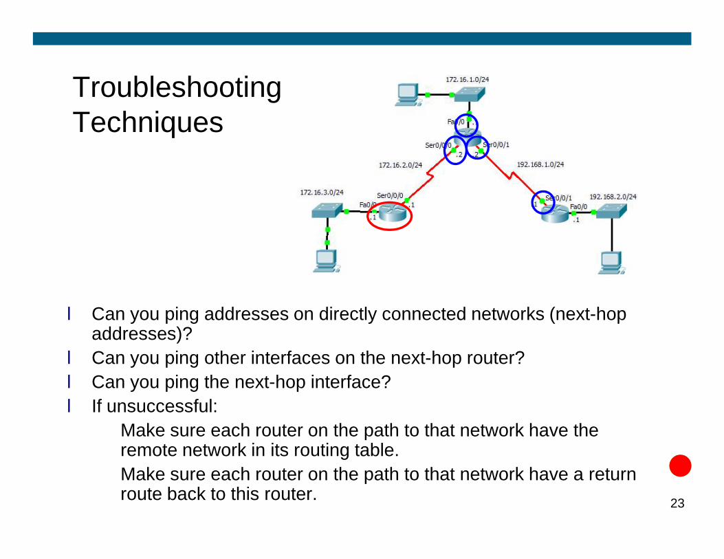
Troubleshooting Techniques
l Can you ping addresses on directly connected networks (next-hop addresses)?
l Can you ping other interfaces on the next-hop router?l Can you ping the next-hop interface?l If unsuccessful:ü Make sure each router on the path to that network have the
remote network in its routing table.ü Make sure each router on the path to that network have a return
route back to this router. 23

Access Control Lists
© 2006 Cisco Systems, Inc. All rights reserved. Cisco PublicITE I Chapter 6 1
Overview
§ Routers provide basic traffic filtering capabilities, such as blocking Internet traffic, with access control lists (ACLs).§ An ACL is a sequential list of permit or deny statements that apply to
addresses or upper-layer protocols.
§ This module will introduce standard and extended ACLs as a means
2
§ This module will introduce standard and extended ACLs as a means to control network traffic, and how ACLs are used as part of a security solution.
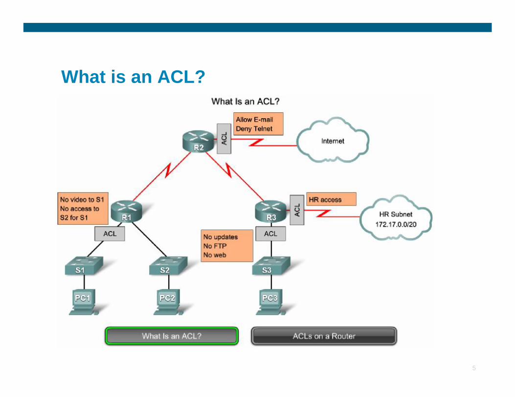
What is an ACL?
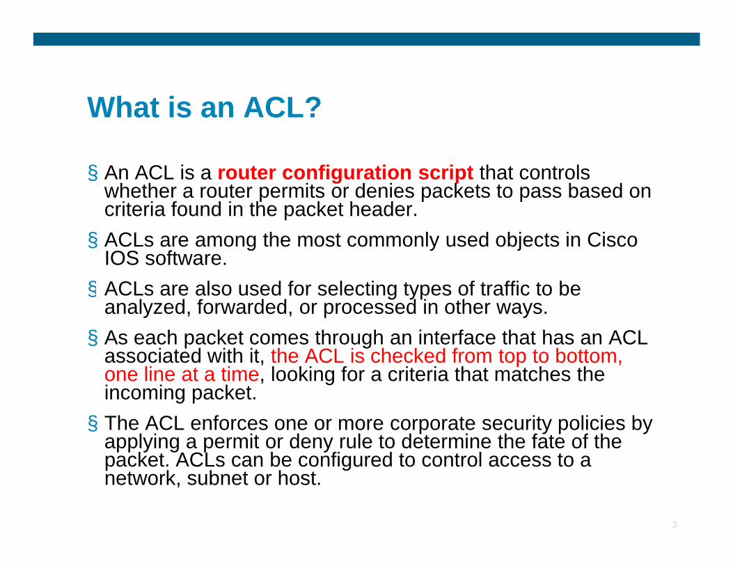
§ An ACL is a router configuration script that controls whether a router permits or denies packets to pass based on criteria found in the packet header. § ACLs are among the most commonly used objects in Cisco
IOS software.§ ACLs are also used for selecting types of traffic to be
3
§ ACLs are also used for selecting types of traffic to be analyzed, forwarded, or processed in other ways. § As each packet comes through an interface that has an ACL
associated with it, the ACL is checked from top to bottom, one line at a time, looking for a criteria that matches the incoming packet. § The ACL enforces one or more corporate security policies by
applying a permit or deny rule to determine the fate of the packet. ACLs can be configured to control access to a network, subnet or host.
ACL Guidelines
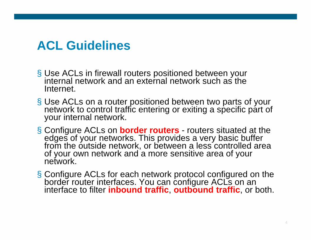
§ Use ACLs in firewall routers positioned between your internal network and an external network such as the Internet. § Use ACLs on a router positioned between two parts of your
network to control traffic entering or exiting a specific part of your internal network.
4
your internal network. § Configure ACLs on border routers - routers situated at the
edges of your networks. This provides a very basic buffer from the outside network, or between a less controlled area of your own network and a more sensitive area of your network. § Configure ACLs for each network protocol configured on the
border router interfaces. You can configure ACLs on an interface to filter inbound traffic, outbound traffic, or both.
What is an ACL?
5
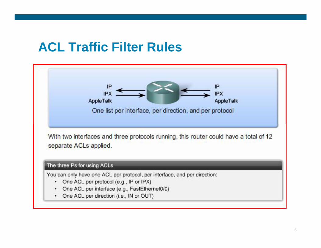
ACL Traffic Filter Rules
6
Types of ACLs
§ There are two types of ACLsStandard: permit or deny packets based on source IP
Extended: filter packets based on multiple
7
Extended: filter packets based on multiple criteria like source and destination IP, source and destination ports, and more.
Standard ACL Example
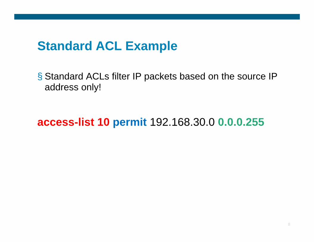
§ Standard ACLs filter IP packets based on the source IP address only!
access-list 10 permit 192.168.30.0 0.0.0.255
8
access-list 10 permit 192.168.30.0 0.0.0.255
Extended ACLs
§ Extended ACLs are used more often than standard ACLs because they provide a greater range of control.§ Like standard ACLs, extended ACLs check the source
packet addresses, but they also check the destination address, protocols and port numbers (or services).
9
address, protocols and port numbers (or services).§ This gives a greater range of criteria on which to base
the ACL. § For example, an extended ACL can simultaneously
allow e-mail traffic from a network to a specific destination while denying file transfers and web browsing.
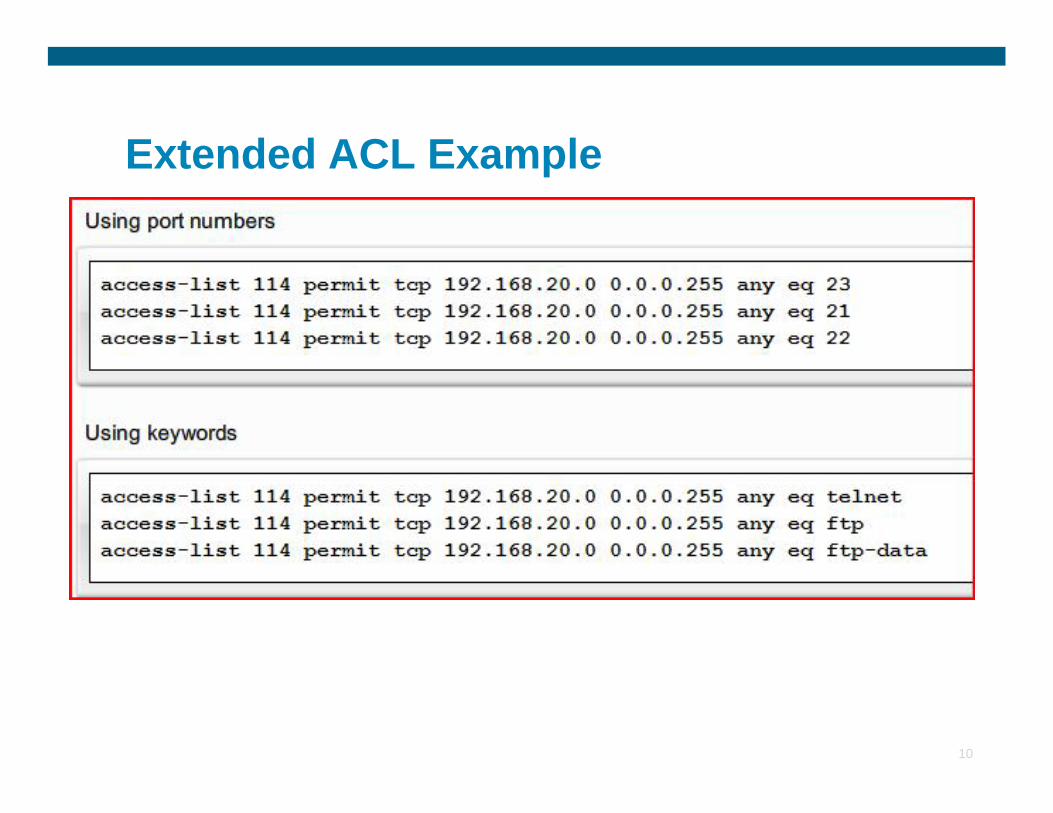
Extended ACL Example
10
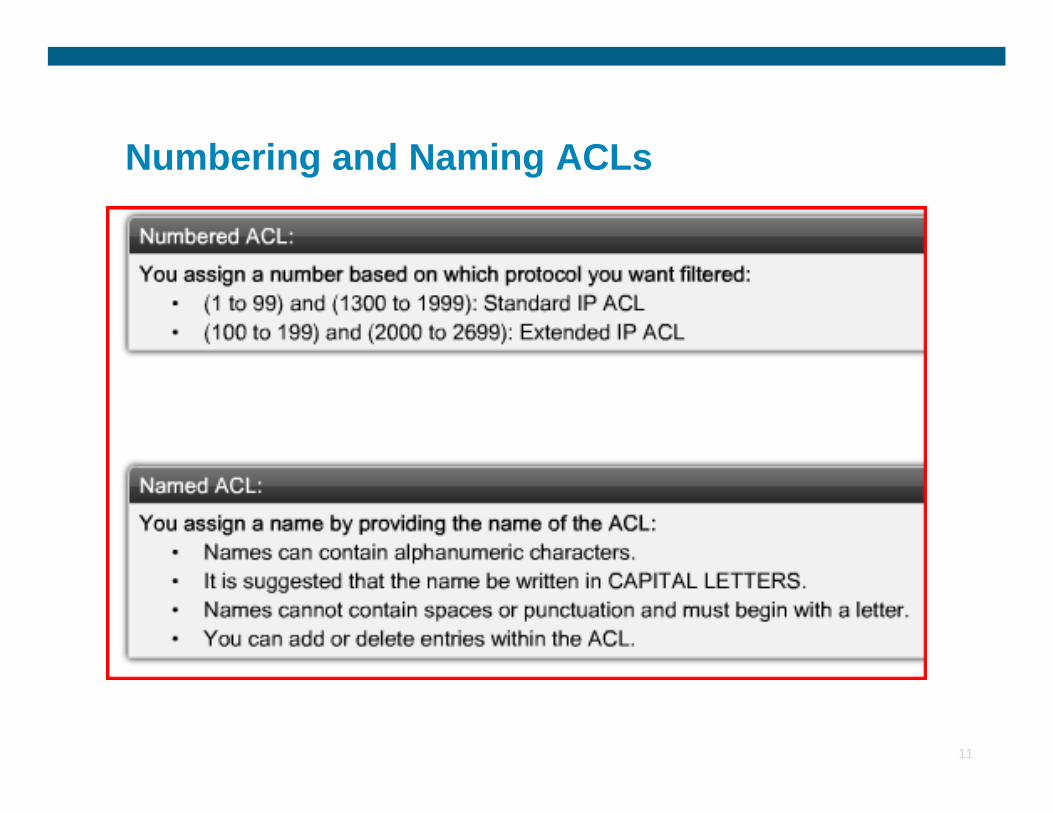
Numbering and Naming ACLs
11
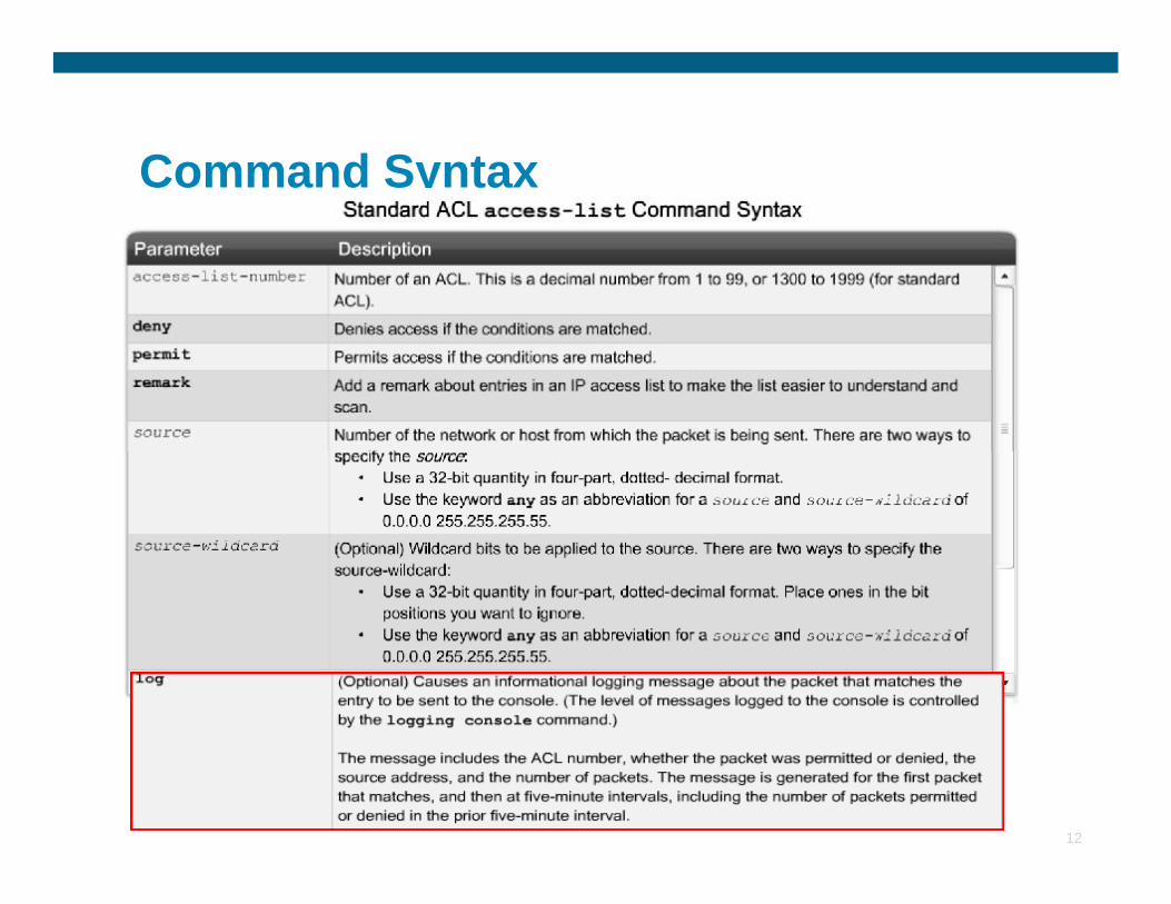
Command Syntax
12
Wildcard Mask
§ A wildcard mask is a string of binary digits telling a router which part of an IP address to look at.
§ A wildcard mask is a mask of bits that indicates which parts of an IP address can assume any value.
13
•Used by routing protocols to define the networks or subnets to be advertised
•Used by Access Control Lists (ACLs) to define addresses or address ranges
• It allows to filter out individual addresses, subnets, or ranges of addresses (also allows to filter on odd and even numbers).
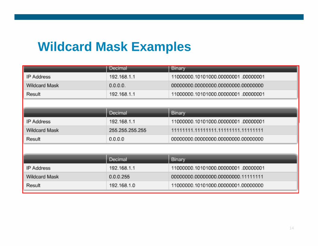
Wildcard Mask Examples
14
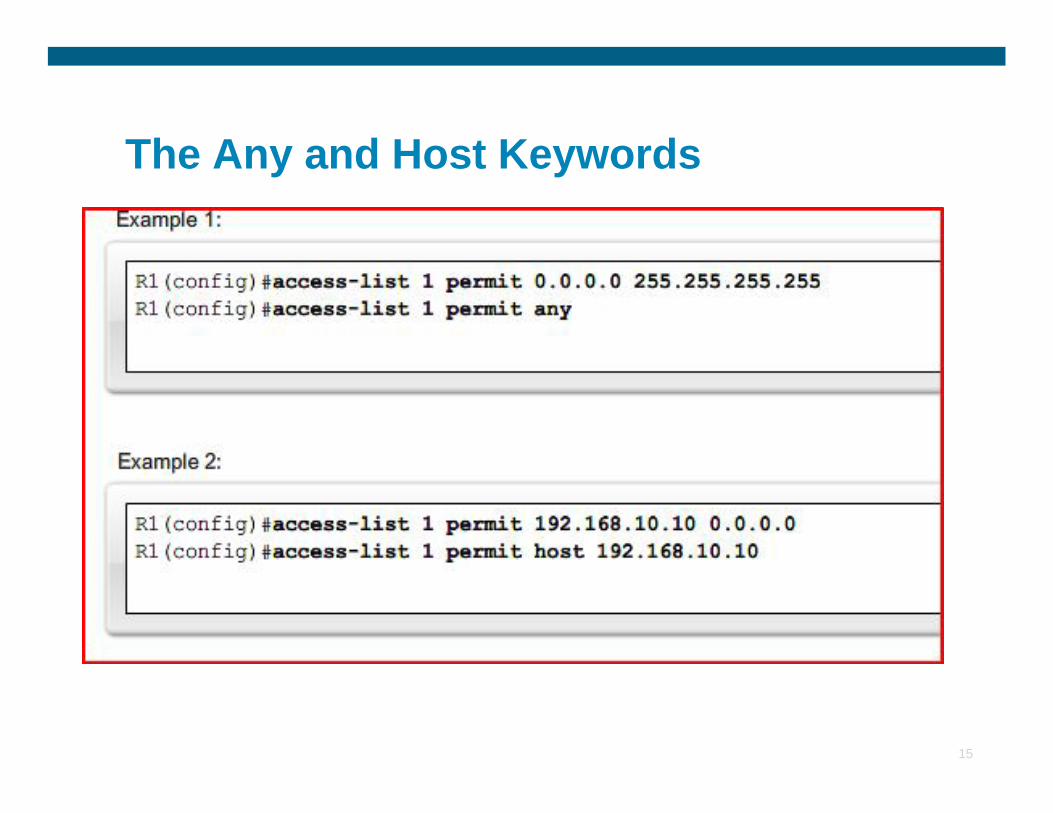
The Any and Host Keywords
15
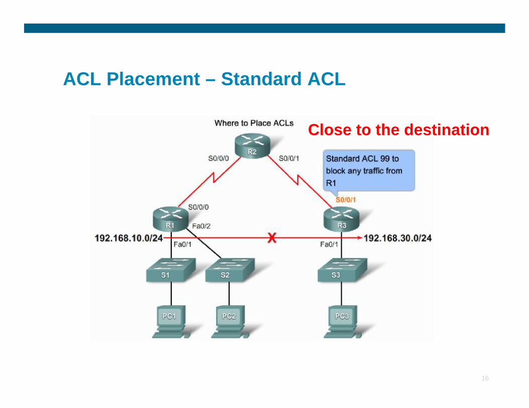
ACL Placement – Standard ACL
Close to the destination
16
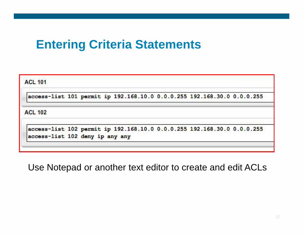
Entering Criteria Statements
17
Use Notepad or another text editor to create and edit ACLs
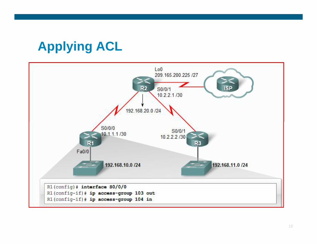
Applying ACL
18
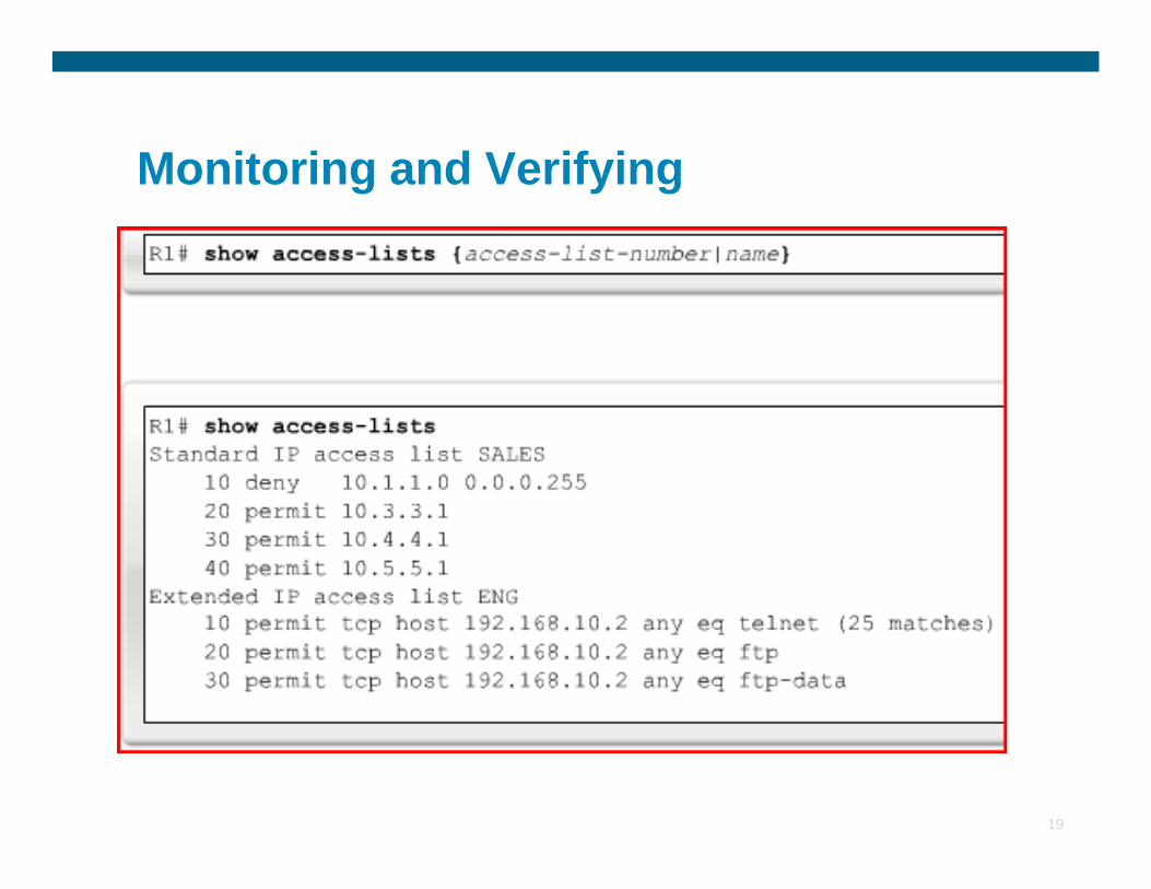
Monitoring and Verifying
19
Examples
20
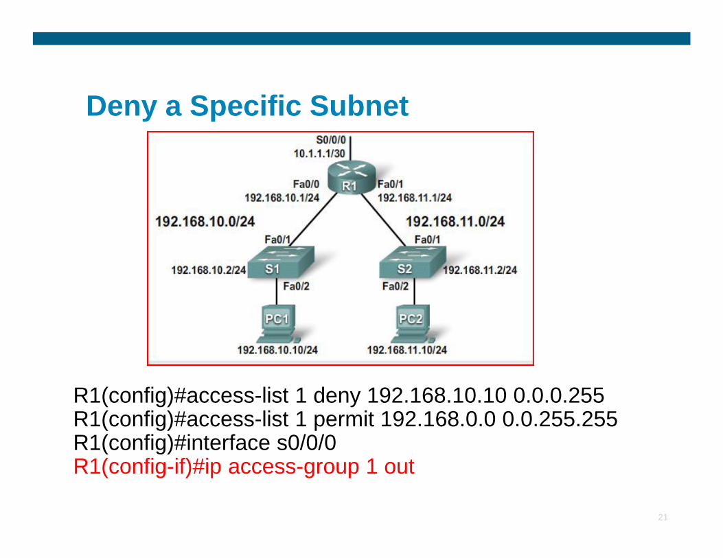
Deny a Specific Subnet
21
R1(config)#access-list 1 deny 192.168.10.10 0.0.0.255R1(config)#access-list 1 permit 192.168.0.0 0.0.255.255R1(config)#interface s0/0/0R1(config-if)#ip access-group 1 out
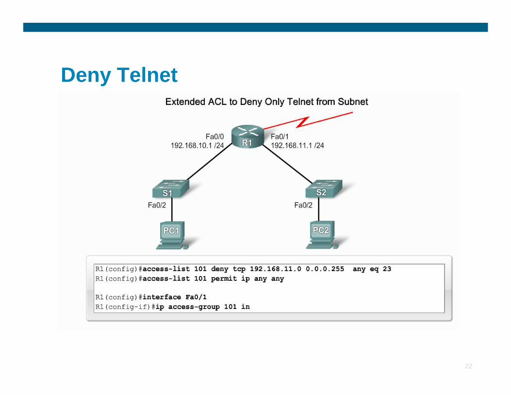
Deny Telnet
22
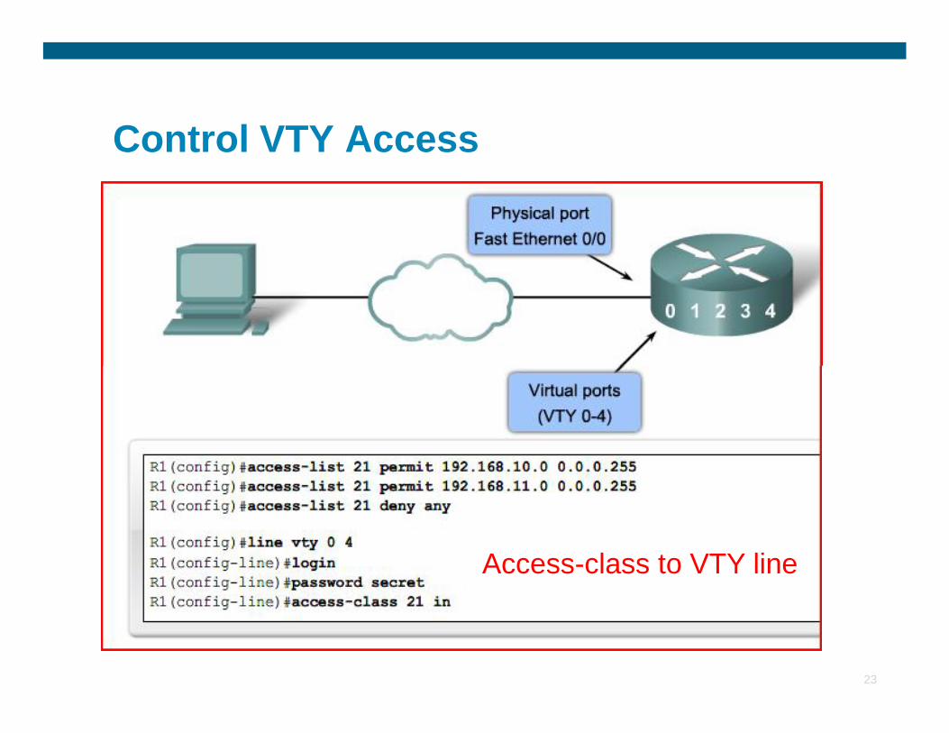
Control VTY Access
23
Access-class to VTY line
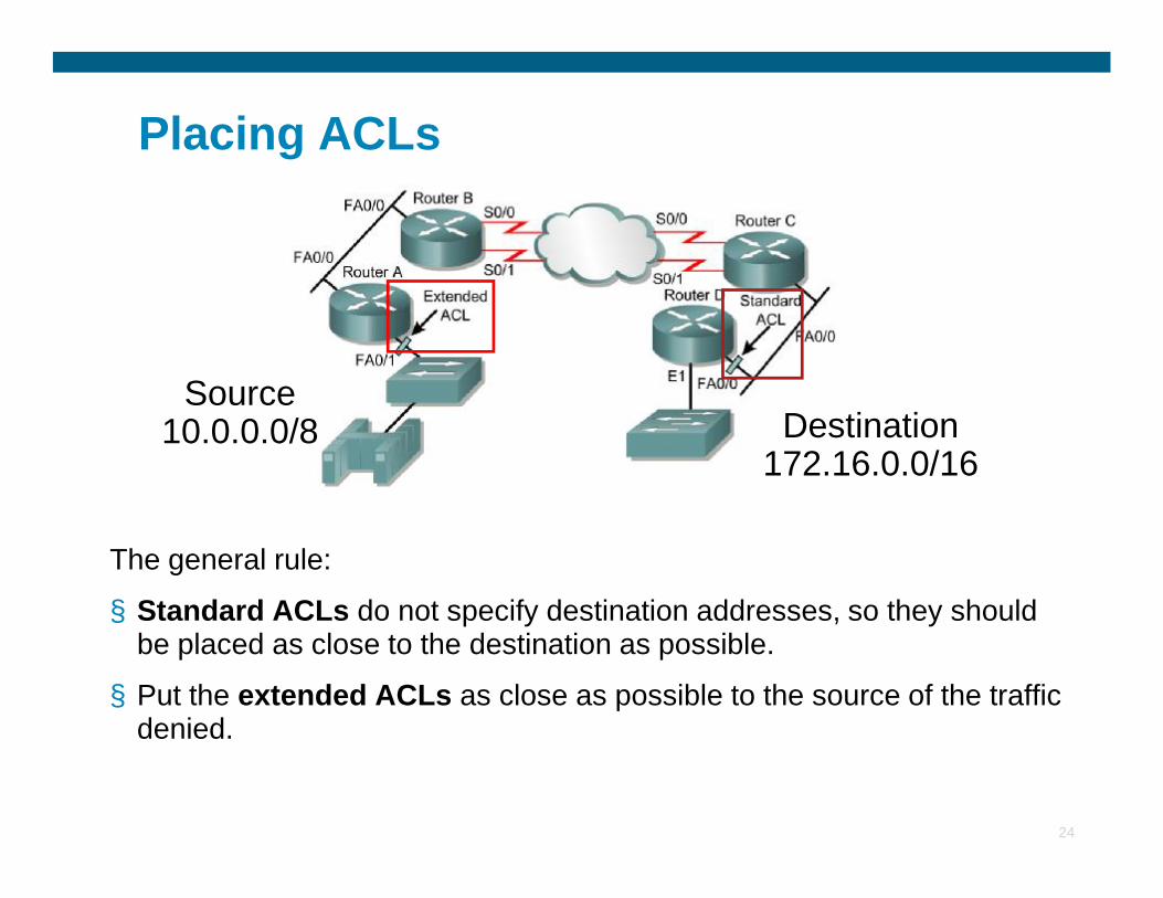
Placing ACLs
Source 10.0.0.0/8 Destination
172.16.0.0/16
24
The general rule:
§ Standard ACLs do not specify destination addresses, so they should be placed as close to the destination as possible.
§ Put the extended ACLs as close as possible to the source of the traffic denied.
10.0.0.0/8172.16.0.0/16
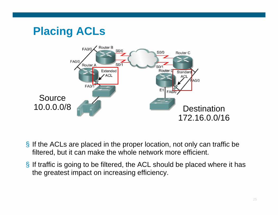
Placing ACLs
Source 10.0.0.0/8 Destination
25
§ If the ACLs are placed in the proper location, not only can traffic be filtered, but it can make the whole network more efficient.
§ If traffic is going to be filtered, the ACL should be placed where it has the greatest impact on increasing efficiency.
10.0.0.0/8 Destination 172.16.0.0/16
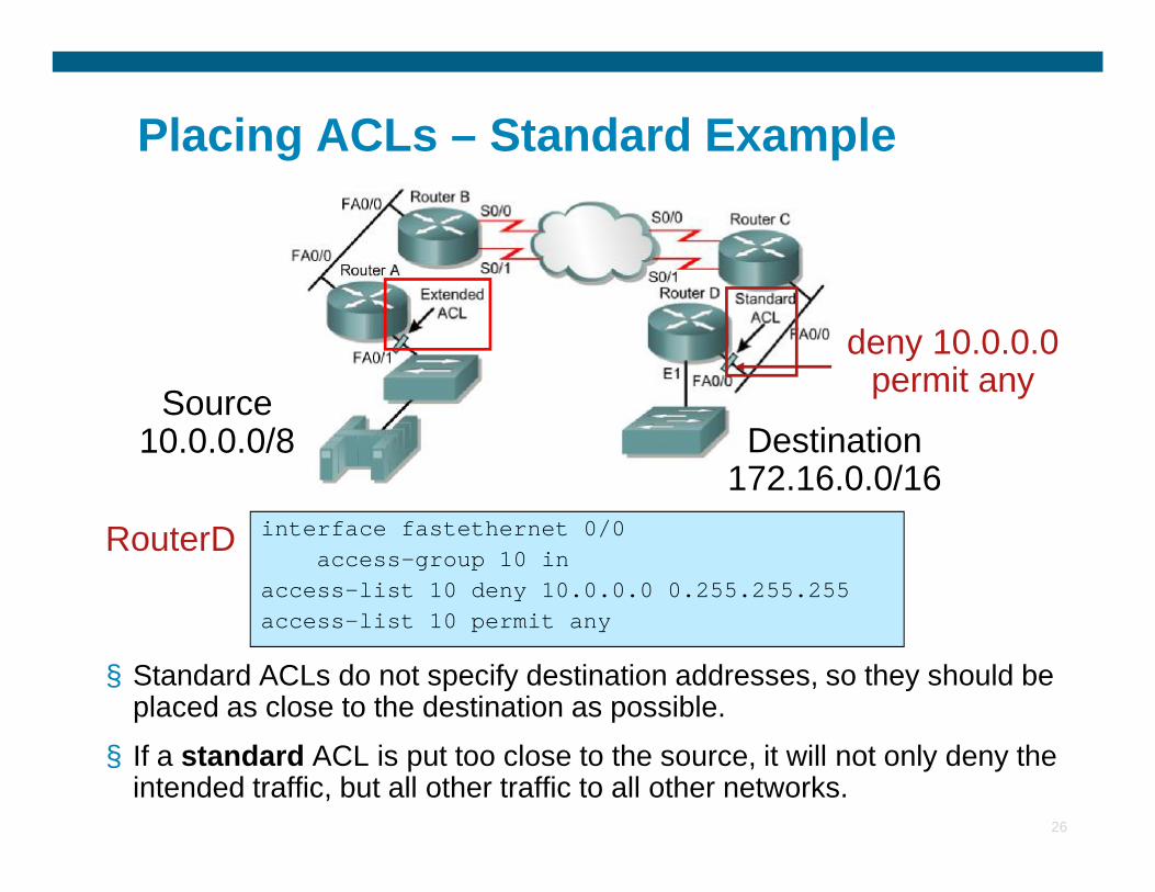
Placing ACLs – Standard Example
Source 10.0.0.0/8 Destination
deny 10.0.0.0 permit any
26
§ Standard ACLs do not specify destination addresses, so they should be placed as close to the destination as possible.
§ If a standard ACL is put too close to the source, it will not only deny the intended traffic, but all other traffic to all other networks.
10.0.0.0/8 Destination 172.16.0.0/16
interface fastethernet 0/0access-group 10 in
access-list 10 deny 10.0.0.0 0.255.255.255access-list 10 permit any
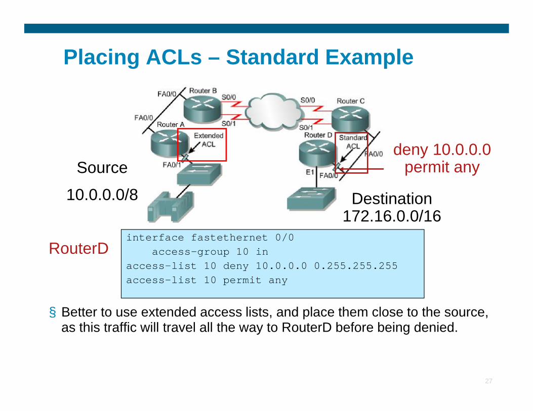
RouterD
Placing ACLs – Standard Example
Source
10.0.0.0/8
deny 10.0.0.0 permit any
Destination
27
§ Better to use extended access lists, and place them close to the source, as this traffic will travel all the way to RouterD before being denied.
interface fastethernet 0/0access-group 10 in
access-list 10 deny 10.0.0.0 0.255.255.255access-list 10 permit any
RouterD
Destination 172.16.0.0/16
Placing ACLs – Extended Example
deny telnet deny ftp
permit any
Source 10.0.0.0/8 Destination
28
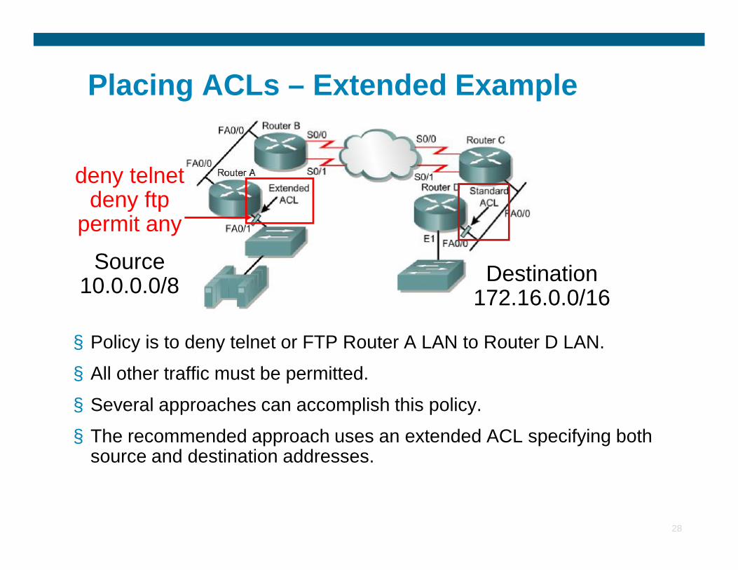
§ Policy is to deny telnet or FTP Router A LAN to Router D LAN.
§ All other traffic must be permitted.
§ Several approaches can accomplish this policy.
§ The recommended approach uses an extended ACL specifying both source and destination addresses.
10.0.0.0/8 Destination 172.16.0.0/16
Placing ACLs – Extended Example
deny telnet deny ftp
permit anySource
10.0.0.0/8 Destination 172.16.0.0/16
29
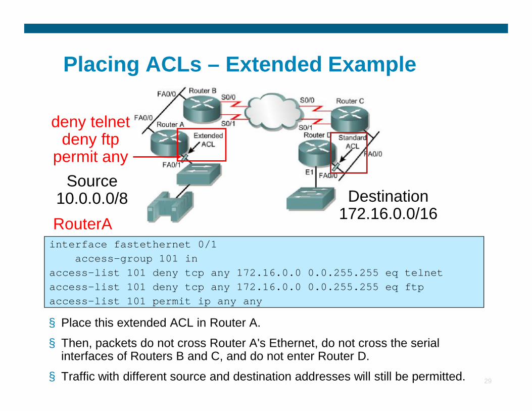
§ Place this extended ACL in Router A.
§ Then, packets do not cross Router A's Ethernet, do not cross the serial interfaces of Routers B and C, and do not enter Router D.
§ Traffic with different source and destination addresses will still be permitted.
interface fastethernet 0/1access-group 101 in
access-list 101 deny tcp any 172.16.0.0 0.0.255.255 eq telnet access-list 101 deny tcp any 172.16.0.0 0.0.255.255 eq ftpaccess-list 101 permit ip any any
RouterA10.0.0.0/8
172.16.0.0/16
Placing ACLs – Extended Example
deny telnet deny ftp
permit anySource
10.0.0.0/8 Destination 172.16.0.0/16
30
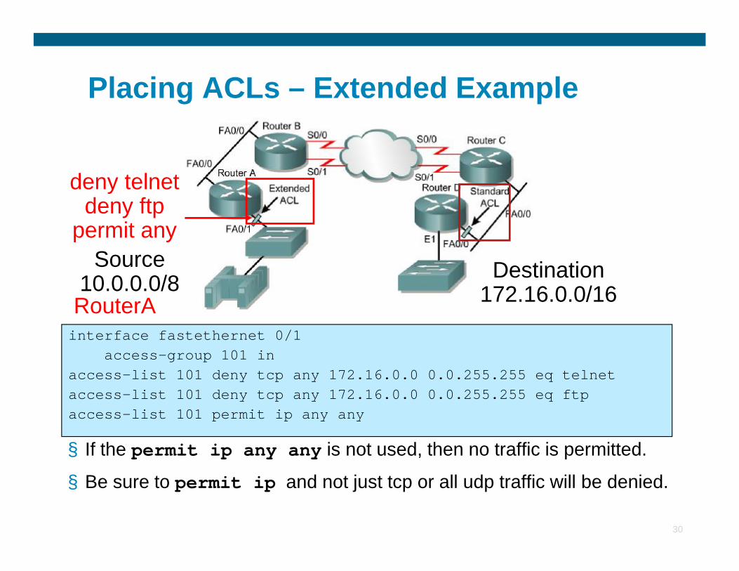
§ If the permit ip any any is not used, then no traffic is permitted.
§ Be sure to permit ip and not just tcp or all udp traffic will be denied.
interface fastethernet 0/1access-group 101 in
access-list 101 deny tcp any 172.16.0.0 0.0.255.255 eq telnet access-list 101 deny tcp any 172.16.0.0 0.0.255.255 eq ftpaccess-list 101 permit ip any any
RouterA10.0.0.0/8 172.16.0.0/16
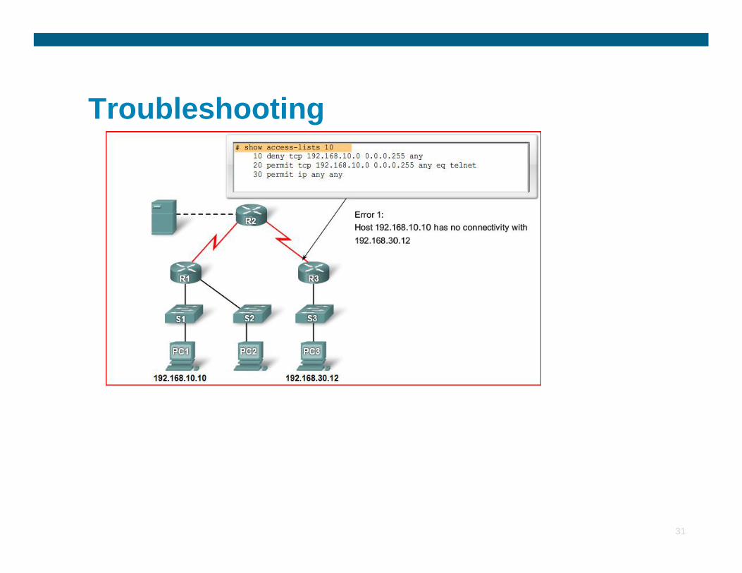
Troubleshooting
31
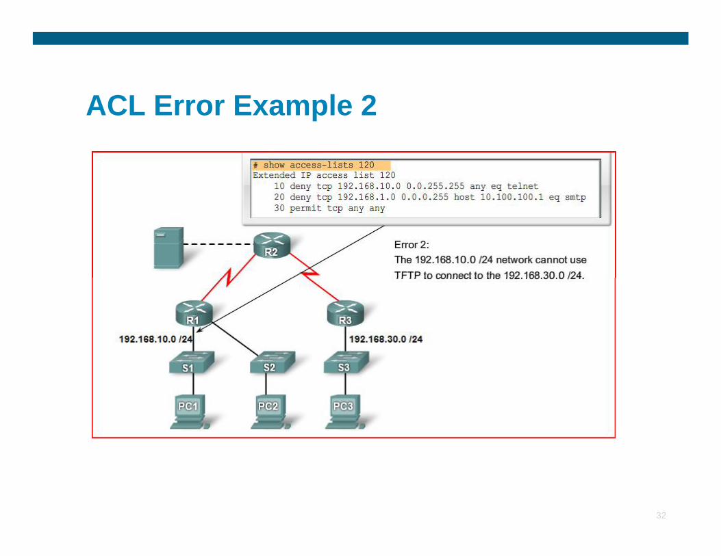
ACL Error Example 2
32
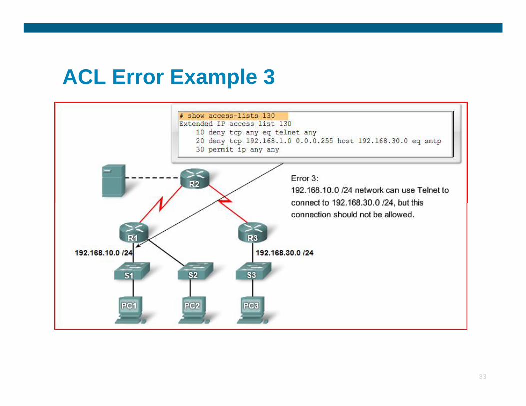
ACL Error Example 3
33
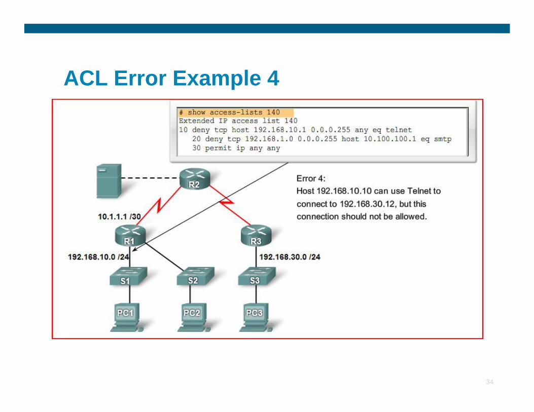
ACL Error Example 4
34
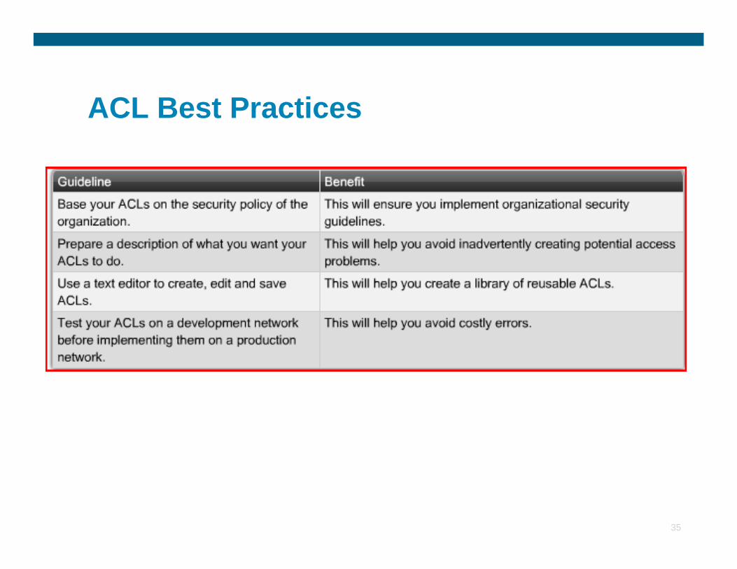
ACL Best Practices
35
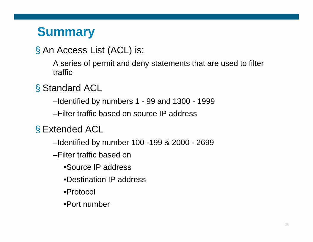
Summary§ An Access List (ACL) is:
A series of permit and deny statements that are used to filter traffic
§ Standard ACL–Identified by numbers 1 - 99 and 1300 - 1999–Filter traffic based on source IP address
36
§ Extended ACL–Identified by number 100 -199 & 2000 - 2699–Filter traffic based on
•Source IP address•Destination IP address•Protocol•Port number
Summary
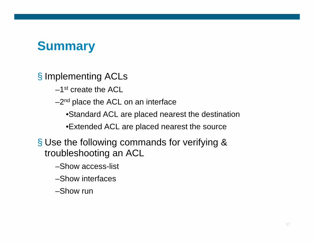
§ Implementing ACLs–1st create the ACL–2nd place the ACL on an interface
•Standard ACL are placed nearest the destination
37
•Extended ACL are placed nearest the source
§ Use the following commands for verifying & troubleshooting an ACL
–Show access-list–Show interfaces–Show run

38

DMZ
1
What is a DMZ?
§ DMZ stands for demilitarized zone.
§ In addition to the standard inside (private) and outside (public) zones, firewalls can have one or more DMZ zones.
2
§ Although it usually involves a firewall, A firewall is not required to create a DMZ. It can be created between two routers using ACL’s.
What is a DMZ?
§ A DMZ is a network that is neither inside nor outside the firewall.
§ This network can be accessed from inside and outsidethe firewall, but security rules (ACL’s) will stop traffic in the DMZ from connecting to devices on the inside. A
3
the DMZ from connecting to devices on the inside. A DMZ is less secure than the inside network, but more secure than the outside network.
§ Servers in a DMZ should be secured as if they were on the Internet. Firewall rules should permit only the required services to each server.
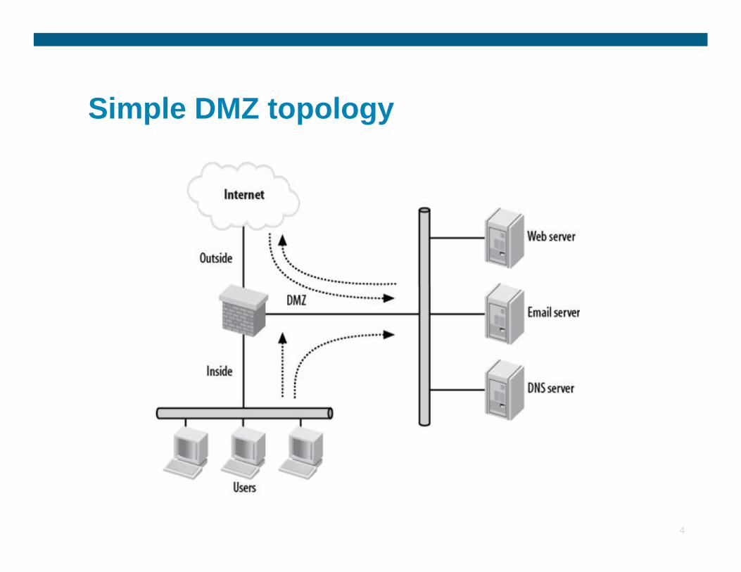
Simple DMZ topology
4
DMZ Features
§ The main benefit of a DMZ is isolation. If a DMZ server gets attacked and is compromised, the attacker will not have access to the users on the inside network. However, the attacker will have access to the other servers in the DMZ as they are on the same network.
5
servers in the DMZ as they are on the same network.
§ The servers can be protected form this by implementing other Cisco security features such as private VLAN’s, port ACL’s, and multiple DMZ’s.

6

Packet Tracer – Complex Networks with Static Routes Configuration
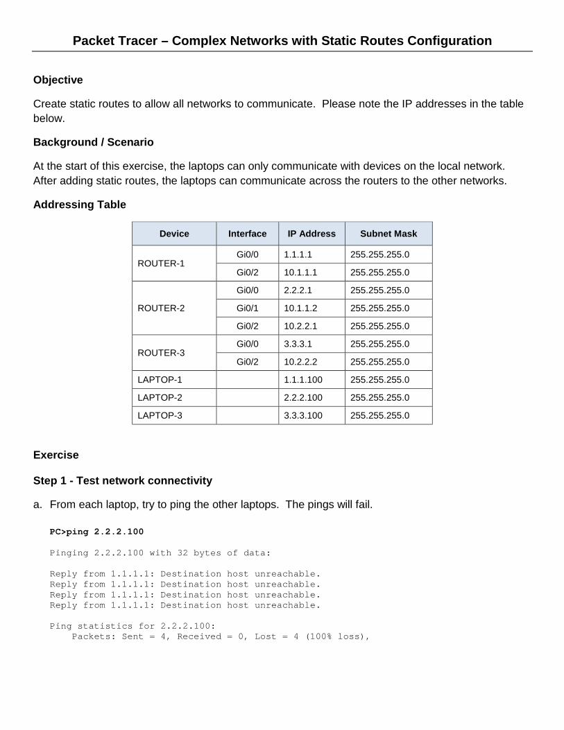
Objective
Create static routes to allow all networks to communicate. Please note the IP addresses in the table below.
Background / Scenario
At the start of this exercise, the laptops can only communicate with devices on the local network. After adding static routes, the laptops can communicate across the routers to the other networks.
Addressing Table
Device Interface IP Address Subnet Mask
ROUTER-1 Gi0/0 1.1.1.1 255.255.255.0
Gi0/2 10.1.1.1 255.255.255.0
ROUTER-2
Gi0/0 2.2.2.1 255.255.255.0
Gi0/1 10.1.1.2 255.255.255.0
Gi0/2 10.2.2.1 255.255.255.0
ROUTER-3 Gi0/0 3.3.3.1 255.255.255.0
Gi0/2 10.2.2.2 255.255.255.0
LAPTOP-1 1.1.1.100 255.255.255.0
LAPTOP-2 2.2.2.100 255.255.255.0
LAPTOP-3 3.3.3.100 255.255.255.0
Exercise
Step 1 - Test network connectivity
a. From each laptop, try to ping the other laptops. The pings will fail.
PC>ping 2.2.2.100 Pinging 2.2.2.100 with 32 bytes of data: Reply from 1.1.1.1: Destination host unreachable. Reply from 1.1.1.1: Destination host unreachable. Reply from 1.1.1.1: Destination host unreachable. Reply from 1.1.1.1: Destination host unreachable. Ping statistics for 2.2.2.100: Packets: Sent = 4, Received = 0, Lost = 4 (100% loss),
Packet Tracer – Complex Networks with Static Routes Configuration
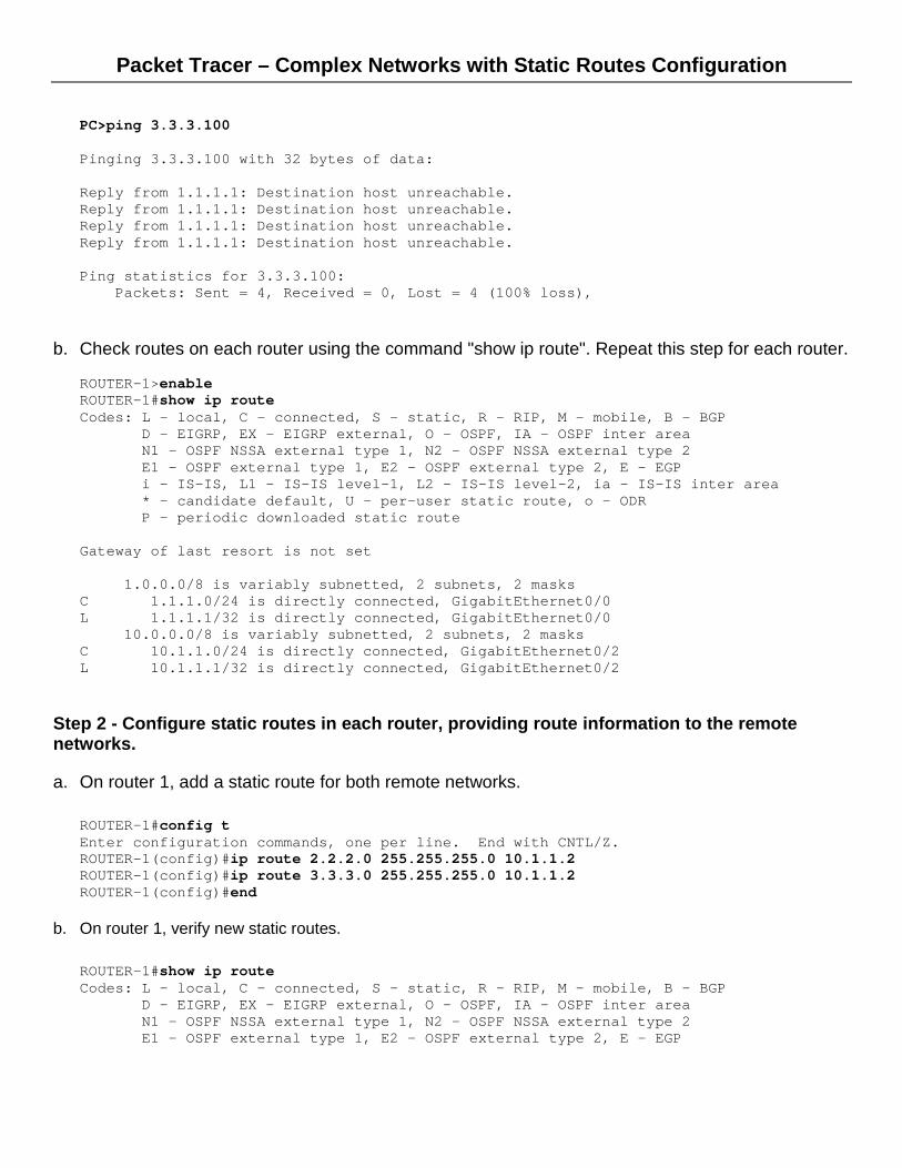
PC>ping 3.3.3.100 Pinging 3.3.3.100 with 32 bytes of data: Reply from 1.1.1.1: Destination host unreachable. Reply from 1.1.1.1: Destination host unreachable. Reply from 1.1.1.1: Destination host unreachable. Reply from 1.1.1.1: Destination host unreachable. Ping statistics for 3.3.3.100: Packets: Sent = 4, Received = 0, Lost = 4 (100% loss),
b. Check routes on each router using the command "show ip route". Repeat this step for each router.
ROUTER-1>enable ROUTER-1#show ip route Codes: L - local, C - connected, S - static, R - RIP, M - mobile, B - BGP D - EIGRP, EX - EIGRP external, O - OSPF, IA - OSPF inter area N1 - OSPF NSSA external type 1, N2 - OSPF NSSA external type 2 E1 - OSPF external type 1, E2 - OSPF external type 2, E - EGP i - IS-IS, L1 - IS-IS level-1, L2 - IS-IS level-2, ia - IS-IS inter area * - candidate default, U - per-user static route, o - ODR P - periodic downloaded static route Gateway of last resort is not set 1.0.0.0/8 is variably subnetted, 2 subnets, 2 masks C 1.1.1.0/24 is directly connected, GigabitEthernet0/0 L 1.1.1.1/32 is directly connected, GigabitEthernet0/0 10.0.0.0/8 is variably subnetted, 2 subnets, 2 masks C 10.1.1.0/24 is directly connected, GigabitEthernet0/2 L 10.1.1.1/32 is directly connected, GigabitEthernet0/2
Step 2 - Configure static routes in each router, providing route information to the remote networks.
a. On router 1, add a static route for both remote networks.
ROUTER-1#config t Enter configuration commands, one per line. End with CNTL/Z. ROUTER-1(config)#ip route 2.2.2.0 255.255.255.0 10.1.1.2 ROUTER-1(config)#ip route 3.3.3.0 255.255.255.0 10.1.1.2 ROUTER-1(config)#end
b. On router 1, verify new static routes.
ROUTER-1#show ip route Codes: L - local, C - connected, S - static, R - RIP, M - mobile, B - BGP D - EIGRP, EX - EIGRP external, O - OSPF, IA - OSPF inter area N1 - OSPF NSSA external type 1, N2 - OSPF NSSA external type 2 E1 - OSPF external type 1, E2 - OSPF external type 2, E - EGP
Packet Tracer – Complex Networks with Static Routes Configuration
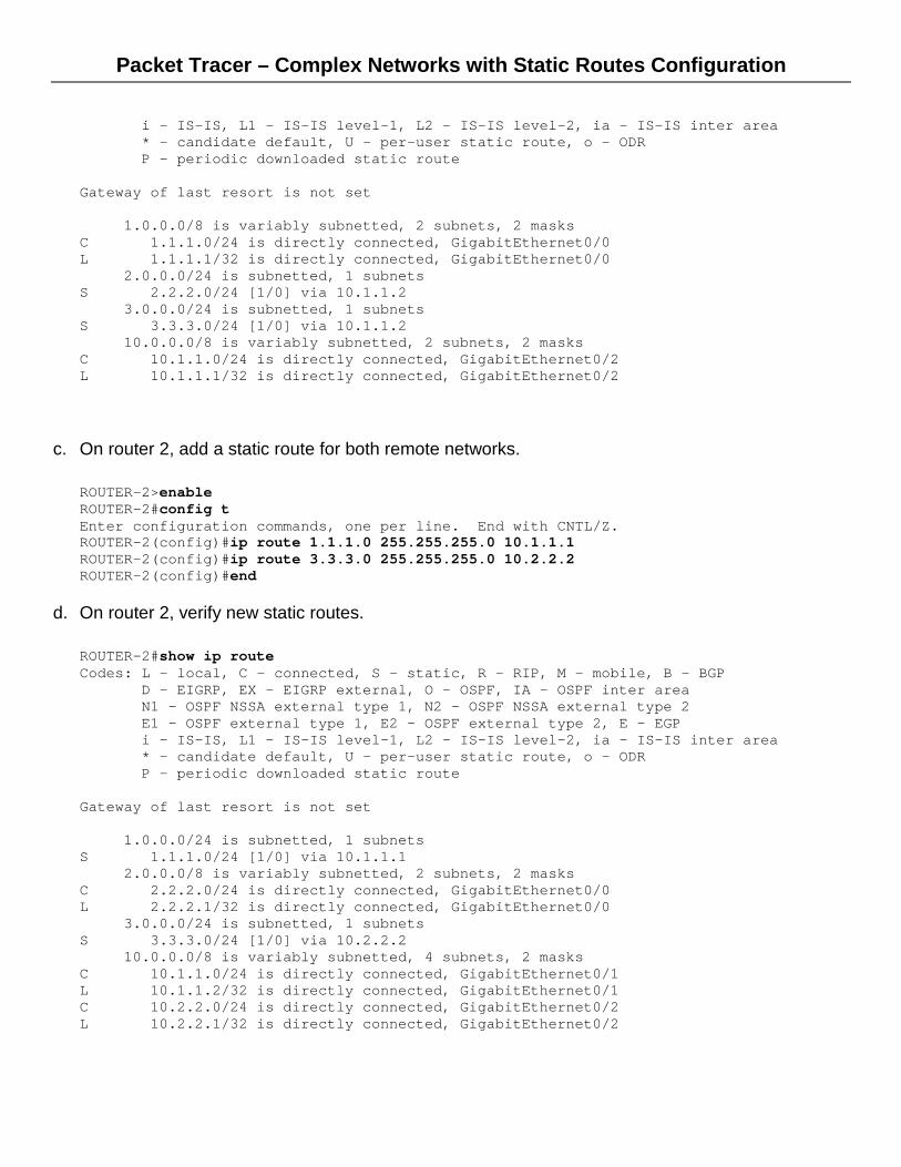
i - IS-IS, L1 - IS-IS level-1, L2 - IS-IS level-2, ia - IS-IS inter area * - candidate default, U - per-user static route, o - ODR P - periodic downloaded static route Gateway of last resort is not set 1.0.0.0/8 is variably subnetted, 2 subnets, 2 masks C 1.1.1.0/24 is directly connected, GigabitEthernet0/0 L 1.1.1.1/32 is directly connected, GigabitEthernet0/0 2.0.0.0/24 is subnetted, 1 subnets S 2.2.2.0/24 [1/0] via 10.1.1.2 3.0.0.0/24 is subnetted, 1 subnets S 3.3.3.0/24 [1/0] via 10.1.1.2 10.0.0.0/8 is variably subnetted, 2 subnets, 2 masks C 10.1.1.0/24 is directly connected, GigabitEthernet0/2 L 10.1.1.1/32 is directly connected, GigabitEthernet0/2
c. On router 2, add a static route for both remote networks.
ROUTER-2>enable ROUTER-2#config t Enter configuration commands, one per line. End with CNTL/Z. ROUTER-2(config)#ip route 1.1.1.0 255.255.255.0 10.1.1.1 ROUTER-2(config)#ip route 3.3.3.0 255.255.255.0 10.2.2.2 ROUTER-2(config)#end
d. On router 2, verify new static routes.
ROUTER-2#show ip route Codes: L - local, C - connected, S - static, R - RIP, M - mobile, B - BGP D - EIGRP, EX - EIGRP external, O - OSPF, IA - OSPF inter area N1 - OSPF NSSA external type 1, N2 - OSPF NSSA external type 2 E1 - OSPF external type 1, E2 - OSPF external type 2, E - EGP i - IS-IS, L1 - IS-IS level-1, L2 - IS-IS level-2, ia - IS-IS inter area * - candidate default, U - per-user static route, o - ODR P - periodic downloaded static route Gateway of last resort is not set 1.0.0.0/24 is subnetted, 1 subnets S 1.1.1.0/24 [1/0] via 10.1.1.1 2.0.0.0/8 is variably subnetted, 2 subnets, 2 masks C 2.2.2.0/24 is directly connected, GigabitEthernet0/0 L 2.2.2.1/32 is directly connected, GigabitEthernet0/0 3.0.0.0/24 is subnetted, 1 subnets S 3.3.3.0/24 [1/0] via 10.2.2.2 10.0.0.0/8 is variably subnetted, 4 subnets, 2 masks C 10.1.1.0/24 is directly connected, GigabitEthernet0/1 L 10.1.1.2/32 is directly connected, GigabitEthernet0/1 C 10.2.2.0/24 is directly connected, GigabitEthernet0/2 L 10.2.2.1/32 is directly connected, GigabitEthernet0/2
Packet Tracer – Complex Networks with Static Routes Configuration
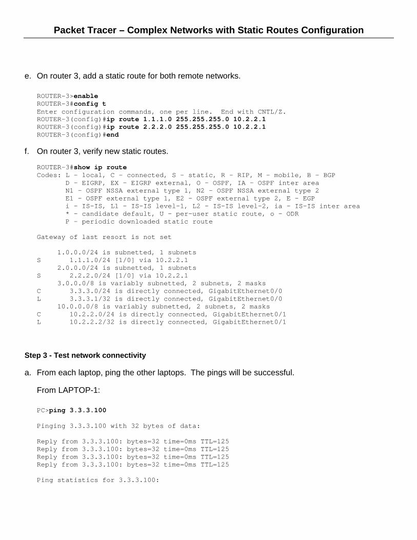
e. On router 3, add a static route for both remote networks.
ROUTER-3>enable ROUTER-3#config t Enter configuration commands, one per line. End with CNTL/Z. ROUTER-3(config)#ip route 1.1.1.0 255.255.255.0 10.2.2.1 ROUTER-3(config)#ip route 2.2.2.0 255.255.255.0 10.2.2.1 ROUTER-3(config)#end
f. On router 3, verify new static routes.
ROUTER-3#show ip route Codes: L - local, C - connected, S - static, R - RIP, M - mobile, B - BGP D - EIGRP, EX - EIGRP external, O - OSPF, IA - OSPF inter area N1 - OSPF NSSA external type 1, N2 - OSPF NSSA external type 2 E1 - OSPF external type 1, E2 - OSPF external type 2, E - EGP i - IS-IS, L1 - IS-IS level-1, L2 - IS-IS level-2, ia - IS-IS inter area * - candidate default, U - per-user static route, o - ODR P - periodic downloaded static route Gateway of last resort is not set 1.0.0.0/24 is subnetted, 1 subnets S 1.1.1.0/24 [1/0] via 10.2.2.1 2.0.0.0/24 is subnetted, 1 subnets S 2.2.2.0/24 [1/0] via 10.2.2.1 3.0.0.0/8 is variably subnetted, 2 subnets, 2 masks C 3.3.3.0/24 is directly connected, GigabitEthernet0/0 L 3.3.3.1/32 is directly connected, GigabitEthernet0/0 10.0.0.0/8 is variably subnetted, 2 subnets, 2 masks C 10.2.2.0/24 is directly connected, GigabitEthernet0/1 L 10.2.2.2/32 is directly connected, GigabitEthernet0/1
Step 3 - Test network connectivity
a. From each laptop, ping the other laptops. The pings will be successful.
From LAPTOP-1: PC>ping 3.3.3.100 Pinging 3.3.3.100 with 32 bytes of data: Reply from 3.3.3.100: bytes=32 time=0ms TTL=125 Reply from 3.3.3.100: bytes=32 time=0ms TTL=125 Reply from 3.3.3.100: bytes=32 time=0ms TTL=125 Reply from 3.3.3.100: bytes=32 time=0ms TTL=125 Ping statistics for 3.3.3.100:
Packet Tracer – Complex Networks with Static Routes Configuration
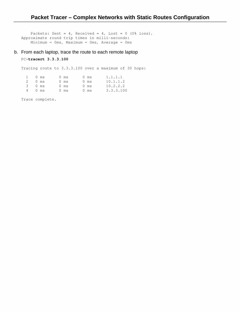
Packets: Sent = 4, Received = 4, Lost = 0 (0% loss), Approximate round trip times in milli-seconds: Minimum = 0ms, Maximum = 0ms, Average = 0ms
b. From each laptop, trace the route to each remote laptop PC>tracert 3.3.3.100 Tracing route to 3.3.3.100 over a maximum of 30 hops: 1 0 ms 0 ms 0 ms 1.1.1.1 2 0 ms 0 ms 0 ms 10.1.1.2 3 0 ms 0 ms 0 ms 10.2.2.2 4 0 ms 0 ms 0 ms 3.3.3.100 Trace complete.

Packet Tracer - Configuring Extended ACLs
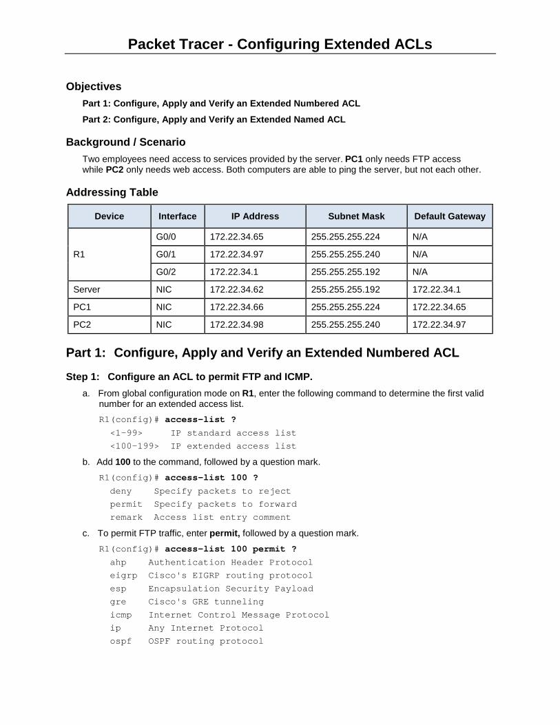
Objectives Part 1: Configure, Apply and Verify an Extended Numbered ACL
Part 2: Configure, Apply and Verify an Extended Named ACL
Background / Scenario Two employees need access to services provided by the server. PC1 only needs FTP access while PC2 only needs web access. Both computers are able to ping the server, but not each other.
Addressing Table
Device Interface IP Address Subnet Mask Default Gateway
R1
G0/0 172.22.34.65 255.255.255.224 N/A
G0/1 172.22.34.97 255.255.255.240 N/A
G0/2 172.22.34.1 255.255.255.192 N/A
Server NIC 172.22.34.62 255.255.255.192 172.22.34.1
PC1 NIC 172.22.34.66 255.255.255.224 172.22.34.65
PC2 NIC 172.22.34.98 255.255.255.240 172.22.34.97
Part 1: Configure, Apply and Verify an Extended Numbered ACL
Step 1: Configure an ACL to permit FTP and ICMP. a. From global configuration mode on R1, enter the following command to determine the first valid
number for an extended access list. R1(config)# access-list ? <1-99> IP standard access list <100-199> IP extended access list
b. Add 100 to the command, followed by a question mark.
R1(config)# access-list 100 ? deny Specify packets to reject permit Specify packets to forward remark Access list entry comment
c. To permit FTP traffic, enter permit, followed by a question mark.
R1(config)# access-list 100 permit ? ahp Authentication Header Protocol eigrp Cisco's EIGRP routing protocol esp Encapsulation Security Payload gre Cisco's GRE tunneling icmp Internet Control Message Protocol ip Any Internet Protocol ospf OSPF routing protocol
Packet Tracer - Configuring Extended ACLs
tcp Transmission Control Protocol udp User Datagram Protocol
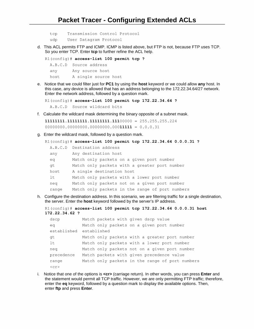
d. This ACL permits FTP and ICMP. ICMP is listed above, but FTP is not, because FTP uses TCP. So you enter TCP. Enter tcp to further refine the ACL help.
R1(config)# access-list 100 permit tcp ? A.B.C.D Source address any Any source host host A single source host
e. Notice that we could filter just for PC1 by using the host keyword or we could allow any host. In this case, any device is allowed that has an address belonging to the 172.22.34.64/27 network. Enter the network address, followed by a question mark. R1(config)# access-list 100 permit tcp 172.22.34.64 ? A.B.C.D Source wildcard bits
f. Calculate the wildcard mask determining the binary opposite of a subnet mask. 11111111.11111111.11111111.11100000 = 255.255.255.224 00000000.00000000.00000000.00011111 = 0.0.0.31
g. Enter the wildcard mask, followed by a question mark. R1(config)# access-list 100 permit tcp 172.22.34.64 0.0.0.31 ? A.B.C.D Destination address any Any destination host eq Match only packets on a given port number gt Match only packets with a greater port number host A single destination host lt Match only packets with a lower port number neq Match only packets not on a given port number range Match only packets in the range of port numbers
h. Configure the destination address. In this scenario, we are filtering traffic for a single destination, the server. Enter the host keyword followed by the server’s IP address.
R1(config)# access-list 100 permit tcp 172.22.34.64 0.0.0.31 host 172.22.34.62 ? dscp Match packets with given dscp value eq Match only packets on a given port number established established gt Match only packets with a greater port number lt Match only packets with a lower port number neq Match only packets not on a given port number precedence Match packets with given precedence value range Match only packets in the range of port numbers <cr>
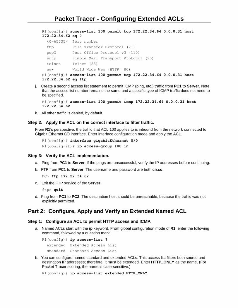
i. Notice that one of the options is <cr> (carriage return). In other words, you can press Enter and the statement would permit all TCP traffic. However, we are only permitting FTP traffic; therefore, enter the eq keyword, followed by a question mark to display the available options. Then, enter ftp and press Enter.
Packet Tracer - Configuring Extended ACLs
R1(config)# access-list 100 permit tcp 172.22.34.64 0.0.0.31 host 172.22.34.62 eq ? <0-65535> Port number ftp File Transfer Protocol (21) pop3 Post Office Protocol v3 (110) smtp Simple Mail Transport Protocol (25) telnet Telnet (23) www World Wide Web (HTTP, 80) R1(config)# access-list 100 permit tcp 172.22.34.64 0.0.0.31 host 172.22.34.62 eq ftp
j. Create a second access list statement to permit ICMP (ping, etc.) traffic from PC1 to Server. Note that the access list number remains the same and a specific type of ICMP traffic does not need to be specified. R1(config)# access-list 100 permit icmp 172.22.34.64 0.0.0.31 host 172.22.34.62
k. All other traffic is denied, by default.
Step 2: Apply the ACL on the correct interface to filter traffic. From R1’s perspective, the traffic that ACL 100 applies to is inbound from the network connected to Gigabit Ethernet 0/0 interface. Enter interface configuration mode and apply the ACL.
R1(config)# interface gigabitEthernet 0/0 R1(config-if)# ip access-group 100 in
Step 3: Verify the ACL implementation. a. Ping from PC1 to Server. If the pings are unsuccessful, verify the IP addresses before continuing.
b. FTP from PC1 to Server. The username and password are both cisco.
PC> ftp 172.22.34.62 c. Exit the FTP service of the Server.
ftp> quit d. Ping from PC1 to PC2. The destination host should be unreachable, because the traffic was not
explicitly permitted.
Part 2: Configure, Apply and Verify an Extended Named ACL
Step 1: Configure an ACL to permit HTTP access and ICMP. a. Named ACLs start with the ip keyword. From global configuration mode of R1, enter the following
command, followed by a question mark. R1(config)# ip access-list ? extended Extended Access List standard Standard Access List
b. You can configure named standard and extended ACLs. This access list filters both source and destination IP addresses; therefore, it must be extended. Enter HTTP_ONLY as the name. (For Packet Tracer scoring, the name is case-sensitive.) R1(config)# ip access-list extended HTTP_ONLY
Packet Tracer - Configuring Extended ACLs
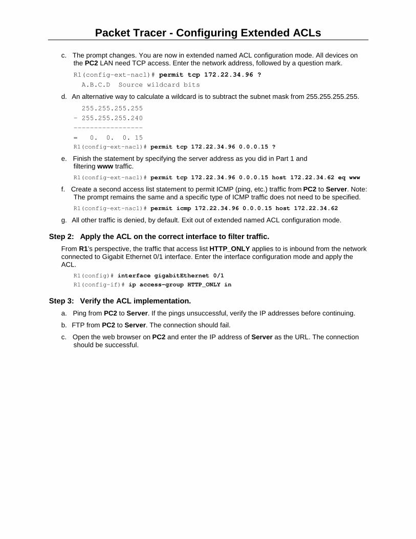
c. The prompt changes. You are now in extended named ACL configuration mode. All devices on the PC2 LAN need TCP access. Enter the network address, followed by a question mark. R1(config-ext-nacl)# permit tcp 172.22.34.96 ? A.B.C.D Source wildcard bits
d. An alternative way to calculate a wildcard is to subtract the subnet mask from 255.255.255.255.
255.255.255.255 - 255.255.255.240 ----------------- = 0. 0. 0. 15 R1(config-ext-nacl)# permit tcp 172.22.34.96 0.0.0.15 ?
e. Finish the statement by specifying the server address as you did in Part 1 and filtering www traffic. R1(config-ext-nacl)# permit tcp 172.22.34.96 0.0.0.15 host 172.22.34.62 eq www
f. Create a second access list statement to permit ICMP (ping, etc.) traffic from PC2 to Server. Note: The prompt remains the same and a specific type of ICMP traffic does not need to be specified. R1(config-ext-nacl)# permit icmp 172.22.34.96 0.0.0.15 host 172.22.34.62
g. All other traffic is denied, by default. Exit out of extended named ACL configuration mode.
Step 2: Apply the ACL on the correct interface to filter traffic. From R1’s perspective, the traffic that access list HTTP_ONLY applies to is inbound from the network connected to Gigabit Ethernet 0/1 interface. Enter the interface configuration mode and apply the ACL.
R1(config)# interface gigabitEthernet 0/1 R1(config-if)# ip access-group HTTP_ONLY in
Step 3: Verify the ACL implementation. a. Ping from PC2 to Server. If the pings unsuccessful, verify the IP addresses before continuing.
b. FTP from PC2 to Server. The connection should fail.
c. Open the web browser on PC2 and enter the IP address of Server as the URL. The connection should be successful.

Packet Tracer – DMZ Configuration
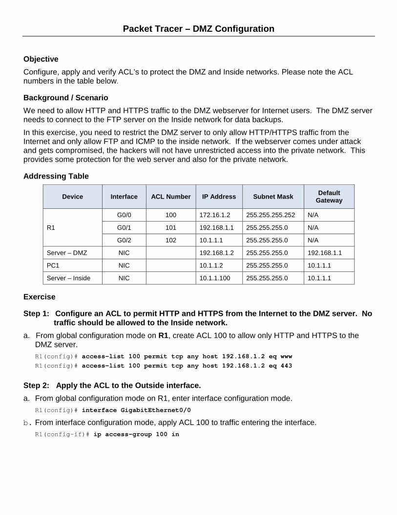
Objective Configure, apply and verify ACL’s to protect the DMZ and Inside networks. Please note the ACL numbers in the table below.
Background / Scenario We need to allow HTTP and HTTPS traffic to the DMZ webserver for Internet users. The DMZ server needs to connect to the FTP server on the Inside network for data backups. In this exercise, you need to restrict the DMZ server to only allow HTTP/HTTPS traffic from the Internet and only allow FTP and ICMP to the inside network. If the webserver comes under attack and gets compromised, the hackers will not have unrestricted access into the private network. This provides some protection for the web server and also for the private network.
Addressing Table
Device Interface ACL Number IP Address Subnet Mask Default Gateway
R1
G0/0 100 172.16.1.2 255.255.255.252 N/A
G0/1 101 192.168.1.1 255.255.255.0 N/A
G0/2 102 10.1.1.1 255.255.255.0 N/A
Server – DMZ NIC 192.168.1.2 255.255.255.0 192.168.1.1
PC1 NIC 10.1.1.2 255.255.255.0 10.1.1.1
Server – Inside NIC 10.1.1.100 255.255.255.0 10.1.1.1
Exercise
Step 1: Configure an ACL to permit HTTP and HTTPS from the Internet to the DMZ server. No traffic should be allowed to the Inside network.
a. From global configuration mode on R1, create ACL 100 to allow only HTTP and HTTPS to the DMZ server. R1(config)# access-list 100 permit tcp any host 192.168.1.2 eq www R1(config)# access-list 100 permit tcp any host 192.168.1.2 eq 443
Step 2: Apply the ACL to the Outside interface. a. From global configuration mode on R1, enter interface configuration mode.
R1(config)# interface GigabitEthernet0/0
b. From interface configuration mode, apply ACL 100 to traffic entering the interface. R1(config-if)# ip access-group 100 in
Packet Tracer – DMZ Configuration
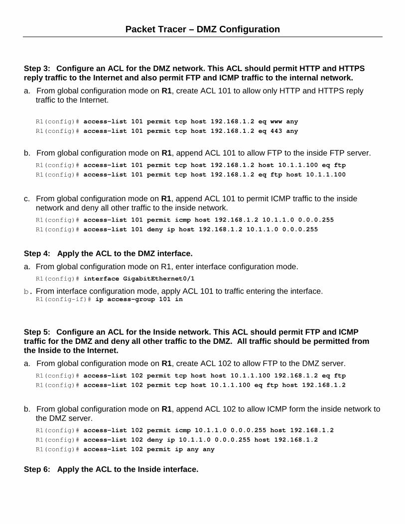
Step 3: Configure an ACL for the DMZ network. This ACL should permit HTTP and HTTPS reply traffic to the Internet and also permit FTP and ICMP traffic to the internal network. a. From global configuration mode on R1, create ACL 101 to allow only HTTP and HTTPS reply
traffic to the Internet. R1(config)# access-list 101 permit tcp host 192.168.1.2 eq www any R1(config)# access-list 101 permit tcp host 192.168.1.2 eq 443 any
b. From global configuration mode on R1, append ACL 101 to allow FTP to the inside FTP server.
R1(config)# access-list 101 permit tcp host 192.168.1.2 host 10.1.1.100 eq ftp R1(config)# access-list 101 permit tcp host 192.168.1.2 eq ftp host 10.1.1.100
c. From global configuration mode on R1, append ACL 101 to permit ICMP traffic to the inside network and deny all other traffic to the inside network. R1(config)# access-list 101 permit icmp host 192.168.1.2 10.1.1.0 0.0.0.255 R1(config)# access-list 101 deny ip host 192.168.1.2 10.1.1.0 0.0.0.255
Step 4: Apply the ACL to the DMZ interface. a. From global configuration mode on R1, enter interface configuration mode.
R1(config)# interface GigabitEthernet0/1
b. From interface configuration mode, apply ACL 101 to traffic entering the interface. R1(config-if)# ip access-group 101 in
Step 5: Configure an ACL for the Inside network. This ACL should permit FTP and ICMP traffic for the DMZ and deny all other traffic to the DMZ. All traffic should be permitted from the Inside to the Internet. a. From global configuration mode on R1, create ACL 102 to allow FTP to the DMZ server.
R1(config)# access-list 102 permit tcp host host 10.1.1.100 192.168.1.2 eq ftp R1(config)# access-list 102 permit tcp host 10.1.1.100 eq ftp host 192.168.1.2
b. From global configuration mode on R1, append ACL 102 to allow ICMP form the inside network to
the DMZ server. R1(config)# access-list 102 permit icmp 10.1.1.0 0.0.0.255 host 192.168.1.2 R1(config)# access-list 102 deny ip 10.1.1.0 0.0.0.255 host 192.168.1.2 R1(config)# access-list 102 permit ip any any
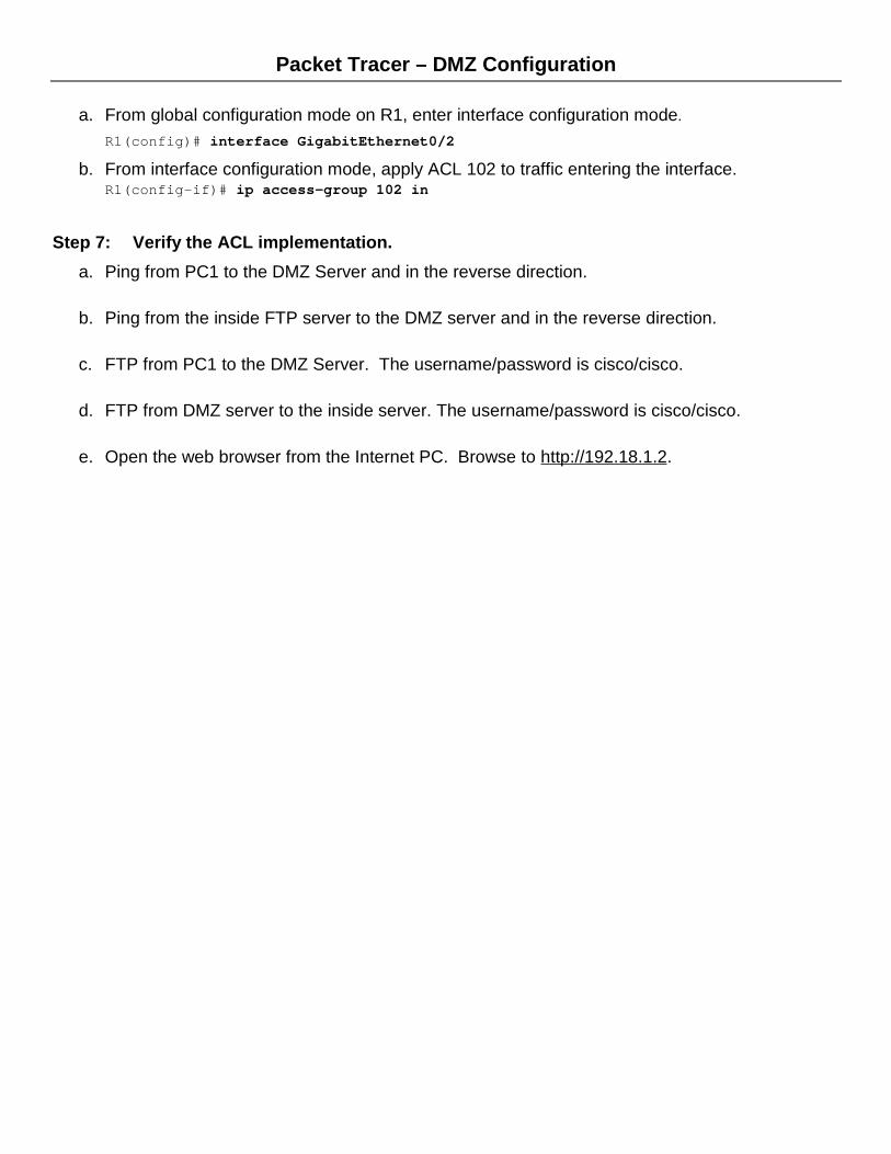
Step 6: Apply the ACL to the Inside interface.
Packet Tracer – DMZ Configuration
a. From global configuration mode on R1, enter interface configuration mode.
R1(config)# interface GigabitEthernet0/2
b. From interface configuration mode, apply ACL 102 to traffic entering the interface. R1(config-if)# ip access-group 102 in
Step 7: Verify the ACL implementation. a. Ping from PC1 to the DMZ Server and in the reverse direction.
b. Ping from the inside FTP server to the DMZ server and in the reverse direction.
c. FTP from PC1 to the DMZ Server. The username/password is cisco/cisco.
d. FTP from DMZ server to the inside server. The username/password is cisco/cisco.
e. Open the web browser from the Internet PC. Browse to http://192.18.1.2.