complex numerical analysis of the tube forming process ... · 719 table 1 list of parameters for...
TRANSCRIPT

A R C H I V E S O F M E T A L L U R G Y A N D M A T E R I A L S
Volume 58 2013 Issue 3
DOI: 10.2478/amm-2013-0060
Z. PATER∗, J. KAZANECKI∗∗
COMPLEX NUMERICAL ANALYSIS OF THE TUBE FORMING PROCESS USING DIESCHER MILL
KOMPLEKSOWA ANALIZA NUMERYCZNA PROCESU WALCOWANIA TULEI W WALCARCE DIESCHERA
This paper presents the results of FEM simulations of the rotary piercing process in which disc guiding devices of theDiescher type are used. During this process the material is formed by means of two skew rolls, two guiding devices, and thepiercing plug mounted on the mandrel. The aim of the analysis was to determine the effect of the plug diameter, the plugadvance, the feed angle and the diameter reduction on the piercing process. Nine cases of piercing with three different plugsused were analyzed. The effects of the basic process parameters on the tube shell diameter and the tool load were analyzed.The numerical results obtained using Simufact.Forming 10.0 were verified under experimental conditions in which the tubeshell made from 100Cr6 bearing steel was pierced. The results of the FEM calculations show agreement with the experimentalresults.
Keywords: tube piercing, Diescher mill, FEM analysis, experiment
W artykule zaprezentowano wyniki symulacji numerycznych procesu dziurowania tulei w walcarce skośnej z prowadni-cami tarczowymi Dieschera. W procesie tym materiał jest kształtowany w wyniku oddziaływania dwóch ustawionych skośniewalców, dwóch prowadnic oraz główki dziurującej montowanej na trzpieniu. Celem analizy było określenie wpływu średnicygłówki, wysunięcia główki, kąta zukosowania walców oraz gniotu na przebieg procesu dziurowania. Przeanalizowano dziewięćprzypadków kształtowania, w których wykorzystano trzy rożne główki dziurujące. Określono wpływ podstawowych parametrówprocesu na średnicę tulei kształtowanej oraz obciążenie poszczególnych narzędzi. Wyniki symulacji numerycznej otrzymanej wprogramie Simufact.Forming 10 zweryfikowano w warunkach doświadczalnych, w których dziurowano tuleje ze stali łożyskowejw gatunku 100Cr6. Rezultaty obliczeń MES pozostawały w dobrej zgodności z wynikami uzyskanymi z doświadczeń.
1. Introduction
Skew piercing mills are used to produce thick-walled tubeshells which are then used to produce seamless pipes. Depend-ing on the number of rolls, the skew mills can be divided into:• two-roll mills with two working rolls and two guiding
devices which hold the tube shell along the rolling axis.Such guiding devices may either be roll guides of theMannesmann type, flat guides of the Stiefel type, or discguides of the Diescher type;
• three-roll mills with three working rolls which operatewithout any additional guiding devices for the metal.
Out of the machines enumerated above, the two-roll millsequipped with the conical rolls and with the disc guiding de-vices of the Diescher type have the highest production capacityand guarantee the highest product accuracy [1].
Despite its over a hundred-year-old history of industrialapplications, the rotary piercing process has not been satisfac-torily researched yet, which can be attributed to very complexmaterial flow kinematics. Nevertheless, an intensive develop-ment of numerical modelling methods for volumetric metal
forming processes offers possibilities of improving the currentstate of knowledge about the process.
The first studies on numerical modelling of rotary pierc-ing conducted in the last decade of the twentieth centurywere based on two-dimensional FEM models. For instance,Urbanski et al. [2] assumed an axially-symmetric shape ofthe semi-finished product, omitting, at the same time, thecircumferential material flow, and thereby they were able todetermine strain and temperature distributions in the longitu-dinal section of the semi-finished product. Due to the com-plex material flow, piercing processes should be modelledin three-dimensional state of strain conditions. Pietsch andThievien [3], Ceretti et al. [4], and Komori [5] were the firstto perform the three-dimensional modelling of the piercingprocess. However, the numerical models developed by thementioned authors were based on significant simplifications– for instance, thermal phenomena occurring in the materialwere omitted, the calculations were limited only to the initialor steady state of the piercing process, or they assumed that thematerial being formed is ideally plastic. More developed mod-els of the piercing process which took the thermal phenomena
∗ LUBLIN UNIVERSITY OF TECHNOLOGY, LUBLIN, POLAND∗∗ AGH UNIVERSITY OF SCIENCE AND TECHNOLOGY, AL. A. MICKIEWICZA 30, 30-059 KRAKÓW, POLAND
718
into consideration were presented by Pater et al. [6] and Luet al. [7]. The calculation results obtained by means of suchmodels agree with the experimental test results. However, oneshortcoming of these works is that the analysis was limitedonly to a single piercing case.
Pater and Kazanecki [8] presented the results of a pierc-ing process simulation in which they applied the finite ele-ment method and focused on the analysis of state of stressand temperature distributions in the piercing plug. As a re-sult of the calculations made, they determined that the highestthrusts (approx. 100-180 MPa) occur on the plug nose wherethe temperature quickly rises to exceed 900◦C. It should alsobe mentioned that there were several other studies undertak-en to investigate the piercing process. For example, Komoriand Mizumo [9] used physical modelling (and deformed clayspecimens) to determine the effect of the basic parameters onthe course of piercing by means of the conical rolls. Ghiottiet al. [10] used the Forge software to model the barrel-typerotary piercing process (without the use of the piercing plug)and thus to determine the moment in which material crack-ing occurs in the product being formed. Pschera et al. [11]examined the effect of the feed angle of the rolls on materialcracking in the pierced tube shell. Romanenko et al. [12] usedinfrared mapping to investigate temperature changes in thesemi-finished product during the piercing process.
Summing up the literature overview, it can be observedthat despite a number of works on modelling the rotary tubepiercing process, there is still a need for a complex study whichwould analyze the effect of the basic process parameters onthe course of the process. The present authors have undertakento provide such study, and the present paper will discuss thenumerical simulation results of several cases of the piercingprocess performed using the Diescher mill.
2. Applied model of piercing process and calculationscope
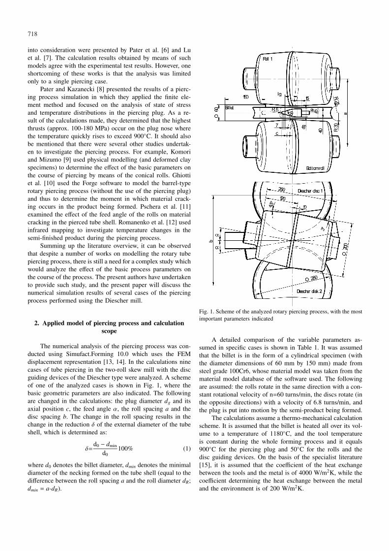
The numerical analysis of the piercing process was con-ducted using Simufact.Forming 10.0 which uses the FEMdisplacement representation [13, 14]. In the calculations ninecases of tube piercing in the two-roll skew mill with the discguiding devices of the Diescher type were analyzed. A schemeof one of the analyzed cases is shown in Fig. 1, where thebasic geometric parameters are also indicated. The followingare changed in the calculations: the plug diameter dg and itsaxial position c, the feed angle α, the roll spacing a and thedisc spacing b. The change in the roll spacing results in thechange in the reduction δ of the external diameter of the tubeshell, which is determined as:
δ=d0 − dmin
d0100% (1)
where d0 denotes the billet diameter, dmin denotes the minimaldiameter of the necking formed on the tube shell (equal to thedifference between the roll spacing a and the roll diameter dR;dmin = a-dR).
Fig. 1. Scheme of the analyzed rotary piercing process, with the mostimportant parameters indicated
A detailed comparison of the variable parameters as-sumed in specific cases is shown in Table 1. It was assumedthat the billet is in the form of a cylindrical specimen (withthe diameter dimensions of 60 mm by 150 mm) made fromsteel grade 100Cr6, whose material model was taken from thematerial model database of the software used. The followingare assumed: the rolls rotate in the same direction with a con-stant rotational velocity of n=60 turns/min, the discs rotate (inthe opposite directions) with a velocity of 6.8 turns/min, andthe plug is put into motion by the semi-product being formed.
The calculations assume a thermo-mechanical calculationscheme. It is assumed that the billet is heated all over its vol-ume to a temperature of 1180◦C, and the tool temperatureis constant during the whole forming process and it equals900◦C for the piercing plug and 50◦C for the rolls and thedisc guiding devices. On the basis of the specialist literature[15], it is assumed that the coefficient of the heat exchangebetween the tools and the metal is of 4000 W/m2K, while thecoefficient determining the heat exchange between the metaland the environment is of 200 W/m2K.
719
TABLE 1List of parameters for rotary piercing cases assumed in numerical simulation
No. Feed angle α Spacing a Spacing b Reduction δ Plug advance c Plug diameter dg Plug length lg Plug radius Rg
1.2.3.4.5.6.7.8.9.
8◦8◦8◦8◦8◦6◦10◦8◦
8◦
252.98 mm252.98 mm252.98 mm252.98 mm252.98 mm252.98 mm252.98 mm251.60 mm250.40 mm
335.64 mm335.64 mm335.64 mm335.64 mm335.64 mm335.64 mm335.64 mm334.18 mm332.92 mm
11.7%11.7%11.7%11.7%11.7%11.7%11.7%14.0%16.0%
35 mm35 mm35 mm32 mm38 mm35 mm35 mm35 mm35 mm
32 mm34 mm36 mm32 mm32 mm32 mm32 mm32 mm32 mm
48.9 mm52.0 mm55.0 mm48.9 mm48.9 mm48.9 mm48.9 mm48.9 mm48.9 mm
114.2 mm118.7 mm123.0 mm114.2 mm114.2 mm114.2 mm114.2 mm114.2 mm114.2 mm
Owing to the changes in the direction of the friction forcesaffecting the material-tool contact surface, the calculations as-sume a constant friction model depending on the metal slip-ping velocity relative to the tool, which is described with theequation:
τ = −mk arctan(vp
ap
)vp∣∣∣vp
∣∣∣ (2)
where m denotes the friction factor, k denotes the pure shearflow stress, vp denotes the slipping velocity vector, ap denotesthe coefficient several times smaller than the slipping velocity(the calculations assume that ap equals 0.1% of the roll veloc-ity). Given the lack of lubrication and purposeful roughnessof the rolls (to make the billet enter in between the rolls moreeasily), it is assumed that the friction factor m for the rollsreaches the boundary value of 1.0. The assumed value of thefriction factor m for the remaining tools (the discs and thepiercing plug) is smaller and it equals 0.7.
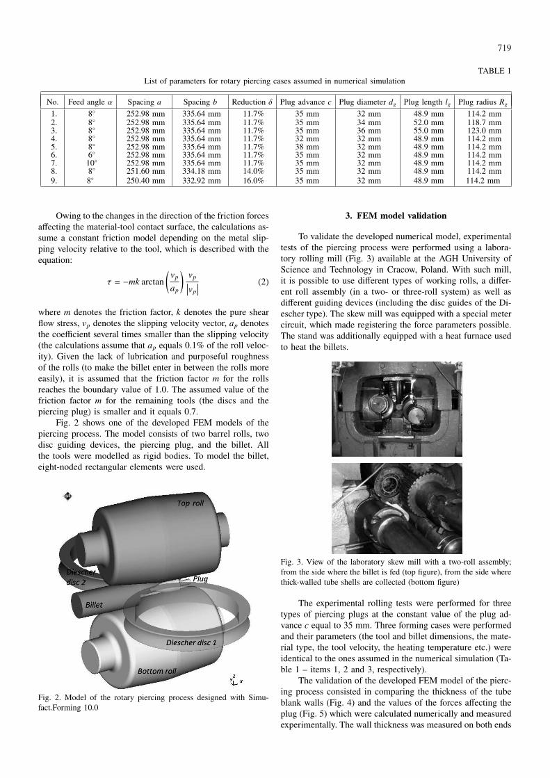
Fig. 2 shows one of the developed FEM models of thepiercing process. The model consists of two barrel rolls, twodisc guiding devices, the piercing plug, and the billet. Allthe tools were modelled as rigid bodies. To model the billet,eight-noded rectangular elements were used.
Fig. 2. Model of the rotary piercing process designed with Simu-fact.Forming 10.0
3. FEM model validation
To validate the developed numerical model, experimentaltests of the piercing process were performed using a labora-tory rolling mill (Fig. 3) available at the AGH University ofScience and Technology in Cracow, Poland. With such mill,it is possible to use different types of working rolls, a differ-ent roll assembly (in a two- or three-roll system) as well asdifferent guiding devices (including the disc guides of the Di-escher type). The skew mill was equipped with a special metercircuit, which made registering the force parameters possible.The stand was additionally equipped with a heat furnace usedto heat the billets.
Fig. 3. View of the laboratory skew mill with a two-roll assembly;from the side where the billet is fed (top figure), from the side wherethick-walled tube shells are collected (bottom figure)
The experimental rolling tests were performed for threetypes of piercing plugs at the constant value of the plug ad-vance c equal to 35 mm. Three forming cases were performedand their parameters (the tool and billet dimensions, the mate-rial type, the tool velocity, the heating temperature etc.) wereidentical to the ones assumed in the numerical simulation (Ta-ble 1 – items 1, 2 and 3, respectively).
The validation of the developed FEM model of the pierc-ing process consisted in comparing the thickness of the tubeblank walls (Fig. 4) and the values of the forces affecting theplug (Fig. 5) which were calculated numerically and measuredexperimentally. The wall thickness was measured on both ends

720
of the tube blank. The comparison of the force values con-cerned the steady state of the piercing process. The analysisof the data shown in Figs. 4 and 5 shows agreement betweenthe numerically calculated parameters and the experimentalresults, which confirms the validity of the developed FEMmodel of the piercing process in the skew mill.
Fig. 4. Comparison of the wall thickness of the tube shells producedin the piercing process at: α =8◦, δ =11.7%, c =35 mm
Fig. 5. Comparison of the forces affecting the plug in the steady stateof the piercing process at: α =8◦, δ =11.7%, c=35 mm
4. Numerical analysis results
The application of the FEM to the analysis of the ro-tary piercing process allows for investigating the semi-finishedproduct shape changes in the course of rolling. The changesare shown in Fig. 6 in which one of the disc guiding devicesis not shown for the purposes of clarity. At the beginning ofthe process, the billet is gripped by the rolls which make itrotate and move it in the axial direction. It is in this formingstage that the rotary compression process is realized, whichcontinues until the plug nose contacts the frontal surface ofthe semi-finished product. What begins then is the formingof a tube shell hole whose dimension predominantly dependson the piercing plug used. In the course of forming the tubeshell hole, the disc guides also contact the metal; as they ro-tate, the disc guides increase the axial forces which put thesemi-finished product on the piercing plug. Once the plug has
completely sunk into the metal, the forming process reachesits steady state which is characterized by a relative stability ofthe forming forces.
Fig. 6. Semi-finished product shape progression in the rotary piercingprocess (case no. 1) with the effective strain distribution indicated
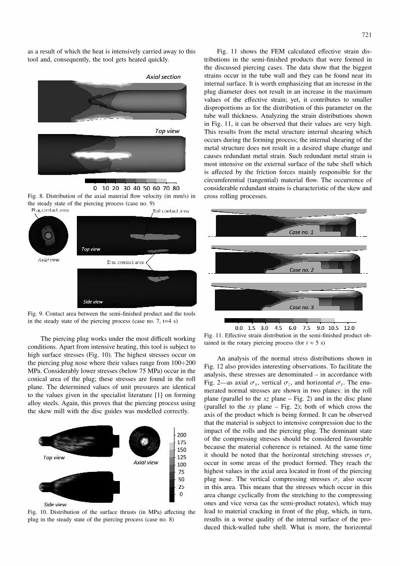
In the course of rolling, the object being formed rotatesand this rotational motion is the dominant one (Fig. 7). Thematerial reaches the highest linear velocity values on the con-tact surface with the rolls. It is also there where the frictionforces occur which make the object rotate and move it in theaxial direction. As a result, the material in the piercing processmoves helically. The most intensive axial material flow occursat the surface area which is adjacent to the rolls, while theleast intensive axial material flow occurs in front of the pierc-ing plug nose. The axial material flow is homogenous all overthe volume of the formed tube shell (Fig. 8).
Fig. 7. Distribution of the material flow velocity (in mm/s) in thesteady state of the piercing process (case no. 9)
Fig. 9 shows the contact areas with the tools in the steadystate of the piercing process. Owing to the impact of the rolls,the material undergoes ovalisation, as a result of which it doesnot contact the plug all over its perimeter. The cross-sectionalovalisation of the semi-finished tube shell is effectively re-moved by the disc guides which prevent the material fromflowing sideways. Fig. 9 also shows that the contact area be-tween the material and the piercing plug is considerably vast,
721
as a result of which the heat is intensively carried away to thistool and, consequently, the tool gets heated quickly.
Fig. 8. Distribution of the axial material flow velocity (in mm/s) inthe steady state of the piercing process (case no. 9)
Fig. 9. Contact area between the semi-finished product and the toolsin the steady state of the piercing process (case no. 7, t=4 s)
The piercing plug works under the most difficult workingconditions. Apart from intensive heating, this tool is subject tohigh surface stresses (Fig. 10). The highest stresses occur onthe piercing plug nose where their values range from 100÷200MPa. Considerably lower stresses (below 75 MPa) occur in theconical area of the plug; these stresses are found in the rollplane. The determined values of unit pressures are identicalto the values given in the specialist literature [1] on formingalloy steels. Again, this proves that the piercing process usingthe skew mill with the disc guides was modelled correctly.
Fig. 10. Distribution of the surface thrusts (in MPa) affecting theplug in the steady state of the piercing process (case no. 8)
Fig. 11 shows the FEM calculated effective strain dis-tributions in the semi-finished products that were formed inthe discussed piercing cases. The data show that the biggeststrains occur in the tube wall and they can be found near itsinternal surface. It is worth emphasizing that an increase in theplug diameter does not result in an increase in the maximumvalues of the effective strain; yet, it contributes to smallerdisproportions as for the distribution of this parameter on thetube wall thickness. Analyzing the strain distributions shownin Fig. 11, it can be observed that their values are very high.This results from the metal structure internal shearing whichoccurs during the forming process; the internal shearing of themetal structure does not result in a desired shape change andcauses redundant metal strain. Such redundant metal strain ismost intensive on the external surface of the tube shell whichis affected by the friction forces mainly responsible for thecircumferential (tangential) material flow. The occurrence ofconsiderable redundant strains is characteristic of the skew andcross rolling processes.
Fig. 11. Effective strain distribution in the semi-finished product ob-tained in the rotary piercing process (for t ≈ 5 s)
An analysis of the normal stress distributions shown inFig. 12 also provides interesting observations. To facilitate theanalysis, these stresses are denominated – in accordance withFig. 2—as axial σx, vertical σz, and horizontal σy. The enu-merated normal stresses are shown in two planes: in the rollplane (parallel to the xz plane – Fig. 2) and in the disc plane(parallel to the xy plane – Fig. 2); both of which cross theaxis of the product which is being formed. It can be observedthat the material is subject to intensive compression due to theimpact of the rolls and the piercing plug. The dominant stateof the compressing stresses should be considered favourablebecause the material coherence is retained. At the same timeit should be noted that the horizontal stretching stresses σy
occur in some areas of the product formed. They reach thehighest values in the axial area located in front of the piercingplug nose. The vertical compressing stresses σz also occurin this area. This means that the stresses which occur in thisarea change cyclically from the stretching to the compressingones and vice versa (as the semi-product rotates), which maylead to material cracking in front of the plug, which, in turn,results in a worse quality of the internal surface of the pro-duced thick-walled tube shell. What is more, the horizontal

722
stretching stresses σy occur on the internal surface of the tube(in the roll plane), which results from an increase in the tubehole diameter occurring during the sizing stage of the piercingprocess (when the tube comes off the plug).
Fig. 12. Normal stress distribution (in MPa) in the semi-finishedproduct determined in the steady state stage of the piercing process(case no. 9)
Fig. 13. Temperature distribution (in ◦C) in the pierced semi-finishedproduct (case no. 8, t=5.2 s)
Fig. 13 shows temperature distributions of the productformed in the piercing process. Despite a relatively long form-ing time, the metal temperature of the wall of the rolled tubeis equal to the billet temperature (1180◦C). It is so becausethe heat generated by the strain work and by the friction workcompensates for the losses of the heat carried away to thetools. The lowest temperature values are observed at the ends
of the product formed, as it there where the optimal conditionsfor carrying away of the heat to the environment occur.
The application of the FEM allows for a precise deter-mining of particular tool loads during the piercing stage. Dis-tributions of the forces with which the tools affect the materialin one of the analyzed forming cases are shown in Fig. 14;additionally, the figure schematically shows the shape progres-sion of the semi-finished product. It can be noted that all theforces gradually increase their values at the beginning untilthe moment when the tube shell comes off the piercing plug.After that, the steady state of the process begins in which theforce values are maintained on the constant level. It is worthnoting that the load of both rolls is practically identical. Somedifferences can be noticed in the load distributions of particu-lar disc guides, which is a result of uneven clamping pressureof the semi-finished product to the tools. The forces affectingthe rolls are two times bigger than the forces which occur onthe discs and the piercing plug.
Fig. 14. Distributions of the forces affecting the tools (indicatedaccording to Fig. 2) in the piercing process (case no. 8)
The distribution of the turning moments of the rolls andof the disc guides, which is illustrated in Fig. 15, can be used todetermine power demand of the mill. It can be clearly observedthat the roll driver plays a decisive role in this respect. Theturning moment of the discs is several times smaller, whichpredominantly results from the position of the resultant forceaffecting the disc; the force is pointed at a small angle towardthe z direction that overlaps with the direction of the disc ro-tation axis. As for the distribution of the turning moments, itcan be stated that it is similar to the force distributions shownin Fig. 14.
Fig. 15. Distributions of the turning moments affecting the tools(indicated according to Fig. 2) in the piercing process (case No. 8)
723
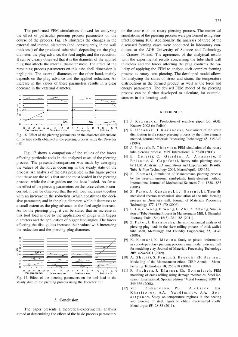
The performed FEM simulations allowed for analyzingthe effect of particular piercing process parameters on thecourse of the process. Fig. 16 illustrates the changes in theexternal and internal diameters (and, consequently, in the wallthickness) of the produced tube shell depending on the plugdiameter, the plug advance, the feed angle, and the reduction.It can be clearly observed that it is the diameter of the appliedplug that affects the internal diameter most. The effect of theremaining process parameters on this tube shell dimension isnegligible. The external diameter, on the other hand, mainlydepends on the plug advance and the applied reduction. Anincrease in the values of these parameters results in a cleardecrease in the external diameter.
Fig. 16. Effect of the piercing parameters on the diameter dimensionsof the tube shells obtained in the piercing process using the Dieschermill
Fig. 17 shows a comparison of the values of the forcesaffecting particular tools in the analyzed cases of the piercingprocess. The presented comparison was made by averagingthe values of the forces occurring in the steady state of theprocess. An analysis of the data presented in this figure provesthat these are the rolls that are the most loaded in the piercingprocess, while the disc guides are the least loaded. As far asthe effect of the piercing parameters on the force values is con-cerned, it can be observed that the roll load increases togetherwith an increase in the reduction (which constitutes the deci-sive parameter) and in the plug diameter, while it decreases toa small extent as the plug advance or the feed angle increase.As for the piercing plug, it can be stated that an increase inthis tool load is due to the application of plugs with biggerdiameters and the application of bigger feed angles. The forcesaffecting the disc guides increase their values with increasingthe reduction and the piercing plug diameter.
Fig. 17. Effect of the piercing parameters on the tool load in thesteady state of the piercing process using the Diescher mill
5. Conclusion
The paper presents a theoretical-experimental analysisaimed at determining the effect of the basic process parameters
on the course of the rotary piercing process. The numericalsimulations of the piercing process were performed using Sim-ufact.Forming 10.0. Additionally, the analyses of three of thediscussed forming cases were conducted in laboratory con-ditions at the AGH University of Science and Technologyin Cracow, Poland. The agreement of the analytical resultswith the experimental results concerning the tube shell wallthickness and the forces affecting the plug confirms the va-lidity of applying the FEM to analyse such complex formingprocess as rotary tube piercing. The developed model allowsfor analyzing the states of stress and strain, the temperaturedistributions in the formed product as well as the force andenergy parameters. The devised FEM model of the piercingprocess can be further developed to calculate, for example,stresses in the forming tools.
REFERENCES
[1] J. K a z a n e c k i, Production of seamless pipes. Ed. AGH,Krakow 2003 (in Polish).
[2] S. U r b a ń s k i, J. K a z a n e c k i, Assessment of the straindistribution in the rotary piercing process by the finite elementmethod, Journal Materials Processing Technology 45, 335-340(1994).
[3] J. P i e t s c h, P. T h i e v i e n, FEM simulation of the rotarytube piercing process, MPT International 2, 52-60 (2003).
[4] E. C e r e t t i, C. G i a r d i n i, A. A t t a n a s i o, F.B r i s o t t o, G. C a p o f e r r i, Rotary tube piercing studyby FEM Analysis: 3D simulations and Experimental Results,Tube & Pipe Technology 2004, March/April, 155-159.
[5] K. K o m o r i, Simulation of Mannesmann piercing processby the three-dimensional rigid-plastic finite-element method,International Journal of Mechanical Sciences 7, 4, 1838-1853(2005).
[6] Z. P a t e r, J. K a z a n e c k i, J. B a r t n i c k i, Three di-mensional thermo-mechanical simulation of the tube formingprocess in Diescher’s mill, Journal of Materials ProcessingTechnology 177, 167-170 (2006).
[7] L. L u, Z. W a n g, F. W a n g, G. Z h u, X. Z h a n g, Simula-tion of Tube Forming Process in Mannesmann Mill, J. ShanghaiJiaotong Univ. (Sci) 16(3), 281-185 (2011).
[8] Z. P a t e r, J. K a z a n e c k i, Thermo-mechanical analysis ofpiercing plug loads in the skew rolling process of thick-walledtube shell, Metallurgy and Foundry Engineering 32, 31-40(2006).
[9] K. K o m o r i, K. M i z u n o, Study on plastic deformationin cone-type rotary piercing process using model piercing millfor modeling clay, Journal of Materials Processing Technology209, 4994-5001 (2009).
[10] A. G h i o t t i, S. F a n i n i, S. B r u s c h i, P.F. B a r i a n u,Modelling of the Mannesmann effect, CIRP Annals – Manu-facturing Technology 58, 255-258 (2009).
[11] R. P s c h e r a, J. K l a r n e r, Ch. S o m m i t s c h, FEMmodeling of cross rolling using damage mechanics. Steel Re-search International. Special edition ”Metal Forming 2008” 1,349-356 (2008).
[12] V.P. R o m a n e n k o, P.L. A l e k s e e v, E.A.K h a r i t o n o v, A.A. Ya n d i m i r o v, A.A. S e v -a s t y a n o v, Study on temperature regimes in the heatingand piercing of steel ingots to obtain thick-walled shells.Metallurgist 55, 28-33 (2011).

724
[13] Z. P a t e r, A. T o f i l, Experimental and theoretical analysisof the cross – wedge rolling process in cold forming conditions.Archives of Metallurgy and Materials 52 (2), 289-297 (2007).
[14] Z. P a t e r, A. G o n t a r z, G. S a m o ł y k, J. B a r t n i c -k i, Analysis of cross rolling process of toothed titanium shafts.Archives of Metallurgy and Materials 54 (3), 617-626 (2009).
[15] J.C. P r i n c e, R. M a r o n o, F. L e o n, Thermomechanicalanalysis of a piercing mandrel for the production of seamlesssteel tubes. Proceedings of the Institution of Mechanical Engi-neers, Part E: Journal of Process Mechanical Engineering 217,337-34 (2003).
Received: 20 March 2012.