complex signal processing is not — complex
TRANSCRIPT
Complex Signal Processing is Not — ComplexKen Martin
[email protected]. of Elect. and Comp. Engr., Univ. of Toronto,
Toronto, ON Canada M5S 3G4
Abstract: Wireless systems often make use of the quadrature relationship between pairs of signals to effectively cancel out-of-band and interfering in-band signal components. The understanding of these systems is often simplified by consider-ing both the signals and system transfer-functions as ‘complex’quantities. The complex approach is especially useful in highly-integrated multi-standard receivers where the use of narrow-band fixed-coefficient filters at the RF and high IF fre-quencies must be minimized. A tutorial review of complex sig-nal processing for wireless applications emphasizing a graphical and pictorial description rather than an equa-tion-based approach is first presented. Next, a number of clas-sical modulation architectures are described using this formulation. Finally, more recent developments such as com-plex filters, image-reject mixers, low-IF receivers, and over-sampling A/D converters are discussed.
1. Introduction A complex signal consists of a pair of real signals at an
instance in time. If one denotes the complex signal, , as , where , then a Hilbert Space
can be defined using appropriate definitions for addition, mul-tiplication, and an inner-product and norm. In an actual physi-cal system, the signals are both real (but are called the real and imaginary parts) and are found in two distinct signal paths. The multiplier ‘ ’ is used to help define operations between differ-ent complex signals, and is to some degree imaginary, i.e., it doesn’t actually exist in real systems. Often the dependence of signals on time is not shown explicitly.
The use of complex signal processing to describe wireless systems is increasingly important and ubiquitous for the fol-lowing reasons: it often allows for image-reject architectures to be described more compactly and simply, it leads to a graphical or signal-flow-graph (SFG) description of signal-processing systems that gives insight, and it often leads to the develop-ment of new systems where the use of high-frequency, highly selective image-reject filters is minimized leading to more highly integrated transceivers using less power and requiring less physical space.
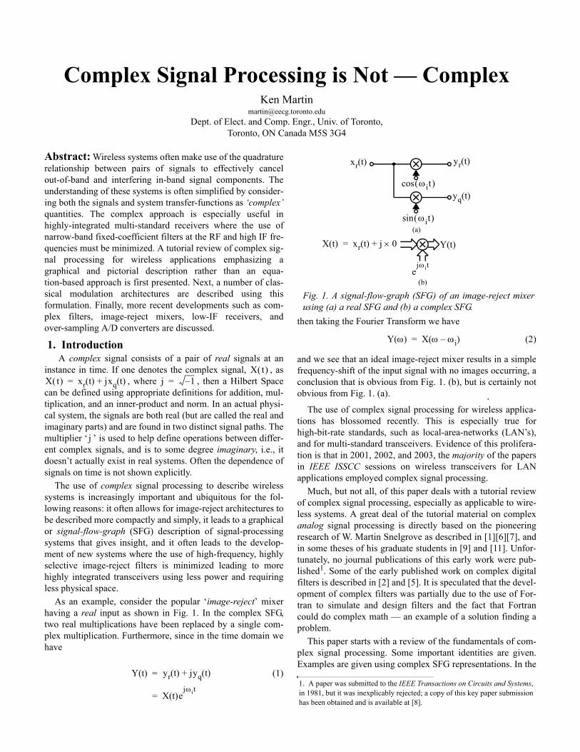
As an example, consider the popular ‘image-reject’ mixer having a real input as shown in Fig. 1. In the complex SFG, two real multiplications have been replaced by a single com-plex multiplication. Furthermore, since in the time domain we have
(1)
then taking the Fourier Transform we have
(2)
and we see that an ideal image-reject mixer results in a simple frequency-shift of the input signal with no images occurring, a conclusion that is obvious from Fig. 1. (b), but is certainly not obvious from Fig. 1. (a).
The use of complex signal processing for wireless applica-tions has blossomed recently. This is especially true for high-bit-rate standards, such as local-area-networks (LAN’s), and for multi-standard transceivers. Evidence of this prolifera-tion is that in 2001, 2002, and 2003, the majority of the papers in IEEE ISSCC sessions on wireless transceivers for LAN applications employed complex signal processing.
Much, but not all, of this paper deals with a tutorial review of complex signal processing, especially as applicable to wire-less systems. A great deal of the tutorial material on complex analog signal processing is directly based on the pioneering research of W. Martin Snelgrove as described in [1][6][7], and in some theses of his graduate students in [9] and [11]. Unfor-tunately, no journal publications of this early work were pub-lished1. Some of the early published work on complex digital filters is described in [2] and [5]. It is speculated that the devel-opment of complex filters was partially due to the use of For-tran to simulate and design filters and the fact that Fortran could do complex math — an example of a solution finding a problem.
This paper starts with a review of the fundamentals of com-plex signal processing. Some important identities are given. Examples are given using complex SFG representations. In the
X t( )X t( ) xr t( ) jxq t( )+= j 1–=
j
Y t( ) yr t( ) jyq t( )+
X t( )ejωi t=
=
Fig. 1. A signal-flow-graph (SFG) of an image-reject mixer using (a) a real SFG and (b) a complex SFG.
1. A paper was submitted to the IEEE Transactions on Circuits and Systems, in 1981, but it was inexplicably rejected; a copy of this key paper submission has been obtained and is available at [8].
ωit( )cos
ωit( )sin
X t( ) xr t( ) j 0×+=
yq t( )
yr t( )
ejωi t
Y t( )
(a)
(b)
xr t( )
Y ω( ) X ω ωi–( )=
third section, a number of classical wireless modulations sys-tems are described using the complex formulation. These sys-tems include Weaver and Hartley modulators and polyphase filters. Errors due to non-ideal coefficients in mixers are quan-tified. In the fourth section, complex analog and digital filters are discussed. The fifth section describes more-recent complex signal-processing applications. These include complex adap-tive image-reject mixers, complex low-IF receiver architec-tures including a new modulation approach that doubles the data rate for a given A/D sampling frequency, and complex band-pass over-sampling A/D converters, as examples. These systems are especially useful in multi-standard wireless appli-cations as they are inherently wide-band (without excessive imaging errors) and allow the systems to be adapted to individ-ual standards using digital programming after the A/D convert-ers.
2. Complex Signal ProcessingComplex signal processing systems operate on ordered-pairs
of real signals. The typical definition of a complex inner-prod-uct is
(3)
Combining this definition with the typical definitions for com-plex inversion, addition and multiplication, and the properties of commutation and association, constitutes a Hilbert Space. It is assumed that all signals are effectively of finite-energy and frequency and time limited (or periodic). This implies that a signal, can be represented as a finite series of complex-oids2
(4)
where is in general complex [5]. In this paper, we will limit our consideration normally to a single (or a few) complexoids to simplify explanations. The generalization to signals as defined by (4) is left for a later date.
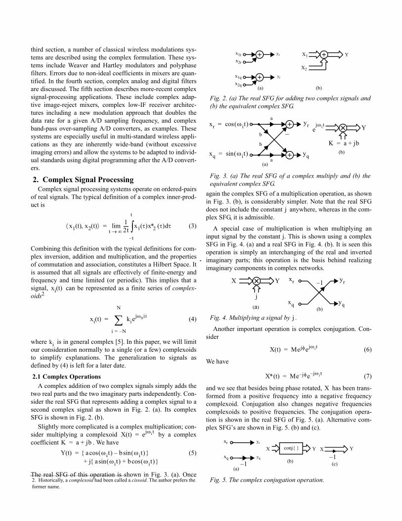
2.1 Complex OperationsA complex addition of two complex signals simply adds the
two real parts and the two imaginary parts independently. Con-sider the real SFG that represents adding a complex signal to a second complex signal as shown in Fig. 2. (a). Its complex SFG is shown in Fig. 2. (b).
Slightly more complicated is a complex multiplication; con-sider multiplying a complexoid by a complex coefficient . We have
(5)
The real SFG of this operation is shown in Fig. 3. (a). Once
again the complex SFG of a multiplication operation, as shown in Fig. 3. (b), is considerably simpler. Note that the real SFG does not include the constant anywhere, whereas in the com-plex SFG, it is admissible.
A special case of multiplication is when multiplying an input signal by the constant j. This is shown using a complex SFG in Fig. 4. (a) and a real SFG in Fig. 4. (b). It is seen this operation is simply an interchanging of the real and inverted imaginary parts; this operation is the basis behind realizing imaginary components in complex networks.
Another important operation is complex conjugation. Con-sider
(6)
We have
(7)
and we see that besides being phase rotated, has been trans-formed from a positive frequency into a negative frequency complexoid. Conjugation also changes negative frequencies complexoids to positive frequencies. The conjugation opera-tion is shown in the real SFG of Fig. 5. (a). Alternative com-plex SFG’s are shown in Fig. 5. (b) and (c).
2. Historically, a complexoid had been called a cissoid. The author prefers the former name.
x1 t( ) x2 t( ),⟨ ⟩ 12t----- x1 τ( )x∗2 τ( ) τd
t–
t
∫t ∞→lim=
xi t( )
xi t( ) kiejω0it
i N–=
N
∑=
ki
X t( ) ejωi t=K a jb+=Y t( ) a ωit( )cos b ωit( )sin–{ }
j a ωit( )sin b ωit( )cos+{ }+=
Fig. 2. (a) The real SFG for adding two complex signals and (b) the equivalent complex SFG.
Fig. 3. (a) The real SFG of a complex multiply and (b) the equivalent complex SFG.
Fig. 4. Multiplying a signal by .
Fig. 5. The complex conjugation operation.
x1rx2r
x1qx2q
yr
yr
X1
X2
Y
(a) (b)
xr ωit( )cos=
xq ωit( )sin=
yr
yq
ejωi t
K a jb+=
Y
(a)
(b)
a
a
b
b
j
xr
xq
yr
yq
X
j
Y
(a) (b)
1–
j
X t( ) Mejφejωi t=
X∗ t( ) Me jφ– e jωi t–=
X
xr yr
X Y
(a)(b)
xq yq 1–X Y
(c)1–
conj{ }
Two additional operations are required for realizing com-plex filters, namely the delay operator for digital filters and the integration operator for analog filters. These operations simply consist of independently applying the real operation to each part of the complex signal as shown in Fig. 6.
2.2 Polar to Rectangular ConversionComplex signals at a single frequency, possibly positive,
possibly negative, or possibly both, can be expressed in either polar or rectangular form. In polar form we have
(8)
where and are possibly complex coefficients. Alterna-tively, we can express in rectangular form as
(9)
It is straight-forward to show , are related to , using the duality
(10)
and
(11)
This duality, along with some simple trigometric identities, are useful in quantifying many of the imaging non-idealities.
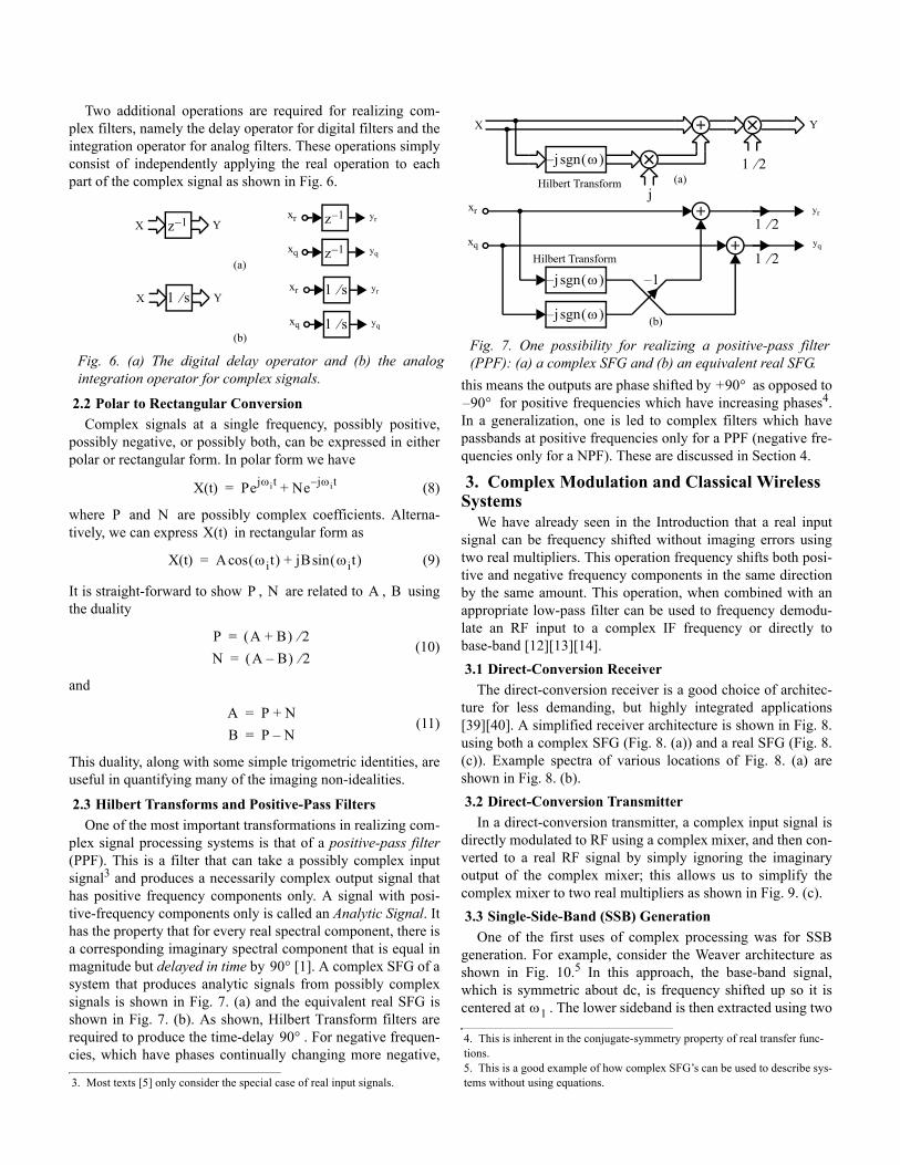
2.3 Hilbert Transforms and Positive-Pass FiltersOne of the most important transformations in realizing com-
plex signal processing systems is that of a positive-pass filter(PPF). This is a filter that can take a possibly complex input signal3 and produces a necessarily complex output signal that has positive frequency components only. A signal with posi-tive-frequency components only is called an Analytic Signal. It has the property that for every real spectral component, there is a corresponding imaginary spectral component that is equal in magnitude but delayed in time by [1]. A complex SFG of a system that produces analytic signals from possibly complex signals is shown in Fig. 7. (a) and the equivalent real SFG is shown in Fig. 7. (b). As shown, Hilbert Transform filters are required to produce the time-delay . For negative frequen-cies, which have phases continually changing more negative,
this means the outputs are phase shifted by as opposed to for positive frequencies which have increasing phases4.
In a generalization, one is led to complex filters which have passbands at positive frequencies only for a PPF (negative fre-quencies only for a NPF). These are discussed in Section 4.
3. Complex Modulation and Classical Wireless Systems
We have already seen in the Introduction that a real input signal can be frequency shifted without imaging errors using two real multipliers. This operation frequency shifts both posi-tive and negative frequency components in the same direction by the same amount. This operation, when combined with an appropriate low-pass filter can be used to frequency demodu-late an RF input to a complex IF frequency or directly to base-band [12][13][14]. 3.1 Direct-Conversion Receiver
The direct-conversion receiver is a good choice of architec-ture for less demanding, but highly integrated applications [39][40]. A simplified receiver architecture is shown in Fig. 8.using both a complex SFG (Fig. 8. (a)) and a real SFG (Fig. 8.(c)). Example spectra of various locations of Fig. 8. (a) are shown in Fig. 8. (b). 3.2 Direct-Conversion Transmitter
In a direct-conversion transmitter, a complex input signal is directly modulated to RF using a complex mixer, and then con-verted to a real RF signal by simply ignoring the imaginary output of the complex mixer; this allows us to simplify the complex mixer to two real multipliers as shown in Fig. 9. (c). 3.3 Single-Side-Band (SSB) Generation
One of the first uses of complex processing was for SSB generation. For example, consider the Weaver architecture as shown in Fig. 10.5 In this approach, the base-band signal, which is symmetric about dc, is frequency shifted up so it is centered at . The lower sideband is then extracted using two
Fig. 6. (a) The digital delay operator and (b) the analog integration operator for complex signals.
3. Most texts [5] only consider the special case of real input signals.
xr yrX Y
(a)xq yq
z 1–
1 s⁄
z 1–
z 1–
xr yrX Y
(b)xq yq1 s⁄
1 s⁄
X t( ) Pejωi t Ne jωi t–+=
P NX t( )
X t( ) A ωit( )cos jB ωit( )sin+=
P N A B
P A B+( ) 2⁄=N A B–( ) 2⁄=
A P N+=B P N–=
90°
90°
Fig. 7. One possibility for realizing a positive-pass filter (PPF): (a) a complex SFG and (b) an equivalent real SFG.
4. This is inherent in the conjugate-symmetry property of real transfer func-tions.5. This is a good example of how complex SFG’s can be used to describe sys-tems without using equations.
X Y
(b)
j ω( )sgn–
j
1 2⁄(a)
j ω( )sgn–
j ω( )sgn–
1 2⁄
1 2⁄
xr yr
yq
1–
Hilbert Transform
Hilbert Transformxq
+90°90– °
ω1
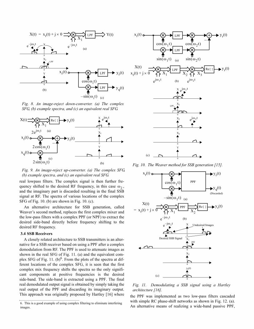
real lowpass filters. The complex signal is then further fre-quency shifted to the desired RF frequency, in this case , and the imaginary part is discarded resulting in the final SSB signal at RF. The spectra of various locations of the complex SFG of Fig. 10. (b) are shown in Fig. 10. (c).
An alternative architecture for SSB generation, called Weaver’s second method, replaces the first complex mixer and the low-pass filters with a complex PPF (or NPF) to extract the desired side-band directly before frequency shifting to the desired RF frequency. 3.4 SSB Receivers
A closely related architecture to SSB transmitters is an alter-native for a SSB receiver based on using a PPF after a complex demodulation from RF. The PPF is used to attenuate images as shown in the real SFG of Fig. 11. (a) and the equivalent com-plex SFG of Fig. 11. (b)6. From the plots of the spectra at dif-ferent locations of the complex SFG, it is seen that the first complex mix frequency shifts the spectra so the only signifi-cant components at positive frequencies is the desired side-band. The side-band is extracted using a PPF. The final real demodulated output signal is obtained by simply taking the real output of the PPF and discarding its imaginary output. This approach was originally proposed by Hartley [16] where the PPF was implemented as two low-pass filters cascaded
with simple RC phase-shift networks as shown in Fig. 12. (a). An alternative means of realizing a wide-band passive PPF,
Fig. 8. An image-reject down-converter. (a) The complex SFG, (b) example spectra, and (c) an equivalent real SFG.
Fig. 9. An image-reject up-converter. (a) The complex SFG, (b) example spectra, and (c) an equivalent real SFG.
6. This is a good example of using complex filtering to eliminate interfering images.
X t( ) xr t( ) j 0×+=
e jωi t–
Y t( )LPF
0
X
0
X1
0
Y
X1
e jωi t–
LPF
(a)
LPF
ωit( )cos
ωit( )sin–
yq t( )
yr t( )
(c)
xr t( )
LPF(b)
X t( )
2ejωi t0
X
0
X1
0
Y
X1
ejωi t
(a)
2 ωit( )cos
2 ωit( )sin
yr t( )
(c)
xr t( )
(b)
Re{ }
xq t( )
yr t( )
ω2
Fig. 10. The Weaver method for SSB generation [15].
Fig. 11. Demodulating a SSB signal using a Hartley architecture [16].
LPF
ω1t( )cos
ω1t( )sin
yr t( )
(a)
xr t( )
LPF
ω2t( )cos
ω2t( )sin
X t( )xr t( ) j 0×+
ejω1t
LPFX1
(b)
Re{ }
ejω2t
yr t( )X2 X3
0
X
0
X1
0
X2
ejω1t
(c)
LPF
ejω2t
0
X3
0
Y
ω1t( )cos
ω1t( )sin–
yr t( )
(a)
xr t( )
X t( )xr t( ) j 0×+=
e j– ω1t
PPFX1
(b)
Re{ } yr t( )X2
0
X
0
X1
0
X2
e j– ω1t
(c)
Desired SSB Signal
0
yr(t)
PPF
yq t( )
Undesired Images
(Discarded)
PPF
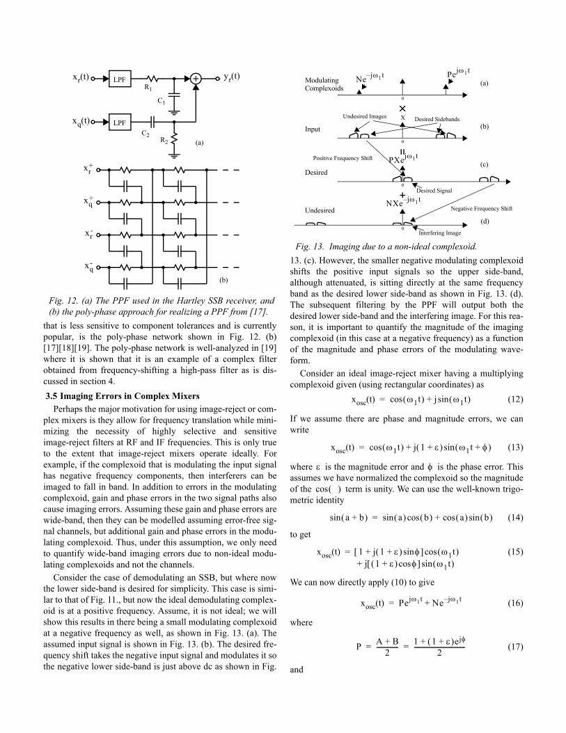
that is less sensitive to component tolerances and is currently popular, is the poly-phase network shown in Fig. 12. (b) [17][18][19]. The poly-phase network is well-analyzed in [19]where it is shown that it is an example of a complex filter obtained from frequency-shifting a high-pass filter as is dis-cussed in section 4. 3.5 Imaging Errors in Complex Mixers
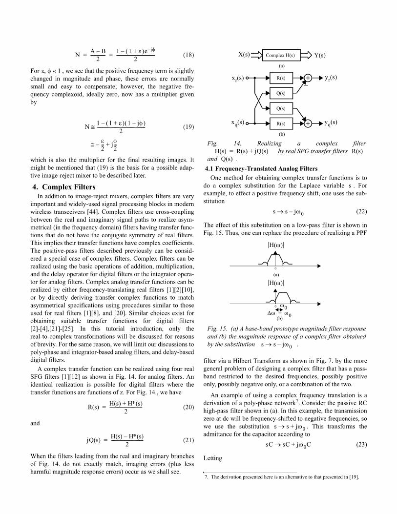
Perhaps the major motivation for using image-reject or com-plex mixers is they allow for frequency translation while mini-mizing the necessity of highly selective and sensitive image-reject filters at RF and IF frequencies. This is only true to the extent that image-reject mixers operate ideally. For example, if the complexoid that is modulating the input signal has negative frequency components, then interferers can be imaged to fall in band. In addition to errors in the modulating complexoid, gain and phase errors in the two signal paths also cause imaging errors. Assuming these gain and phase errors are wide-band, then they can be modelled assuming error-free sig-nal channels, but additional gain and phase errors in the modu-lating complexoid. Thus, under this assumption, we only need to quantify wide-band imaging errors due to non-ideal modu-lating complexoids and not the channels.
Consider the case of demodulating an SSB, but where now the lower side-band is desired for simplicity. This case is simi-lar to that of Fig. 11., but now the ideal demodulating complex-oid is at a positive frequency. Assume, it is not ideal; we will show this results in there being a small modulating complexoid at a negative frequency as well, as shown in Fig. 13. (a). The assumed input signal is shown in Fig. 13. (b). The desired fre-quency shift takes the negative input signal and modulates it so the negative lower side-band is just above dc as shown in Fig.
13. (c). However, the smaller negative modulating complexoid shifts the positive input signals so the upper side-band, although attenuated, is sitting directly at the same frequency band as the desired lower side-band as shown in Fig. 13. (d). The subsequent filtering by the PPF will output both the desired lower side-band and the interfering image. For this rea-son, it is important to quantify the magnitude of the imaging complexoid (in this case at a negative frequency) as a function of the magnitude and phase errors of the modulating wave-form.
Consider an ideal image-reject mixer having a multiplying complexoid given (using rectangular coordinates) as
(12)
If we assume there are phase and magnitude errors, we can write
(13)
where is the magnitude error and is the phase error. This assumes we have normalized the complexoid so the magnitude of the term is unity. We can use the well-known trigo-metric identity
(14)
to get
(15)
We can now directly apply (10) to give
(16)
where
(17)
and
Fig. 12. (a) The PPF used in the Hartley SSB receiver, and (b) the poly-phase approach for realizing a PPF from [17].
LPF yr t( )xr t( )
LPFxq t( )
R1
C1
C2R2
xr+
xr-
xq+
xq-
(a)
(b)
Fig. 13. Imaging due to a non-ideal complexoid.
0
Pejω1t
0
X Desired Sidebands
Ne j– ω1t
Undesired Images
0
PXejω1tPositive Frequency Shift
0
NXe j– ω1tNegative Frequency Shift
Interfering Image
Desired
Undesired
Input
ModulatingComplexoids
(a)
(b)
(c)
(d)
Desired Signal
xosc t( ) ω1t( )cos j ω1t( )sin+=
xosc t( ) ω1t( )cos j 1 ε+( ) ω1t φ+( )sin+=
ε φ
( )cos
a b+( )sin a( )sin b( )cos a( )cos b( )sin+=
xosc t( ) 1 j 1 ε+( ) φsin+[ ] ω1t( )cosj 1 ε+( ) φcos[ ] ω1t( )sin+
=
xosc t( ) Pejω1t Ne j– ω1t+=
P A B+2
-------------- 1 1 ε+( )ejφ+2
---------------------------------= =
(18)
For , we see that the positive frequency term is slightly changed in magnitude and phase, these errors are normally small and easy to compensate; however, the negative fre-quency complexoid, ideally zero, now has a multiplier given by
(19)
which is also the multiplier for the final resulting images. It might be mentioned that (19) is the basis for a possible adap-tive image-reject mixer to be described later.
4. Complex FiltersIn addition to image-reject mixers, complex filters are very
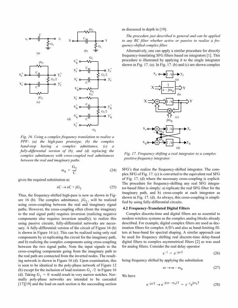
important and widely-used signal processing blocks in modern wireless transceivers [44]. Complex filters use cross-coupling between the real and imaginary signal paths to realize asym-metrical (in the frequency domain) filters having transfer func-tions that do not have the conjugate symmetry of real filters. This implies their transfer functions have complex coefficients. The positive-pass filters described previously can be consid-ered a special case of complex filters. Complex filters can be realized using the basic operations of addition, multiplication, and the delay operator for digital filters or the integrator opera-tor for analog filters. Complex analog transfer functions can be realized by either frequency-translating real filters [1][2][10], or by directly deriving transfer complex functions to match asymmetrical specifications using procedures similar to those used for real filters [1][8], and [20]. Similar choices exist for obtaining suitable transfer functions for digital filters [2]-[4],[21]-[25]. In this tutorial introduction, only the real-to-complex transformations will be discussed for reasons of brevity. For the same reason, we will limit our discussions to poly-phase and integrator-based analog filters, and delay-based digital filters.
A complex transfer function can be realized using four real SFG filters [1][12] as shown in Fig. 14. for analog filters. An identical realization is possible for digital filters where the transfer functions are functions of z. For Fig. 14., we have
(20)
and
(21)
When the filters leading from the real and imaginary branches of Fig. 14. do not exactly match, imaging errors (plus less harmful magnitude response errors) occur as we shall see.
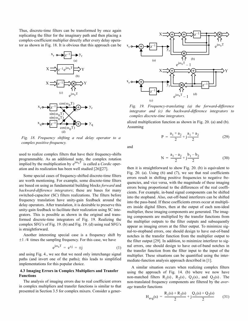
4.1 Frequency-Translated Analog FiltersOne method for obtaining complex transfer functions is to
do a complex substitution for the Laplace variable . For example, to effect a positive frequency shift, one uses the sub-stitution
(22)
The effect of this substitution on a low-pass filter is shown in Fig. 15. Thus, one can replace the procedure of realizing a PPF
filter via a Hilbert Transform as shown in Fig. 7. by the more general problem of designing a complex filter that has a pass-band restricted to the desired frequencies, possibly positive only, possibly negative only, or a combination of the two.
An example of using a complex frequency translation is a derivation of a poly-phase network7. Consider the passive RC high-pass filter shown in (a). In this example, the transmission zero at dc will be frequency-shifted to negative frequencies, so we use the substitution . This transforms the admittance for the capacitor according to
(23)
Letting
N A B–2
-------------- 1 1 ε+( )e j– φ–2
------------------------------------= =
ε φ, 1«
N 1 1 ε+( ) 1 jφ–( )–2
---------------------------------------------
ε2---– jφ
2---+≅
≅
R s( ) H s( ) H∗ s( )+2
------------------------------=
jQ s( ) H s( ) H∗ s( )–2
------------------------------=
Fig. 14. Realizing a complex filter by real SFG transfer filters
and .
Fig. 15. (a) A base-band prototype magnitude filter response and (b) the magnitude response of a complex filter obtained by the substitution .
7. The derivation presented here is an alternative to that presented in [19].
Complex H(s)X s( ) Y s( )
R(s)
Q(s)
Q(s)
R(s)
xr s( )
xq s( )
yr s( )
yq s( )
(a)
(b)
H s( ) R s( ) jQ s( )+= R s( )Q s( )
s
s s jω0–→
0
H ω( )
0
H ω( )
ω0∆ω ω0=
(a)
(b)
s s jω0–→
s s jω0+→
sC sC jω0C+→
(24)
gives the required substitution as
(25)
Thus, the frequency-shifted high-pass is now as shown in Fig-ure 16 (b). The complex admittance, , will be realized using cross-coupling between the real and imaginary signal paths. However, the cross-coupling often (from the imaginary to the real signal path) requires inversion (realizing negative components also requires inversion usually); to realize this using passive circuits, fully-differential networks are neces-sary. A fully-differential version of the circuit of Figure 16 (b) is shown in Figure 16 (c). This can be realized using only real components by a) replicating the circuit for the imaginary path, and b) realizing the complex components using cross-coupling between the two signal paths. Note the input signals to the cross-coupling components going from the imaginary path to the real path are connected from the inverted nodes. The result-ing network is shown in Figure 16 (d). Upon examination, this is seen to be identical to the poly-phase network of Figure 12(b) except for the inclusion of load resistors in Figure 16(d). Taking would result in very narrow notches. Nor-mally poly-phase networks are intended to be cascaded [17][19] and the load on each section is the succeeding section
as discussed in depth in [19].
The procedure just described is general and can be applied to any RC filter whether active or passive to realize a fre-quency-shifted complex filter.
Alternatively, one can apply a similar procedure for directly frequency-translating SFG filters based on integrators [1]. This procedure is illustrated by applying it to the single integrator shown in Fig. 17. (a). In Fig. 17. (b) and (c) are shown complex
SFG’s that realize the frequency-shifted integrator. The com-plex SFG of Fig. 17. (c) is converted to the equivalent real SFG of Fig. 17. (d) where the necessary cross-coupling is explicit. The procedure for frequency-shifting any real SFG integra-tor-based filter is simply: a) replicate the real SFG filter for the imaginary path, and b) cross-couple at each integrator as shown in Fig. 17. (d). As always, this cross-coupling is simpli-fied by using fully-differential circuits. 4.2 Frequency-Translated Digital Filters
Complex discrete-time and digital filters are as essential to modern wireless systems as the complex analog blocks already described. For example, digital complex filters are used as dec-imation filters for complex A/D’s and also as band-limiting fil-ters at base-band for spectral shaping. A similar approach can be used for frequency shifting real discrete-time delay-based digital filters to complex asymmetrical filters [2] as was used for analog filters. Consider the real delay operator
(26)
being frequency shifted by applying the substitution
(27)
We have
(28)
Fig. 16. Using a complex frequency translation to realize a PPF: (a) the high-pass prototype, (b) the complex band-stop having a complex admittance, (c) a fully-differential version of (b), and (d) replacing the complex admittances with cross-coupled real admittances between the real and imaginary paths.
xr
G1
C
G1
yr X Y
C
jG2
C
G1/2
jG2
C
xr+
xr-
yr+
yr-
C
G2
C
G2
xr+
xr-
yr+
yr-
xq+
xq-
C
G2
C
G2
xq+
xq-
yq+
yq-
xr+
xr-
(a)(b)
(c)
(d)
G1/2
G1/2
jG2
ω0G2C------=
sC sC jG2+→
jG2
G1 2⁄G1 0=
Fig. 17. Frequency shifting a real integrator to a complex positive-frequency integrator.
xr 1 s⁄ yr
(b)
1s jω0–-----------------X Y
1 s⁄
jω0
X Y
(c)
1 s⁄
1 s⁄
ω0
ω0
xr
xq
yr
yq(d)
(a)
z 1– e jωT–=
ω ω ω0–→
e jωT– e j ω ω0–( )T–→ z 1– ejω0T=
Thus, discrete-time filters can be transformed by once again replicating the filter for the imaginary path and then placing a complex-coefficient multiplier directly after every delay opera-tor as shown in Fig. 18. It is obvious that this approach can be
used to realize complex filters that have their frequency-shifts programmable. As an additional note, the complex rotation implied by the multiplication by is called a Cordic oper-ation and its realization has been well studied [26][27].
Some special cases of frequency-shifted discrete-time filters are worth mentioning. For example, some discrete-time filters are based on using as fundamental building blocks forward and backward-difference integrators; these are bases for many switched-capacitor (SC) filters realizations. The filters before frequency translation have unity-gain feedback around the delay operators. After translation, it is desirable to preserve this unity-gain feedback to facilitate their realization using SC inte-grators. This is possible as shown in the original and trans-formed discrete-time integrators of Fig. 19. Realizing the complex SFG’s of Fig. 19. (b) and Fig. 19. (d) using real SFG’s is straightforward.
Another interesting special case is a frequency shift by times the sampling frequency. For this case, we have
(1)and using Fig. 4., we see that we need only interchange signal paths (and invert one of the paths); this leads to simplified implementations for this popular choice.
4.3 Imaging Errors in Complex Multipliers and Transfer Functions
The analysis of imaging errors due to real coefficient errors in complex multipliers and transfer functions is similar to that presented in Section 3.5 for complex mixers. Consider a gener-
alized multiplication function as shown in Fig. 20. (a) and (b). Assuming
(29)
and
(30)
then it is straightforward to show Fig. 20. (b) is equivalent to Fig. 20. (a). Using (6) and (7), we see that real coefficients errors result in shifting positive frequencies to negative fre-quencies, and vice versa, with the magnitude of these imaging errors being proportional to the differences of the real coeffi-cients. For example, in-band signal components can be shifted into the stopband. Also, out-off-band interferers can be shifted into the pass-band. If these coefficients errors occur at multipli-ers inside digital filters, then at the output of each non-ideal multiplier, these imaging components are generated. The imag-ing components are multiplied by the transfer functions from the multiplier outputs to the filter outputs and subsequently appear as imaging errors at the filter output. To minimize sig-nal-to-stopband errors, one should design to have out-of-band notches in the transfer function from the multiplier output to the filter output [29]. In addition, to minimize interferer to sig-nal errors, one should design to have out-of-band notches in the transfer function from the filter input to the input of the multiplier. These situations can be quantified using the inter-mediate-function analysis approach described in [1].
A similar situation occurs when realizing complex filters using the approach of Fig. 14. (b) where we now have non-matched filters , , , and . The non-translated frequency components are filtered by the aver-age transfer functions
(31)
Fig. 18. Frequency shifting a real delay operator to a complex positive-frequency.
xr z 1– yr
(b)
z 1– ejω0TX Y
X Y
xr
xq
yr
yq
(a)
z 1–
ejω0T(c)
z 1–
z 1–
ω0T( )sinω0T( )sin
ω0T( )cos
ω0T( )cos(d)
ejω0T
1 4⁄±
ejω0T e j± j±= =
Fig. 19. Frequency-translating (a) the forward-differenceintegrator and (c) the backward-difference integrators tocomplex discrete-time integrators.
xr z 1–yr
X
(a)
ejω0T
(b)
z 1–
ejω0T 1–
xr
z 1–
yr
(c)
z 1–
ejω0T 1–
X
Y
(d)
Pa1 a2+
2---------------- j
a1 a2+2
----------------+=
Na1 a2–
2---------------- j
b1 b2–2
-----------------+=
R1 s( ) R2 s( ) Q1 s( ) Q2 s( )
Havg s( )R1 s( ) R2 s( )+
2-------------------------------- j
Q1 s( ) Q2 s( )+2
--------------------------------+=
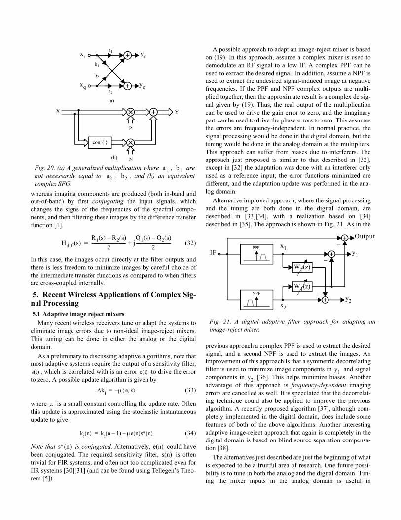
whereas imaging components are produced (both in-band and out-of-band) by first conjugating the input signals, which changes the signs of the frequencies of the spectral compo-nents, and then filtering these images by the difference transfer function [1].
(32)
In this case, the images occur directly at the filter outputs and there is less freedom to minimize images by careful choice of the intermediate transfer functions as compared to when filters are cross-coupled internally.
5. Recent Wireless Applications of Complex Sig-nal Processing 5.1 Adaptive image reject mixers
Many recent wireless receivers tune or adapt the systems to eliminate image errors due to non-ideal image-reject mixers. This tuning can be done in either the analog or the digital domain.
As a preliminary to discussing adaptive algorithms, note that most adaptive systems require the output of a sensitivity filter,
, which is correlated with is an error to drive the error to zero. A possible update algorithm is given by
(33)
where is a small constant controlling the update rate. Often this update is approximated using the stochastic instantaneous update to give
(34)
Note that is conjugated. Alternatively, could have been conjugated. The required sensitivity filter, is often trivial for FIR systems, and often not too complicated even for IIR systems [30][31] (and can be found using Tellegen’s Theo-rem [5]).
A possible approach to adapt an image-reject mixer is based on (19). In this approach, assume a complex mixer is used to demodulate an RF signal to a low IF. A complex PPF can be used to extract the desired signal. In addition, assume a NPF is used to extract the undesired signal-induced image at negative frequencies. If the PPF and NPF complex outputs are multi-plied together, then the approximate result is a complex dc sig-nal given by (19). Thus, the real output of the multiplication can be used to drive the gain error to zero, and the imaginary part can be used to drive the phase errors to zero. This assumes the errors are frequency-independent. In normal practice, the signal processing would be done in the digital domain, but the tuning would be done in the analog domain at the multipliers. This approach can suffer from biases due to interferers. The approach just proposed is similar to that described in [32], except in [32] the adaptation was done with an interferer only used as a reference input, the error functions minimized are different, and the adaptation update was performed in the ana-log domain.
Alternative improved approach, where the signal processing and the tuning are both done in the digital domain, are described in [33][34], with a realization based on [34]described in [35]. The approach is shown in Fig. 21. As in the
previous approach a complex PPF is used to extract the desired signal, and a second NPF is used to extract the images. An improvement of this approach is that a symmetric decorrelating filter is used to minimize image components in and signal components in [36]. This helps minimize biases. Another advantage of this approach is frequency-dependent imaging errors are cancelled as well. It is speculated that the decorrelat-ing technique could also be applied to improve the previous algorithm. A recently proposed algorithm [37], although com-pletely implemented in the digital domain, does include some features of both of the above algorithms. Another interesting adaptive image-reject approach that again is completely in the digital domain is based on blind source separation compensa-tion [38].
The alternatives just described are just the beginning of what is expected to be a fruitful area of research. One future possi-bility is to tune in both the analog and the digital domain. Tun-ing the mixer inputs in the analog domain is useful in
Fig. 20. (a) A generalized multiplication where , are not necessarily equal to , , and (b) an equivalent complex SFG.
xr
xq
yr
yq
(b)
a1
a2
b1
b2
X Y
conj{ }
P
N
(a)
a1 b1a2 b2
Hdiff s( )R1 s( ) R2 s( )–
2------------------------------- j
Q1 s( ) Q2 s( )–2
--------------------------------+=
s t( ) e t( )
∆ki µ e s,⟨ ⟩–=
µ
ki n( ) ki n 1–( ) µe n( )s∗ n( )–=
s∗ n( ) e n( )s n( )
Fig. 21. A digital adaptive filter approach for adapting an image-reject mixer.
PPF
NPF
W2 z( )
W1 z( )
x1
x2
y1
y2
Output
IF
y1y2
preventing overload in the IF stages and to help attain timing acquisition, but is only useful for correcting frequency-inde-pendent errors. A second adaptive fine-tuning in the digital domain similar to [34] can be used to further eliminate fre-quency-dependent errors of, for-example, complex over-sam-pling A/D’s used at the IF. 5.2 Low-IF Receivers.
A currently popular architecture for realizing highly-inte-grated moderately wide-band wireless transceivers is the low-IF architecture [41][42][43]. An example of a low-IF receiver is shown in Fig. 22. In a low-IF receiver, the RF signal
is demodulated in two stages; the first stage is a standard image-reject mixer which requires two analog real multipliers. This translates the RF input signal down to a low-IF frequency, after which a second complex mixer is used to shift the IF sig-nal to base-band. The second complex mixer requires four real multipliers. These can be realized using analog multipliers as in [42]. Alternatively, the A/D conversion can be done at the IF stage as shown in Fig. 22., and then the second complex fre-quency shift can be realized in the digital domain [43]. This allows the second complex modulation to be almost ideal. Also, if the A/D sampling frequency is chosen to be a small multiple of the IF frequency, then the second mix is signifi-cantly simplified. For example, if the sampling frequency is four times the IF frequency, then the oscillator inputs to the second complex digital mixer are or 0. This digital modula-tion alternative is often preferable.
Low-IF architectures are especially suitable for multi-stan-dard receivers when the channel-selection filters are realized after the A/D converters using digital circuits, and, thus, can be programmed to accommodate the requirements of the different standards. The low-IF architectures greatly minimize errors due to feedback of the local-oscillator (LO) and the large 1/f noise of MOS transistors. They do suffer from images when the IF frequency is low, but these can be significantly mini-mized by using even relatively simple complex filters at the IF [44].
In general, when the A/D conversion occurs before the channel-selection filters, then the A/D conversion must neces-sarily be high dynamic range, and the A/D converter is almost always the limiting factor determining the maximum achiev-able data rate of the receiver. Assuming the A/D converter is the limiting factor on the maximum achievable data rate, then
it is possible to double the maximum-achievable data rate using the modulation approach proposed in [45]. A typical low-IF architecture has IF spectral components at positive or negative frequencies only; this wastes half the available band-width of the A/D’s8. It is possible to send additional data in the unused frequency band. In the simplest implementation, one channel is implemented at positive frequencies and one chan-nel is implemented at negative frequencies; in more-advanced realizations, multiple channels are implemented at both posi-tive and negative frequencies using orthogonal-frequency-divi-sion-multiplexing (OFDM) techniques. In both cases the physical hardware is the same as for typical low-IF receivers (as shown in Fig. 22.); the increase in complexity is all in the digital domain and is quite feasible.
The approach for single channels only at positive and nega-tive frequencies is shown in Fig. 23. At the transmitter, two
quadrature input channels are used; one is modulated to posi-tive frequencies, and one is modulated to negative frequencies. A guard-band is left at dc. The congregate is modulated up to the RF and transmitted. This approach is much like a double single-side-band system where both an upper and a lower side-band are transmitted together. At the receiver, the RF sig-nal is demodulated so one channel is again at a positive IF and the second channel is at a negative IF. The guard-band at dc allows the IF signal to be ac coupled which eliminates errors due to the local feedback of the RF oscillator and 1/f noise. The IF signal is then digitized similar to a typical low-IF architec-ture. After the A/D conversion, the individual channels can be
Fig. 22. A low-IF architecture for a receiver.
0o
90o LO1
LNA
PreselectionFilter
ADC
ADC
DSP
−
ωot( )cos
ωot( )cos
ωot( )sin
1±
8. This assumes the A/D converters are not complex over-sampling A/D’s; if they are, the bandwidth is not necessarily wasted. This is one of the motiva-tions for using complex over-sampling A/D’s.
Fig. 23. A Hierarchical Modulation approach to achieve twice the data rate for a given sampling rate of the A/D’s.
ej2πf0t
e-j2πf0t
f0
-f0
ej2πfCt
fCfC-fC
Re{ }.
fC-fC
e-j2πfCt
-2fC
e-j2πf0t
ej2πf0t
f0
f0-f0
Modulator:
Demodulator:
TrnF
TrnF
RcvF
RcvF
0
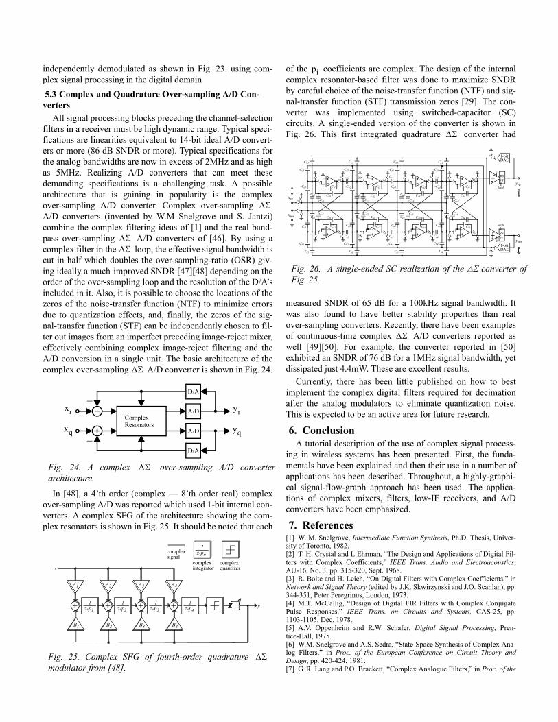
f
independently demodulated as shown in Fig. 23. using com-plex signal processing in the digital domain 5.3 Complex and Quadrature Over-sampling A/D Con-verters
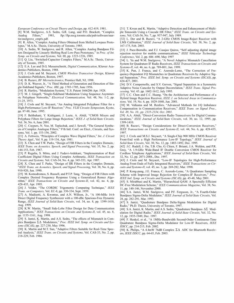
All signal processing blocks preceding the channel-selection filters in a receiver must be high dynamic range. Typical speci-fications are linearities equivalent to 14-bit ideal A/D convert-ers or more (86 dB SNDR or more). Typical specifications for the analog bandwidths are now in excess of 2MHz and as high as 5MHz. Realizing A/D converters that can meet these demanding specifications is a challenging task. A possible architecture that is gaining in popularity is the complex over-sampling A/D converter. Complex over-sampling A/D converters (invented by W.M Snelgrove and S. Jantzi) combine the complex filtering ideas of [1] and the real band-pass over-sampling A/D converters of [46]. By using a complex filter in the loop, the effective signal bandwidth is cut in half which doubles the over-sampling-ratio (OSR) giv-ing ideally a much-improved SNDR [47][48] depending on the order of the over-sampling loop and the resolution of the D/A’s included in it. Also, it is possible to choose the locations of the zeros of the noise-transfer function (NTF) to minimize errors due to quantization effects, and, finally, the zeros of the sig-nal-transfer function (STF) can be independently chosen to fil-ter out images from an imperfect preceding image-reject mixer, effectively combining complex image-reject filtering and the A/D conversion in a single unit. The basic architecture of the complex over-sampling A/D converter is shown in Fig. 24.
In [48], a 4’th order (complex — 8’th order real) complex over-sampling A/D was reported which used 1-bit internal con-verters. A complex SFG of the architecture showing the com-plex resonators is shown in Fig. 25. It should be noted that each
of the coefficients are complex. The design of the internal complex resonator-based filter was done to maximize SNDR by careful choice of the noise-transfer function (NTF) and sig-nal-transfer function (STF) transmission zeros [29]. The con-verter was implemented using switched-capacitor (SC) circuits. A single-ended version of the converter is shown in Fig. 26. This first integrated quadrature converter had
measured SNDR of 65 dB for a 100kHz signal bandwidth. It was also found to have better stability properties than real over-sampling converters. Recently, there have been examples of continuous-time complex A/D converters reported as well [49][50]. For example, the converter reported in [50]exhibited an SNDR of 76 dB for a 1MHz signal bandwidth, yet dissipated just 4.4mW. These are excellent results.
Currently, there has been little published on how to best implement the complex digital filters required for decimation after the analog modulators to eliminate quantization noise. This is expected to be an active area for future research.
6. ConclusionA tutorial description of the use of complex signal process-
ing in wireless systems has been presented. First, the funda-mentals have been explained and then their use in a number of applications has been described. Throughout, a highly-graphi-cal signal-flow-graph approach has been used. The applica-tions of complex mixers, filters, low-IF receivers, and A/D converters have been emphasized.
7. References[1] W. M. Snelgrove, Intermediate Function Synthesis, Ph.D. Thesis, Univer-sity of Toronto, 1982.[2] T. H. Crystal and L Ehrman, “The Design and Applications of Digital Fil-ters with Complex Coefficients,” IEEE Trans. Audio and Electroacoustics, AU-16, No. 3, pp. 315-320, Sept. 1968.[3] R. Boite and H. Leich, “On Digital Filters with Complex Coefficients,” in Network and Signal Theory (edited by J.K. Skwirzynski and J.O. Scanlan), pp. 344-351, Peter Peregrinus, London, 1973.[4] M.T. McCallig, “Design of Digital FIR Filters with Complex Conjugate Pulse Responses,” IEEE Trans. on Circuits and Systems, CAS-25, pp. 1103-1105, Dec. 1978.[5] A.V. Oppenheim and R.W. Schafer, Digital Signal Processing, Pren-tice-Hall, 1975.[6] W.M. Snelgrove and A.S. Sedra, “State-Space Synthesis of Complex Ana-log Filters,” in Proc. of the European Conference on Circuit Theory and Design, pp. 420-424, 1981.[7] G. R. Lang and P.O. Brackett, “Complex Analogue Filters,” in Proc. of the
Fig. 24. A complex over-sampling A/D converter architecture.
Fig. 25. Complex SFG of fourth-order quadrature modulator from [48].
∆Σ
∆Σ∆Σ
∆Σ
ComplexResonators
A/D
A/D
D/A
D/A
yr
yq
xr
xq
∆Σ
1z-p1
1z-p4
y
x
1z-pn
A4A3A2A1
B1 B2 B3 B4
complexsignal
complexquantizer
complexintegrator
1z-p2
1z-p3
z 1–
∆Σ
Fig. 26. A single-ended SC realization of the ∆Σ converter oFig. 25.
pi
∆Σ
RSFF
1-bitDAC
12d
Ci1
Cc1Cd1
Cb1
12d
1 22d 1
1 22d 1
1 22d 1
1 22d 1
1 22d 1
1 22d 1
122d1
21
12d
21
21
Cx2
Ca1
Cf1
Ce1
Ci2
Cc2Cd2
Cb2
Cx3
Ca2
Cf2
Ce2
Ci3
Cc3Cd3
Cb3
Cx4
Ca3
Cf3
Ce3
Ci4
Cc4Cd4
Cb4
Ca4
Cf4
Ce4
Ci1
-Cc1
Cd1
-Cf1
Cx2
-Ce1
Cb1
Ca1
Ci2
-Cc2
Cd2
-Cf2
Cx3
-Ce2
Cb2
Ca2
Ci3
-Cc3
Cd3
-Cf3
Cx4
-Ce3
Cb3
Ca3
Ci4
-Cc4
Cd4
-Cf4
-Ce4
Cb4
Ca4
1-bitDAC
2
RSFF
2
latch
latch
xim
xre
yre
yim
∆Σ
European Conference on Circuit Theory and Design, pp. 412-419, 1981.[8] W.M. Snelgrove, A.S. Sedra, G.R. Lang, and P.O. Brackett, “Complex Analog Filters,” 1981, ftp://ftp.eecg.toronto.edu/pub/software/mar-tin/snelgrove_cmplx.pdf.[9] R. Allen, “Complex Analog Filters Obtained from Shifted Lowpass Proto-types,” M.A.Sc. Thesis, University of Toronto, 1985.[10] A. Sedra, W. Snelgrove, and R. Allen, “Complex Analog Bandpass Fil-ters Designed by Linearly Shifting Real Low-Pass Prototypes,” in Proc. of Int. Symp. on Circuits and Systems, Vol. III, pp. 1223-1226, 1985.[11] Q. Liu, “Switched-Capacitor Complex Filters,” M.A.Sc. Thesis, Univer-sity of Toronto, 1985.[12] E.A. Lee and D.G. Messerschmitt, Digital Communication, Kluwer Aca-demics Publishers, Boston, 1988.[13] J. Crols and M. Steyaert, CMOS Wireless Transceiver Design, Kluwer Academics Publishers, Boston, 1997.[14] B. Razavi, RF Microelectronics, Prentice Hall, NJ, 1998.[15] D. K. Weaver, Jr., “A Third Method of Generation and Detection of Sin-gle-Sideband Signals,” Proc. IRE, pp. 1703-1705, June 1956.[16] R. Hartley, “Modulation System,” U.S. Patent 1666206 Apr. 1928.[17] M. J. Gingell, “Single-Sideband Modulation Using Sequence Asymmet-ric Polyphase Networks,” Electrical Communication, Vol. 48, No. 1-2, pp. 21-25, 1973.[18] J. Crols and M. Steyaert, “An Analog Integrated Polyphase Filter for a High-Performance Low-IF Receiver,” Proc. VLSI Circuits Symposium, Kyoto, pp. 87-88, June. 1995.[19] F. Behbahani, Y. Kishigami, J. Leete, A. Abidi, “CMOS Mixers and Polyphase Filters for Large Image Rejection,” IEEE J. of Solid-State Circuits,Vol. 36, No. 6, June 2001.[20] C. Cuypers, N. Voo, M. Teplechuk, and J. Sewell, “The General Synthe-sis of Complex Analogue Filters,” 9’th Intl. Conf. on Elect., Circuits, and Sys-tems, Vol. 1, pp. 153-156, 2002.[21] A. Fettweis, “Principles of Complex Wave Digital Filters,” Int. J. Circuit Theory Appl., Vol. 9, pp. 119-134, Apr. 1981.[22] X. Chen and T.W. Parks, “Design of FIR Filters in the Complex Domain,: IEEE Trans. on Acoustics, Speech, and Signal Processing, Vol. 35, No. 2, pp. 144-153, Feb. 1987.[23] P. Regalia, S. Mitra, and J. Fadavi-Ardekani, “Implementation of Real Coefficient Digital Filters Using Complex Arithmetic, IEEE Transaction on Circuits and Systems, Vol. CAS-34, No. 4, pp. 345-353, Apr. 1987.[24] X. Chen and T. Parks, “Design of IIR Filters in the Complex Domain, “IEEE Trans. on Acoustics, Speech, and Signal Processing, Vol. 38, No. 6, pp. 910-920, Jun. 1990.[25] M. Komodromos, S. Russell, and P.T.P. Tang, “Design of FIR Filters with Complex Desired Frequency Response Using a Generalized Remez Algo-rithm,” IEEE Transactions on Circuits and Systems-II, vol. 42, no. 4, pp. 428-435, Apr. 1995.[26] J. Volder, “The CORDIC Trigometric Computing Technique,” IEEE Trans. on Computers, Vol. EC-8, pp. 330-334, Sept. 1959.[27] A. Madisetti, A. Kwentus, and A.N. Willson, Jr., “A 100-MHz 16-b Direct Digital Frequency Synthesizer with a 100-dBc Spurious-Free Dynamic Range, IEEE Journal of Solid-State Circuits, vol. 34, no. 8, pp. 1399-1410, Aug. 1999.[28] K.W. Martin, “Small Side-Lobe Filter Design for Data Communication Applications,” IEEE Transactions on Circuits and Systems-II, vol. 45, no. 8, pp. 1155-1161, Aug. 1998.[29] S. Jantzi, K. Martin, and A.S. Sedra, “The effects of Mismatch in Com-plex Bandpass Modulators,” Proc. IEEE Intl. Symp. on Circuits and Sys-tems (ISCAS), pp. 227-230, May 1996.[30] K. Martin and M.T. Sun, “Adaptive Filters Suitable for Real-Time Spec-tral Analysis,” IEEE Trans. on Circuits and Systems, Vol. CAS-33, No. 2, pp. 218-229, Feb. 1986.
[31] T. Kwan and K. Martin, “Adaptive Detection and Enhancement of Multi-ple Sinusoids Using a Cascade IIR Filter,” IEEE Trans. on Circuits and Sys-tems, Vol. CAS-36, No. 7, pp. 937-947, July 1989.[32] L. Der and B. Razavi, “A 2-GHz CMOS Image-Reject Receiver with LMS Calibration,” IEEE Journal of Solid-State Circuits, Vol. 38, No. 2, pp. 167-175, Feb. 2003.[33] J. Paez-Borrallo, and F.J. Casajus Quiros, “Self adjusting digital image rejection receiver for mobile communications,” IEEE Vehicular Technology Conference, Vol. 2, pp. 686 -690, May 1997[34] L. Yu and W.M. Snelgrove, “A Novel Adaptive Mismatch Cancellation System for Quadrature IF Radio Receivers, IEEE Transactions on Circuits and Systems-II, vol. 46, no. 6, pp. 789-801, Jun. 1999.[35] K. Pun, J. Franca, and C. Azeredo-Leme, “The Correction of Fre-quency-Dependent I/Q Mismatches in Quadrature Receivers by Adaptive Sig-nal Separation,” Proc. IEEE Intl. Symp. on Circuits and Systems (ISCAS), pp. 424-427, 2001.[36] D.V. Compernolle, and S.V. Gerven, “Signal Separation in a Symmetric Adaptive Noise Canceler by Output Decorrelation,” IEEE Trans. Signal Pro-cessing, Vol. 43. pp. 1602-1612, July 1995.[37] C.C. Chen and C.C. Huang, “On the Architecture and Performance of a Hybrid Image Rejection Receiver, IEEE J. on Selected Areas in Communica-tions, Vol. 19, No. 6, pp. 1029-1040, Jun. 2001.[38] M. Valkama and M. Renfors, “Advanced Methods for I/Q Imbalance Compensation in Communication Receivers,” IEEE Trans. on Signal Proc., Vol. 49, No. 10., pp. 2335-2334, Oct. 2001.[39] A.A. Abidi, “Direct-Conversion Radio Transceivers for Digital Commu-nications,” IEEE Journal of Solid-State Circuits, vol. 30, no. 12, 1995, pp. 1399-1410.[40] B. Razavi, “Design Considerations for Direct-Conversion Receivers,” IEEE Transactions on Circuits and Systems-II, vol. 44, No. 6, pp. 428-435, 1997.[41] J. Crols and M.S.J. Steyaert, “A Single-Chip 900 MHz CMOS Receiver Front-End with a High Performance Low-IF Topology,” IEEE Journal of Solid-State Circuits, Vol. 30, No. 12, pp. 1483-1492, Dec. 1995.[42] J.C. Rudell, J. Ou, T.B. Cho, G. Chien, F. Brianti, J.A. Weldon, and P.R. Gray, “A 1.9-GHz Wide-Band IF Double Conversion CMOS Receiver for Cordless Telephone Applications,” IEEE Journal of Solid-State Circuits, Vol. 32, No. 12, pp. 2071-2088., Dec. 1997.[43] J. Crols and M. Steyaert, “Low-IF Topologies for High-Performance Analog Front Ends of Fully Integrated Receivers,” IEEE Transactions on Cir-cuits and Systems-II, vol. 45, no. 3, pp. 269-282, Mar. 1998.[44] P. Kong-pang, J.E. Franca, C. Azeredo-Leme, “A Quadrature Sampling Scheme with Improved Image Rejection for Complex-IF Receivers,” Proc. IEEE Intl. Symp. on Circuits and Systems (ISCAS), pp. 45-48, May 2001.[45] S. Mirabbasi and K. Martin, “Hierarchical QAM: A Spectrally Efficient DC-Free Modulation Scheme,” IEEE Communications Magazine, Vol. 38, No. 11, pp. 140-146, November 2000.[46] S.A. Jantzi, W.M. Snelgrove, and P.F. Ferguson, Jr., “A Fourth-Order Bandpass Sigma-Delta Modulator,” IEEE Journal of Solid-State Circuits, Vol. 28, pp. 282-291, Mar. 1993.[47] S. Jantzi, “Quadrature Bandpass Delta-Sigma Modulation for Digital Radio,” Ph.D. Thesis, University of Toronto, 1997.[48] S.A. Jantzi, K. Martin, and A.S. Sedra, “Quadrature Bandpass Mod-ulation for Digital Radio,” IEEE Journal of Solid-State Circuits, Vol. 32, No. 12, pp. 1935-1949, Dec. 1997.[49] F. Henkel, et al., “A 1MHz-Bandwidth Second-Order Continuous-Time Quadrature Bandpass Sigma-Delta Modulator for Low-IF Receivers, IEEE ISSCC, pp. 214-215, Feb. 2002.[50] K. Philips, “A 4.4mW 76dB Complex ADC for Bluetooth Receiv-ers, IEEE ISSCC, pp. 64-65, Feb. 2003.
Σ∆
∆Σ
Σ∆