compliance document for ventilation – third edition · pdf filedocuments are available...
TRANSCRIPT

This Compliance Document is prepared by the Department of Building and Housing. The Department of Building and Housing is a Government Department established under the State Sector Act 1988.
Enquiries about the content of this document should be directed to:
Department of Building and Housing PO Box 10-729, Wellington. Telephone 0800 242 243 Fax 04 471 0798, Email: [email protected]
Sales enquiries should be directed to:Customer Services,Victoria University Book CentrePO Box 12-337, Wellington, New ZealandTelephone 0800 370 370, (04) 463 5511Fax (04) 463 5510Email: [email protected] 0-477-01606-5
© Department of Building and Housing 2008
This Compliance Document is protected by Crown copyright, unless indicated otherwise. The Department of Building and Housing administers the copyright in this document. You may use and reproduce this document for your personal use or for the purposes of your business provided you reproduce the document accurately and not in an inappropriate or misleading context. You may not distribute this document to others or reproduce it for sale or profit.
The Department of Building and Housing owns or has licences to use all images and trademarks in this document. You must not use or reproduce images and trademarks featured in this document for any purpose (except as part of an accurate reproduction of this document) unless you first obtain the written permission of the Department of Building and Housing.
Compliance Document for New Zealand Building Code Clause G4 Ventilation – Third EditionPrepared by the Department of Building and Housing
ARCHIVED
Document Status
The most recent version of this document, as detailed in the Document History, is approved by the Chief Executive of the Department of Building and Housing. It is effective from 1 November 2008 and supersedes all previous versions of this document.
People using this Compliance Document should check for amendments on a regular basis. The Department of Building and Housing may amend any part of any Compliance Document at any time. Up-to-date versions of Compliance Documents are available from www.dbh.govt.nz
Status of Compliance Documents
Compliance Documents are prepared by the Department of Building and Housing in accordance with section 22 of the Building Act 2004. A Compliance Document is for use in establishing compliance with the New Zealand Building Code.
A person who complies with a Compliance Document will be treated as having complied with the provisions of the Building Code to which the Compliance Document relates. However, a Compliance Document is only one method of complying with the Building Code. There may be alternative ways to comply.
Users should make themselves familiar with the preface to the New Zealand Building Code Handbook, which describes the status of Compliance Documents and explains alternative methods of achieving compliance.
Defined words (italicised in the text) and classified uses are explained in Clauses A1 and A2 of the Building Code and in the Definitions at the start of this Compliance Document.
G4: Document History
Date Alterations
First published July 1992
Amendment 1 September 1993 p. 3, 1.1.2
ReprintedincorporatingAmendment 1
July 1994
Second edition 28 February 1998 Document revised – second edition issued
Amendment 1 23 June 2007 p. 2, Document History, Status p.5, Contents p.7, References
p.9, Definitions pp. 13–16 G4/AS1
Third edition 1 November 2008 Document revised – third edition issued
Note: Page numbers relate to the document at the time of Amendment and may not match page numbers in current document.
ARCHIVED

New Zealand Building Code Clause G4 VentilationThis Clause is extracted from the New Zealand Building Code contained in the First Schedule of the Building Regulations 1992 and amended by the Building Amendment Regulations 1997.
FIRST SCHEDULE–continued
Clause G4–VENTILATION
Provisions
ObjECTIVEG4.1Theobjectiveofthisprovisionistosafeguardpeoplefromillnessorlossofamenityduetolackoffreshair.
FUNCTIONAL REqUIREmENTG4.2Spaceswithinbuildingsshallbeprovidedwithadequateventilationconsistentwiththeirmaximumoccupancyandtheirintendeduse.
PERFORmANCEG4.3.1Spaceswithinbuildingsshallhavemeansofventilationwithoutdoor airthatwillprovideanadequatenumberofairchangestomaintainairpurity.
G4.3.2Mechanicalair-handlingsystemsshallbeconstructedandmaintainedinamannerthatpreventsharmfulbacteria,pathogensandallergensfrommultiplyingwithinthem.
G4.3.3Buildingsshallhaveameansofcollectingorotherwiseremovingthefollowingproductsfromthespacesinwhichtheyaregenerated:
(a)Cookingfumesandodours,
(b)Moisturefromlaundering,utensilwashing,bathingandshowering,
(c) Odoursfromsanitaryandwastestoragespaces,
(d)Gaseousby-productsandexcessivemoisturefromcommercialorindustrialprocesses,
(e) Poisonousfumesandgases,
(f) Flammablefumesandgases,
(g)Airborneparticles,
(h)Bacteria,virusesorotherpathogens,or
(i) Productsofcombustion.
Limits on application
D E P A R T m E N T O F B U I l D I N G A N D H O U S I N G 1 N o v e m b e r 2 0 0 8
V E N T I L A T I O NClause G4
�
ARCHIVED
V E N T I L A T I O N Clause G4
1 N o v e m b e r 2 0 0 8 D E P A R T m E N T O F B U I l D I N G A N D H O U S I N G��
FIRST SCHEDULE–continued
Provisions
G4.3.4Contaminatedairshallbedisposedofinawaywhichavoidscreatinganuisanceorhazardtopeopleandother property.
G4.3.5Thequantitiesofairsuppliedforventilationshallmeettheadditionaldemandsofanyfixedcombustion appliances.
Limits on application
ARCHIVED
D E P A R T m E N T O F B U I l D I N G A N D H O U S I N G
V E N T I L A T I O NContents G4/VM1 & AS1
�1 N o v e m b e r 2 0 0 8
Contents Page
References 7
Definitions 9
Verification Method G4/VM1 11
1.0 Ventilation Rate 11
2.0 Air Purity 11
Acceptable Solution G4/AS1 13
1.0 Ventilation 13
1.1 Introduction 13
1.2 Natural ventilation – General 13
1.3 Natural ventilation of both household 13 units and accommodation units with one external wall
1.4 Combined natural ventilation and 17 mechanical ventilation
1.5 mechanical ventilation 18
2.0 Ventilation of Spaces Containing Gas-fuel Appliances 19
2.1 Natural ventilation 19
2.2 mechanical ventilation 19
2.3 Flue construction 19
2.4 Flue locations on dwellings 20
3.0 Another Solution for Gas-fuel Appliances 20
Appendix 1 Typical apartment layouts 21 and ventilation options
Index 25
ARCHIVED

�
ARCHIVED
ReferencesFor the purposes of New Zealand Building Code compliance, the New Zealand and other Standards, and other documents referred to in this Compliance Document (primary reference documents) shall be the editions, along with their specific amendments, listed below. Where the primary reference documents refer to other Standards or other documents (secondary reference documents), which in turn may also refer to other Standards or other documents, and so on (lower order reference documents), then the applicable version of these secondary and lower order reference documents shall be the version in effect at the date this Compliance Document was published.
Where quoted
Standards New Zealand
AS/NZS 3666:– Air-handling and water systems of buildings – microbial control Part 1: 2002 Design, installation and commissioning AS1 1.5.1 b) Part 2: 2002 Operation and maintenance AS1 1.5.1 b)
NZS 4303: 1990 Ventilation for acceptable indoor air quality AS1 1.5.1 a) d)
AS/NZS 4740: 2000 Natural ventilators – Classification and performance AS1 1.3.7 c)
NZS 5261: 2003 The installation of gas burning appliances and AS1 2.3.1 b), 2.4.1 c), equipment 3.0.1
Standards Australia
AS 1668:– The use of mechanical ventilation and air-conditioning in buildings Part 2: 2002 Ventilation design for indoor-air contaminant control AS1 1.2.4, 1.3.7 d) 1.5.1 a) c) i) ii) d) e), f), g),
New Zealand Government Departments
Department of labour (Occupational Safety and Health) Workplace Vm1 2.0.1 exposure standards and biological exposure indices for New Zealand 1992
Chartered Institution of Building Services Engineers, London
CIBSE Code Series A: 1996 Air distribution systems Vm1 1.0.1, AS1 1.5.1 h)
D E P A R T m E N T O F B U I l D I N G A N D H O U S I N G
V E N T I L A T I O NReferences G4/VM1 & AS1
�1 N o v e m b e r 2 0 0 8
ARCHIVED

1 N o v e m b e r 2 0 0 8�
ARCHIVED
D E P A R T m E N T O F B U I l D I N G A N D H O U S I N G
V E N T I L A T I O NDef in i t ions G4/VM1 & AS1
�1 N o v e m b e r 2 0 0 8
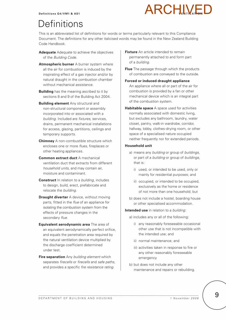
DefinitionsThis is an abbreviated list of definitions for words or terms particularly relevant to this Compliance Document. The definitions for any other italicised words may be found in the New Zealand Building Code Handbook.
Adequate Adequate to achieve the objectives of the Building Code.
Atmospheric burner A burner system where all the air for combustion is induced by the inspirating effect of a gas injector and/or by natural draught in the combustion chamber without mechanical assistance.
Building has the meaning ascribed to it by sections 8 and 9 of the Building Act 2004.
Building element Any structural and non-structural component or assembly incorporated into or associated with a building. Included are fixtures, services, drains, permanent mechanical installations for access, glazing, partitions, ceilings and temporary supports.
Chimney A non-combustible structure which encloses one or more flues, fireplaces or other heating appliances.
Common extract duct A mechanical ventilation duct that extracts from different household units, and may contain air, moisture and contaminant.
Construct In relation to a building, includes to design, build, erect, prefabricate and relocate the building.
Draught diverter A device, without moving parts, fitted in the flue of an appliance for isolating the combustion system from the effects of pressure changes in the secondary flue.
Equivalent aerodynamic area The area of an equivalent aerodynamically perfect orifice, and equals the penetration area required by the natural ventilation device multiplied by the discharge coefficient determined under test.
Fire separation Any building element which separates firecells or firecells and safe paths, and provides a specific fire resistance rating.
Fixture An article intended to remain permanently attached to and form part of a building.
Flue The passage through which the products of combustion are conveyed to the outside.
Forced or induced draught appliance An appliance where all or part of the air for combustion is provided by a fan or other mechanical device which is an integral part of the combustion system.
Habitable space A space used for activities normally associated with domestic living, but excludes any bathroom, laundry, water closet, pantry, walk-in wardrobe, corridor, hallway, lobby, clothes-drying room, or other space of a specialised nature occupied neither frequently nor for extended periods.
Household unit
a) means any building or group of buildings, or part of a building or group of buildings, that is:
i) used, or intended to be used, only or mainly for residential purposes; and
ii) occupied, or intended to be occupied, exclusively as the home or residence of not more than one household; but
b) does not include a hostel, boarding house or other specialised accommodation.
Intended use in relation to a building:
a) includes any or all of the following:
i) any reasonably foreseeable occasional other use that is not incompatible with the intended use; and
ii) normal maintenance; and
iii) activities taken in response to fire or any other reasonably foreseeable emergency
b) but does not include any other maintenance and repairs or rebuilding.
ARCHIVED

V E N T I L A T I O N Def in i t ions G4/VM1 & AS1
D E P A R T m E N T O F B U I l D I N G A N D H O U S I N G10
1 N o v e m b e r 2 0 0 810
Natural draught The flow produced by the tendency of warmed gases to rise.
Net openable area is the area of windows or doors or other opening measured on the face dimensions of the openable building element concerned.
Occupied space Any space within a building in which a person will be present from time to time during the intended use of the building.
Outdoor air Air as typically comprising by volume:
i) oxygen 20.94%
ii) carbon dioxide 0.03%
iii) nitrogen and other inert gases 79.03%.
Passive stack ventilator A system including a ventilation shaft which uses natural draught to ventilate spaces.
Permanent opening An opening which cannot be closed, this implies that doors, windows etc are NOT permanent openings, although door undercuts are.
Room-sealed appliance An appliance designed so that air for combustion neither enters from, nor combustion products enter into, the room in which the appliance is located.
Trickle ventilator A controllable ventilation opening through the external envelope to the outside to provide background ventilation.
ARCHIVED
D E P A R T m E N T O F B U I l D I N G A N D H O U S I N G
V E N T I L A T I O NV er i f i cat ion Method G4/VM1
111 N o v e m b e r 2 0 0 8
Verification method G4/Vm11.0 Ventilation Rate
1.0.1 In ducted mechanical ventilation systems the air-flow rate (and consequently number of air changes), may be verified using the methods of measurement given in the CIBSE Code Series A, Appendix A3.1. For determining the volume of outdoor air, measurements shall be taken close to the outdoor air inlet.
2.0 Air Purity
2.0.1 The acceptability of indoor air purity for workplaces may be verified by demonstrating that contaminant levels do not exceed the limits recommended in “Workplace Exposure Standards and Biological Exposure Indices for New Zealand 1992”.
ARCHIVED

1 N o v e m b e r 2 0 0 81212
ARCHIVED

D E P A R T m E N T O F B U I l D I N G A N D H O U S I N G 1 N o v e m b e r 2 0 0 8
V E N T I L A T I O NAcceptab le So lut ion G4/AS1
1�
Acceptable Solution G4/AS11.0 Ventilation
1.1 Introduction
1.1.1 Ventilation of spaces within buildings is required to maintain air purity by a flow of outdoor air through the building envelope, with or without mechanical assistance.
1.1.2 Ventilation of spaces within buildings must be provided by natural ventilation (refer to Paragraphs 1.2 and 1.3), mechanical ventilation (refer to Paragraph 1.5), or a combination of mechanical and natural ventilation (refer to Paragraph 1.4).
1.1.3 Buildings containing Type 5 fire alarm systems must have mechanical extract ventilation installed in kitchens.
1.2 Natural ventilation – General
1.2.1 Where natural ventilation is available via adjacent spaces, specific ventilation is not required to small spaces such as hallways and lobbies in household units.
1.2.2 Natural ventilation of occupied spaces must be achieved by providing a net openable area of windows or other openings to the outside of no less than 5% of the floor area. The 5% floor area requirement does not apply to:
a) occupied spaces in Commercial and Industrial buildings where products listed in NZBC Clause G4.3.3 are generated (mechanical ventilation of these spaces is required), and
b) household units and accommodation units where there is only one external wall with opening windows (refer to Paragraph 1.3 for additional requirements if natural ventilation is used).
1.2.3 Openable building elements shall be constructed in a way that allows them to remain fixed in the open position as a means of ventilation during normal occupancy of the building.
1.2.4 Natural ventilation of car parks shall comply with the natural ventilation part of AS 1668.2 Section 7.
1.3 Natural ventilation of household units and accommodation units with one external wall
Scope
1.3.1 Paragraphs 1.3.2 to 1.3.9 specify the natural ventilation to both household units and accommodation units with only one external wall, such as those often found in apartments, hotels and motels.
Kitchens, bathrooms, toilets and laundries that have an external wall
1.3.2 For kitchens, bathrooms, toilets and laundries located on the external wall, moisture and other contaminants must be ventilated to the outside by natural ventilation using either:
a) windows and/or other openings to the outside with a net openable area of no less than 5% of the floor area, or
b) high level trickle ventilators located through the external wall or building elements within the external wall (see Paragraph 1.3.9 for trickle ventilators ), where the distance between the external wall and opposing wall is less than 6 metres.
COMMENT: If activities or environmental conditions adjacent to external natural ventilation openings produce air pollution in any of the forms listed in NZBC G4.3.3, it may be necessary to relocate the openings or use mechanical ventilation.
COMMENT: Refer to Compliance Documents F7 Warning Systems F7/AS1 and C Fire Safety C/AS1 Appendix A for information on Type 5 fire alarms.
COMMENT: 1. The net openable area of windows or doors is
measured on the face dimensions of the building element concerned.
2. Fixing in an open position of doors and windows used for ventilation is necessary to avoid injury or damage from sudden closure in the event of strong winds or other forces.
3. Keeping water from entering the building must be considered for compliance with NZBC Clause E2 External moisture.
ARCHIVED

V E N T I L A T I O N Acceptab le So lut ion G4/AS1
1 N o v e m b e r 2 0 0 8 D E P A R T m E N T O F B U I l D I N G A N D H O U S I N G1�
Kitchens, bathrooms, toilets and laundries without an external wall
1.3.3 For kitchens, bathrooms, toilets and laundries not located on the external wall, moisture and other contaminants must be ventilated to the outside by natural ventilation having:
a) a passive stack ventilator, located in the kitchen, bathroom, toilet or laundry, designed to extract a continuous airflow through the surrounding habitable spaces (see Paragraph 1.3.7 for passive stack ventilators ), and
b) high level trickle ventilators, located within the external wall or in building elements that are integrated within the external wall (see Paragraph 1.3.9 for trickle ventilators ), and
c) permanent openings for airflow between the surrounding habitable spaces and the kitchen, bathroom, toilet or laundry of no less than 5% of the combined floor area of the spaces, and not compromising the privacy of the toilet or bathroom, and
d) a combined distance of the habitable space and the kitchen, bathroom, toilet or laundry measured between the external wall and furthest opposing wall of less than 10 metres.
Habitable spaces that have an external wall and open to a kitchen, bathroom, toilet or laundry with a passive stack ventilator
1.3.4 For habitable spaces with both an external wall and a permanent opening to a kitchen, bathroom, toilet or laundry, ventilation shall be achieved by:
a) installing high level trickle ventilators, located within the external wall or building elements within the external wall (see Paragraph 1.3.9 for trickle ventilators ), and
b) having a passive stack ventilator installed in the kitchen, bathroom, toilet or laundry, and
c) having an area of permanent opening between the two spaces of no less than 5% of the combined floor area of the habitable space and the kitchen, bathroom, toilet or laundry, and not compromising the privacy of the toilet or bathroom, and
d) windows and/or other openings to the outside with an net openable area of no less than 5% of the floor area, and
e) having a maximum dimension between the external wall and the furthest internal opposing wall, when measured across the combined habitable space and the kitchen, bathroom, toilet, or laundry, of less than 10 metres.
Habitable spaces that have an external wall and do not open to a kitchen, bathroom, toilet or laundry with a passive stack ventilator
1.3.5 For habitable spaces with an external wall and no permanent opening to surrounding spaces, ventilation must be achieved by having:
a) windows and/or other openings to the outside with an net openable area of no less than 5% of the floor area, and
b) high level trickle ventilators, located within the external wall or in building elements within the external wall (see Paragraph 1.3.9 for trickle ventilators ), and
c) a distance between the external wall and opposing wall of the habitable spaces of less than 6 metres.
Habitable spaces ventilated via another habitable space
1.3.6 Ventilation of a habitable space without openings to the exterior via another habitable space must be achieved by:
a) providing from the other habitable space to outside, openable windows and/or other openings of net openable area of no less than 5% of the combined floor area of the combined habitable spaces, and
ARCHIVED

D E P A R T m E N T O F B U I l D I N G A N D H O U S I N G 1 N o v e m b e r 2 0 0 8
V E N T I L A T I O NAcceptab le So lut ion G4/AS1
1�
b) providing high and low level trickle ventilators located on the external wall (see Paragraph 1.3.9 for trickle ventilators ), sized according to the combined floor area, and
c) providing an area of permanent opening between the two spaces of no less than 5% of the combined floor area of the habitable spaces, and
d) having a combined distance of the habitable spaces, measured between the external wall and furthest opposing wall, of less than 6 metres.
Passive stack ventilators
1.3.7 Passive stack ventilators consist of a vertical ventilation shaft which uses air buoyancy to ventilate spaces. Passive stack ventilators shall:
a) have no connections from spaces other than kitchens connecting to the kitchen passive stack ventilator, and
b) not be used in household units in combination with mechanical ventilation systems, and
c) be designed in accordance with AS/NZS 4740 Section 3, and
d) be designed to achieve extract airflow rates specified in AS 1668.2 Table B1, using the following parameters:
Air Density r = 1.2 kg/m³ Gravitational Constant g = 9.81 m/s² Temperature Differential DT = 3K Outside Ambient Temperature T = 300K Wind Velocity Vt = 0m/s, and
e) be integrated into the building without decreasing the performance of the building envelope and the partition walls of the building for external moisture, fire and acoustics, and
f) be capable of drawing air through trickle ventilators or permanent openings from the room or adjacent spaces. The permanent openings to the surrounding spaces and trickle ventilators to the outside shall have an equivalent aerodynamic area greater than the equivalent aerodynamic area of the passive stack ventilator. This is to ensure air can be drawn through the passive stack ventilator effectively.
g) when extracting from kitchens:
i) maintain the fire separation of the fire separated shaft with a pressure-forming intumescent fire collar around a collapsible duct, and
ii) have ducting, downstream of the fire collar, made of non-combustible material, and
iii) have connections that contain no more than two bends and do not have any duct that is more than 45° to the vertical, and
Figure 1: Fire Shunt System Paragraph 1.3.7
ARCHIVED
V E N T I L A T I O N Acceptab le So lut ion G4/AS1
1 N o v e m b e r 2 0 0 8 D E P A R T m E N T O F B U I l D I N G A N D H O U S I N G1�
iv) have the branch connection to the common duct via a fire shunt of 1800 mm in height (see Figure 1), and
v) have the fire shunt and the stack located in a fire separated shaft.
h) when extracting from bathrooms, toilets and laundries:
i) be installed in a fire separated shaft, and ii) have the branch connection to the common extract duct via a fire shunt of 900 mm in height (see Figure 1), and
iii) have connections that contain no more than two bends and do not have any duct that is more than 45° to the vertical, and
iv) be ducting made of non-combustible material, unless the common extract duct is the only duct in the fire separated shaft.
i) have ventilation ducts and stacks that are insulated in any unheated areas with a minimum thickness of 25 mm of a material having a thermal conductivity of no less than 0.04W/m2K, and
j) have a condensation trap fitted to the part of the duct above the roof level.
1.3.8 The terminal of a passive stack ventilator shall:
a) have an equivalent aerodynamic area greater than the cross-sectional area of the stack, and
b) extend above the roof to at least the ridge height.
Trickle ventilators
1.3.9 Trickle ventilators are devices that have an opening to the outside. Trickle ventilators shall:
a) have an opening of no less than 2000 mm2 equivalent aerodynamic area, and
b) be located to minimise draughts, and
c) be secured to keep pests and insects out, and
d) have acoustic attenuation, if required by NZBC G6 Airborne and Impact Sound, and
e) be controllable and closable in all conditioned spaces, and
f) be installed in household units, providing they do not contain mechanical supply ventilation, and
g) have the sum of the equivalent aerodynamic area greater than the sum of the equivalent area of the passive stack ventilator(s), if installed in a household unit, and
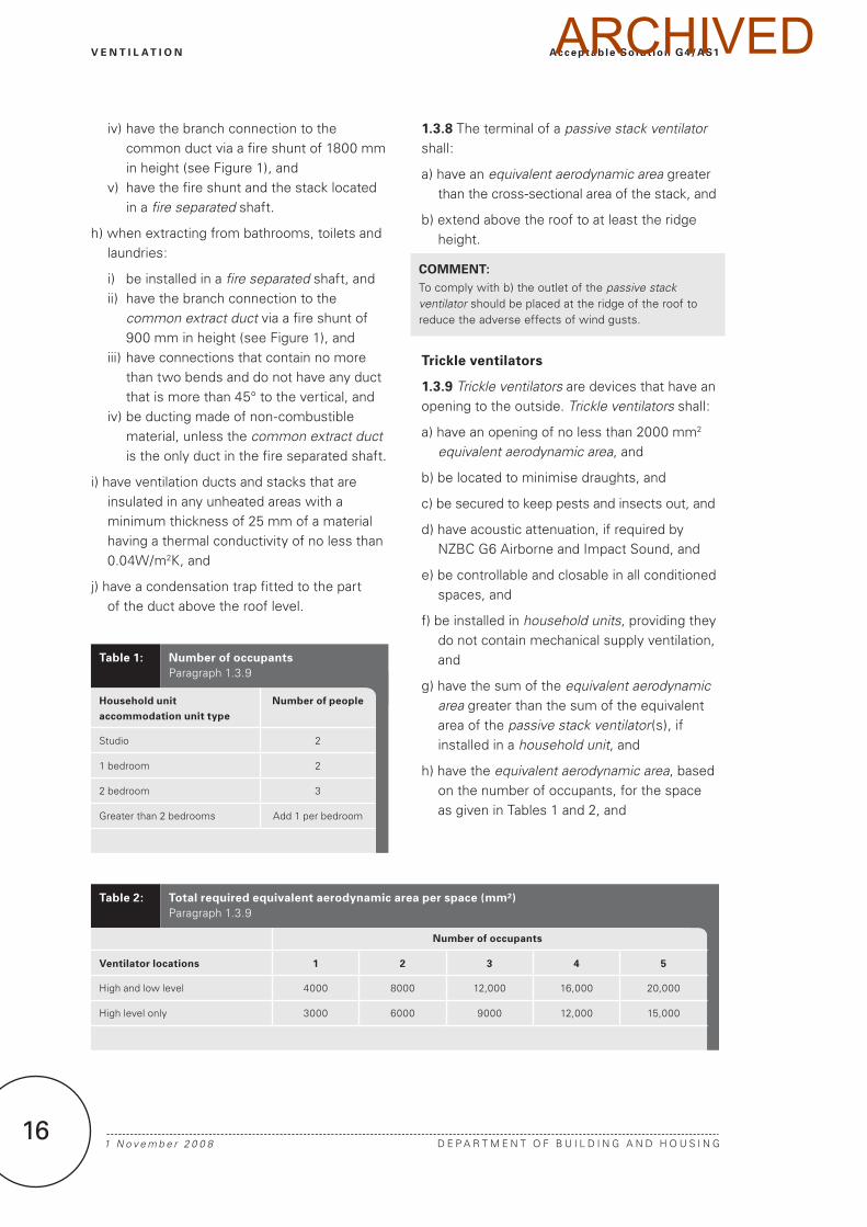
h) have the equivalent aerodynamic area, based on the number of occupants, for the space as given in Tables 1 and 2, and
COMMENT: To comply with b) the outlet of the passive stack ventilator should be placed at the ridge of the roof to reduce the adverse effects of wind gusts.
Table 2: Total required equivalent aerodynamic area per space (mm²)Paragraph 1.3.9
Number of occupants
Ventilator locations 1 2 3 4 5
High and low level 4000 8000 12,000 16,000 20,000
High level only 3000 6000 9000 12,000 15,000
Table 1: Number of occupantsParagraph 1.3.9
Household unit accommodation unit type
Number of people
Studio 2
1 bedroom 2
2 bedroom 3
Greater than 2 bedrooms Add 1 per bedroom
ARCHIVED
D E P A R T m E N T O F B U I l D I N G A N D H O U S I N G 1 N o v e m b e r 2 0 0 8
V E N T I L A T I O NAcceptab le So lut ion G4/AS1
1�
COMMENT: There are a range of trickle ventilators, sometime called background ventilators, on the market.
i) have, where high and low level trickle ventilators are required, the high and low level trickle ventilators of approximately the same equivalent aerodynamic area and separated by a minimum of 1 metre. High level trickle ventilators are located in the top half of the wall. low level trickle ventilators are located in the bottom half of the wall.
1.4 Combined natural ventilation and mechanical ventilation
Scope
1.4.1 This section specifies the combined natural and mechanical ventilation requirements for both household units and accommodation units, with one external wall, such as those often found in apartments, hotels and motels.
Habitable spaces will be naturally ventilated, and kitchens, bathrooms, toilets and laundries will be ventilated by continuous or intermittent mechanical extract ventilation.
Combination ventilation with continuous mechanical extract
1.4.2 For habitable spaces with both one external wall and a permanent opening to a kitchen, bathroom, toilet or laundry, within which a continuous mechanical extract system is installed, ventilation shall be achieved by:
a) integrating high level trickle ventilators, located within the external wall or building elements that are integrated within the external wall (see Paragraph 1.3.9 for trickle ventilators ), and
b) having a net openable area of windows and/or other openings to the outside of no less than 5% of the floor area, and
c) having the kitchen, bathroom, toilet, or laundry door undercut by 20 mm, and
d) having a maximum dimension between the external wall and the furthest internal opposing wall, when measured across the combined habitable space and the kitchen, bathroom, toilet, or laundry, of less than 10 metres.
Combination ventilation with intermittent mechanical extract
1.4.3 For habitable spaces with one external wall and a permanent opening to a kitchen, bathroom, laundry, or toilet, within which an intermittent mechanical extract system is installed, ventilation shall be achieved by:
a) integrating high and low level trickle ventilators, located within the external wall or building elements that are integrated within the external wall (see Paragraph 1.3.9 for trickle ventilators ), and
b) having a net openable area of windows and/or other openings to the outside of no less than 5% of the floor area, and
c) having the kitchen, bathroom, toilet, or laundry door undercut by 20 mm, and
d) having a maximum dimension between the external wall and the furthest internal opposing wall, when measured across the combined habitable space and the kitchen, bathroom, toilet, or laundry, of less than 6 metres.
COMMENT: If Paragraphs 1.4.2 and 1.4.3 both apply, then ventilation shall be achieved by complying with Paragraph 1.4.3.
ARCHIVED

V E N T I L A T I O N Acceptab le So lut ion G4/AS1
1 N o v e m b e r 2 0 0 8 D E P A R T m E N T O F B U I l D I N G A N D H O U S I N G1�
1.5 Mechanical ventilation
1.5.1 mechanical ventilation systems must satisfy the following conditions:
a) outdoor air supply shall be designed and equipment installed to comply with NZS 4303, or AS 1668.2 (excluding Table A1 and Sections 3 and 7), and to provide outdoor air to occupied spaces at the flow rates given in NZS 4303 Table 2, and
b) air-handling systems shall be installed and maintained to the requirements of AS/NZS 3666.1 and AS/NZS 3666.2, and
c) extract ventilation shall:
i) be constructed so that any products listed in Clause G4.3.3 are removed, collected or diluted by ventilation rates and methods set out in AS 1668.2 Section 5
COMMENT: Positive pressure allows good control of intake air filtration, whereas under negative pressure, unfiltered air may be drawn through gaps and openings in building elements.
COMMENT: Negative pressure reduces the likelihood of contaminants being spread to other spaces.
ii) where provided to remove moisture and other contaminants from kitchens, bathrooms, toilet spaces and laundries in household units, exhaust the air to the outside at flow rates given in AS 1668.2, Table B1, and iii) where provided for extract from kitchens, bathrooms, toilets and laundries in buildings containing household units or accommodation units, refer to Paragraphs 1.5.2 and 1.5.3.
d) outdoor air intakes shall be located to avoid contamination from any local source in accordance with AS 1668.2 Clause 4.3.1 and NZS 4303 Clause 5.5, and
e) recirculated air systems shall comply with AS 1668.2 Clause 4.5, and
f) contaminated air discharge systems shall discharge contaminated air in a way that complies with AS 1668.2 Clause 5.10, and
g) filtration shall comply with AS 1668.2 Clause 4.4, and
h) commissioning shall comply with CIBSE Code Series A.
COMMENT: Commercial kitchen extract ventilation is included in AS 1668.2 Section 5.
Extract ventilation from buildings containing household units and accommodation units
1.5.2 Extract ventilation from kitchens must:
a) maintain the fire separation of the fire separated shaft with a pressure-forming intumescent fire collar around a collapsible duct, and
b) have ducting, downstream of the fire collar, made of non-combustible material, and
c) have the branch connection to the common extract duct located in a fire separated shaft, and
d) have the fire shunt and common extract duct located in a separated shaft.
1.5.3 Extract ventilation from bathrooms, toilets and laundries must:
a) be installed in a fire separated shaft, and
b) have the branch connection to the common extract duct via a fire shunt of 900 mm in height, and
c) be ducting made of non-combustible material, unless the common extract duct is the only duct in the fire separated shaft.
Car park ventilation
1.5.4 mechanical ventilation of car parks shall comply with the mechanical ventilation part of AS 1668.2 Section 7.
Positive and negative pressure
1.5.5 Building interiors ventilated by mechanical systems incorporating filtration shall, except where Paragraph 1.4.4 applies, be maintained at a positive pressure.
1.5.6 Spaces in which mechanical ventilation is used to remove or collect contaminants shall be maintained at negative pressure relative to other spaces in the building.
ARCHIVED

D E P A R T m E N T O F B U I l D I N G A N D H O U S I N G 1 N o v e m b e r 2 0 0 8
V E N T I L A T I O NAcceptab le So lut ion G4/AS1
1�
2.0 Ventilation of Spaces Containing Gas-fuel Appliances
2.1 Natural ventilation
2.1.1 Natural ventilation systems for appliances burning gas fuel designed to operate under natural draught conditions shall:
a) Supply air under equal pressure conditions to the burners and to the draught diverter i.e. in the same room and as close as possible to the appliance, and
b) For non room-sealed appliances having a combined gas input exceeding 1 kW for each m3 of the space in which they are installed, be provided with vents, in addition to the ventilation required by Paragraphs 1.1 and 1.2. The vents shall be sized and located according to Paragraphs 2.1.3 to 2.1.8.
2.1.2 Domestic gas cookers in non room-sealed spaces which are also used for sleeping, require permanent venting to the outside. The size of the vent shall be appropriate to the gas input to the cooker and shall be subject to specific design.
2.1.3 Vent sizes
Two permanent vent openings, one high level and one low level, shall be provided, each with a free ventilation area per kW of gas input (of all appliances in the space) of no less than:
a) 1200 mm2 for spaces vented directly to the outside, and
b) 2300 mm2 for spaces vented via adjacent spaces.
2.1.4 The vent opening areas given in Paragraph 2.1.3 may be halved for plant rooms and boiler rooms infrequently occupied by people.
2.1.5 Vent openings shall have vertical dimensions of no less than 50 mm, and no dimension of less than 6.0 mm in any other direction.
2.1.6 low-level vents shall have their lower edge no more than 100 mm above floor level, and upper-level vents shall have their lower edge no less than 75 mm above the top of the draught diverter relief opening.
2.1.7 A louvred door is also an acceptable method of ventilation provided the bottom of the free area extends to not less than 100 mm above the floor, and the requisite high-level free area is available from the level of 75 mm above the draught diverter relief opening.
2.1.8 In plant room or boiler room installations, low- and high-level vents may be combined into a single opening, provided it reaches from floor to ceiling and has a total free area equivalent to that required for the two separate vents.
2.2 Mechanical ventilation
2.2.1 When mechanical ventilation is used, the system shall have either:
a) mechanical supply with mechanical extraction, or
b) mechanical supply with natural exhaust.
2.2.2 A mechanical ventilation system shall:
a) For each kW of gas consumption (of all appliances in the plant room) provide outdoor air at the rate of:
i) 3.6 m3/h for forced or induced draught appliances, and
ii) 7.2 m3/h for appliances with atmospheric burners, and
b) Remove exhaust air from the room either:
i) mechanically at one third the inlet rate, or
ii) naturally via high-level openings having a free ventilation area of no less than 600 mm2 per kW of total gas consumption for all appliances in the room.
2.3 Flue construction
2.3.1 A flue system shall have:
a) The cross-sectional area of a natural draught flue system external to the appliances, no less than the cross-sectional area of the appliance outlet, or
b) The flue designed to comply with NZS 5261 Appendix F, and
c) If a draught diverter is not fitted:
ARCHIVED
V E N T I L A T I O N Acceptab le So lut ion G4/AS1
1 N o v e m b e r 2 0 0 8 D E P A R T m E N T O F B U I l D I N G A N D H O U S I N G20
i) flue products discharged to the atmosphere only at the flue terminal, unless the discharge at other locations can be achieved without hazard to persons, property or appliance operation, and
ii) a method of automatically shutting down the main burners of forced or induced draught appliances, should the normal free discharge of the flue be interrupted.
2.3.2 Draught diverters
Draught diverter installations shall discharge the total flue products including excess air and draught diverter dilution air, at the flue terminal without spillage from the skirt of the draught diverter.
2.4 Flue locations on dwellings
2.4.1 The location of a flue terminal on a dwelling shall have:
a) Outlets from natural draught flues or chimneys, positioned relative to surrounding construction to avoid wind causing down draughts in the flue,
b) Flue pipes which extend through the roof, terminated no closer than:
i) 500 mm to the nearest part of any roof,
ii) 2.0 m to the roof level of a flat roof intended for personal or public use, and
iii) 500 mm above any parapet, and
c) Flues which terminate on the wall of a building located clear of inlets for outside air in accordance with the minimum clearances specified in NZS 5261 Figure 2.
3.0 Another Solution for Gas-fuel Appliances
3.0.1 NZS 5261 Part 2 Appendices A to H, J and l is an Acceptable Solution, but may exceed the performance criteria of NZBC G4.
ARCHIVED

D E P A R T m E N T O F B U I l D I N G A N D H O U S I N G 1 N o v e m b e r 2 0 0 8
V E N T I L A T I O NAcceptab le So lut ion G4/AS1
21
Appendix 1 Typical apartment layouts and ventilation options
Table 3: Ventilation options – Layout 1Figure 2
Room Natural ventilation (Paragraph)
Mechanical ventilation (Paragraph)
Combined ventilation (Paragraph)
Bedroom 1.3.5 1.5 –
living 1.3.4 1.5 1.4.2 (10 m max dist) or 1.4.3 (6 m max dist)
Kitchen 1.3.2 1.5 1.4.2 (10 m max dist) or 1.4.3 (6 m max dist)
Bathroom 1.3.3 1.5 1.4.2 (10 m max dist) or 1.4.3 (6 m max dist)
Figure 2: Layout 1 Table 3
External wall
Opening windows or trickle ventilators in outside wallInternal
wall
� metre max applies to Paragraphs 1.�.2, 1.�.�, and 1.�.�.10 metre max applies to Paragraphs 1.�.�, 1.�.� and 1.�.2.
� m max for Paragraph 1.�.�
ARCHIVED

V E N T I L A T I O N Acceptab le So lut ion G4/AS1
1 N o v e m b e r 2 0 0 8 D E P A R T m E N T O F B U I l D I N G A N D H O U S I N G22
Table 4: Ventilation options – Layout 2Figure 3
Room Natural ventilation (Paragraph)
Mechanical ventilation (Paragraph)
Combined ventilation (Paragraph)
Bedrooms 1.3.5 1.5 –
living 1.3.4 1.5 1.4.2 (10 m max dist) or 1.4.3 (6 m max dist)
Kitchen 1.3.3 1.5 1.4.2 (10 m max dist) or 1.4.3 (6 m max dist)
Bathroom 1.3.3 1.5 1.4.2 (10 m max dist) or 1.4.3 (6 m max dist)
Figure 3: Layout 2 Table 4
External wall
Opening windows or trickle ventilators in outside wall
Internal walls
� m max for Paragraph 1.�.�10 m max for Paragraph 1.�.�
� m max for Paragraph 1.�.�
� m max for Paragraph 1.�.�
ARCHIVED
D E P A R T m E N T O F B U I l D I N G A N D H O U S I N G 1 N o v e m b e r 2 0 0 8
V E N T I L A T I O NAcceptab le So lut ion G4/AS1
2�
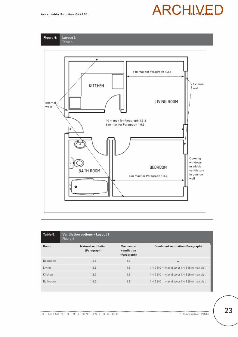
Table 5: Ventilation options – Layout 3Figure 4
Room Natural ventilation (Paragraph)
Mechanical ventilation (Paragraph)
Combined ventilation (Paragraph)
Bedrooms 1.3.5 1.5 –
living 1.3.5 1.5 1.4.2 (10 m max dist) or 1.4.3 (6 m max dist)
Kitchen 1.3.3 1.5 1.4.2 (10 m max dist) or 1.4.3 (6 m max dist)
Bathroom 1.3.3 1.5 1.4.2 (10 m max dist) or 1.4.3 (6 m max dist)
Figure 4: Layout 3 Table 5
External wall
Internal walls
10 m max for Paragraph 1.�.2� m max for Paragraph 1.�.�
� m max for Paragraph 1.�.�
� m max for Paragraph 1.�.�
Opening windows or trickle ventilators in outside wall
ARCHIVED

1 N o v e m b e r 2 0 0 82�
ARCHIVED
D E P A R T m E N T O F B U I l D I N G A N D H O U S I N G 1 N o v e m b e r 2 0 0 8
V E N T I L A T I O NI n d e x G4/VM1 & AS1
2�
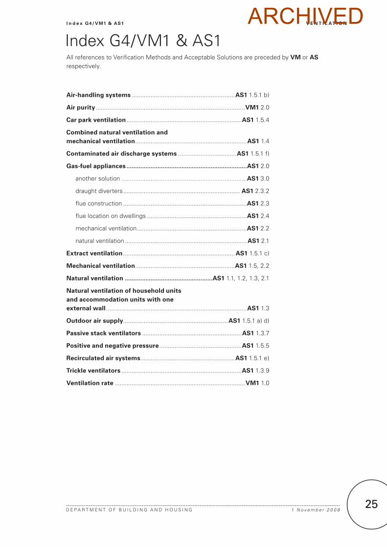
Index G4/Vm1 & AS1All references to Verification methods and Acceptable Solutions are preceded by VM or AS respectively.
Air-handling systems ............................................................AS1 1.5.1 b)
Air purity .......................................................................................VM1 2.0
Car park ventilation ...................................................................AS1 1.5.4
Combined natural ventilation and mechanical ventilation .................................................................AS1 1.4
Contaminated air discharge systems ..................................AS1 1.5.1 f)
Gas-fuel appliances ......................................................................AS1 2.0
another solution .........................................................................AS1 3.0
draught diverters .................................................................... AS1 2.3.2
flue construction ........................................................................AS1 2.3
flue location on dwellings ..........................................................AS1 2.4
mechanical ventilation ................................................................AS1 2.2
natural ventilation .......................................................................AS1 2.1
Extract ventilation .................................................................AS1 1.5.1 c)
Mechanical ventilation ..........................................................AS1 1.5, 2.2
Natural ventilation ...................................................AS1 1.1, 1.2, 1.3, 2.1
Natural ventilation of household units and accommodation units with one external wall ..................................................................................AS1 1.3
Outdoor air supply .............................................................AS1 1.5.1 a) d)
Passive stack ventilators ..........................................................AS1 1.3.7
Positive and negative pressure ................................................AS1 1.5.5
Recirculated air systems .......................................................AS1 1.5.1 e)
Trickle ventilators ......................................................................AS1 1.3.9
Ventilation rate ............................................................................VM1 1.0
ARCHIVED

1 N o v e m b e r 2 0 0 82�
ARCHIVED