compliments of: the fieldbus foundation
TRANSCRIPT

Compliments of: The Fieldbus Foundation
© 2004-2012 Fieldbus Foundation

Revision 3.2.1 - ii - September 2012
FOUNDATION™ Fieldbus System Engineering Guidelines
(AG-181) Revision 3.2.1 This preface, as well as all footnotes and annexes, is included for informational purposes and is not part of AG-181. This document has been prepared under the direction of the End User Advisory Council (EUAC) of the Fieldbus Foundation. To be of real value, it should not be static but subject to periodic review. Toward this end, the foundation welcomes all comments and criticisms, and asks that they be addressed to:
Fieldbus Foundation
9005 Mountain Ridge Drive Bowie Building - Suite 200
Austin, Texas 78759-5316 USA Tel: 512.794.8890 Fax 512.794.8893
E-mail: [email protected] Visit our Worldwide Web Site:
www.fieldbus.org This document in its present revision, and at time of publication, recognizes that High Speed Ethernet (HSE) products are available from the Fieldbus Foundation and its members. Although HSE implementation is currently not widespread, guidelines for installation and use are provided. The protocol for FOUNDATION™ Fieldbus for Safety Instrumented Functions (FF- SIF) has been approved by TÜV and its implementation has been successfully demonstrated. Commercial products for installations are not yet available, but practical pilot installations are being commissioned and planned. Preliminary guidelines for design and implementation are included in this revision. A future revision of this document will incorporate further guidelines for the design, installation and implementation of FOUNDATION Fieldbus for Safety Instrumented Functions. The use of specific vendors/manufacturers in this document does not entail implicit endorsement of the product over other similar products by the authors or the Fieldbus Foundation. Individuals using this document are encouraged to seek out equivalent function equipment from other sources of which the authors may be unaware. To assist in our efforts to make this document as relevant as possible, should such equipment be known to a user of this document, please forward that information to the address given above.
It is the policy of Fieldbus Foundation to encourage and welcome the participation of all concerned individuals and interests in the development of FOUNDATION fieldbus standards, recommended practices, and technical reports. Participation in the Fieldbus Foundation standards-making process by an individual in no way constitutes endorsement by the employer of that individual, of the Fieldbus Foundation, or of any of the standards, recommended

Revision 3.2.1 - ii - September 2012
practices, and technical reports that the Fieldbus Foundation develops. The Fieldbus Foundation would like to thank the End User Advisory Council and the members of the End User Councils who have committed so much time and effort to the preparation of this guide. David Lancaster (Editor) Trine University EUC, USA Dave Brown Bechtel OG&C EUC, USA Chuck Carter Lee College EUC, USA Bindert Douma STC-Brielle EUC, EMEA Clark Cogswell Shell Global Solutions EUC, USA Glenn Dehler Shell Global Solutions EUC, USA Patrick Flanders Saudi Aramco EUC, Saudi Arabia Audun Gjerde Shell Global Solutions EUC, EMEA Rong Gul Shell Global Solutions EUC, EMEA William Hamilton Shell Global Solutions EUC, USA Yoshitsugu Morioka Waseda University EUC, Japan Larry O’Brien (Editor) Fieldbus Foundation Fieldbus Foundation, USA John Rezabek Ashland EUAC Chairman Herman Storey Herman Storey
Consulting, LLC EUAC, USA
The Fieldbus Foundation wishes to acknowledge the following individuals for their dedication in the creation of the original version of this document. Without their dedication, this guide would not have been possible: Ian Verhappen (Editor) SAIT Chairman, EUAC, Canada Chris Baltus DSM EUAC, Europe John Bazley Beca Simons EUC, Australia Ambrose Hargan CSBP EUC, Australia Henry Marks Marks & Associates EUC, USA Norihko EGI IT Engineering (Retired) EUC, Japan Nola Ogar BP Group EUC, USA Deon Rae Chevron Texaco EUC, USA Jim Russell Keyfleet Pty. Ltd. EUAC, Australia Herman Storey Shell Global Solutions EUAC, USA Ron Szanyi ExxonMobil Director, Fieldbus Foundation Al Chan Canadian Natural
Resources Ltd. EUC, Canada
Jim Sprague Ralph A. Hartman II
Saudi Aramco EUC, Saudi Arabia
Revision 3.2.1 - 3 - September 2012
Rev. No. Date Description By 0 October 2003 Original Release IV
1.0 December 2003 Editorial Revisions IV 2.0 August 2004 Editorial Revisions IV 3.0 January 2009 Incorporate Current Methodologies DSL 3.1 March 2010 Incorporate Editorial Comments and Revisions DSL 3.2 January 2012 Incorporate Editorial Comments and Revisions LOB 3.2 May 2012 Rework Sections on FISCO LOB 3.2 May 2012 Revised Sections on Design Rules LOB 3.2 May 2012 Revised Sections on Cable Length LOB 3.2 May 2012 Revised Sections on Surge Protection LOB 3.2 May 2012 Reformatted Document LOB 3.2 May 2012 Removed Appendix on Grounding and
Shielding LOB
3.2 May 2012 Revised Topology Drawings LOB 3.2 May 2012 Added Discussion on Existing Wiring LOB 3.2 May 2012 Revised Section on Segment Scheduling LOB
3.2.1 September 2012 Replaced Figure 7-6 LOB 3.2.1 September 2012 Replaced Figure 7-7 LOB 3.2.1 September 2012 Replaced Figure 7-8 LOB 3.2.1 September 2012 Replaced Figure 7-9 LOB 3.2.1 September 2012 Deleted Reference to IEC 60079-13 Standard LOB 3.2.1 September 2012 Revised Figure 7-2 LOB 3.2.1 September 2012 Revised Figure 7-3 LOB 3.2.1 September 2012 Revised Figure 7-4 LOB

Revision 3.2.1 - 4 - September 2012
Revision Memo REVISION 1.0 – DECEMBER 2003
Addition of Saudi Aramco contributors to preface Renumber 1.3.3 to 1.3.2 Renumber 4.4.3 to 4.4.2 Reference in Section 8.6.2 changed from 6.5.2 to 6.7.2
REVISION 2.0 – AUGUST 2004
Add abbreviation MOV – Motor Operated Valve to abbreviations list. Section 2.2.9 Addition of reference to AG-163 Section 2.3.5 Correct IAONA URL from http://www.iaona-eu-com to www.iaona.org Section 5.2.7 Statement of power conditioner isolation Section 6.3.5 Change to 8/20uS, not 8/20S Section 6.5 & 6.6 Rewritten Section 6.7 Addition of Section on FNICO. Renumber balance of Section 6 Section 7.3.3 Correction SM Timer default settings were 2440000 (76.25 seconds) changed to 1440000
(45 seconds) Table title changes “Network/Segment Checkout Form” and “Fieldbus Cable Checkout Form” Update noise levels to <75 mV and lowest signal level to 150 mV in “Network/Segment Checkout Form” REVISION 3.0 – JANUARY 2010 General revision Combined Sections 1, 2 and 3 Combined items from other documents Restructure sections to emulate a project development Added Project Requirements Section Added FOUNDATION Fieldbus for Safety Instrumented Functions Revised Host System Requirements Revised Software Configuration Guidelines Revised Field Device Requirements Revised Ancillary Device Requirements Revised Fieldbus Network/Segment Design Guidelines Revised Factory Acceptance Test Procedures Revised Site Installation Guidelines Revised Documentation Requirements Added Appendices REVISION 3.1 – March 2010 Incorporated comments Changed order of Sections 8 and 9 Added and revised order of Appendices
REVISION 3.2 – May 2012 Incorporate Editorial Comments and Revisions Rework Sections on FISCO

Revision 3.2.1 - 5 - September 2012
Revised Sections on Design Rules Revised Sections on Cable Length Revised Sections on Surge Protection Reformatted Document Removed Appendix on Grounding and Shielding Revised Topology Drawings Added Section on Use of Existing Wiring Clarified that VCRs are Typically not Used on Newer Systems Revised Section on Segment Scheduling Cleaned up References to ISA Standards Revised Grounding Graphics REVISION 3.2.1 – September 2012 Further Formatting Changes Replace Grounding Figures Remove Outdated Standards References Updated Figures on Segment Current Draw and Voltage

Revision 3.2.1 - 6 - September 2012
Caution The use of this guide may involve hazardous materials, operations or equipment. The guide cannot anticipate all possible applications or address all possible safety issues associated with use in hazardous conditions. The user of this guide must exercise sound professional judgment concerning its use and applicability under the user’s particular circumstances and according to their established corporate policies and procedures. The user must also consider the applicability of any governmental regulatory limitations and established safety and health practices before implementing this standard.
Disclaimer of Warranties This document is informative only and is provided on an “as is” basis only. The document may be subject to future additions, modifications or corrections without notice. The Fieldbus Foundation disclaims all warranties of any kind, express or implied, including any warranty of merchantability or fitness for a particular purpose, for this document. IN NO EVENT WILL THE FIELDBUS FOUNDATION BE RESPONSIBLE FOR ANY LOSS OR DAMAGE ARISING OUT OF OR RESULTING FROM ANY DEFECT, ERROR OR OMISSION IN THIS DOCUMENT OR FROM ANYONE’S USE OR RELIANCE ON THIS DOCUMENT.

Revision 3.2.1 - 7 - September 2012
How To Use This Document This document reflects standard industry practices for the application FOUNDATION fieldbus H1 and High Speed Ethernet (HSE) projects at time of publication. As this is a “living document,” it will be maintained and updated periodically to reflect changes in the technology including the further adoption and application of HSE and the further use of FOUNDATION Fieldbus for Safety Instrumented Functions. The authors recognize that each facility planning to or installing a FOUNDATION fieldbus project may not wish to adhere to all the recommendations as reflected in this guideline. Towards that end, the End User Advisory Council recommends that rather than change this document, which has several cross-references, users instead prepare a forward clearly identifying those sections to be modified or applied in a different way. An example of this follows: “XYZ Company applies Section 7.3.3 to provide additional grounding protection for field devices." Recommended changes, additions or suggestions should be forwarded via e-mail to: [email protected]
Revision 3.2.1 - 8 - September 2012
Table of Contents 1.0 INTRODUCTION .....................................................................................................................................................16
1.1 Contents ............................................................................................................................................................16
1.2 Purpose .............................................................................................................................................................17
1.3 Scope.................................................................................................................................................................17
1.3.1 General.......................................................................................................................................................18
1.3.2 Project Consideration.................................................................................................................................18
1.4 References.........................................................................................................................................................18
1.4.1 FOUNDATION Fieldbus Specifications............................................................................................................18
1.4.2 Industry Codes and Standards....................................................................................................................18
1.4.3 Other References .......................................................................................................................................19
1.5 Definitions .........................................................................................................................................................19
1.5.1 General Definitions ....................................................................................................................................19
1.5.2 FOUNDATION Fieldbus Definitions ................................................................................................................20
1.6 Abbreviations ....................................................................................................................................................33
2.0 FOUNDATION FIELDBUS PROJECT REQUIREMENTS..................................................................................................36
2.1 Introduction ......................................................................................................................................................36
2.2 Use of Approved Products ................................................................................................................................36
2.3 Early in the Project ............................................................................................................................................36
2.3.1 Project Evaluation ......................................................................................................................................36
2.3.2 Training ......................................................................................................................................................37
2.3.3 Implementation Basis.................................................................................................................................37
2.3.4 Host Selection ............................................................................................................................................37
2.3.5 Component Selection.................................................................................................................................38
2.3.6 Work Processes ..........................................................................................................................................38
2.3.7 Division of Responsibility ...........................................................................................................................39
2.3.8 Integration Tools between Offices .............................................................................................................39
2.3.9 Integration with Suppliers ..........................................................................................................................39
2.3.10 Device Integration Testing .......................................................................................................................39

Revision 3.2.1 - 9 - September 2012
2.4 During Project Design........................................................................................................................................39
2.4.1 Training (more, detailed)............................................................................................................................39
2.4.2 Risk Assessment Rules and Review ............................................................................................................40
2.4.3 Segment Loading Rules and Review...........................................................................................................40
2.4.4 Methods (Templates) .................................................................................................................................40
2.5 Implementation.................................................................................................................................................40
2.5.1 Training ......................................................................................................................................................40
2.5.2 Host System Performance..........................................................................................................................40
2.5.3 Diagnostics Training ...................................................................................................................................41
2.5.4 Maintenance Methods...............................................................................................................................41
2.5.5 Operations – How to Optimize the Use of FOUNDATION Fieldbus ...............................................................41
2.5.6 Review Installation .....................................................................................................................................41
2.5.7 Review Field Changes.................................................................................................................................41
2.6 Summary ...........................................................................................................................................................42
3.0 FOUNDATION FIELDBUS HOST SYSTEM REQUIREMENTS .........................................................................................43
3.1 Use of Standard Products..................................................................................................................................43
3.2 Spare Capacity and Expansion...........................................................................................................................43
3.3 Redundancy.......................................................................................................................................................44
3.4 Architecture of Engineering and Maintenance Workstations...........................................................................45
3.5 Interoperability .................................................................................................................................................46
3.5.1 Host Profile Registration Process ...............................................................................................................46
3.7 Additional Capabilities ......................................................................................................................................47
3.8 Support for FOUNDATION Fieldbus Functionality ................................................................................................47
3.8.1 Host System Fieldbus Functionality ...........................................................................................................47
3.8.2 Data Transfer Capabilities ..........................................................................................................................48
3.9 Configuration Tool.............................................................................................................................................48
3.9.1 Integration..................................................................................................................................................48
3.9.2 Features......................................................................................................................................................48
3.9.3 Capabilities .................................................................................................................................................49
3.9.4 Required Function Blocks...........................................................................................................................49
3.10 Troubleshooting, Maintenance and Diagnostics.............................................................................................50

Revision 3.2.1 - 10 - September 2012
3.11 Advanced Diagnostics and Computer-‐based Maintenance ............................................................................51
3.11.1 Asset Management Systems ....................................................................................................................51
3.11.2 Minimum Diagnostic Requirements.........................................................................................................51
4.0 SOFTWARE CONFIGURATION GUIDELINES ...........................................................................................................53
4.1 Control System Graphics ...................................................................................................................................53
4.2 FOUNDATION Fieldbus Device Segment Addressing ............................................................................................53
4.3 Control Functionality Location ..........................................................................................................................54
4.3.1 Recommendations for Display and Alarm of Loop Variables for Control in the Field:...............................55
4.4 Segment Scheduling ..........................................................................................................................................55
4.5 Configuration Options and Defaults..................................................................................................................56
4.5.1 Control Narrative........................................................................................................................................56
4.5.2 Configurable Options .................................................................................................................................56
5.0 FIELD DEVICE REQUIREMENTS ..............................................................................................................................57
5.1 Fieldbus Registration.........................................................................................................................................57
5.2 Support for FOUNDATION Fieldbus Functionality ................................................................................................57
5.3 Fieldbus Function Blocks ...................................................................................................................................57
5.4 User Application Blocks.....................................................................................................................................59
5.4.1 Resource Block ...........................................................................................................................................59
5.4.2 Transducer Blocks ......................................................................................................................................60
5.4.3 Function Blocks ..........................................................................................................................................60
5.5 Control and Data Handling ................................................................................................................................62
5.5.1 Fault Handling ............................................................................................................................................62
5.5.2 Regulatory Control .....................................................................................................................................63
5.5.3 Factory Configuration (Basic Ordering Information)..................................................................................64
5.6 Device Diagnostics.............................................................................................................................................64
5.7 Field Device Power ............................................................................................................................................65
5.7.1 Polarity .......................................................................................................................................................65
5.7.2 2-‐Wire.........................................................................................................................................................66
5.7.3 4-‐Wire.........................................................................................................................................................66
5.7.4 Short-‐circuit Protection..............................................................................................................................66
5.8 FOUNDATION Fieldbus Device Requirements for Safety Applications .................................................................66

Revision 3.2.1 - 11 - September 2012
6.0 SEGMENT COMPONENT REQUIREMENTS.............................................................................................................68
6.1 GENERAL ...........................................................................................................................................................68
6.2 POWER SUPPLIES ..............................................................................................................................................68
6.2.1 General.......................................................................................................................................................68
6.2.2 FOUNDATION Fieldbus Power Supplies .........................................................................................................68
6.2.3 Bulk Power Supplies ...................................................................................................................................68
6.2.4 FOUNDATION Fieldbus Power Conditioner ...................................................................................................69
6.3 FOUNDATION Fieldbus Terminators .....................................................................................................................70
6.4 Surge Protection................................................................................................................................................70
6.5 FOUNDATION Fieldbus Repeaters ........................................................................................................................70
6.6 FOUNDATION Fieldbus Field Device Coupler........................................................................................................71
6.7 FOUNDATION Fieldbus Cables ..............................................................................................................................71
6.7.1 General.......................................................................................................................................................71
6.7.2 Existing Wiring............................................................................................................................................72
6.7.3 Spur Cables.................................................................................................................................................72
6.8 On-‐line Diagnostic Tools....................................................................................................................................72
7.0 FIELDBUS NETWORK/SEGMENT DESIGN GUIDELINES ..........................................................................................74
7.1 FOUNDATION Fieldbus Network/Segment Topology ...........................................................................................74
7.1.1 Point-‐to-‐Point Topology .............................................................................................................................74
7.1.2 Tree Topology (Chicken Foot) ....................................................................................................................75
7.1.3 Spur Topology (Bus with Spurs) .................................................................................................................76
7.1.4 Combination Topology ...............................................................................................................................76
7.1.5 Daisy Chain Topology .................................................................................................................................77
7.2 FOUNDATION Fieldbus Wiring ..............................................................................................................................78
7.2.1 Cable Types ................................................................................................................................................78
7.2.2 Distance Constraints ..................................................................................................................................78
7.2.3 Home Run Cable (Trunk) ............................................................................................................................78
7.2.4 Spurs...........................................................................................................................................................79
7.3 FOUNDATION Fieldbus Power, Grounding & Lightning Protection ......................................................................79
7.3.1 Power .........................................................................................................................................................79
7.3.2 Polarity .......................................................................................................................................................80
Revision 3.2.1 - 12 - September 2012
7.3.3 Grounding ..................................................................................................................................................80
7.3.4 Fieldbus Cable Shielding.............................................................................................................................81
7.3.5 Segment Isolation Segregation and Surge Protection................................................................................86
7.3.5.1 Isolation...................................................................................................................................................87
7.3.5.2 Segregation .............................................................................................................................................87
7.3.5.3 Surge Protectors......................................................................................................................................87
7.3.6 Terminators................................................................................................................................................87
7.3.7 Repeaters ...................................................................................................................................................88
7.4 FOUNDATION Fieldbus Segment Risk Management.............................................................................................88
7.5 Segment Design Considerations........................................................................................................................89
7.5.1 Multivariable Devices .................................................................................................................................89
7.5.2 Discrete Devices .........................................................................................................................................89
7.5.3 Network/Segment Shorting .......................................................................................................................89
7.5.4 Transmitter Assignment .............................................................................................................................89
7.5.5 Multiple Process Variables .........................................................................................................................89
7.5.6 Device Diagnostic Alarms ...........................................................................................................................89
7.5.7 Device Segregation.....................................................................................................................................90
7.5.8 Combining Safety and Control on a Segment.............................................................................................90
7.6 Limited Power Installations...............................................................................................................................90
7.6.1 Fieldbus Intrinsically Safe Installations.......................................................................................................91
7.6.2 FISCO ..........................................................................................................................................................91
7.6.3 FISCO ic (Formerly Known as Fieldbus Non-‐Incendive Concept (FNICO) Installations ...............................93
7.6.4 High-‐power Trunk Installations ..................................................................................................................93
7.6.5 High-‐power Trunk with Current Limiting Device Couplers (Non-‐Incendive) ..............................................94
7.6.6 High-‐power Trunk with Isolating Device Couplers (Intrinsically Safe)........................................................94
7.7 FOUNDATION Fieldbus Loading and Calculations.................................................................................................94
7.7.1 Spare Capacity............................................................................................................................................94
7.7.2 Segment Execution Time............................................................................................................................95
7.7.3 Voltage Drop Calculations ..........................................................................................................................96
7.7.4 Fieldbus Attenuation Calculation .............................................................................................................101
7.8 FOUNDATION Fieldbus Network/Segment Naming Convention ........................................................................101
Revision 3.2.1 - 13 - September 2012
7.8.1 Segment Naming Convention...................................................................................................................101
7.8.2 Loop and Instrument Naming Convention ...............................................................................................102
7.8.3 Spur Naming Convention .........................................................................................................................102
8.0 SITE INSTALLATION GUIDELINES .........................................................................................................................103
8.1 Introduction ....................................................................................................................................................103
8.2 Network Installation........................................................................................................................................103
8.2.1 Initial Cable Checkout...............................................................................................................................103
8.2.2 Cable Installation......................................................................................................................................103
8.3 Fieldbus Segment Commissioning Form .........................................................................................................104
8.4 Test Equipment ...............................................................................................................................................104
8.5 Installation of FOUNDATION Fieldbus Instruments and Wiring..........................................................................104
8.5.1 Wiring.......................................................................................................................................................104
8.5.2 Instrument Ground System......................................................................................................................105
8.5.3 Segment Checkout and Commissioning ...................................................................................................105
9.0. ACCEPTANCE TESTING REQUIREMENTS.............................................................................................................107
9.1 Introduction ....................................................................................................................................................107
9.2 Assumptions....................................................................................................................................................107
9.3 Device Integration Testing Requirements:......................................................................................................108
9.4 Factory Acceptance Test (FAT) Requirements: ...............................................................................................109
9.5 Site Acceptance Testing Requirements...........................................................................................................110
9.6 Segment Testing/Commissioning Requirements ............................................................................................110
9.6.1 Segment Testing.......................................................................................................................................110
9.6.2 Segment Commissioning ..........................................................................................................................111
10.0. FOUNDATION FIELDBUS DOCUMENTATION REQUIREMENTS.............................................................................112
10.1 General..........................................................................................................................................................112
10.2 Drawings........................................................................................................................................................112
10.2.1 Segment Drawings .................................................................................................................................112
10.2.2 Soft Data.................................................................................................................................................112
10.2.3 Location Drawings ..................................................................................................................................113
10.3 Instrument Index/Database ..........................................................................................................................113
10.4 Graphics ........................................................................................................................................................113

Revision 3.2.1 - 14 - September 2012
10.5 Manufacturer Documentation ......................................................................................................................113
APPENDIX 1: HOST INTEROPERABILITY SUPPORT TEST.............................................................................................114
APPENDIX 2: CABLE CHARACTERISTICS .....................................................................................................................117
A2.1 General .........................................................................................................................................................117
A2.1.1 UL Listing................................................................................................................................................117
A2.1.2 Temperature Range ...............................................................................................................................117
A2.1.3 Optional Characteristics.........................................................................................................................117
A2.2 Characteristic Impedance, Z0........................................................................................................................117
A2.3 Attenuation...............................................................................................................................................117
A2.4 Wire ..........................................................................................................................................................117
A2.5 Shield Construction Requirements ...........................................................................................................118
A2.6 Wire-‐to-‐Shield Capacitance Unbalance ....................................................................................................118
A2.7 Wire Twists Per Meter ..............................................................................................................................118
A2.8 Minimum Bend Radius..............................................................................................................................118
A2.9 Jacket Resistance ......................................................................................................................................118
APPENDIX 3: RISK MANAGEMENT ............................................................................................................................119
A3.1 Process Effect Ranking HIGH Criteria ............................................................................................................119
A3.2 Process Effect Ranking MEDIUM Criteria......................................................................................................119
A3.3 Process Effect Ranking LOW Criteria.............................................................................................................119
APPENDIX 4: FIELDBUS SEGMENT TESTING ..............................................................................................................123
A4.1 Fieldbus Segment Commissioning Form ......................................................................................................123
A4.2 Sample Waveforms.......................................................................................................................................124
APPENDIX 5: FOUNDATION FIELDBUS SEGMENT AND LOOP DRAWINGS ....................................................................126
APPENDIX 6: MAINTENANCE GRAPHICS ...................................................................................................................131
APPENDIX 7: ACCEPTANCE TESTING PROCEDURES...................................................................................................133
A7.1 Introduction ..................................................................................................................................................133
A7.2 Device Integration Testing ............................................................................................................................133
A7.2.1 Functionality Test Procedure .................................................................................................................133
A7.2.2 Device Check ..........................................................................................................................................133
A7.3 Factory Acceptance Testing (FAT).................................................................................................................134
A7.3.1 H1 Interface or Linking Device Operation..............................................................................................134
Revision 3.2.1 - 15 - September 2012
A7.3.2 Redundancy Switch-‐over Test Procedure ..............................................................................................135
A7.3.3 Field Device Operation...........................................................................................................................135
A7.3.4 Data Reconciliation ................................................................................................................................135
A7.3.5 Verification of Control Strategies and Monitoring.................................................................................136
A7.3.5.1 Transfer of Data to HMI or Historian ..................................................................................................136
A7.4 Site Acceptance Testing Requirements.........................................................................................................136
A7.5 Segment Testing/Commissioning Procedure ................................................................................................136
A7.5.1 Segment Check ......................................................................................................................................136

Revision 3.2.1 - 16 - September 2012
1.0 INTRODUCTION
1.1 Contents
The FOUNDATION Fieldbus Engineering Guideline is separated into sections. The following is an explanation of the intent of each chapter: Section 01 – Introduction The purpose and scope of the FOUNDATION Fieldbus Engineering Guidelines, references used to compile FOUNDATION Fieldbus Engineering Guidelines and terms used specifically with FOUNDATION fieldbus technology. Section 02 – FOUNDATION Fieldbus Project Requirements Guidelines for implementing FOUNDATION fieldbus projects. Section 03 – FOUNDATION Fieldbus Host System Requirements Functional requirements of the Host system when used to implement FOUNDATION fieldbus technology. Section 04 – Software Configuration Guidelines Information, explanations and guidelines for use when configuring control system software for use in a strategy that incorporates FOUNDATION fieldbus. Items covered include control module configuration, function block implementation, condition-based monitoring software configuration, and alarm management and configuration. Section 05 – Field Device Requirements Functional requirements of the field devices when used to implement FOUNDATION fieldbus technology. Section 06 – Segment Component Requirements Functional requirements of the ancillary components such as bulk power supplies, power conditioners, Fieldbus power supplies, wire, etc., for use with FOUNDATION fieldbus technology implementation. Section 07 – Fieldbus Network/Segment Design Guidelines Information, explanations and guidelines for use when designing FOUNDATION fieldbus networks/segments, including wiring design. This document will supersede AG-140 Wiring and Installation Application Guide as well as AG-163 Intrinsically Safe Systems. Section 08 – Site Installation Guidelines Information and procedures for use when installing fieldbus networks/segments. This section also specifies the procedures required to check out a FOUNDATION fieldbus system, as well as identifying required tools for use in installing and maintaining FOUNDATION

Revision 3.2.1 - 17 - September 2012
equipment. Section 09 –Acceptance Test Requirements Tasks and functions required to perform Device Integration Testing, Factory Acceptance Testing, Site Acceptance Testing and Segment Testing/Commissioning of a control system utilizing FOUNDATION fieldbus technology. Section 10 – FOUNDATION Fieldbus Documentation Requirements Required documentation for use when designing and maintaining FOUNDATION fieldbus technology. Documentation such as control philosophy, P&IDs and instrument location drawings is covered in this chapter. Appendix 1 Host Interoperability Support Test Appendix 2 Cable Characteristics
Appendix 3 Shielding Methods
Appendix 4 Risk Management
Appendix 5 Fieldbus Segment Testing Documentation
Appendix 6 FOUNDATION Fieldbus Segment and Loop Drawings
Appendix 7 Maintenance Graphics
Appendix 8 Acceptance Testing Procedures
1.2 Purpose The FOUNDATION Fieldbus System Engineering Guideline is intended to compliment the principal’s instrument specifications. It details how fieldbus devices are specified, installed, configured, commissioned, which are different than conventional analog or "smart" instruments. This Engineering Guideline addresses the implementation of FOUNDATION fieldbus only. Other fieldbus technologies exist that may be integrated into the basic process control system, if the engineering design requires. FOUNDATION fieldbus is primarily used to replace the traditional analog input/output signal types, but is also used with discrete devices such as on/off valves and electric actuators. Moreover, FOUNDATION fieldbus transmitters often take the place of process switches. FOUNDATION fieldbus technology is chartered by the Fieldbus Foundation.
1.3 Scope This document will provide the definition of the design, specification, installation, configuration, commissioning for a FOUNDATION fieldbus-based control systems. A second Application Guide will be developed to define the Operation, Maintenance, and Asset Management of

Revision 3.2.1 - 18 - September 2012
FOUNDATION fieldbus-based control systems. This guideline will only discuss the voltage mode (parallel coupling) medium attachment unit, as defined in IEC 61158-2, operating at a signal speed of 31.25 k/bits per second (i.e., H1). FOUNDATION fieldbus systems include instruments and hosts that cover all applications and aspects of instrumentation and control. Therefore, it is intended that all FOUNDATION instrumentation and control system standards apply to FOUNDATION fieldbus systems, except as noted herein. This revision of the specification does not yet provide specific, recommended practices for the installation and use of FOUNDATION Fieldbus for Safety Instrumented Functions (FF-SIF), since actual installations are not yet fully implemented. Preliminary discussions of some of the requirements and potential practices are provided. Subject to the disclaimer at the front of this document, this Engineering Guideline applies to end-users, contractors and control system vendors.
1.3.1 General FOUNDATION fieldbus creates an Automation Infrastructure by using an all-digital, two-way multi-drop communications link among intelligent smart field devices and automation systems. FOUNDATION fieldbus is the Local Area Network (LAN) for instruments used in process automation with built-in capability to distribute the control application across the network.
1.3.2 Project Consideration As with any new project, it is critical that the right skill sets be brought forth for the project. The same is true for a fieldbus project. Experience has shown that training of all members of the project team, engineers, maintenance personnel, and operations staff is critical to the project success. This training should be provided at the “front end” of the project to minimize rework and through different stages of the project as project members come on board, in order to benefit from information gained through “experience.”
Bringing in the right consultants at key junctures in the project to review and advise on the next steps is also often a prudent investment.
1.4 References
1.4.1 FOUNDATION Fieldbus Specifications
1.4.1.1 FF-569 Host Interoperability Support Test Profile and Procedures 1.4.1.2 FF-831 Fieldbus Power Supply Test Specification 1.4.1.3 FF-844 H1 Cable Test Specification 1.4.1.4 FF-846 Device Coupler Test Specification 1.4.1.5 FF- 912 Field Diagnostic Profile
1.4.2 Industry Codes and Standards
1.4.2.1 IEC 61158-1: Introductory Guide

Revision 3.2.1 - 19 - September 2012
1.4.2.2 IEC 61158-2: Physical Layer Specification and Service Definition 1.4.2.3 IEC 61158-3: Data Link Layer (DLL) Service Definition 1.4.2.4 IEC 61158-4: Data Link Layer (DLL) Protocol Specification 1.4.2.5 IEC 61158-5: Application Layer Service Specification 1.4.2.6 IEC 61158-6: Application Layer Protocol Specification
1.4.2.9 CEI/IEC 61508: Functional Safety of Electrical/Programmable Electronic Safety-Related Systems
1.4.2.7 CEI/IEC 61511: Functional Safety – Safety Instrumented Systems for the Process Industry Sector
1.4.2.8 NAMUR NE91: Requirements for Online Plant Asset Management System 1.4.2.9 NAMUR NE107: Self-monitoring and Diagnosis of Field Devices
Note that the parts dealing with the DLL and the Application Layer contain parallel sections for eight different protocols, including FOUNDATION fieldbus. De-facto standards are available from the Fieldbus Foundation that will comply with and be compatible with the IEC 61158 suite of standards.
1.4.3 Other References
For further references, visit the Fieldbus Foundation website (www.fieldbus.org) and navigate to the “End User Resources” section.
1.5 Definitions
1.5.1 General Definitions The definitions below shall be included if the words defined are used in the Code of Practice.
The contractor is the party that carries out all or part of the design, engineering, procurement, construction, commissioning or management of a project, or operation or maintenance of a facility.
The manufacturer/supplier is the party that manufactures or supplies equipment and services to perform the duties specified by the contractor.
The principal is the party that initiates the project and ultimately pays for its design and construction. The principal will generally specify the technical requirements. The principal may also include an agent or consultant authorized to act for, and on behalf of, the principal. The principal may undertake all or part of the duties of the contractor.
The words shall/must/will indicate a mandatory requirement. The word should indicates an acceptable recommended course of action or feature based on past project implementations. The words may/can indicate one acceptable course of action.

Revision 3.2.1 - 20 - September 2012
1.5.2 FOUNDATION Fieldbus Definitions
The following represent definitions of terms commonly encountered in the use and application of FOUNDATION technology. A comprehensive list of definitions related to FOUNDATION fieldbus can be found on the Fieldbus Foundation web site at http://www.fieldbus.org.
A Acyclic Period Also known as background traffic or unscheduled communication, the acyclic period is that portion of the communication cycle time during which information other than Publish/Subscribe data is transmitted. Typical information transmitted during this time includes Alarms/Events, Maintenance/ Diagnostic information, Program Invocations, Permissives/Interlocks, Display information, Trend Information and Configuration. Application Layer A layer in the communication stack containing the object dictionary. Automation System A process automation, control, and diagnostic system composed of distinct modules. These modules may be physically and functionally distributed over the plant area. The automation system contains all the modules and associated software required to accomplish the regulatory control and monitoring of a process plant. This definition of automation system excludes field instruments, remote terminal units, auxiliary systems and management information systems. Auto Sense Capability by the system to automatically detect and recognize any hardware upon addition to or removal from the system without any user intervention. Auxiliary System A control and/or monitoring system that is stand-alone, performs a specialized task, and communicates with the automation system.
B Basic Device A Basic Device is any device not having the capability to control communications on an H1 fieldbus segment. Brick See Device Coupler
Bus A H1 FOUNDATION fieldbus cable between a Host and field devices connected to multiple segments, sometimes through the use of repeaters.

Revision 3.2.1 - 21 - September 2012
C Capabilities File A Capabilities File describes the communication objects in a fieldbus device. A configuration device can use Device Description (DD) Files and Capabilities Files to configure a fieldbus system without having the fieldbus devices online. Common File Format (CFF) File An ASCII text file used by the Host to know the device detailed fieldbus capabilities without requiring the actual device. This file format is used for Capabilities and Value Files. Communications Stack Layered software supporting communication between devices. A Communications Stack is device communications software, which provides encoding and decoding of User Layer messages, deterministic control of message transmission, and message transfer. Configurable The capability to select and connect standard hardware modules to create a system; or the capability to change functionality or sizing of software functions by changing parameters without having to modify or regenerate software. Configuration The physical installation of hardware modules to satisfy system requirements; or the selection of software options to satisfy system requirements. Connector A Connector is a coupling device used to connect the wire medium to a fieldbus device or to another segment of wire. Console A collection of one or more workstations and associated equipment such as printers and communications devices used by an individual to interact with the automation system and perform other functions. Control Loop A Control Loop is a group of Function Blocks (FBs) that execute at a specified rate within a FOUNDATION fieldbus device or distributed across the fieldbus network. Cycle The scanning of inputs, execution of algorithms and transmission of output values to devices. D
DART (Dynamic Arc Recognition and Termination) DART technology enables intrinsic safety of an electric circuit with dramatically increased
Revision 3.2.1 - 22 - September 2012
available power during normal operation. In the case of an unwanted, potentially threatening condition such as opening or closing of the electric circuit, DART technology puts the circuit into a safe state before critical levels are reached. A spark caused by opening or closing an electric circuit has a very characteristic and easily detectable change of current and voltage. This change is detected by DART technology and the circuit is switched off in only a few microseconds (µs). Thus, even at higher power levels sparks never become incendive. Pepperl+Fuchs in conjunction with PTB, the Physikalisch Technische Bundesanstalt in Germany and twelve other manufacturers is involved in introducing changes to international standard IEC 60079 . In order to facilitate easier practical application (e.g., interoperability between manufacturers) the working group targets introducing regulations for test and approval of dynamically acting power supplies and equipment into IEC 60079. Data Link Layer (DLL) The Data Link Layer (DLL) controls transmission of messages onto the fieldbus, and manages access to the fieldbus through the Link Active Scheduler (LAS). The DLL used by FOUNDATION fieldbus is defined in IEC 61158. It includes Publisher/Subscriber, Client/Server and Source/Sink services. Deterministic Ability to measure the maximum worst-case delay in delivery of a message between any two nodes in a network. Any network protocol that depends on random delays to resolve mastership is nondeterministic. Device Coupler A device coupler is a physical interface between a trunk and spur, and a device. Device Description (DD) A Device Description (DD) provides an extended description of each object in the Virtual Field Device (VFD), and includes information needed for a control system or Host to understand the meaning of data in the VFD. Discrete Control Control where inputs, algorithms, and outputs are based on logical (yes or no) values. In the case of FOUNDATION fieldbus, discrete includes any integer operation between 0-255. DI Discrete Input – the signal is from the field device to the Host system or another field device. DO Discrete Output – the signal is generated by the Host system or another field device and transmitted to a field device..
E EDDL

Revision 3.2.1 - 23 - September 2012
Electronic Device Description Language (see www.eddl.org) Ethernet Physical and data link layer defined by IEEE 802 standards used by FOUNDATION fieldbus HSE.
F Factory Acceptance Test (FAT) The final test at the vendor's facility of the integrated system being purchased. Fieldbus A Fieldbus is a digital, two-way, multi-drop communication link among intelligent measurement and control devices. It serves as a Local Area Network (LAN) for advanced process control remote input/output applications. Fieldbus Access Sublayer (FAS) The Fieldbus Access Sublayer (FAS) maps the Fieldbus Message Specification (FMS) onto the Data Link Layer (DLL). Fieldbus Messaging Specification (FMS) The Fieldbus Messaging Specification (FMS) contains definitions of Application Layer services in FOUNDATION fieldbus. The FMS specifies services and message formats for accessing Function Block (FB) parameters, as well as Object Dictionary (OD) descriptions for those parameters defined in the Virtual Field Device (VFD). Commentary: Network Management (NM) permits FOUNDATION fieldbus Network Manager (NMgr) entities to conduct management operations over the network using Network Management Agents (NMAs). Each NMA is responsible for managing the communications within a device. The NMgr and NMA communicate through use of the FMS and Virtual Communications Relationship (VCR).
FISCO Fieldbus Intrinsic Safe COncept. Allows more power to an IS segment for approved FISCO devices, enabling more devices per IS segment. The newest editions of the IEC standards specify that FISCO 'ia' is suitable for Zones 0, 1 and 2; FISCO 'ib' can be used in Zones 1 and 2; and FNICO can be applied in Zone 2. FNICO, the Fieldbus Non-Incendive COncept, allows more power to a fieldbus segment in a Zone 2 Area, thus enabling more devices per segment than is possible with a FISCO solution. It should be noted that FNICO is now known as FISCO ‘ic’. Commentary: FISCO eliminates the requirement of calculating entity parameters of capacitance and inductance when designing networks.
Flexible Function Block (FFB) A Flexible Function Block (FFB) is similar to a Standard FB, except that an application-specific

Revision 3.2.1 - 24 - September 2012
algorithm created by a programming tool determines the function of the block, the order and definition of the block parameters, and the time required to execute the block. FFBs are typically used for control of discrete processes and for hybrid (batch) processes. A Programmable Logic Controller (PLC) can be modeled as a Flexible Function Block device.
G Gateway Translates another protocol to FOUNDATION fieldbus or vice versa, for example HART to FOUNDATION fieldbus or Modbus to FOUNDATION fieldbus.
H H1 H1 is a term used to describe a FOUNDATION fieldbus network operating at 31.25 kbit/second. H1 Field Device An H1 Field Device is a fieldbus device connected directly to an H1 FOUNDATION fieldbus. Typical H1 Field Devices are valves and transmitters. H1 Repeater An H1 Repeater is an active, bus-powered or non-bus-powered device used to extend the range over which signals can be correctly transmitted and received for a given medium. A maximum of four Repeaters and/or active Couplers can be used between any two devices on an H1 FOUNDATION fieldbus network. Repeaters connect segments together to form larger networks. High Speed Ethernet (HSE) High Speed Ethernet (HSE) is the Fieldbus Foundation's high-speed control network running Ethernet and IP. FOUNDATION HSE can have the same Function Blocks as H1 and will be the technology of the wireless backhaul network. Host Control system that has FOUNDATION fieldbus capabilities to configure and operate FOUNDATION fieldbus segments. There are several classes of Host systems: Class
61 Integrated Host Primary, on process Host that manages the communication and application
configuration of all devices on a network. Class
62 Visitor Host Temporary, on process Host with limited access to device parameterization.
Class 63
Bench Host Primary, off process Host for configuration and setup of a non-commissioned Device
Class 64
Bench host Primary, off process Host with limited access to device parameterization of an off- line, commissioned device.
Class 71
Safety Integrated Host
(PRELIMINARY) Primary, on-process Host that manages the communication and application configuration of all safety and control & monitoring devices on a network.

Revision 3.2.1 - 25 - September 2012
Host Profile Registration The Fieldbus Foundation has been doing Host testing since its earliest days. Over the years, this process has evolved considerably. The Fieldbus Foundation's previous Host Interoperability Support Test (HIST) provided a host test protocol with no provision for formal product registration. With HIST, all the work was done by the Host vendor. It soon became clear, however, that testing and registration of Hosts was necessary. That’s when the foundation introduced our Host Profile Registration Process. Under the new Host Profile Registration Process, the foundation conducts functional testing with a test device and specialized test Device Descriptions (DDs) and Capabilities Files (CFs). Registered devices from different vendors are also used during testing. The Host profile under test must support a clear set of required features. A Host will conform to some, or perhaps all, features as defined by the Host feature checklist. However, because Hosts can have various definitions, not all features may be applicable to a Host implementation. Therefore, it is not expected that every Host should support each feature. Each feature contains a set of test procedures that are to be run against the Host or the fieldbus system using the Host. In order for a Host to claim conformance to the feature, the Host must be able to pass the test procedures defined by the feature. The features themselves are generic; therefore, manufactures will derive test cases, or actual implementation steps necessary to meet the requirements of the test procedure. Fieldbus Hosts successfully completing the test requirements are authorized to bear the official FOUNDATION product registration symbol. HSE Device An HSE Device is a FOUNDATION fieldbus device connected directly to High Speed Ethernet (HSE). Typical HSE Field Devices are HSE Linking Devices, HSE Devices running Function Blocks (FBs), and Host Computers. HSE Linking Device An HSE Linking Device is a device used to interconnect FOUNDATION fieldbus H1 fieldbus networks/segments to High Speed Ethernet (HSE) to create a larger system. HSE Switch An HSE Switch is standard Ethernet equipment used to interconnect multiple High Speed Ethernet (HSE) devices such as HSE Linking Devices and HSE Field Devices to form a larger HSE network. Input/Output (I/O) Subsystem Interface An Input/Output (I/O) Subsystem Interface is a device used to connect other types of communications protocols to a fieldbus segment or segments. Refer also to Gateway. Interchangeability Interchangeability is the capability to substitute a device from one manufacturer with that of

Revision 3.2.1 - 26 - September 2012
another manufacturer on a fieldbus network without loss of functionality or degree of integration. Instantiable The ability of Function Blocks (FBs) to create multiple tagged FBs of different types from a library as required by the application. Quantity per device is restricted by device memory and other resources. Interoperability Interoperability is the capability for a device from one manufacturer to interact with that of another manufacturer on a fieldbus network without loss of functionality. IS Intrinsic Safety ITK Interoperability Test Kit used by the Fieldbus Foundation to register devices and confirm compliance with the relevant FOUNDATION fieldbus standards. This is a pass/fail test. Only devices passing the full suite of tests receive the official FOUNDATION registration "tick mark."
J
K
L Link A Link is the logical medium by which FOUNDATION fieldbus H1 fieldbus devices are interconnected. It is composed of one or more physical segments interconnected by bus, Repeaters or Couplers. All of the devices on a link share a common schedule, which is administered by that link's current LAS. It is the Data Link Layer name for a network. Link Active Scheduler (LAS) A Link Active Scheduler (LAS) is a deterministic, centralized bus scheduler that maintains a list of transmission times for all data buffers in all devices that need to be cyclically transmitted. Only one Link Master (LM) device on a FOUNDATION fieldbus H1 Fieldbus Link can be functioning as that link's LAS. Link Master (LM) A Link Master (LM) is any device containing Link Active Scheduler (LAS) functionality that can control communications on a FOUNDATION fieldbus H1 Fieldbus Link. There must be at least one LM on an H1 Link; one of those LM devices will be elected to serve as LAS. Link Objects

Revision 3.2.1 - 27 - September 2012
A Link Object contains information to link Function Block (FB) Input/Output (I/O) parameters in the same device and between different devices. The Link Object links directly to a Virtual Communications Relationship (VCR).
M MAC Address A unique hardware address given to each Ethernet interface chip. Macrocycle The repetitious scheduling of the Function Block within all the devices on a segment. The LAS is responsible for scheduling of the segment macrocycle. Methods Methods appear in system software as step-by-step “wizards.” Methods are an optional (but highly desirable) addition to Device Descriptions (DDs). Methods are used to define/automate procedures (such as calibration) for operation of field devices. Mirror Function Block See Shadow Block Multi-bit Alert Support The capability to utilize the multi-bit alarm capability. Multi-bit alarms are generated when multiple alerts or alarms occur within the same field device. Mode Control block operational condition, such as manual, automatic, or cascade.
N Network A network as applied in this document is the termination of one or more fieldbus segments into an interface card of the Host system. Commentary: In this document, as has become industry practice, the term “segment” is used to represent a cable and devices installed between a pair of terminators. Network Management (NM) Network Management (NM) permits FOUNDATION fieldbus Network Manager (NMgr) entities to conduct management operations over the network by using Network Management Agents (NMAs). Each Network Management Agent (NMA) is responsible for managing the communications within a device. The NMgr and NMA communicate through use of the Fieldbus Messaging Specification (FMS) and Virtual Communications Relationship (VCR). Noise AV

Revision 3.2.1 - 28 - September 2012
Average noise in the network during the silence period between frames.
O Object Dictionary An Object Dictionary (OD) contains all Function Block (FB), Resource Block (RB) and Transducer Block (TB) parameters used in a device. Through these parameters, the blocks may be accessed over the fieldbus network. OPC (OPen Connectivity – formerly Object Linking and Embedding for Process Control) Software application allowing bi-directional data flow between two separate applications. These applications may be running on the same or on separate servers. Offline Perform tasks while the Host system is not communicating with the field devices. Online Perform tasks (configuration, etc.) while the Host system is communicating with the field devices. Operator Console A console used by an operator to perform the functions required to monitor and control his assigned units. P Physical Layer The Physical Layer receives messages from the Communications Stack and converts the messages into physical signals on the fieldbus transmission medium, and vice-versa. Q Quiescent Current The device power consumption or, the current drawn while the device is not transmitting. The current should be as low as possible to enable more devices and long wire lengths, particularly in intrinsic safety. R Redundant Configuration A system/subsystem configuration providing automatic switchover, in the event of a failure, without loss of a system function.
Revision 3.2.1 - 29 - September 2012
Regulatory Control The functions of process measurement, control algorithm execution, and final control device manipulation that provide closed loop control of a plant process. Resource Block (RB) A Resource Block (RB) describes characteristics of the fieldbus device such as the device name, manufacturer and serial number. There is only one Resource Block (RB) in a device. S
Schedules Schedules define when Function Blocks (FBs) execute and when data and status is published on the bus. Segment A Segment is a section of a FOUNDATION fieldbus H1 fieldbus terminated in its characteristic impedance. Segments can be linked by Repeaters to form a longer H1 fieldbus. Each segment can include up to 32 H1 devices. Commentary: In this document, as has become industry practice, the term “segment” is used to represent a cable and devices installed between a pair of terminators. The FOUNDATION fieldbus specifications use the term “network” to describe the system of devices. This document uses these terms “interchangeably.” See ANSI/ISA–50.02, Part 2 (IEC 61158-2): SEGMENT = The section of a fieldbus terminated in its characteristic impedance. Segments are linked by repeaters to form a complete fieldbus. Several communication elements may be connected to the trunk at one point using a multi-port coupler. An active coupler may be used to extend a spur to a length that requires termination to avoid reflections and distortions. Active repeaters may be used to extend the length of the trunk beyond that of a single segment as permitted by the network configuration rules. A fully loaded (maximum number of connected devices) 31.25 kbit/s voltage-mode fieldbus segment shall have a total cable length, including spurs, between any two devices, of up to 1,900 m. There shall not be a non-redundant segment between two redundant segments.
Self-Diagnostic Capability of an electronic device to monitor its own status and indicate faults that occur within the device. Splice A Splice is an H1 Spur measuring less than 1 m (3.28 ft.) in length. Shadow Block A shadow Function Block is set up in the centralized controller to mirror the data associated with an external Function Block located in an external device. The control routine of the centralized controller communicates with the external Function Block via the shadow Function
Revision 3.2.1 - 30 - September 2012
Block as if the external Function Block was being implemented by the centralized controller. The shadow Function Block automatically obtains current information associated with the external Function Block. In the case of a fieldbus protocol, this communication is accomplished using both synchronous and asynchronous communications. However, the shadow Function Block communicates with other Function Blocks within the centralized controller as if the external Function Block is being fully implemented by the centralized controller. Spur A Spur is an H1 branch line connecting to the Trunk that is a final circuit. A Spur can vary in length from 1 m (3.28 ft.) to 120 m (394 ft.). Standard Function Block (FB) Standard Function Blocks (FBs) are built into fieldbus devices as needed to achieve the desired control functionality. Automation functions provided by Standard FBs include Analog Input (AI), Analog Output (AO) and Proportional/Integral/Derivative (PID) control. The Fieldbus Foundation has released specifications for 21 types of Standard FBs. There can be many types of FBs in a device. The order and definition of Standard FB parameters are fixed and defined by the specifications. Stack A set of hardware registers or a reserved amount of memory used for calculations or to keep track of internal operations. Note: This is different than the Communications Stack defined above. Stack Test Testing of the Communications Stack to show that the device communicates when it should and stays silent when it should, as well as making sure that the device package messages properly. Rate/Stale Count This is a number corresponding to the allowable missed communications before a device will shed its control mode, as specified in the Function Block Application Process (FBAP). This is basically a Watchdog Timer. System Management (SM) System Management (SM) synchronizes execution of Function Blocks (FBs) and the communication of Function Block (FB) parameters on the fieldbus, and handles publication of the time of day to all devices, automatic assignment of device addresses, and searching for parameter names or "tags" on the fieldbus. T
Tag A tag identifies a physical device (PD_TAG) or a block (FB_TAG). Each tag is unique. Terminator
Revision 3.2.1 - 31 - September 2012
Impedance-matching module used at or near each end of a transmission line that has the same characteristic impedance of the line. Terminators are used to minimize signal distortion, which can cause data errors. H1 terminators also have another even more important function. They convert the current signal transmitted by one device to a voltage signal that can be received by all devices on the network. Topology Shape and design of the fieldbus network (e.g., tree branch, daisy chain, point-to- point, bus with spurs, etc.).
Transducer Block (TB) A Transducer Block (TB) decouples Function Blocks (FBs) from the local Input/Output (I/O) functions required to read sensors and command output hardware. Transducer Blocks (TBs) contain information such as calibration date and sensor type. There is usually one TB channel for each input or output of a Function Block (FB). Some devices may also include additional Transducer Blocks for configuring local displays and/or for specialized diagnostics. Transmitter A Transmitter is an active fieldbus device containing circuitry, which applies a digital signal on the bus. Trunk A Trunk is the main communication highway between devices on a FOUNDATION fieldbus H1 network. The Trunk acts as a source of main supply to Spurs on the network.
U User Application The User Application is based on "blocks," including Resource Blocks (RBs), Function Blocks (FBs) and Transducer Blocks (TBs), which represent different types of application functions. User Layer The User Layer provides scheduling of Function Blocks (FBs), as well as Device Descriptions (DDs), which allow the host system to communicate with devices without the need for custom programming.
V Views A mechanism used in Client/Server communications to pass a logical block of related information between two devices on the network as a means to reduce network traffic while still providing data in a timely fashion. Virtual Communication Relationship (VCR) Configured application layer channels that provide for the transfer of data between

Revision 3.2.1 - 32 - September 2012
applications. FOUNDATION fieldbus describes three types of VCRs: Publisher/Subscriber, Client/Server and Source/Sink. Knowledge of VCRs is generally not required for newer systems that are available today. Virtual Field Device (VFD) A Virtual Field Device (VFD) is used to remotely view local device data described in the object dictionary. A typical device will have at least two VFDs.
W Wizard A Wizard is a means of automating procedures in Microsoft Windows™. Wizards can be used to implement methods. Workstation A set of electronic equipment including, at a minimum, one monitor, keyboard(s) and associated pointing device(s).
X
Y
Z

Revision 3.2.1 - 33 - September 2012
1.6 Abbreviations
Abbreviations Description
AI Analog Input
AO Analog Output
BPCS Basic Process Control System
BPS Bulk Power Supply
CAPEX Capital Expenditure
CCR Central Control Room
C/S Client/Server
CiF Control in the Field
CFF Common File Format
DCS Distributed Control System/Digital Control System
DI Discrete Input
DD Device Description
DLL Data Link Layer
DO Discrete Output
DTM Device Type Manager
EDDL Electronic Device Description Language
ESD Emergency Shut Down
FAR Field Auxiliary Room
FAS Fieldbus Access Sublayer
FB Function Block
FDT Field Device Tool
FF FOUNDATION Fieldbus
FF-SIF FOUNDATION Fieldbus for Safety Instrumented Functions
FFB Flexible Function Block
FFPS FOUNDATION Fieldbus Power Supply
F&G Fire and Gas
HIST Host Interoperability Support Testing
HMI Human Machine Interface
HSE FOUNDATION High Speed Ethernet
IEC International Electrotechnical Commission
I/O Input Output

Revision 3.2.1 - 34 - September 2012
Abbreviations Description
IPF Instrument Protective Function
IS Intrinsic Safety
IT Information Technology
ITC Instrument Tray Cable
ITK Interoperability Test Kit
LAS Link Active Schedule
LM Link Master
MAI Multi Analog Input
MAO Multi Analog Output
ML Manual Loader
MOV Motor Operated Valve
MV Manipulated Variable (controller output)
NM Network Management
OD Object Dictionary
OPEX Operational Expenditure
PCS Process Control System
PAS Process Automation System
P/S Publish/Subscribe
PD Proportional/Derivative Control
P&ID Process & Instrumentation Diagram
PID Proportional/Integral/Derivative Control
PTB Physikalisch-Technische Bundesanstalt
PV Process Variable
PLC Programmable Logic Controller
RA Ratio
RB Resource Block
SIF Safety Instrumented Function
SIS Safety Instrumented System
SIL Safety Integrity Level
SM System Management
SP Set Point
SS Safety Systems
TB Transducer Block

Revision 3.2.1 - 35 - September 2012
Abbreviations Description
TCO Total Cost of Ownership
TPE Thermo Plastic Elastomer
VCR Virtual Communication Relationship
Revision 3.2.1 - 36 - September 2012
2.0 FOUNDATION FIELDBUS PROJECT REQUIREMENTS
2.1 Introduction Proper utilization of FOUNDATION fieldbus technology in projects requires the following changes compared to traditional technologies for connection of field devices:
• Field devices and segments become an integral part of the DCS. This requires an integrated configuration, data management, and system architecture approach to field network design.
• System integration aspects of FOUNDATION fieldbus require some design activities to be performed earlier and with greater detail in the project lifecycle.
• More advanced functions are achieved in FOUNDATION fieldbus designs compared to traditional technologies. These advanced functions offer considerable opportunities for operating cost-saving and improved commissioning and start-up.
• System, field device, and segment component testing processes are more advanced than for simple analog connections.
• Traditional lines of authority between crafts and legacy-derived practices should be reviewed to determine if they are a suitable “fit” for FOUNDATION fieldbus.
2.2 Use of Approved Products Project staff shall utilize systems, field devices, and segment components that have passed rigorous approval processes. These processes include:
• Release testing by the vendor • FOUNDATION fieldbus tests (HIST, ITK – where applicable) • Host system vendor integration tests • Device Integration Tests (specific system and device combinations)
2.3 Early in the Project
2.3.1 Project Evaluation Document the anticipated use of FOUNDATION fieldbus. State where it can be used and where it is not yet appropriate. This document can be in report form, risk analysis or other formats. Document such areas as:
What benefits are expected Are they realistic based on experience? Can they be realized by the project? Can they be realized during the project schedule? What obstacles may be expected? Can they be resolved? What is the TCO (Total Cost of Ownership) on the project? • Should the project use conventional technologies in conjunction with

Revision 3.2.1 - 37 - September 2012
FOUNDATION fieldbus? Brainstorm the following: • Installation savings (schedule and cost) • Engineering (tools, schedule and cost) • Diagnostic tools (will they be useful and used during the project lifecycle?) • Maintenance (how to use FOUNDATION fieldbus to its greatest advantage)
• Installation (things do go wrong during construction) • Maintenance • Operations • Enterprise
2.3.2 Training Plan for and provide training for all necessary personnel at this stage of the project.
• Plan for all phases (e.g., design, system implementation, installation, commissioning and operation)
• Implement appropriate early training (include O&M, Management, etc.)
Training is available from the Fieldbus Foundation, Fieldbus Foundation Certified Training Centers, other training centers and Host or Device suppliers. A combination of these training sources may be appropriate.
2.3.3 Implementation Basis A well-defined Implementation Basis for the use of FOUNDATION fieldbus on the project will serve to keep the project on track (especially if it is a long-term effort). All parties involved (owner, engineering, equipment suppliers, contractors, etc.) will have the same expectation and design basis to work from.
• Prepare sound, clear design basis • Follow that basis • Keep current with the technology
2.3.4 Host Selection Correct Host selection for the project is a key element to the success of the project. Many projects tend to base major emphasis on cost of the DCS system only. The use of FOUNDATION fieldbus now means that the Host (DCS) and field devices are one system. Evaluation should incorporate as much of this concept as possible. Base the technical selection on at least the following:
• FOUNDATION fieldbus project capability • FOUNDATION fieldbus architecture (controller input or HSE) • Host vendor’s project experience with FOUNDATION fieldbus (complexity and
size of projects, etc.) • Ease of use • Integration of Asset Management System • Simulation capability for design and FAT • System diagnostics available • Local support capability • Device integration capability

Revision 3.2.1 - 38 - September 2012
• Training capability
2.3.5 Component Selection As with the Host selection, all field devices may not have the same capabilities, which are defined as needed in the Project Implementation Basis. Base the technical selection on the following:
• Meets area class requirements? • How does it work individually? • How does it work with other devices? • How easy to configure? • Does it perform as published? • Proven track record? • Integration with Host system(s)? • Support for EDDL and/or FDT/DTMs?
The following points should be considered as differentiators for FOUNDATION fieldbus devices:
• Function block types • Function block execution time • Diagnostics capability • Current consumption • LAS capable • Firmware download capable
Buy a device that fits your application requirements. More features do not always equal better functionality or a better fit for your application.
2.3.6 Work Processes Define any new or revised work processes, which may be required because of the use of FOUNDATION fieldbus. This is one of the most often overlooked aspects of a fieldbus project. If you do not pay attention to proper work processes, the people that need the data from fieldbus devices may not be able to get it, or you could remain stuck in traditional maintenance processes that are essentially transformed by fieldbus. Fieldbus is essentially a data pipeline, and users must plan where that flood of data is going to go and how it will be transformed into useful information. In most cases today, this is a secondary consideration that is only addressed after the system is up and running. Having a team in place consisting of personnel from all areas of the plant that are affected will expedite this process. What kinds of information are your maintenance personnel looking for? What about data storage and validation concerns for companies that must undergo regulatory compliance in industries such as pharmaceuticals and food & beverage? The information flow from the device level to the associated applications that need it must be mapped out prior to startup to achieve maximum benefits. Intelligent field devices are really data servers, and much of the information in these data servers is not appropriate for the control system operator. If you are dealing with a supplier that has an effective fieldbus configuration tool integrated with a good Plant Asset Management (PAM) application, it should be a minimal effort to get the right information to the right people at the right time.

Revision 3.2.1 - 39 - September 2012
2.3.7 Division of Responsibility Define Divisions of Responsibility between Owner, Engineer, Host and device suppliers, construction, etc.
2.3.8 Integration Tools between Offices Confirm or develop integration tools, which will be used by the different parties involved in the project (this is not unique to the use of FOUNDATION fieldbus).
2.3.9 Integration with Suppliers Determine how much involvement suppliers will have in the design, purchase, installation and training of the FOUNDATION fieldbus portion of the project.
2.3.10 Device Integration Testing Project staff should not assume that any FOUNDATION fieldbus device, in combination with any Host system, will provide full functionality of all advertised features of the Device or System. Project staff should utilize test or development systems as early as possible during the project design phase to ensure device integration. Typical configurations of hardware and software shall be thoroughly tested before high volume replication. These tests should not be postponed until FAT. Some examples of integration test procedures are given in Appendix 8. The device integration testing can be done at any one or a combination of the following: • At the EPC’s facility • At the Host supplier • Project office or Centre Of Excellence • Third-party laboratory (Fieldbus Foundation certified)
Interoperability testing for Devices and Hosts provides a base level of testing, but it is impossible to test every permutation of every Device and Host with every other Device or Host. The interoperability test provides a basic level of testing. Additional features may require additional testing.
FAT shall utilize simulated I/O, including FOUNDATION fieldbus I/O, if the Host systems support adequate simulation. In that case, field devices are not required at FAT. Appendix 5 gives examples of field tests procedures for FOUNDATION fieldbus Devices and Segments. These procedures are generally covered in more depth in other documents. They shall be planned for execution during the design phase and may be tested during integration tests described in Appendix 8.
2.4 During Project Design
2.4.1 Training (more, detailed) Plan for and provide training for all necessary personnel at this stage of the project.
Engineering Construction Owner/End User

Revision 3.2.1 - 40 - September 2012
2.4.2 Risk Assessment Rules and Review Risk assessment for segment loading is an optional exercise, applicable to sensitive processes or those projects, which may require detailed design documentation. Present industry experience has shown that segment availability is of less concern than in the past. If needed, develop a Risk Assessment Procedure (guidelines are provided in Section 7 and Appendix 4). The basis for the Risk Assessment should include at least:
FOUNDATION fieldbus final control element Risk Assessment Philosophy FOUNDATION fieldbus Final Control Element Process Effect Ranking Matrix Single failure of final control element Normal failure mode of final control element Number of devices per segment Diversity and redundancy End-user expectations and the perceptions of risk (how will a segment really
react?) Balance between availability and reliability
2.4.3 Segment Loading Rules and Review Establish the segment loading rules in the Implementation Basis and periodically review their application across the project. See Section 7.0 for Segment Design Guidelines.
2.4.4 Methods (Templates) Do they work with the Devices and Host selected? How easy or difficult are they to configure (drag and drop vs. keyboard entry)? Are there any “quirks” or special considerations? Review all options and defaults for selected Devices What are the unknowns before commissioning and startup?
2.5 Implementation
2.5.1 Training Plan for and provide training for all necessary personnel at this stage of the project.
Construction Commissioning/Start-up Owner/End-user
2.5.2 Host System Performance Evaluate the Host systems to determine such things as:
Are execution times as published? Does the Host slow down or have any other adverse effects due to loading? If planned software revisions contain significant changes, is there a plan for
implementation? Are the DD files for any new device revisions required available? How useful are the system diagnostics? Any unanticipated problems?
Revision 3.2.1 - 41 - September 2012
2.5.3 Diagnostics Training Plan for and provide training for all necessary personnel at this stage of the project.
• What is displayed and what does it mean? • What needs to be done if…….? • How can we do…....?
2.5.4 Maintenance Methods Plan for and provide training for all necessary personnel at this stage of the project.
What are the tools and equipment required? How is a Device disconnected and reconnected correctly? What is the procedure for replacing a Device when the new Device has a
different revision level? What happens in a download? How to use remote diagnostics? What is a valve signature and what does it mean? How to plan for additional segments after plant startup.
2.5.5 Operations – How to Optimize the Use of FOUNDATION Fieldbus Plan for and provide training for all necessary personnel at this stage of the project.
What parameters are available? What do they mean? How can combinations of parameter values be used to indicate how the process
is behaving? How to best use advanced diagnostic tools now available? How can valve diagnostics be used to verify or enhance performance? Development and use of diagnostic reports Who are the identified personnel to implement?
2.5.6 Review Installation As the project progresses to the field, periodically audit the installations to determine if proper installation procedures are being followed.
Cable routing Correct termination methods Termination of shields Bending radius of cable Grounding Are all Devices supplied with the expected DD? Location of device couplers or isolated device couplers
2.5.7 Review Field Changes When changes are made after the initial design, ensure that the following criteria are met:
Was a Risk Assessment Review done (if required)? Were segment design guidelines followed? Were installation practices adhered to? What effect will downloading the new Device have on the existing segment? When is the appropriate time to implement the change (can operations be
affected)?
Revision 3.2.1 - 42 - September 2012
2.6 Summary FOUNDATION fieldbus projects require an extra effort to ensure “certainty of outcome.” Owners/end-users, contractors and suppliers must be willing to provide that effort. Traditional design methods and execution are not enough. Thinking “outside the box” is required to ensure success—but users must stick to the rules once set. Early identification and implementation of “extra effort” items will pay off in the long run. Careful consideration of the addition of “bells and whistles” will avoid situations where “now we have them, what are we going to do with them?” Attention to details and standard installations can avoid costs and late design changes (additional costs and possible schedule delays).

Revision 3.2.1 - 43 - September 2012
3.0 FOUNDATION FIELDBUS HOST SYSTEM REQUIREMENTS
The selection of the Host (DCS) is essential for a successful FOUNDATION fieldbus technology implementation. The various Hosts reflect different levels of FOUNDATION fieldbus development. The Host system should be able to support EDDL, as well as FDT/DTM technology. Commentary: Adequate security measures are required with these tools to ensure that the Host system and device database match. The user should apply these tools with caution.
3.1 Use of Standard Products The system shall be composed of manufacturer’s standard hardware, systems software, and firmware that can be configured to meet the stated requirements. The vendor's standard system operating software shall not be modified to meet any of the end-user's requirements. Specifications for inquiries and purchase orders for Host systems shall require a Fieldbus Foundation “checkmark” indicating the proposed Host, at a minimum, has passed the HIST registration test. Distinctive “optional” features, such as multi-bit alert support, should be highlighted in light of the end-user’s strategy for maximizing the value of the installed system. Application software shall be designed in a manner that requires no modification to the system operating software. Software design shall be such that future revisions or updates of the system operating software will not affect the successful operation of the system. The DCS FOUNDATION fieldbus H1 network topology and settings shall comply with the recommended FOUNDATION fieldbus practices to enable communication with all targeted fieldbus devices. While it can be done at the Host or in the field, Function Block instantiation is recommended to be accomplished in the device manufacturer’s facility, in order to avoid extra field work or potential errors.
3.2 Spare Capacity and Expansion The DCS shall be supplied with minimum 20% hardware spare capacity at mechanical completion for all elements of the system configuration, including application software, graphics, history, reports, and trends. In addition, the system shall have sufficient spare performance (e.g., communication idle time) to execute all required communication including diagnostic information. Communication networks within the Host should include 20% spare H1 interfaces (ports) at mechanical completion for future system expansion. Each FOUNDATION fieldbus H1 segment shall be capable of supporting at least 12 FOUNDATION fieldbus physical devices

Revision 3.2.1 - 44 - September 2012
With a spare capacity of 20%, this implies the actual segment loading shall be no more than 10 physical devices per segment with two spares at the start of the project. Power supplies for FOUNDATION fieldbus segments shall be sized to support all future requirements including the 20% spare. In addition, there shall be sufficient room in field junction boxes to support the 20% spare requirement. The redundant fieldbus power supplies shall be sized taking into account the following considerations:
• In case of failure of one power supply unit, the backup unit shall be able to take the full load.
• The power supply spare capacity shall account for the recommendations above, including all of the spares requirements under (7.3.1).
Commentary: The base system is defined as the quantity of hardware and software needed to meet the project requirements. The level of spare capacity is a sensitive issue. Recommendations on spares range from the minimum 20% given above to 50% capacity for backplanes and marshalling terminals as this is a relatively small investment upfront, but significant to add financially and from a logistics point of view for installation as expansion modules. Others recommend a minimum of 20-25% spare capacity for all elements of the system configuration, including I/O cards, application software, graphics, history, reports, and trends.
3.3 Redundancy If redundancy is used for availability reasons, the following redundant components should be used:
• Redundant power feeds shall be provided to the bulk power supplies. The redundant power feeds shall be independent (e.g., one power feed from Power Bus A and the second power feed from Power Bus B). At least one of these power feeds shall be from a UPS unless the DCS power system has battery backup.
• Redundant bulk power supplies shall feed the FOUNDATION fieldbus power supplies. Each bulk power supply shall able to supply full load (including spare capacity) and shall annunciate loss of AC power and low battery voltage via separate discrete contacts. Where the bulk power supplies are comprised of multiple power modules, it shall be possible to remove and insert a power module under power. Each module shall annunciate trouble or error conditions via separate discrete contacts. In all cases, the discrete contacts shall be capable of supporting contact sense or voltage sense wiring and shall be energized with closed contact output when indicating an error-free condition.
• Redundant system controller power supplies with each controller power supply fed from an independent power source.
• Redundant system controllers.
Revision 3.2.1 - 45 - September 2012
• Redundant FOUNDATION fieldbus H1 interfaces. It shall be possible to replace either H1 card under power with no impact on the H1 segments associated with the redundant cards. It shall be possible to upgrade H1 card software/firmware without impacting communications on the related H1 segments.
• Redundant FOUNDATION fieldbus power supplies. It shall be possible to replace either FOUNDATION fieldbus power supply with no impact on the H1 segment(s) associated with the power supplies.
For more details on power supply redundancy, see Section 6.2. For more details on field device redundancy, see Section 7.5.7. Commentary Redundancy is also useful for on-line repair and upgrade of devices. For applications where a failed segment (all instruments and valves on the segment go to their fail or shelf state and remain there for up to several minutes after segment power is restored) has very minor consequences (near zero lost production, near zero incremental safety concerns, etc.) it is acceptable to forego the installation of redundant power supplies and redundant H1 interfaces. The design may also consider non-redundant H1 cards if the consequences of a “loss of view” are well understood and have minimal impact on the process availability and safety.
3.4 Architecture of Engineering and Maintenance Workstations It shall be possible to install more than one engineering workstation in a system. Only one engineering workstation shall be necessary to perform all control and FOUNDATION fieldbus configuration, database generation, and editing. However, it shall also be possible to use multiple engineering workstations simultaneously for configuration, database generation and editing. The automation system shall use a single, global configuration database to be shared by all components of the system. User shall not be required to enter the same data or configuration more than once. The maintenance workstation for diagnostic data handling should reside next to or be integrated with the engineering workstation, as FOUNDATION fieldbus maintenance requires simultaneous access to both platforms. Commentary: An integrated asset management package is required to gain the full benefits of FOUNDATION fieldbus during commissioning and lifecycle activities. Additional software (“snap-ons,” etc.) may be required to utilize the data available in field devices. The location of these software packages may depend on the Host system used.

Revision 3.2.1 - 46 - September 2012
3.5 Interoperability
3.5.1 Host Profile Registration Process Under the new Host Profile Registration Process, the Fieldbus Foundation conducts functional testing with a test device and specialized test Device Descriptions (DDs) and Capabilities Files (CFs). Registered devices from different vendors are also used during testing. The Host profile under test must support a clear set of required features. A Host will conform to some, or perhaps all, features as defined by the Host feature checklist. However, because Hosts can have various definitions, not all features may be applicable to a Host implementation. Therefore, it is not expected that every Host should support each feature. Each feature contains a set of test procedures that are to be run against the Host or the fieldbus system using the Host. In order for a Host to claim conformance to the feature, it must be able to pass the test procedures defined by the feature. The features themselves are generic; therefore, manufactures will derive test cases, or actual implementation steps necessary to meet the requirements of the test procedure. Fieldbus Hosts successfully completing the test requirements are authorized to bear the official FOUNDATION product registration symbol. Host Profiles and Classes A Host Profile defines a minimum set of FOUNDATION-specific features that must be implemented by a Host to achieve compliance to a specific Host class. A Host may incorporate one or more hardware and software components as defined by the Host manufacturer. Currently, the Fieldbus Foundation defines four profile classes. These include:
• Class 61 – Integrated Host: Primary, on-process Host that manages the communication and application configuration of all devices on a network.
• Class 62 – Visitor Host: Temporary, on-process Host with limited access to device parameterization.
• Class 63 – Bench Host: Primary, off-process Host for configuration and setup of a non-commissioned device.
• Class 64 – Bench Host: Primary, off-process Host with limited access to device parameterization of an off-line, commissioned device.
• Class 71 - SIF Integrated Host: Primary on-process Host for Safety Instrumented Functions.
Each of these host classes has its own set of characteristics, primary end users, and use cases. For the Integrated Host, primary characteristics are what you would normally associate with a DCS Host. Mandatory versus Optional and Prohibited Features Host testing and registration includes various levels of features for different Hosts. Depending on the type of Host, these features can be mandatory, optional, or even prohibited. For each profile, individual features are marked according to a requirement.
• Mandatory features for a particular Host must be implemented in order to achieve compliance for the relevant profile.
• Optional features may or may not be implemented. If implemented, the optional

Revision 3.2.1 - 47 - September 2012
features will be tested and credited as part of compliance for the relevant profile. • Prohibited features are restricted in that profile in order to minimize the possibility of
incurring unintended operations (such as changing critical configuration parameters that have been set up by another Host). A candidate cannot achieve compliance to a HIST profile if any prohibited features is available in that profile.
Staged Implementation: from A to B and Beyond When you look at host profile testing information for different classes, you will probably notice an “a” or a “b” designation. For example, a Host could be registered to a “Profile 61a” or “Profile 61b”. These alphabetical designations indicate different versions of host testing and registration. The “a” profiles represent the first wave of Host Profile testing that occurred after the original Host Interoperability Support Test. The “b” specifications represent a step forward for Host testing. In this new specification, more features are mandatory. The following Host features have gone from "optional" to "mandatory" with the new host profile 61b:
• Block Instantiation – Allows full utilization of fieldbus devices supporting instantiable function blocks. Primarily intended for control in the field (CIF).
• Multiple Capability Levels – For devices where certain blocks/features are optional (licensed), the standard or higher capability level can be set in the tag placeholder during system configuration to prevent unsupported blocks from being used in the control strategy. This prevents surprises during commissioning. It also makes device replacement easier.
• Enhanced Function Blocks – Allows full utilization of enhanced blocks (standard blocks with additional parameters).
• Profiled Custom Function Blocks – Allows full utilization of non-standard blocks. • Configuration of Scheduled Control Function Blocks – Allows developers to build CIF
control strategies. • DD V5.1 Device-Level Access (enhanced Electronic Device Description Language with
cross-block) – Makes fieldbus devices easier to use by enabling a dashboard with all diagnostics on the same page, and all setup on one page, regardless of which block it is in.
Beginning in 2010, all Hosts tested had to be tested under the “b” profiles. Hosts tested under the “a” profiles will be able to remain in the catalog of tested and registered Hosts, but there will be no further testing under the “a” profiles. When selecting a registered Host, take note of the class it was registered to in order to ensure you are purchasing the implementation you are looking for.
3.7 Additional Capabilities New capabilities of FOUNDATION fieldbus Hosts will be added to the list in Appendix 1, as they become available.
3.8 Support for FOUNDATION Fieldbus Functionality
3.8.1 Host System Fieldbus Functionality The Host system functionality should be designed to integrate the features of FOUNDATION fieldbus as follows:
• Automatic node addressing
Revision 3.2.1 - 48 - September 2012
• Interoperability • Direct configuration of devices • Direct integration of FOUNDATION fieldbus device operating, maintenance and
diagnostic data. • Tuning parameters, modes, alarms and quality of data. • Field devices shall be configurable while the Host system is operating without
shutting down the network. • The Host system shall enable new field devices to be added to an existing
network/segment (i.e., Device Tag/Placeholder) and fully configured without commissioning and start-up delays.
• The Host system should enable field device firmware to be updated without shutting down or impacting the publish/subscribe cycle of that H1 segment.
• Only registered FOUNDATION fieldbus DD and CFF files that have been tested and approved by the Host and device supplier should be used.
• The Host shall have a library of standard DD and CFF files or dedicated vendor files pre-installed.
3.8.2 Data Transfer Capabilities
A master database in the Host will hold most of the FOUNDATION fieldbus device parameters. External configuration tools (visitor Hosts such as handheld communicators or laptops) that bypass this master database shall not be used for configuration. FOUNDATION fieldbus devices enable diagnostic information. Integrated asset management packages should be employed to handle this diagnostic information. Procedures are necessary to ensure that the master database is up to date after a configuration change.
3.9 Configuration Tool A FOUNDATION fieldbus Host should have a configuration tool capable of online and off-line configuration. The configuration tool should have multi-user and multi-instance capability.
3.9.1 Integration
All Host FOUNDATION fieldbus functions, including engineering, configuration, maintenance, and operational display functions, should be integrated into a single, seamless Host system. Engineering, configuration, maintenance and operational features should apply consistently and seamlessly to conventional analog or discrete I/O, smart HART and proprietary I/O, bus- based I/O, and FOUNDATION fieldbus systems. Separate software tools, displays, or procedures specific for FOUNDATION fieldbus and different from conventional are not desirable.
3.9.2 Features FOUNDATION fieldbus Host configuration should be consistent in method and “look and feel” with conventional configuration. Internal mirror or shadow function blocks used by control systems to map FOUNDATION fieldbus Function Blocks to internal proprietary Function Blocks should be completely transparent to the configuration engineer, maintenance technician, and operator. It is essential that the shadow

Revision 3.2.1 - 49 - September 2012
block maintains data integrity, freshness and quality. The FOUNDATION fieldbus Host configuration tool should seamlessly and transparently integrate with, and maintain the master configuration database. Saves, restores and partial downloads of the master control system database should be seamlessly and transparently accomplished for both FOUNDATION fieldbus and conventional control strategies by the same configuration tool.
3.9.3 Capabilities The Host should be capable of offline configuration, simulation and testing of all FOUNDATION fieldbus Function Blocks and parameters, support of DD Services and Common File Format (CFF) specifications, as well as:
• Soft simulating and testing any and all FOUNDATION fieldbus control strategies. • Importing non-native, bulk configuration data for developing configuration of larger
project databases. • Simple or complex online FOUNDATION fieldbus control strategy creation or
modification. • Transparently managing the macrocycle schedule in order to maintain
minimum unscheduled acyclic time. • Providing alerts and messages for FOUNDATION fieldbus configuration errors.
3.9.4 Required Function Blocks The Host system shall support configuration and/or implementation of the following FOUNDATION fieldbus function blocks in field devices: I/O Function Blocks:
Function Implementation • Analog Input Function Block (AI) Required • Analog Output Function Block (AO) Required • Discrete Input Function Block (DI) Required • Discrete Output Function Block (DO) Required • Multiple Analog Input Function Block (MAI) Required • Multiple Analog Output Block (MAO) Optional • Multiple Discrete Input Function Block (MDI) Optional • Multiple Discrete Output Function Block (MDO) Optional

Revision 3.2.1 - 50 - September 2012
Analog Control Function Blocks:
Function Implementation
• Proportional Integral Derivative Function Block (PID)
Required
• Input Selector Function Block (IS) Optional
• Control Selector Function Block (CS) Optional
• Arithmetic Function Block (AR) Optional
• Signal Characterizer Function Block (SC) Optional
• Integrator Function Block (IT) Optional
SIF Function Blocks (for Class 71 Host only):
Function Implementation • SIF Analog Input Function Block (SIF-AI) Required • SIF Discrete Output Function Block (SIF-DO) Required
Commentary: Logical blocks should be used with caution in field devices at this time, as they are not yet uniformly applied by all manufacturers.
3.10 Troubleshooting, Maintenance and Diagnostics The Host should be capable of commissioning, setup, and maintaining all FOUNDATION fieldbus devices. This function should be integrated into the Host and available from Host workstations. The following functions should be supported:
• Report of load on all segments. • Error counters for all segments. • A schedule (time chart) report for H1 networks/segments. • An online reconcile function to allow change management when replacing field
devices. • Ability to enable/disable, prioritize, report, alarm, and acknowledge all device
alarms. • Add a new FOUNDATION fieldbus device to a network/segment. Add a future
FOUNDATION fieldbus device to a network/segment through use of placeholder templates.
• Methods for managing FOUNDATION fieldbus device states from/between offline, spare, standby (where applicable), commissioned, and mismatch states and
Revision 3.2.1 - 51 - September 2012
manage all address changes transparently. • Manual address changes or use of third-party configuration tools shall not be
required. • Simple and complex commissioning functions, including transmitter range
changes, zeroing, and control valve positioner setup (methods). • Support for DD methods and menus (wizards) for all maintenance functions
to walk technicians through the necessary maintenance procedures. • Provide specific maintenance displays, organized in a logical manner, for all
FOUNDATION fieldbus devices using specified language descriptors and definitions with access to all parameters.
• Ability to mirror existing FOUNDATION fieldbus device configuration (all FBs and parameters) onto a new FOUNDATION fieldbus device to allow quick device replacements.
• Display of commissioning and maintenance screens shall be possible from the operator/engineering workstation.
• Easily determine mismatches between the configuration in the field device and the configuration database.
3.11 Advanced Diagnostics and Computer-based Maintenance
3.11.1 Asset Management Systems
An integrated instrument health-monitoring (asset management) package will be required to gain full benefits of FOUNDATION fieldbus during commissioning and lifecycle activities. The necessary hardware and software should be an integral part of a Class 61 Host. The design should also include sufficient numbers and types of equipment to support the simultaneous tasks of operations, engineering and maintenance. Supplemental (temporary) hardware may be necessary during commissioning activities. Security of the integrated Host system needs to be protected through methods such as role-based access, ensuring control of data integrity while allowing access from all required locations or systems. Successful inclusion and implementation of asset management also requires early development of work processes to utilize the diagnostic tools as event triggers through techniques such as diagnostic alarm prioritization. Commentary: One primary benefit of installing a FOUNDATION fieldbus network is to get more “real time” information about the process and the device itself. The intelligent device can make available to the operator, technician, inspector and engineer or plant manager hundreds of different parameters about the process or instrument from a single smart device.
3.11.2 Minimum Diagnostic Requirements At a minimum, diagnostic capabilities shall report critical failures of devices. Diagnostics shall be reported to the Host via FOUNDATION fieldbus alarms and alerts. Polling schemes for diagnostics are not acceptable. Diagnostics should be reflected in data quality supplied to the
Revision 3.2.1 - 52 - September 2012
human interface and all applications or data users, as well as through separate diagnostic alarms intended for maintenance. To make optimal use of device intelligence, it is highly recommended to specify devices that support role-based diagnostics as delineated in FF-912, based on the NAMUR NE107 standard. Certain optional Host features are needed to make full use of the alerts generated by these field devices, such as Process Alert Management Configuration and following the HIST test for a Class 61 Integrated Host.
Revision 3.2.1 - 53 - September 2012
4.0 SOFTWARE CONFIGURATION GUIDELINES
4.1 Control System Graphics All modifications to, or reconstruction of, control system graphics shall comply with existing end user standards for Host system graphics detailing line colors, icon details, trend pages, alarm tracking, and historical data. While operator interface graphics need not differ substantially from conventional projects, users may wish to consider additional information (for example, signal status, actual mode not equal target mode) that will be meaningful to the operator. For device diagnostics and alert annunciation, dedicated FOUNDATION fieldbus faceplates shall be applied. Like process alarm management, no device alarms shall be presented to the operator which are redundant and do not motivate some specific operator action. Commentary: FOUNDATION fieldbus provides an abundance of additional information to the DCS system user. A dedicated asset management system should be employed for the diagnostic data. Otherwise, the panel operator will have to acknowledge all device status alarms and inactivate them from the operating console. Where an asset management system is not installed, the FOUNDATION fieldbus faceplates shall be installed which partially enable such activity.
4.2 FOUNDATION Fieldbus Device Segment Addressing Each fieldbus device shall have a unique physical device tag and corresponding segment address. Commentary: A device tag is assigned to the device when it is commissioned and (for most device states) retains the tag in its memory when it is disconnected. The network address is the current address that the fieldbus is using for the device.
The Fieldbus Foundation uses node addresses in the range 0-255. Each vendor allocates the node numbers in a way that is somewhat unique. Host Suppliers all have reserved low numbers for overhead and DCS interfaces, and a group above that for live field devices, and some higher numbers for spares.
Addresses used by FOUNDATION fieldbus are in accordance with the following ranges:
o 1–15 are reserved. o 16–247 are available for permanent devices. Some DCSs may further
subdivide this range. This range is typically shortened for efficiency. o 248–251 are available for devices with no permanent address such as new
devices or decommissioned devices. o 252–255 are available for temporary devices, such as handhelds.
Third-party systems or configuration tools connected through a communications interface to an H1 network shall NOT be used to:
• Interrupt the operation of any device within the system. • Change device addresses (handheld devices shall not be used to set the device tag

Revision 3.2.1 - 54 - September 2012
and address due to database inconsistency issues). • Affect the link schedule.
Third-party tools shall only use acyclic (client/server) communications. Communication interfaces shall have user-administered security to control read/write access and to select allowed functionality. Commentary: Default settings in some configuration tools can disrupt link operation without any overt action by the operator of the tool. The field device management implementation shall be capable of completely configuring parameters associated with FOUNDATION fieldbus devices. A FOUNDATION fieldbus H1 interface in the DCS always has the primary LAS functionality. A redundant H1 interface (if installed) will take over the LAS function as Backup Link Active Scheduler (BLAS) in case of failure of the first interface. In addition, a field device may have BLAS functionality. User experience has been that the real demand for a device-based Backup LAS is rare, in particular where redundant H1 interfaces have been specified (see Section 3.3). Since the BLAS functionality can add significantly to download times, users are advised to implement BLAS judiciously, only where no redundant H1 card exists, and only where specific loops are judged to require “zero” interruption of PID execution. An example might be a level loop on a vessel with very low residence time, where the default “hold last position” behavior would result in an undesirable process state. The field device with backup LAS enabled shall have the lowest commissioned FOUNDATION fieldbus device address.
4.3 Control Functionality Location Within FOUNDATION fieldbus devices, control is contained in software entities called modules. The control blocks can be a mix of both FOUNDATION fieldbus and other blocks. The fieldbus control blocks can be assigned to run in a field device or in the DCS controller. Control in the Field (CIF) is preferred when possible. Unless otherwise specified in project documentation, CIF optimizes communication as less H1 communication is required and control loops show lower variability due to better synchronization. CIF shall be used for simple single loop and cascade PID control within the same H1 segment. The PID function block shall be located in the final control element for single loop. The system shall be configured to allow the operator to manipulate the valve manually and provide alarm of the condition when a transmitter is completely inoperative due to local failure (such as power loss, communication loss, or complete electronics failure). Commentary: Transmitter and control valve positioners typically have a PID function block available, which raises the issue of where the PID function should be located. Issues such as H1 segment

Revision 3.2.1 - 55 - September 2012
communications overhead, execution speed, advanced diagnostics, failure mode, and operator access are generally considered when choosing where the PID block resides. However, the general consensus is that the PID block should be located in the control valve positioner. As with conventional control systems, loop and device failure modes need to be determined and the proper course of fail action identified for each control loop. If all function blocks of a single PID control loop cannot reside on the same segment, the PID control algorithm shall be placed in the DCS controller. Cascade PID control can be implemented in the field if all function blocks for both inner and outer loops reside on the same segment. Complex control shall be fully implemented in the controller.
Commentary: This restriction may not apply for systems supporting bridge capability between FOUNDATION fieldbus H1 networks. Note that bridging may be possible with the use of HSE, but not all Host systems with HSE support bridging. Note that there is limited user experience at this writing and, therefore, the user should thoroughly test any implementation using bridging. Each FOUNDATION fieldbus control strategy or module will be named as shown on the P&ID. The primary loop function block used for operator interface (AI or PID) will share the module name. With some systems, using consistent tagging conventions between devices and their associated loop can facilitate improved access to device information.
4.3.1 Recommendations for Display and Alarm of Loop Variables for Control in the Field:
Users will note that the measured/controlled value of any FOUNDATION fieldbus PID loop can potentially be accessed from a number of devices. When the PID resides in the final element (valve positioner), the HMI can be configured to access all the loop variables from there. However, a fault in that device will mean the measured value and alarms will cease updating on the operator interface. In such cases, it is better if the host accesses the PV and alarms from the transmitter (measuring device) directly wherever possible. Commentary: Users should also recognize that addressing “PV,” whether from the PID block itself or directly from the AI (analog input FB), makes its update part of the “asynchronous” or non-deterministic portion of loop communications (macrocycle), so display and trending latency may be increased. The same is true when accessing “read back” (typically actual valve position as seen by the positioner) from the loop’s AO block. Some vendors map the “read back” to the AO block’s BKCAL_OUT parameter (“Use PV for BKCAL_OUT” checkbox) which then makes it update with the deterministic portion of the macrocycle.
4.4 Segment Scheduling The cyclic communication (publish/subscribe) shall only be used for control applications including process indication points. Updating of graphics, faceplates, etc. as well as configuration and diagnostic information for maintenance shall be implemented acyclically (client/server). A minimum of 30% of macro cycle time should be allowed for unscheduled acyclic communication. Acyclic communication is classified into two types namely, scheduled, such as updating graphics, faceplate and unscheduled, such as configuration download and operator action. Sum

Revision 3.2.1 - 56 - September 2012
of the cyclic communication and the scheduled acyclic communication should be counted as the scheduled time.
Commentary: This represents the minimum acyclic time on a network. It is recommended that for a new installation, a minimum of 50% unscheduled acyclic time be available to allow for system expansion, addition of new devices, or modification to the configuration in the future. Commentary: Some Hosts (DCSs), by default, apply cyclic communication to update graphics. The correct communication type shall be selected during the control design and implementation phase.
4.5 Configuration Options and Defaults
4.5.1 Control Narrative A control philosophy guideline document shall be created for all FOUNDATION fieldbus projects. The guideline shall define all typical control strategies, with control modules, Function Blocks and all parameter configurations defined. This guideline shall set Function Block and control module philosophy for this and future FOUNDATION fieldbus projects at the facility. The configuration guideline shall be reviewed and approved by the end-user engineering representative.
4.5.2 Configurable Options Standard FOUNDATION fieldbus blocks have configurable options (e.g., Status_opts, Control_opts) for handling signal status, mode shedding, set point tracking, etc. As part of the guideline, or as separate standard “configuration templates,” the control narrative/guidance document should recommend default settings for relevant parameters and considerations for deviations from the recommended defaults. Some of the parameters to be addressed should include, but are not limited to:
Parameter Resource Block
Transducer Block
Function Block
Permitted Modes X X X Shedding Options X
Features - Reports X
PV Status X
Fault State X
Fault State Time X I/O Options X
Device Specific Parameters
X X X

Revision 3.2.1
September 2012
- 57 -
5.0 FIELD DEVICE REQUIREMENTS
5.1 Fieldbus Registration All devices must, as a minimum, satisfy the requirements of the Fieldbus Foundation’s registration laboratory. In the case of the foundation, this is the FOUNDATION fieldbus “check mark” registration logo and listing on the approved devices list maintained at www.fieldbus.org. The ITK (Interoperability Test Kit) is used in this registration process to check the basic FOUNDATION fieldbus functionality. This verifies interoperability of devices as indicated in the following example:
Example 5.1 FOUNDATION Fieldbus Registration “Check Mark” Logo.
Commentary: The end-user should verify with the Host vendor that their system is compatible with all versions of a device (current ITK version and all prior versions from 4.1 on).
5.2 Support for FOUNDATION Fieldbus Functionality All FOUNDATION fieldbus instruments should support Methods to allow automation of online procedures (such as calibration) from the Host. Most FOUNDATION devices have Methods to allow automation of online procedures (such as configuration) from the Host system.
Commentary: Methods are preferred for simple procedures. FDT/DTMs may be preferable for more complex procedures using graphical user interfaces and data retention storage, such as radar level and valve sequencing.
5.3 Fieldbus Function Blocks The following Function Blocks are defined by the Fieldbus Foundation. Not all of these Function Blocks are available for use in all field devices, and some are not available and/or do not yet have interoperability tests. Standard Function Blocks: As defined by FF-891: Function Blocks – Part 2. The ten standard Function Blocks are as follows:

Revision 3.2.1
September 2012
- 58 -
• AI - Analog Input • AO - Analog Output • B - Bias • CS - Control Selector • DI - Discrete Input
DO - Discrete Output ML - Manual Loader
• PD - Proportional/Derivative Control • PID - Proportional/Integral/Derivative Control • RA - Ratio
Advanced Function Blocks: Advanced Function Blocks defined in FF-892: Function Blocks – Part 3 are as follows:
• Device Control • Set Point Ramp • Splitter • Input Selector • Signal Characterizer • Dead Time • Calculate • Lead/Lag • Arithmetic • Integrator • Timer • Analog Alarm
Additional Function Blocks: Function Blocks are defined in FF-893: Function Blocks – Part 4 as follows:
• Multiple Analog Input • Multiple Analog Output • Multiple Discrete Input • Multiple Discrete Output
Flexible Function Blocks (FFBs) are defined in FF-894: Applications as follows:
• Flexible Function Block (IEC 1131 Logic) SIF Function Blocks are defined in FF-895: Safety Instrumented Functions (SIF) Function Blocks as follows:
• SIF Analog Input

Revision 3.2.1
September 2012
- 59 -
• SIF Digital Output
Commentary: It can be seen from this list that not all Function Block types are suitable or available for all instruments. It is, therefore, essential to make a considered choice when specifying the Function Blocks to be included in various field device types. Although it is appropriate to host most of these blocks in controllers, their use in field devices on H1 networks/segments may be limited (due to the availability of devices), to the following blocks: AI for transmitters, AO and PID for valves, and DI/DO for discrete devices. See Sections 4.3 and 4.5 for further guidance on use of field device Function Blocks. Additional Function Blocks are likely to be added in the future, therefore, it is wise to check Function Block availability with the instrument manufacturer and ensure that the Host system will allow the use of the desired Function Blocks at the time of purchase, thus ensuring that the features desired are available for use. It should be noted that there is seldom a need to have all Function Blocks available in all field devices. The user should also verify that functionality in the Host and field device is compatible, should it be necessary to revise the functionality location.
5.4 User Application Blocks Function Blocks handle the control strategy. The Function Block diagram is a graphical programming language for building control strategies. There are two kinds of blocks found in FOUNDATION fieldbus devices, device application blocks and configuration blocks.
Configuration blocks are used to configure devices. These are:
To configure the device: • Resource Block • Transducer Block holding the device diagnostic data
To configure the application: • Function Blocks whose schedule and usage is completely user-configurable
5.4.1 Resource Block
The Resource Block (RB) describes characteristics of the FOUNDATION device, such as the device name, manufacturer, and serial number. The following should be considered for design purposes:
• The user cannot make modifications • The user can change parameters • There is only one RB in a device. • The RB is the only obligatory block in FOUNDATION devices
• The RB contains ID and general information related to the whole resource or state of the resource (no real details about device functionality)
Revision 3.2.1
September 2012
- 60 -
• The RB contains overall health and operational status, includes write protection, and enables simulation, etc. Newer devices (ITK 6.x and above) may have device diagnostic alarm capability.
5.4.2 Transducer Blocks
The Transducer Block (TB) contains information such as calibration date and sensor type. Field Devices require at least one Transducer Block to make the device useful. TBs decouple FBs from the local Input/Output (I/O) functions required to read sensors and command output hardware (i.e., this is where parameterization, calibration and diagnostics for the device are carried out). Some devices have several TBs where dedicated TBs are used for diagnostics, multiple measurements, or to manage a device’s local display. Diagnostic coverage is all defined in the TBs of the device. Interoperability of all TB parameters with the Host system is essential for asset management.
The device vendor shall mark the diagnostic TB parameter as such in the DD (Device Description Files) for ease of access. Furthermore, a clear Help File shall be added to each parameter clarifying the device vendor’s knowledge on how to use the parameter information. The Fieldbus Foundation has defined several standard TBs including pressure, temperature, valves and some others. Devices that conform to these specifications are preferred.
5.4.3 Function Blocks
Function Blocks (FBs) should be employed in user-defined Function Block applications to provide various functions required in a control system (for example, input, output, signal selection, and other control actions). In other words, Function Blocks are the control strategy. FBs are built into FOUNDATION devices, as needed, to achieve the desired control functionality. Some FBs can be built into the devices and some can be instantiated (preferably at the factory). The factory instantiation option should be used as it results in less confusion and configuration effort. Reference should be made to the manufacturer's device manual for optimal configuration. Depending on the DCS (Host) manufacturer's policy, some of the specific device parameters may not be shown. In the case of diagnostics this may reduce the device functionality. Reference should be made to the manufacturer's device manual for optimal configuration. Not all available FB types may yet be included in the present ITK tick marking. However, not all FBs are required. Some FBs are only of interest if Control in the Field (CIF) is applied. Then, it is essential to make a considered choice when specifying the Function Blocks to be included in various field device types. Commentary: It is recommended to employ commonly used Function Blocks available in both the Host and

Revision 3.2.1
September 2012
- 61 -
field device. Use specialty Function Blocks with great care. Although appropriate to Host system controllers, these blocks may be limited to the following:
• AI for transmitters • AO and PID for valves • DI/DO for discrete devices
Additional Function Blocks are likely to be added in the future. It is, therefore, wise to check Function Block availability with the instrument manufacturer at the time of purchase, thus ensuring that the features desired are available for use. However, the interoperability of other than the essential FBs is not guaranteed with every Host system, thereby limiting the CIF applicability. The Fieldbus Foundation tests of Function Blocks only confirm that they are present and how their external interface behaves, not how well they work internally. Each manufacturer can configure the internal operations of Function Blocks as they wish and will, in fact, do so since this will give them a competitive advantage. It is thus worthwhile to check which manufacturer gives the best result in terms of macrocycle efficiency and the needs of the relevant process. This is mainly required when CIF is applied or fast loop execution is required. Example: Each manufacturer can implement the PID algorithm with unique equations while still providing control in a PID block. For some MOVs, it may also be advisable to check the FB execution times. The execution time of PID blocks differs per vendor. Furthermore, each manufacturer can implement the PID algorithm with unique equations while still providing control in a PID block. In most cases, the algorithm has no impact on the loop performance, as at present only simple control shall be applied with CIF. Section 5.3 provides a list of standard, advanced, and multiple I/O FBs. Commentary: The Fieldbus Foundation has defined dozens of standard Function Blocks. Additional Function Blocks may be defined and implemented by each manufacturer to accommodate individual control strategies and signal processing needs. Each manufacturer configures the internal operations of FBs as they wish—looking for competitive advantage. The Fieldbus Foundation tests only confirm that FBs are present and how their external interface behaves, not how well they work internally. It may be a good idea to, as far as possible, only use standard blocks in the control strategy. Because enhanced blocks (standard blocks with additional parameters) have extensions that are unique to each manufacturer, it becomes much more difficult to replace a device that uses enhanced blocks. Devices with "instantiable" blocks have the advantage that they typically support both the standard block (e.g., PID) plus enhanced blocks (e.g., enhanced PID with some additional features). This way, it becomes easy to choose standard blocks whenever sufficient, and enhanced blocks only when really required. Thus, instantiable blocks make interchangeability

Revision 3.2.1
September 2012
- 62 -
much easier.
5.5 Control and Data Handling
5.5.1 Fault Handling Fault detection and processing by ITK-approved FOUNDATION fieldbus devices complies with the FOUNDATION standards. PV status shall be available on tag basis and generated for inputs and calculated variables. In previous ITK versions, the PV status would be set to uncertain if the following condition was true:
• If a value is out of the scaled range Commentary: FOUNDATION fieldbus specifications no longer support flagging an out-of-range condition as uncertain. The PV status shall set to bad if any of the following conditions are true:
• If a value cannot be measured or calculated • If device diagnostics have identified a failure (e.g., open thermocouple)
PV status should be propagated through control schemes and to the historian, if applicable. It shall be possible for a PV status to be used as a logical input to initiate control algorithm changes. When a control algorithm's input is set to bad or uncertain, or in the event of communications subsystem failure, it shall be possible to configure the output to fail as follows:
• Configured fail state (hold last good value or shed to manual) • Mechanical fail state (loss of air position)
All final control elements shall have a configured fail-state on loss of segment communication.
Configured Fail State: The configured fail state shall be either open, closed, hold last position or a directed percentage open. The valve shall go to its configured fail state on loss of communication or upon a configured event. The configured fault-state value shall be 0% (closed) for fail closed and 100% (open) for fail open valves unless process conditions require a specific position.
A configured event may be:
• Loss of input signal to the valve PID block • Process event (emergency trip) or diagnostic event (valve fault)
Commentary: Some positioners offer fail-to-last position, however, this is device specific and shall be

Revision 3.2.1
September 2012
- 63 -
addressed on a case-by-case basis. Note that valve failure mode is a user’s choice and can be different for a diagnostic event or communications loss. An example might include Fail Last for communications loss, while a diagnostic event may put the valve in a predetermined failure position. Mechanical Fail-state: The Fault-state Time can be configured to a minimum of 5s (or any user-selected time). This will hold the last value (valve position) for that time period during a communication failure, and thereby increases plant availability by providing an opportunity to reestablish communications.
5.5.2 Regulatory Control Algorithms: Standard FOUNDATION fieldbus software algorithms shall be available to perform regulatory control functions. These process control functions shall be performed by using predefined algorithms with configurable parameters. Control algorithms are not standardized. For example, PID algorithms in field devices have different equations but all the parameter naming is the same. Also, PID algorithms in Host systems and in field devices may have different capabilities. The user should be aware of these differences and exercise care if switching between control in the Host vs. control in the field. Setpoint Clamps: Upper and lower clamps shall be available on all setpoints. Windup Protection: Control functions that include integral action shall be provided with windup protection. Windup protection shall inhibit the integral action when the control block output is constrained by conditions such as:
• Output at high or low limits of span. • Output at high or low clamps. • Output is connected to the setpoint of a secondary controller, which is clamped. • Output is not connected to any valid device or algorithm. • Output tracking is active unless the primary controller is connected to a secondary
controller which is not in cascade mode, or if a controller loses communication with the output module due to hardware failure.
The windup protection status shall be clearly visible to the operator in a standard faceplate display, so the operator is aware of this condition. The windup protection status shall set a parameter that is accessible to graphic displays and application programs. Control functions and computational functions shall include the ability to propagate the windup parameter through multilevel control strategies.

Revision 3.2.1
September 2012
- 64 -
5.5.3 Factory Configuration (Basic Ordering Information) FOUNDATION fieldbus instruments shall be configured by the manufacturer, including at least the following information:
• Device identification • Tag name
In addition, it may be advisable to order devices with the correct FOUNDATION fieldbus address (or at least a temporary address – see section 4.2) and with Link Master functionality (if available) turned off. Commentary: This will enable faster commissioning. If it is decided to not apply pre-tagged and pre- addressed devices, a dedicated commissioning work procedure is needed in which tag and address setting is performed.
5.6 Device Diagnostics The diagnostics shall be able to provide key information on the ability of the device to measure or control the process, including but not limited to basic device failure diagnostics and advanced diagnostics. Basic Diagnostics: Basic diagnostics are the device fault diagnostics that affect signal status, which shall be continuously viewable from any process control host. They help determine common problems with the device, communication path, and host. When transmitter diagnostics change the signal status to BAD or UNCERTAIN the default behavior is for the affected PID ACTUAL mode to shed to MANUAL. Users are encouraged to change this default behavior so that PID ACTUAL sheds mode only on BAD status. Select “treat UNCERTAIN as GOOD.” When an output (e.g., positioner) fault occurs, the affected loop PID is forced to IMAN (initialization manual). Advanced Diagnostics: Advanced diagnostics include full device diagnostics so that the device health can be determined without removing it from the process. Advanced diagnostics come in two forms, online and off-line. Online: Online diagnostics perform their function while the device is performing its normal function, and provide the capability to alert operations in real-time if a problem needs attention. This function provides one of the primary benefits of FOUNDATION fieldbus and should be supported by all devices as rapidly as possible. Offline: Offline tests provide limited benefits and may not justify their cost.

Revision 3.2.1
September 2012
- 65 -
FOUNDATION fieldbus devices should be capable of supporting incremental Device Description (DD) for extra functionality and/or software revisions in device memory. Capabilities include the following diagnostics and should provide key information on the impact that an output device has on the process, including but not limited to:
• Position accuracy • Operating resolution • Total valve travel • Packing friction and hysteresis • Static and sliding friction • Dead band • Operating temperature
For valve positioners, the dedicated software package to analyze the positioner data shall be fully interoperable with the Host system. Commentary: The selection of Host system asset management, positioner type (including diagnostic coverage) and interoperable software package is key for enabling successful diagnostics from FOUNDATION fieldbus positioner/valve combinations.
5.7 Field Device Power FOUNDATION fieldbus devices may be powered either from the segment (bus), or locally powered, depending on the device design. If at all possible, field devices should be bus powered. If a device requires more power than can be provided from a FOUNDATION fieldbus segment, the 4-wire approach is to be applied (separately powered). Commentary: Bus-powered devices typically require 10-30 mA of current at between 9 and 32 volts. Most devices have a current consumption at 15 to 17 mA. Devices should strive for minimum power consumption, without negatively impacting desired functionality.
5.7.1 Polarity
FOUNDATION fieldbus device communication signal shall be polarity insensitive. No inversion of the communication messages shall occur. Commentary: Some older FOUNDATION devices were polarity sensitive and, if installed incorrectly, could cause network problems. It is, therefore, considered good practice to maintain wire polarity and color throughout a project.

Revision 3.2.1
September 2012
- 66 -
5.7.2 2-Wire Field devices shall be loop-powered from the fieldbus power supply unless the device power consumption exceeds the limits of the segment. In the latter case, 4-wire configuration shall be applied.
5.7.3 4-Wire Externally powered devices (e.g., 4-wire devices) with FOUNDATION fieldbus shall have isolation between external power and fieldbus signal.
5.7.4 Short-circuit Protection Devices should be compatible with the selected type of short-circuit protection. The maximum spur current (generally the startup current of the field device) plus an allowance for at least one piece of test equipment on the spur should not exceed the current required to activate the short circuit protection. Commentary: Earlier versions of short circuit protection and devices, which drew relatively high current, could activate the short-circuit protection circuitry and thereby take the spur off line when test equipment such as a handheld communicator was connected to the spur. Later revisions of devices and test equipment draw less current and short circuit protection devices have increased the threshold to activate the protection. The user should evaluate the combination of devices, test equipment and wiring components to ensure compatibility.
5.8 FOUNDATION Fieldbus Device Requirements for Safety Applications
• The device shall be registered by the Fieldbus Foundation. • FOUNDATION for SIF transmitters used to sense the process may provide additional
diagnostics that will provide more detailed information for use to decide which action to take upon detection of the fault.
• It is preferable that the same physical hardware should be usable for safety and non- safety applications. It is also preferable that the firmware and software be selectable by application.
Commentary: When newly delivered, devices will reset to a default set of parameters upon initial power up. A device that supports both the normal and FOUNDATION for SIF protocols will startup such that it accepts both safety related and non-safety related configuration (i.e., it is ready to understand and speak both FOUNDATION fieldbus and FOUNDATION for SIF protocols.
• FOUNDATION fieldbus – Field devices shall be documented to be compliant to IEC 61508. • FOUNDATION for SIF field devices provide additional write access security measures to
device configuration blocks required to ensure compliance to IEC 61511 and IEC 61508. The devices shall include capability for remote locking and unlocking to prevent unauthorized access (change of FOUNDATION for SIF parameters). FOUNDATION for SIF
Revision 3.2.1
September 2012
- 67 -
field devices unlock message may be initiated by a physical key or password from an engineering workstation. When the write protection is applied, all FOUNDATION for SIF Function Blocks within the field devices return to the safe operating mode.
• FOUNDATION for SIF does not permit sub schedules. • FOUNDATION for SIF has no program invocation, action object, alerts, trends, block
instantiation or Flexible Function Blocks, and has restrictions on bridging. • When a device detects an internal failure, a failure status should be available to the
logic solver. • Once the safety-related configuration has been installed, the write-lock should be set. • FOUNDATION for SIF field devices clocks should be synchronized with the Host using
the regular FOUNDATION fieldbus clock synchronization mechanism and shall include the capability to time-stamp events (e.g., a pressure exceeds its limit).
Commentary: FOUNDATION for SIF field devices provide additional communications fault detection, which has been approved by TÜV to IEC-61508, including diagnostics to reduce the potential for undetected dangerous failures to a level acceptable for SIL 3 applications
Revision 3.2.1 - 68 - September 2012
6.0 SEGMENT COMPONENT REQUIREMENTS
6.1 GENERAL
A number of additional components are required to complete a FOUNDATION fieldbus segment. These segment components are discussed in detail in Sections 6.2 through 6.8, and should be reviewed by the Host system vendor as being compatible with their system.
6.2 POWER SUPPLIES
6.2.1 General
Power to segments shall be provided by FOUNDATION fieldbus power supplies that are fed by bulk power supplies. There are other options for the power supply architecture for FOUNDATION fieldbus, each having its benefits and limitations. However, options such as using non-isolated power conditioners are not recommended.
FOUNDATION fieldbus specifications allow segment supply voltage to range from 9 to 32 Vdc. Longer home runs benefit from higher power supply voltage. For most applications, trunk supply voltage at the power supply will be 24 ± 2 volts (typically, IS installations will be lower).
Any power supply can be used in combination with the fieldbus power supplies (See Section 6.2.2). The selection and implementation of power supplies is critical if only power conditioners are applied (not recommended, see Section 6.2.4).
6.2.2 FOUNDATION Fieldbus Power Supplies
FOUNDATION fieldbus power supplies are specialized power supplies that provide both the segment isolation from bulk power and the power conditioner in one unit. Power conditioning prevents the bulk power supply from shorting out the communications signal, preventing the segment from functioning. Isolation prevents ground loops and interference among segments.
FOUNDATION fieldbus power supplies are typically smaller than the bulk power supplies and are dedicated to a fixed number of segments. They shall have the appropriate approval: FF-831 “FOUNDATION Specification; Fieldbus Power Supply Test Specification” and associated check mark.
FOUNDATION fieldbus power supplies should be redundant, load sharing and output current limiting, and provide facilities for monitoring faults and failures. They shall be fed by dual DC bulk supply sources or by a redundant feed arrangement (not on a single fuse).
FOUNDATION fieldbus power supplies shall be used instead of power conditioners between bulk power supplies and segments.
6.2.3 Bulk Power Supplies
Bulk power supplies convert local electrical power to direct current. Multiple DC power supplies are often combined to meet the current demand of the load plus a safety factor. It is acceptable to use bulk supplies to power other loads in addition to FOUNDATION fieldbus power supplies.

Revision 3.2.1 - 69 - September 2012
A typical design includes redundant bulk power supplies with each having independent, redundant input supply circuits. A bulk power supply design may have its output voltage either floating or have the negative output connected to ground. Common practice is to ground the negative supply to control the discharge path should a voltage spike appear on the segment wiring back to the control system. Commentary: Grounding refers to the bulk power supply and not the FOUNDATION fieldbus power supply.
6.2.4 FOUNDATION Fieldbus Power Conditioner
The FOUNDATION fieldbus power conditioner provides impedance matching between the fieldbus signal and the bulk power supply. It may be active, using semiconductor components, or passive with only inductive and resistive components. It does not provide isolation and is therefore not recommended.
Figure 6.1: Typical Arrangement of 24 Vdc Bulk Power Supply Options to Fieldbus Power
Supply.

Revision 3.2.1 - 70 - September 2012
Commentary: A standard bulk power supply absorbs the communications signal as it attempts to maintain a constant voltage level. Short circuit protection is typically not provided by power conditioners. Lack of isolation and short circuit protection adds significant risk to field installations. Problems on one segment may affect other segments.
6.3 FOUNDATION Fieldbus Terminators FOUNDATION fieldbus segments require EXACTLY two terminators, one at each end of the trunk (home run) cable. The terminator is comprised of an RC network that provides 100 Ω impedance. The terminator allows the current-based FOUNDATION fieldbus communications signal to be viewed as a voltage while being offset on the DC segment voltage supply. Commentary:
1. Constructing your own terminator using a 100 Ω resistor and a 1 µF capacitor will not guarantee correct segment communications, and is therefore not recommended.
2. Most fieldbus power supplies and/or field device couplers have a built-in segment terminator.
3. Some wiring components have switchable terminators. Care should be taken to verify the correct quantity of terminators on a segment.
Terminators at a field device shall not be used (due to the impact on the whole segment should the device need replacement
6.4 Surge Protection
Surge protection for FOUNDATION fieldbus devices may be required in areas where induced voltage is an issue. This includes areas such as close wiring proximity where large inductive loads are started and stopped, or areas known for lightning incidence (associated with segments in tank farms, segments containing instruments on top of high towers or remote facilities such as pumping stations, well sites, etc.). Surge suppression consists of a low-capacitance device installed at the device's electrical connection. It shall normally appear as an open circuit to the spur and segment to prevent any adverse effect on communications. Commentary: Segment and spur protection is described in Section 7.3.5.3.
6.5 FOUNDATION Fieldbus Repeaters
Repeaters shall not be used without prior approval by the principal. Repeater functionality to extend the length of a fieldbus segment is not normally needed or recommended. Sometimes repeater functionality may exist in combination with IS Isolation for use in IS power supplies or IS isolated device couplers.
Revision 3.2.1 - 71 - September 2012
6.6 FOUNDATION Fieldbus Field Device Coupler
A FOUNDATION fieldbus device coupler or isolated device coupler (where applicable) is located where the trunk (home run) is connected to the various device spurs. It is typically the location of one of the terminators (associated with a segment), and the location of spur short-circuit protection. Only registered FOUNDATION fieldbus device couplers or isolated device couplers shall be applied. The couplers shall have built-in spur short-circuit protection (to minimize the impact of a short at one device affecting the whole segment). Spur short-circuit protection shall have visual indication (on a spur level) when short-circuit protection is active and the spur's maximum current shall be limited by area classification and the current available to the network.
The couplers should provide visual indication of segment power as a minimum.
6.7 FOUNDATION Fieldbus Cables
6.7.1 General FOUNDATION fieldbus cables shall be single-twisted or multi-twisted pair stranded tinned copper, individually shielded and overall shielded, 0.8 mm2 (#18 AWG) minimum with 300 V or better insulated, and shall have a UV-resistant, overall jacket (black provides the maximum UV protection). See Appendix 2 for cable requirements. The individual conductors within each pair will be color-coded; positive and negative being different colors. The pairs should be sequentially numbered. The trunk (home run) cable shall have one spare pair. Unused pairs of the trunk cable shall be connected together with the pair shield and grounded (for noise rejection) at the fieldbus segment shield ground connection (refer to Figures 7-6, 7-7, 7-8 and 7-9). See Appendix 2 for Cable Characteristics. The impedance of the cable shall be 100 Ω ± 20 Ω maximum. For longer (greater than 500 m) runs, 1.13 mm2 (#16 AWG) gauge wire should be used (to minimize the cable voltage drop) and 100 Ω ± 10 Ω specification. Although the larger cable cross-section may result in higher capacitance, the associated signal attenuation can be kept small and shall not be more than 3 dB/km at 39 kHz (this standard frequency is used to specify cable characteristics and is sufficiently close to the 31.25 kHz to be applicable). The trunk cable shall meet the ambient temperature range for the location in addition to the minimum installation temperature. In addition, installation of the cable shall comply with the manufacturer’s specified minimum bending radius. The individual pair shield shall be plastic-coated aluminum tape with a metallic surface inside in contact with a tinned copper drain wire. All individual pair shields shall be electrically isolated from each other and from the overall shield. The overall shield shall be plastic-coated aluminum tape, with the metallic surface in contact with a
Revision 3.2.1 - 72 - September 2012
tinned copper drain wire and wire braid (if used). A Factory Acceptance Test (FAT) shall be performed on all supplied FOUNDATION fieldbus cables. Pending a positive result of the factory test, an on-site insulation integrity test (between individual wires, individual pairs, and individual wires and shields) before installation may then be deemed optional. The conductor resistance, screen resistance, attenuation at 39 kHz and inductance of the cable shall comply with FOUNDATION fieldbus standards as stated in FF-844 and IEC 61158-2. Additional care shall be taken with intrinsically safe wiring techniques to ensure compliance with all local electrical approval requirements and site practices.
6.7.2 Existing Wiring Existing wiring can be used in FOUNDATION fieldbus installations, but should be tested to ensure it meets the qualifications outlined in section 6.7.1. Automated tools are available, such as the Relcom FBT-5, to test new or existing field wiring to determine its suitability for use in a FOUNDATION fieldbus network.
6.7.3 Spur Cables The spur cables shall meet the FOUNDATION fieldbus specification as discussed in Section 6.7.1. Commentary: An option may be to purchase single-pair FOUNDATION fieldbus cable and use this for both fieldbus spur wiring and for 4-20 mA device wiring.
6.8 On-line Diagnostic Tools
Several options exist for on-line diagnostic tools: permanently attached and portable devices. The following measurements shall be included in FOUNDATION fieldbus diagnostic tools:
• Voltage per segment • Segment noise • Maximum fieldbus signal (communications) level • Minimum fieldbus signal (communications) level • Low resistance between shield and negative signal pole • Low resistance between shield and positive signal pole
Optional measurements include:
• Fieldbus jitter on the segment If the on-line diagnostic tool is permanently installed as part of the FOUNDATION fieldbus power supply, additional information may be available, such as:
• Minimum, maximum and real-time bulk voltage supply to the FOUNDATION fieldbus power supply
• FOUNDATION fieldbus power supply operational status

Revision 3.2.1 - 73 - September 2012
• Minimum, maximum and real-time FOUNDATION fieldbus current Benefits of permanently installed diagnostic tools may include the ability to historize the data, and provide real-time alarming and trending of the data. Portable diagnostic tools assist in troubleshooting specific problems and may present additional data not available with permanent diagnostic tools. Permanently installed diagnostic tools shall only be considered if they are well integrated with the Host system.

Revision 3.2.1 - 74 - September 2012
7.0 FIELDBUS NETWORK/SEGMENT DESIGN GUIDELINES
7.1 FOUNDATION Fieldbus Network/Segment Topology The FOUNDATION fieldbus installation shall use the tree, spur or combination topology. Other topologies are not recommended. Commentary: Components of fieldbus segments can be connected together in various topologies. The topology selected is often, though not always driven by the physical device location in order to reduce installation costs. Hence, control narratives, plot plans and risk management considerations are used in addition to P&IDs and instrument indexes in the design of a fieldbus segment. Spur connections shall be connected to current-limiting connections to the bus via device couplers to provide short-circuit protection, and allow the ability to work on field devices without a hot work permit. The device coupler should provide a non-incendive or intrinsically safe connection to the field device. Exceptions to this may be considered when lightning surge protection is required (see Section 7.3.5.3). Commentary: The drops and current limiting can be provided by device couplers in junction boxes or by device couplers that can be field-mounted. The connection from the marshalling cabinet/Host to the coupler(s) in the field for the topologies shown in Sections 7.1.2, 7.1.3, and 7.1.4 are often provided by a multi-pair, individually shielded cable of the same type (ITC) used for the individual network and spur wires. However, spur wire may be of a smaller gauge (See Section 7.7.3). Commentary: Depending on whether or not segment bridging is supported in the Host, the desire to implement control in the field may drive the need to connect all the devices for the affected loop to reside on the same segment.
7.1.1 Point-to-Point Topology
This topology consists of a network having a maximum of only two devices. The network could be entirely in the field (e.g., a transmitter and valve, with no connection beyond the two) or it could be a field device connected to a Host system (doing control or monitoring). This topology is illustrated below and should not be used. It is not an economical design except as listed below.

Revision 3.2.1 - 75 - September 2012
Figure 7.1: Example of Point-to-Point Topology.
7.1.2 Tree Topology (Chicken Foot) This topology consists of a single fieldbus segment connected to a common junction box to form a network. This topology can be used at the end of a home run cable, and is practical if the devices on the same segment are well separated but in the general area of the junction box. When using this topology, the maximum spur lengths must be considered. Maximum spur lengths are discussed in Section 7.2.4. This topology is illustrated below in Figure 7.2.
Figure 7.2: Example of Tree (Chicken’s Foot) Topology.

Revision 3.2.1 - 76 - September 2012
This is the preferred topology to be used for reuse of existing wiring, as it is most similar to the conventional installation and will, therefore, provide the optimal use of existing infrastructure. Tree branch topology should be used for the following situations:
• Retrofit installations • High density of fieldbus devices in a particular area
This topology also allows maximum flexibility when configuring and assigning devices to networks/segments.
7.1.3 Spur Topology (Bus with Spurs)
This topology consists of fieldbus devices connected to a multi-drop bus segment through a length of cable called a spur. This technology is technically acceptable, but generally not a good economical choice when there is a high density of devices.
Figure 7.3: Example of Spur Topology. Bus with spur topology may be used in new installations that have a low density of devices in an area. Spurs shall be connected to current-limiting connections to the bus as this provides short-circuit protection.
7.1.4 Combination Topology Combinations of the above topologies must follow all the rules for maximum fieldbus network/segment length, and include the length of spurs in the total length calculation. These types of topologies are preferred for designs using bricks with tray cable. Spurs are permitted to extend only from trunk lines and not from other spur lines.
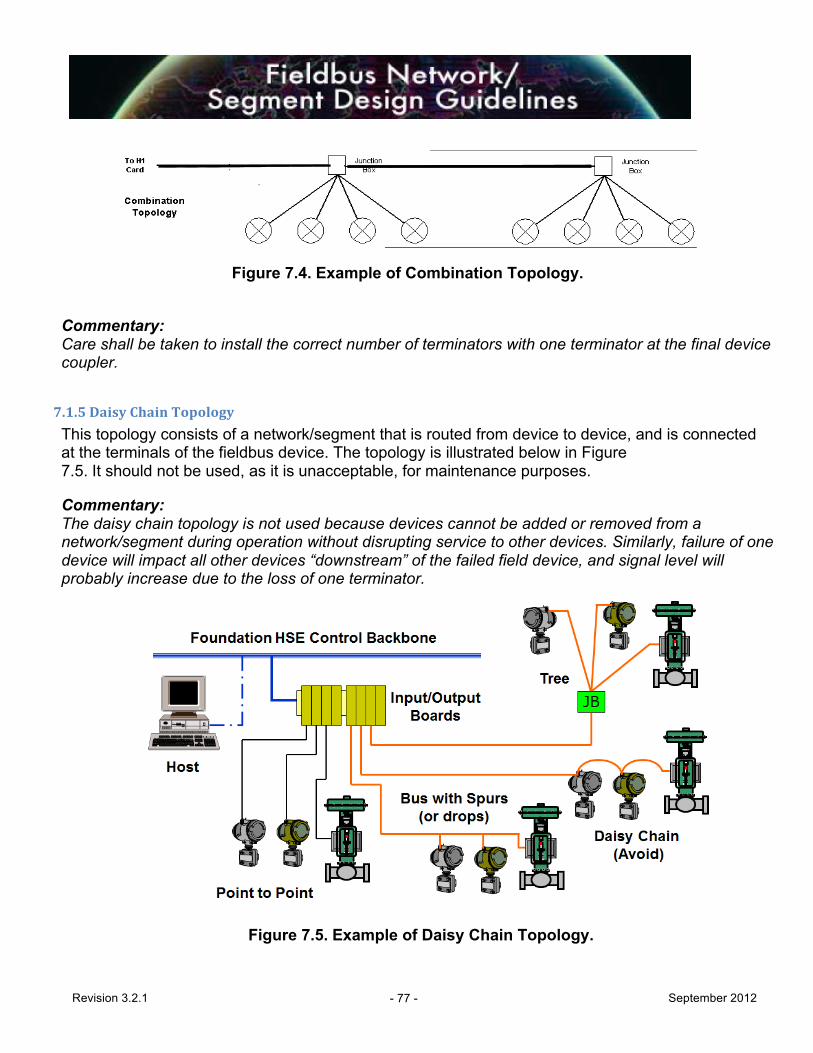
Revision 3.2.1 - 77 - September 2012
Figure 7.4. Example of Combination Topology.
Commentary: Care shall be taken to install the correct number of terminators with one terminator at the final device coupler.
7.1.5 Daisy Chain Topology
This topology consists of a network/segment that is routed from device to device, and is connected at the terminals of the fieldbus device. The topology is illustrated below in Figure 7.5. It should not be used, as it is unacceptable, for maintenance purposes. Commentary: The daisy chain topology is not used because devices cannot be added or removed from a network/segment during operation without disrupting service to other devices. Similarly, failure of one device will impact all other devices “downstream” of the failed field device, and signal level will probably increase due to the loss of one terminator.
Figure 7.5. Example of Daisy Chain Topology.

Revision 3.2.1 - 78 - September 2012
7.2 FOUNDATION Fieldbus Wiring
7.2.1 Cable Types
For information on FOUNDATION fieldbus wire and cable requirements, see Section 6.0 – Segment Design Components.
7.2.2 Distance Constraints The maximum allowed length of a non-intrinsically safe FOUNDATION fieldbus segment is 1900 m, provided that the cable meets the required specifications (See Section 6.7). This total segment length is computed by adding the length of the main trunk line and all the spurs that extend from it.
Total Segment Length = Trunk + All Spurs Commentary: From field experience, these lengths have been found to be conservative for high power trunks. As stated in this specification, the length of a segment is limited by DC voltage drop, power availability, and signal quality. As the end-user gains field experience, these length limits may be revised shorter or longer to reflect real-world experience. See Section 7.7.4 for further information on signal attenuation limits to segment length.
For trunks that limit power to meet non-incendive or intrinsically safe requirements, segment length and number of devices supported will be severely limited.
7.2.3 Home Run Cable (Trunk) Runs parallel to high power cables should be minimized, and adequate spacing and shielding should be employed.
10% spare pairs should be provided for all multi-pair segment trunk cables, with a minimum of one spare pair. This requirement includes spares on trunk cable runs between interface enclosures/marshalling racks and junction boxes, and between junction boxes. Commentary: The decision to use multi-pair or single-pair trunk cabling depends on the number of networks/segments installed in the field area. Typically, the trunk cable will be a multi-pair cable if more than one network/segment is required in the area or the network/segment in the area would be loaded to maximum. Facilities may have their own rules relative to spare capacity requirements upon completion of a project. This is suggested as a guideline in cases where a standard has not been established. Care should be taken to land spare trunk pairs on terminals in order to avoid possible noise interference.
When installing FOUNDATION fieldbus in a Brownfield facility, the existing home run cables shall be tested for suitability for reuse. This test can be done using cable testing tools (See Section

Revision 3.2.1 - 79 - September 2012
9). Commentary: Using existing cable has a risk of poor quality and requires field verification. Extra QA procedures will identify bad cables (See Section 8) At present, Relcom devices are the only known simple handheld test products available for this service.
7.2.4 Spurs
A standard specification for maximum spur length is 120 meters. However, practical experience, formal tests and theory all confirm that 200 meters is acceptable if the cable is within Fieldbus Foundation specifications. IS spurs have additional distance limitations depending on the IS design style (e.g., Entity, FISCO, Multiple Fieldbus Barriers).
Commentary: A spur is a drop-off of the main trunk line. The trunk is considered to be the main cable run and will contain segment terminators at each end. A spur that is less than 200 meters is negligible as a transmission line and can accurately be modeled as an equivalent capacitor. Note: Quarter-wavelength at H1 frequencies is around 2 kilometers. Strictly following the IEC 61158- 2 Annex B wiring guide can place unnecessary and costly restrictions on fieldbus wiring.
Only one (1) FOUNDATION fieldbus device shall be connected to each spur. Commentary: Since a short-circuit protection wiring block is being used, the segment design is limited to one (1) device per spur. The spur length is the length of the cable from the wiring block to the fieldbus device. Any spur over 120 meters should require principal approval. The intent of the selected multi- drop bus wiring method is to eliminate the need for long spur lengths and to keep spurs under the recommended length of 30 meters or less. Longer spurs may be needed to keep the bus out of high-risk areas. (e.g., hazardous Zone 1). A validation of device voltage at the long spur length shall be performed as given in Table 7.4.
7.3 FOUNDATION Fieldbus Power, Grounding & Lightning Protection
7.3.1 Power
FOUNDATION fieldbus devices may be powered either from the segment (bus), or locally powered, depending on the device design.
Commentary: Bus-powered devices typically require 10-30 mA of current at between 9 and 32 volts. Any network/segment designed to operate at less than 2 volts above the minimum required voltage at any device or wiring component, normally should carry a warning about additional loads in the network documentation. Minimum network/segment voltage should always be shown in the network
Revision 3.2.1 - 80 - September 2012
documentation. The total current draw from all devices on the network must not exceed the rating of the FOUNDATION fieldbus power supply. The network/segment design must take into account:
• Total maximum device quiescent current draw • One spur short-circuit fault (i.e., ~50 mA additional current draw) • 15 - 25% additional current load above the two (2) previous requirements (for inrush
current and expansion, etc.) • Current consumption of wiring components • Test equipment (typically 12 mA per device)
The number of bus-powered (two-wire) devices on a segment is limited by the following factors:
• Area classification requirements • Output voltage of the FOUNDATION fieldbus power supply • Current consumption of each device • Current consumption of wiring components • Location of device on the network/segment (i.e., voltage drop) • Location of the FOUNDATION fieldbus power supply • Resistance of each section of cable (i.e., cable characteristics) • Minimum operating voltage of each device • Additional current consumption due to one spur short-circuit fault (~40 mA) • In-rush current caused by powering on the entire segment at once • Segment bandwidth
Refer to Tables 7.2, 7.3, and 7.4 for calculations. Commentary: Current experience shows that if good quality cable is used, and if the guidelines given in this document are followed, these calculations may not be necessary for all segments.
7.3.2 Polarity Wiring polarity shall be maintained throughout the segment design and installation. Commentary: Wiring polarity is critical because although most fieldbus devices aren’t polarity-sensitive, some instruments are. When wired with the wrong polarity, a device or device coupler may not operate correctly.
7.3.3 Grounding The instrument signal conductors must not be used as a ground. Instrument safety grounds must be made through a separate conductor outside of the signal cable. FOUNDATION fieldbus devices shall not connect either conductor of the twisted pair to ground at any point in the network. The fieldbus signals are applied and preserved differentially throughout the network.

Revision 3.2.1 - 81 - September 2012
The grounding systems are generally the responsibility of the Electrical Engineering discipline and shall be as specified in other documents. The following are the specific FOUNDATION fieldbus grounding requirements. The FOUNDATION fieldbus cable shield shall be kept isolated from the safety grounding system except where specifically designated connections are required as shown in Figures 7-6 through 7-9, illustrating both non-incendive and IS applications. Instrument signal conductors shall not be used as an earth/ground. If an instrument safety earth/ground is required, it shall be made through a separate conductor. The conductor may be in the same cable as the instrument signal conductors and shield, but shall be located outside the shield within this cable. Commentary: The earthing/grounding of either conductor would be expected to cause some or all devices on that bus network/segment to lose communications intermittently or completely for the period that the conductor is earthed/grounded.
7.3.4 Fieldbus Cable Shielding Shielding is a very important aspect of segment design. Various options (Classes A – D) may be used, depending on local codes, standards and practices. These classes are illustrated in this section and larger versions of these illustrations are given in Appendix 3 for clarity. Class A design shown in Figure 7-6 is recommended for most regions of the world. The instrument cable shield is terminated at the Host (fieldbus power supply) end of the network and is not connected to ground at any other place. Commentary: Some device I/O shields, such as grounded thermocouples on temperature multiplexers, may require grounding separately from the fieldbus shield. Some regions, such as Europe, prefer using Class B design in areas where there is equipotential grounding assured. Class C design is an alternate recommendation shown in Figure 7-8. The instrument cable shield is terminated at the Host (fieldbus power supply) end of the network in the marshalling cabinet and is connected to ground at field devices with isolating device couplers. It is commonly used for IS spurs on a high-power trunk. Class D design is not recommended. If a multiple homerun cable goes to a field junction box, do not attach the cable shield wires from different networks together. This creates ground loops and noise onto the network. The approaches to the grounding concepts (e.g., construction) may vary due to national standards, but the same basic concepts (equipotential ground) are consistent worldwide. Grounding concepts can vary depending on national standards. In Great Britain, for example, installation with central grounding is common practice whereas in other European countries, such as Germany, a plantwide potential matching line is usually laid. In North America, on the other hand, the cables are often

Revision 3.2.1 - 82 - September 2012
routed in pipes (conduit) that lead to the central cabinets. Every concept has advantages and restrictions, which are set off against the plant topology and external conditions such as the extension of the fieldbus, the grounding concept of the plant, interference frequencies to be expected, existing Ex areas and the need to protect the fieldbus against lightning. Generally speaking, in all the shielding concepts, instruments are connected to a potential matching cable with a large cross-section, which is necessary from the point of view of explosion protection alone. This potential matching cable runs through the plant and is grounded at one point. Depending on the building type, a separate cable does not always have to be routed. In concrete and steel constructions, the reinforcements and additional connection points of the constructions assume the task of potential matching. Ultimately, the guidelines with regard to installing in hazardous areas and the applicable national regulations also have to be observed.

Revision 3.2.1 - 83 - September 2012
Figure 7-6. Class A: Single-point Shielding
Single-point Shielding (Class A) requires that the shield be connect to ground at only one location on a segment. The IEC 61158-2 recommends single-point shielding installation. The cable shield is usually connected to the common system referencing ground (GND Reference) through the fieldbus power supply. The advantage of this type of installation lies in its protection against interference frequencies up to a few megahertz. Ripple frequencies in the 50/60 Hz range and multiples thereof (harmonic) are particularly well suppressed. These frequencies can come from power cables routed parallel to the fieldbus cable. Single-point shielding also offers protection against lightning. By separating the cable shield and plant grounding, equalizing currents cannot flow over the cable shield. Thus, if lightning strikes the plant, it cannot run through to the control system and cause damage. Further EMC protection involves laying the fieldbus cable in a steel pipe (conduit) or armored cable

Revision 3.2.1 - 84 - September 2012
that acts as an additional Faraday shield.
Figure 7-7. Class B: Multi-point Shielding
Multi-point Shielding (Class B) provides the greatest degree of protection against electromagnetic interference, similar to conduit or armored cable, in the upper frequency range even for interferences that are above several megahertz. All the instrument and cable shields of the bus cable are grounded locally which, in turn, has to be grounded in the safe area for installations in hazardous areas. Multi-point grounding provides optimal protection from a single noise source at any location. The disadvantage of multiple grounding is seen in the event of poor equipotential ground. If good potential matching is not possible between the grounding points of the shield, the shield will become a current carrying conductor and induce noise into the network. The following documents provide guidance for defining a good equipotential ground.
�ƒ IEC 60079-14 (Elektrische Betriebsmittel für gasexplosionsgefährdete Bereiche- Teil14: Elektrische anlagen für gefährdete Bereiche (ausgenommen Grubenbaue)
Multi-point grounding provides direct connection for lightning surges back to the control room through the signal and shield wires and may require special attention.

Revision 3.2.1 - 85 - September 2012
Figure 7-8. Class C: Shielding Using Isolating Device Couplers. Combined Topologies (Class C) uses a mixture of topologies from Class A (single) and Class B (multi-point) with signal isolation located in the field junction box. The mixed topology breaks up paths for ground circulation currents and surges that may exist in the Class B topology. In this concept, the shield of the trunk segment from the control room to the field junction boxes is connect to ground at a single location, typically at the fieldbus power supply. At the junction box, the trunk shield should be continuous if multiple isolated device couplers are used, but the trunk shield should not be connected to ground at the junction box. On the field side, the shield is connected both at the instrument and connected at the isolated device coupler. This topology is common in hazardous areas that involve a mixture of increase safety and intrinsic safety and moves the barrier into the junction box to provide a maximum number of devices for the segment. The trunk side maintains all of the benefits associated with Class A while the field side provides enhanced electromagnetic noise immunity offered by Class B.
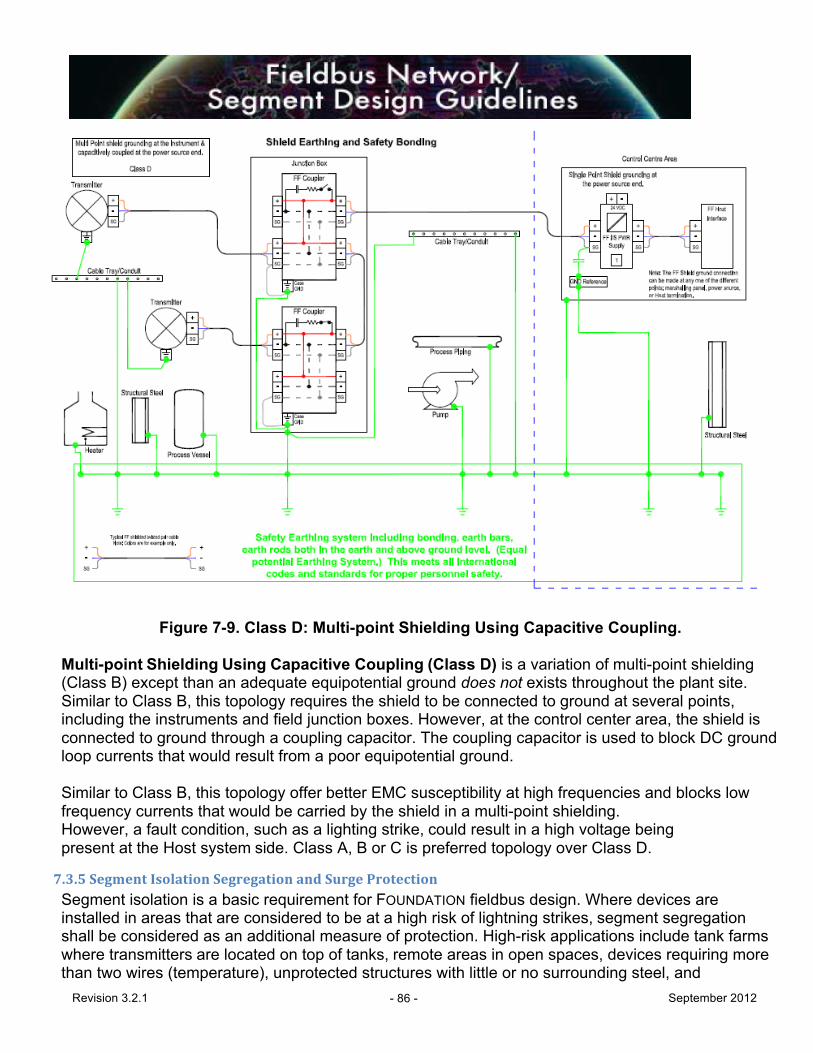
Revision 3.2.1 - 86 - September 2012
Figure 7-9. Class D: Multi-point Shielding Using Capacitive Coupling.
Multi-point Shielding Using Capacitive Coupling (Class D) is a variation of multi-point shielding (Class B) except than an adequate equipotential ground does not exists throughout the plant site. Similar to Class B, this topology requires the shield to be connected to ground at several points, including the instruments and field junction boxes. However, at the control center area, the shield is connected to ground through a coupling capacitor. The coupling capacitor is used to block DC ground loop currents that would result from a poor equipotential ground. Similar to Class B, this topology offer better EMC susceptibility at high frequencies and blocks low frequency currents that would be carried by the shield in a multi-point shielding. However, a fault condition, such as a lighting strike, could result in a high voltage being present at the Host system side. Class A, B or C is preferred topology over Class D.
7.3.5 Segment Isolation Segregation and Surge Protection
Segment isolation is a basic requirement for FOUNDATION fieldbus design. Where devices are installed in areas that are considered to be at a high risk of lightning strikes, segment segregation shall be considered as an additional measure of protection. High-risk applications include tank farms where transmitters are located on top of tanks, remote areas in open spaces, devices requiring more than two wires (temperature), unprotected structures with little or no surrounding steel, and
Revision 3.2.1 - 87 - September 2012
transmitters that are located on the top of columns or in the open on top of structures.
7.3.5.1 Isolation
FOUNDATION power supplies shall be applied with galvanic isolation between power source, ground and the segment. Galvanic isolation is required for all field devices and H1 interface cards. Isolating spur protection is generally not required. The most common couplers for non-IS installations provide simple analog current limiting for short circuit protection with no isolation. Couplers do not provide lightening protection.
7.3.5.2 Segregation
Transmitters that are at higher risk of direct strike or near miss may be placed on separate segments with no final control elements. In general, the consequences of a transmitter loss will be much less than the process upset or trip consequences resulting from damage to a segment with final control elements. In this case, the risk associated with the transmitter loss does not justify the installation of surge protectors.
7.3.5.3 Surge Protectors Installations where lightning is frequent, grounding is poor, and exposure is high offer more extreme challenges for lightning protection. This may occur at tank farms, remote areas, or exposed sites in operating units. For installations with high risk of lightning strikes and where devices are used for control or associated with a control loop, the following additional measures should be considered:
Surge protection installation: When surge protectors are applied, they shall be installed at each field device on the segment, and at the host H1 interface. The number of devices on a segment should be kept low and confined to a small area (<30 m2).
It is vitally important that the surge suppression device does not measurably attenuate the fieldbus signal.
Spur protection with surge protectors: Current-limiting couplers should not be used in combination with surge protectors. The surge protectors will cause failure of the current limiting circuits when a lightning strike occurs—even when the lightning strike is not a direct hit.
The decision to use device spur surge protection must be risk-ranked against the exposure to the segment due to no spur over-current protection. The results of the risk ranking shall be documented for future reference.
Commentary: The need for surge protection versus the need for short circuit protection on a segment may significantly alter the segment loading (device assignment). Care should be taken to ensure the best result for the particular installation. Current-limiting and segment segregation generally provide the lower risk than surge protectors (which preclude current limiting).
7.3.6 Terminators
All terminators located in the field shall be installed in a junction box or on a device coupler. Terminators should not be installed in FOUNDATION fieldbus devices.

Revision 3.2.1 - 88 - September 2012
Commentary: A cable signal encountering a discontinuity, such as a wire open or short, produces a reflection. The reflection is a form of noise that distorts the original signal. A terminator, consisting of a capacitor in series with a resistor, is used at the ends of a fieldbus cable, to prevent a reflection. Care should be taken if a multi-port H1 interface does not support disabling individual ports. All ports may require segment terminators to be installed (an equivalent segment).
7.3.7 Repeaters Repeater functionality to extend the length of a fieldbus segment is not normally needed or recommended. If an active repeater must be used, consideration should be given for the following:
• Redundancy • Failure mechanisms • External power requirements • Segment device count and loading • Termination requirements (both sides) • Timing through-put delays
Sometimes repeater functionality may exist in combination with IS Isolation for use in IS power supplies or IS isolated device couplers, which would have application specific requirements. Commentary: Repeaters replace one of the field devices in the physical device count, allowing the addition of the equivalent of an entire new segment. By adding a repeater, a new segment is created. Repeaters can be used to split a network into smaller segments.
If a repeater is added to the network, a new segment is connected, and the following should apply:
• The newly created segment should have terminators at both ends. • Timing limits the maximum number of repeaters in series to four (4) on a segment.
7.4 FOUNDATION Fieldbus Segment Risk Management Although optional, each end-user facility should identify and document a risk assessment philosophy (method) by which fieldbus devices are assigned to network/segments. This is not to be confused with Safety Integrity Level evaluations, or other safety-related design. The use of registered devices and wiring components is an essential part of Risk Management.
The Segment Design Risk Assessment is an operability review process performed prior to FOUNDATION fieldbus segment design (See Section 2.4.2). The segment design process may use existing segment loading methods or the methodology described in Appendix 4. The philosophy shall consider network/segment segregation, multiple segments per H1 interface, etc. Any form of risk assessment or ranking should be clearly shown on

Revision 3.2.1 - 89 - September 2012
the network/segment drawings or other project documents. Topology design should minimize single points of failure.
7.5 Segment Design Considerations
7.5.1 Multivariable Devices
Multi-input and multivariable transmitters employing FOUNDATION Analog Input (AI) Function Block(s) may be used for control and monitoring. A multivariable transmitter input should be used in one control loop only. All other variables from the transmitter can be used for monitor-only applications.
Multi-input transmitters using FOUNDATION fieldbus Multiple Analog Input (MAI) Function Block(s) shall be used for monitor only applications. Commentary: MAI blocks do not utilize scheduled publish/subscribe communications (compel data) and, therefore, do not offer the security of stale data counters in control blocks.
7.5.2 Discrete Devices Discrete fieldbus devices (using DI/DO Function Blocks) may be used on the same network/segment as regulatory control and monitoring devices.
7.5.3 Network/Segment Shorting A shorted network/segment or power supply failure will send spring loaded valves to their designated failure position, regardless of the device hosting the PID algorithm.
7.5.4 Transmitter Assignment
Normal practice shall be to include the transmitter with the primary process variable on the same segment with its associated valve. Commentary: This is a necessary condition to allow for field-based control. This restriction does not apply for systems supporting bridge capability between H1 networks.
7.5.5 Multiple Process Variables
Multiple measurements used to provide a calculated differential shall be assigned to a common segment with the differential calculation performed in one of the transmitters as they typically have a lower “load” than an output device. Commentary: This restriction does not apply for systems supporting bridge capability between H1 networks.
7.5.6 Device Diagnostic Alarms Most diagnostic alarms from field devices require no immediate operator action. These alarms shall be logged (auto acknowledge, no horn) for future analysis and action by maintenance personnel. These diagnostic conditions shall also be indicated in maintenance diagnostic screens with a means of easy navigation to indications of root cause and corrective action.

Revision 3.2.1 - 90 - September 2012
7.5.7 Device Segregation
Segment design shall be such that loss of a segment does not affect more than one of the parallel (redundant/spare) process units or equipment items. Segregate segments by piece of equipment. For example, do not combine bottom-level control for different columns on one segment even though they are geographically close together.
• Installing redundant bus/host system interface cards avoids the possibility of a common-mode failure that could fail several buses at the same time when multiple buses are installed on a single interface card. Minimize communications between networks.
• Ensure control communications remain deterministic (cyclic). Devices that operate together shall be on the same segment in order to:
An example of this configuration is the use of a FOUNDATION fieldbus in a PID field configuration and/or cascade loops. Equipment with redundant transmitters for the same process measurement point shall be distributed to reside on separate H1 segments. However, multiple measurements used to provide a calculated value shall be assigned to a common segment. An example would be separate pressure transmitters used to calculate a differential, where the differential calculation is performed in one of the transmitters (See Section 5.5.1 for fault handling).
7.5.8 Combining Safety and Control on a Segment In general, control and safety should be kept separated. The complexity (cost) of managing both types of signals on the same segment is not worth the risk and could be much more expensive than keeping applications separate. In any case, separation guidelines in IEC 61511 must be observed. One use case for mixing signals is offered here and two methods of satisfying this use case example are given. The use case is for a safety interlock to be able to override a control valve. No preference is stated or implied for one of these solutions. These are provided only to illustrate a point—not as recommendations.
Solution 1: Provide a solenoid on the control valve to provide the interlock override. The solenoid can be actuated from the safety system without interfering with control functions.
Solution 2: Provide a serial link from the safety system to the control system to allow the control system to override control and place the loop in a proper initialization state.
7.6 Limited Power Installations There are several methods for limiting power for installations in classified areas. These include:
• High power trunk with current limiting device couplers (non-incendive) • High power trunk with isolating device couplers (intrinsically safe) • FNICO (Fieldbus Non-Incendive COncept) non-incendive bus limited power (now known
as FISCO ic) • FISCO (Fieldbus Intrinsically Safe COncept) intrinsically safe bus limited power • IS Entity Concept intrinsically safe bus limited power
Revision 3.2.1 - 91 - September 2012
Commentary: For explosion proof installations, remember that you may have to power down an entire segment to perform maintenance on a device.
7.6.1 Fieldbus Intrinsically Safe Installations In general, the design of IS fieldbus installations must follow the same guidelines as imposed by the technology for non-IS installations. The major differences are the power constraints imposed by the need to remain intrinsically safe and the requirement to use suitably certified power supplies, field instruments and wiring components. For IS applications, cable should:
• Comply with IS inductance and capacitance limitations, as specified in the approvals documentation. For FISCO installations, additional requirements apply to the resistance characteristics of the cable.
• Be identified as carrying intrinsically safe circuits. This may be by means of marking or the use of a colored sheath.
Commentary: Typically, IS wiring has a light blue outer jacket.
7.6.2 FISCO
The FISCO concept has been developed to provide a means of supplying additional power to the network/segment while still keeping the energy level below that which could cause an explosion. Due to the limited DC power to be shared by a number of field devices, long cable runs and terminators storing capacitive energy, the traditional intrinsic safety installation and interconnection rules restrict the application of Intrinsically Safe (IS) systems. The key advantages of FISCO, compared with systems installed according to the conventional FF-816 “Entity” concept, are:
• Higher bus current, allowing more field devices per segment • Elimination of cable parameter calculations • Simplification of the safety documentation—just a list of devices • Addition of new devices without reviewing the safety case
Power supplies, terminators, cable and field instruments for use in FISCO systems must comply with the requirements of Table 7.1, as defined in IEC Technical Specification IEC TS 60079-27. Where the individual components have been designed and certified according to these requirements and carry FISCO marking where appropriate, they may be assembled without further approval of the overall combination. The criterion for such interconnection is that the voltage (Ui), the current (Ii) and the power (Pi), which the intrinsically safe apparatus can receive and still remain intrinsically safe, considering faults, must be equal or greater than the voltage (Uo), the current (Io) and the power (Po) which can be delivered by the associated apparatus (power supply unit). In addition, the maximum unprotected residual capacitance (Ci) and inductance (Li) of each apparatus (other than the terminators) connected to the fieldbus must be less than or equal to 5nF and 10µH respectively.

Revision 3.2.1 - 92 - September 2012
In each IS segment, only one active device—normally the associated apparatus (power supply)—is allowed to provide the necessary power for the fieldbus system. The allowed voltage (Uo) of the associated apparatus used to supply the bus is limited to the range of 14 to 17.5 Vdc. All other equipment connected to the bus cable has to be passive, meaning that except for a leakage current of 50 µA for each connected device, the apparatus is not allowed to provide energy to the system.
Table 7.1 FISCO Parameters
EEx ia IIC (Groups A-D) EEx ib IIB (Groups C,D)
Power supply Trapezoidal output characteristic
Rectangular output characteristic
Uo 14 -‐ 17.5 V
Io In accordance with IEC 60079-‐11 but not exceeding 380 mA
Po In accordance with IEC 60079-‐11 but not exceeding 5.32 W
Cable
Cable length, trunk 1000 m max.
5000 m max. Note 1
Cable length, spur 60 m max. Note 2
Loop resistance R‘ 15 -‐ 150 Ω/km
Loop inductance L‘ 0.4 -‐ 1 mH/km
Capacitance C‘ 45 -‐ 200 nF/km Note 3
C' = C'conductor/conductor + 0.5 C'conductor/screen if the bus circuit is potential-free (balanced) C' = C'conductor/conductor + C'conductor/screen if the screen is connected with one pole of the supply unit Field device
Ui 17.5 V min. Ii 380 mA min. Pi 5.32 W min. Classification EEx ia IIC or Ex ib IIC (Groups A-D), T4 Maximum number of field devices
32
Internal capacitance
5 nF max. Internal inductance
10 µH max.

Revision 3.2.1 - 93 - September 2012
Terminator 80 - 120 Ω 0.8µF - 1.2µF (limited by FF specification)
Note 1. Limited to 1,900m by FOUNDATION fieldbus. Note 2. IEC/TS 60079-27 has a limit of 30 m; this has been increased to 60 m in IEC draft 60079/27 Ed.1/CDV, and the 60 m value is likely to be adopted in the final standard Note 3. IEC/TS 60079-27 has a lower limit of 80 nF/km; this has been relaxed to 45 nF/km in IEC draft 60079/27 Ed.1/CDV, and the 45 nF value is likely to be adopted in the final standard
7.6.3 FISCO ic (Formerly Known as Fieldbus Non-Incendive Concept (FNICO) Installations
It should be noted that FNICO is now known as FISCO ‘ic’. FISCO ic is a derivative of FISCO and is specifically intended for fieldbus installations in Zone 2 and Division 2 hazardous areas. It takes advantage of the relaxed design requirements for non-incendive (energy-limited) circuits compared with those for intrinsic safety. FICSO ic enjoys the same benefits as FISCO in terms of simple safety documentation and the elimination of cable parameter calculations, and retains the ability to connect and disconnect the field wiring in the hazardous area while under power and without “gas clearance” procedures. FISCO ic also has the following additional benefits compared with FISCO:
• Higher levels of bus current, allowing more devices to be connected to the hazardous area trunk
• Easier selection of approved field devices. Suitable devices include EEx nL, non- incendive, IS (Entity) and IS (FISCO)
• Installation rules for non-incendive wiring are less onerous than those for intrinsic safety The requirements for FISCO ic systems are defined in IEC draft document 60079-27 Ed.1/CDV, and are expected to emerge in the final IEC 60079-27 standard, together with the requirements for FISCO.
The design requirements for FISCO ic power supplies, field devices, cable and terminators are essentially the same as those for FISCO, except in the following respects:
• Field wiring is classified as EEx nL in accordance with IEC 60079-15, or North American non-incendive
• Maximum permissible value of Io is 570 mA • Field devices may have a maximum of 20 µH internal capacitance, thereby
permitting IS “Entity” certified field devices to be used in FISCO ic installations
7.6.4 High-power Trunk Installations High-power trunks allow full utilization of maximum segment length and device capacity without limitations due to power restriction. These designs are generally more economical than FISCO, FISCO ic and Entity. High-power trunks may be used in Zone 1 or 2 installations to:
• Supply power to non-incendive spurs in Zone 1 or 2 (requires current limiting couplers as shown in Figures 7.6, 7.7 and 7.9)
• Supply power to IS spurs in Zones 0, 1 or 2 (requires current-limiting couplers

Revision 3.2.1 - 94 - September 2012
as shown in Figure 7.8)
7.6.5 High-power Trunk with Current Limiting Device Couplers (Non-Incendive)
If using non-incendive wiring practices with current limiting device couplers, all equipment should have appropriate zone ratings.
7.6.6 High-power Trunk with Isolating Device Couplers (Intrinsically Safe)
If using intrinsically safe wiring practices with isolating device couplers, all equipment should have appropriate zone ratings.
7.7 FOUNDATION Fieldbus Loading and Calculations Allowable network and segment loading is determined by the lower value of four parameters:
• Risk management criteria (Section 7.4) • Spare capacity (Section 7.7.1) • Segment execution time (Section 7.7.2) • Voltage drop calculations (Section 7.7.3)
7.7.1 Spare Capacity The maximum number of devices on any segment (including future devices) should be no greater than 12. Project staff shall set a design standard for the maximum number of devices per segment for that project if less than 12. This design standard shall be used as the basis for voltage drop calculations and shall include spare capacity for future expansion. Spare capacity for a segment is to be calculated based upon two conditions, with the largest number of spare devices to be used for sizing:
• Spare capacity should be defined as 20%. Therefore, if the maximum number of field
devices per segment for a project is 12, taking into account spare capacity for future expansion, the maximum number of devices to be installed into a segment shall be 10 at the start of the project.
• In all cases, segments shall be designed with adequate spare capacity for the future addition of one control loop (e.g., one transmitter and one final element). Therefore, each segment shall be designed for a minimum of two future devices.
In addition, the segment macrocycle shall be designed for this future device allowance as described above. That is, the macrocycle shall allow one transmitter to be added (AI) and one valve positioner (final element) to be added (AO) and still ensure that the minimum free time is met (see section 7.7.2). This is based on a single macrocycle with default duration of one second. Requirements for fast execution that may conflict with this directive shall be approved by the principal. In all spare capacity calculations, the impact on the power requirements, design of the field junction box, segment bandwidth constraints, etc. shall be considered and sized to allow the present and future number of devices per segment. Commentary: Each Host system is different in the limitations on the number of parameters communicated to/from a segment within a given time, and hence shall be also considered in the design of spare
Revision 3.2.1 - 95 - September 2012
segment capacity. The maximum number of VCRs allowed per segment is less of an issue with modern day Host systems, but may be an issue in older versions.
7.7.2 Segment Execution Time A Link Active Scheduler (LAS) is a deterministic, centralized bus scheduler that maintains a list of transmission times for all data buffers in all devices that need to be cyclically transmitted. The LAS, residing in the H1 interface cards, is responsible for coordinating all communication on the fieldbus (it is in charge of the token). The cycle communication is executed at fixed intervals called a macrocycle. Segment macrocycles should match the execution times in the controller. The macrocycle should have a minimum of 50% unscheduled (free asynchronous) time (see Section 4.4). Typical macrocycle time is 1 s. Commentary: By exception, a faster macrocycle may be set (500 or 250 msec), but this will impact the other segment design parameters such as default number of devices on that segment. Alternatively, longer macrocycles are possible. The principal shall approve such deviations from the default macrocycle time based on a dedicated segment assessment. Loop execution time must take the location of the PID (field or Host) into consideration. Do not mix control loops or control strategies with different macrocycle times (1 sec. vs. 0.25 sec.) on the same network/segment. Mixing of macrocycle times can lead to schedules that may not be within the capability of some link masters.

Revision 3.2.1 - 96 - September 2012
Commentary: Having different macrocycles on the same network are also likely to make it difficult to diagnose communications problem should they occur in the future, especially if they are sporadic in nature. Some Host systems also enable multi-scheduling within a macrocycle. Multi-scheduling allows selected loops to run faster than the macrocycle. The principal shall approve multi-scheduling, as it will reduce the number of devices per segment depending on the applied schedule. For segments that only monitor measurements, limit segment to 12 devices. Commentary: A signal multiplexer shall be treated differently with the maximum number of multiplexers allowed on a segment based upon the Host system constraints. In all cases, the number of signal multiplexers shall not exceed the field device equivalents provided. The suggested maximum numbers of devices per segment for the following listed macrocycle times are as follows:
• For loops requiring 1 s macrocycle time, limit segment to 12 devices including 3 valves maximum
• For loops requiring 0.5 s macrocycle time, limit segment to 6 devices including 2 valves maximum
• For loops requiring 0.25 s macrocycle time, limit segment to 3 devices including 1 valve maximum
Commentary: For FOUNDATION for SIF segments, extra restrictions apply for stale count and extra communication time is required for black channel communication. These considerations may further restrict the number of devices allowed on a single segment. Calculation examples will be provided in a future revision.
7.7.3 Voltage Drop Calculations
Voltage drop calculations for segments shall be checked against basic rules. Only extreme segment configurations should be validated to serve as design boundaries. All other segment configurations less than the extreme cases can be assumed to have no voltage drop issues. For long home runs, use 1.13 mm2 (16-gauge) cable with 100 Ω +/- 10 Ω nominal impedance.

Revision 3.2.1 - 97 - September 2012
Table 7.2
Step 1 - Calculation of Segment Current Draw from FOUNDATION fieldbus Power Supply for Non IS-Based Wiring
Item
Value Running Total
Comments
1 Number of devices per segment
12 Maximum number of devices per segment. Project staff may set a lower maximum limit.
2 Average current demand per device
20 mA 20 mA is a typical value
3 Total current draw due to field devices
12 * 20 mA
0.24 A Total current due to 12 devices assuming each device requires 20 mA.
4 Current draw of FOUNDATION™ Fieldbus termination block (in field junction box)
5 mA 0.245 A The value is Manufacturer dependent. Validate the current draw for the equipment being used.
5 Current draw of FOUNDATION™ Fieldbus termination block when in current limit for one spur
60 mA 0.305 A The value is Manufacturer dependent. Validate the current draw for the equipment being used.
6 Current draw of diagnostic tool
20 mA 0.325 A Ensure that the use of a diagnostic tool does not result in voltage at a device becoming too low.
7 Current draw of H1 interface card to the segment
40 mA 0.365 A Account for redundant H1 interface cards (treat each card like a field device -‐ 20 mA)
8 Total anticipated current from the FOUNDATION™ Fieldbus power supply for segment of interest.
0.365 A Ensure that the H1 power supply is capable of supplying this current load.

Revision 3.2.1 - 98 - September 2012
Table 7.3 Step 2 - Determine Voltage Drop Due to Homerun Cable (Voltage at Field Junction Box) for a
Non IS-Based Design
Maximum ambient temperature of the cable should be considered because a temperature difference of 30° C increases the load resistance by more than 10%.
Case 1: Standard FOUNDATION Fieldbus Cable – Typical Cable Specifications Used.
Item
Value Running Total
Comments
9a Voltage Present at H1 card
24 VDC Typical value for FF power supplies. Replace with correct value for power supply being used.
10a Cable electrical specifications
0.8 mm2 (18 gauge)
21.8 W/km
Value can be found from the Manufacturer's wire specifications
11a Length of Home Run 500 m (1640 ft)
Adjust this value to project specific case. The worst case shall be examined only to determine design boundaries.
12a Total wire length of segment (2 x length)
1000 m (3280 ft)
Round trip for the current equals two times the home run length.
13a Total resistance of segment home run
21.8 W 1000 m * (1km/1000 m) * (21.8 W/km)
14a Current draw of field side downstream of H1 interface card
0.365 A This is the total load on the segment as calculated in step 8
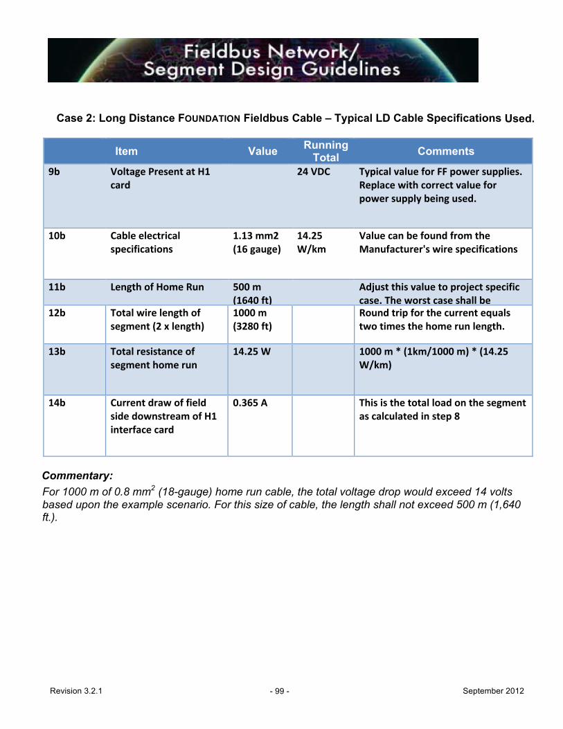
Revision 3.2.1 - 99 - September 2012
Case 2: Long Distance FOUNDATION Fieldbus Cable – Typical LD Cable Specifications Used.
Item
Value Running Total
Comments
9b Voltage Present at H1 card
24 VDC Typical value for FF power supplies. Replace with correct value for power supply being used.
10b Cable electrical specifications
1.13 mm2 (16 gauge)
14.25 W/km
Value can be found from the Manufacturer's wire specifications
11b Length of Home Run 500 m (1640 ft)
Adjust this value to project specific case. The worst case shall be examined only to determine design boundaries.
12b Total wire length of segment (2 x length)
1000 m (3280 ft)
Round trip for the current equals two times the home run length.
13b Total resistance of segment home run
14.25 W 1000 m * (1km/1000 m) * (14.25 W/km)
14b Current draw of field side downstream of H1 interface card
0.365 A This is the total load on the segment as calculated in step 8
Commentary: For 1000 m of 0.8 mm2 (18-gauge) home run cable, the total voltage drop would exceed 14 volts based upon the example scenario. For this size of cable, the length shall not exceed 500 m (1,640 ft.).
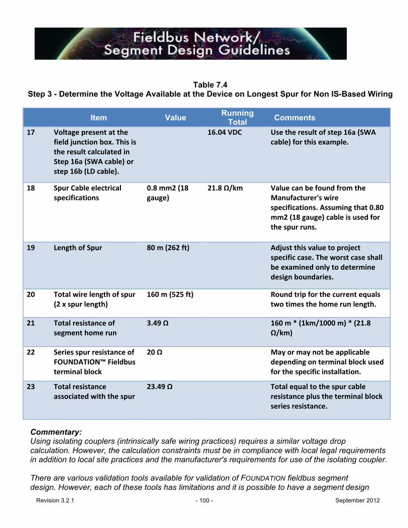
Revision 3.2.1 - 100 - September 2012
Table 7.4 Step 3 - Determine the Voltage Available at the Device on Longest Spur for Non IS-Based Wiring
Item
Value Running Total
Comments
17 Voltage present at the field junction box. This is the result calculated in Step 16a (SWA cable) or step 16b (LD cable).
16.04 VDC Use the result of step 16a (SWA cable) for this example.
18 Spur Cable electrical specifications
0.8 mm2 (18 gauge)
21.8 Ω/km Value can be found from the Manufacturer's wire specifications. Assuming that 0.80 mm2 (18 gauge) cable is used for the spur runs.
19 Length of Spur 80 m (262 ft) Adjust this value to project specific case. The worst case shall be examined only to determine design boundaries.
20 Total wire length of spur (2 x spur length)
160 m (525 ft) Round trip for the current equals two times the home run length.
21 Total resistance of segment home run
3.49 Ω 160 m * (1km/1000 m) * (21.8 Ω/km)
22 Series spur resistance of FOUNDATION™ Fieldbus terminal block
20 Ω May or may not be applicable depending on terminal block used for the specific installation.
23 Total resistance associated with the spur
23.49 Ω Total equal to the spur cable resistance plus the terminal block series resistance.
Commentary: Using isolating couplers (intrinsically safe wiring practices) requires a similar voltage drop calculation. However, the calculation constraints must be in compliance with local legal requirements in addition to local site practices and the manufacturer's requirements for use of the isolating coupler. There are various validation tools available for validation of FOUNDATION fieldbus segment design. However, each of these tools has limitations and it is possible to have a segment design

Revision 3.2.1 - 101 - September 2012
that will not validate. Care shall be taken in using these tools; understand the manufacturer's disclaimer on their use.
7.7.4 Fieldbus Attenuation Calculation Although the example calculation above and some of the segment validation tools do not calculate signal attenuation for a segment design, it is another aspect that needs confirmation. Signal attenuation is calculated similar to voltage drop taking into account the attenuation due to the cable and due to each device, and ensuring the total attenuation is less than the allowable according to the FOUNDATION fieldbus specification (13.98 dB). A validation tool with an attenuation calculation feature can be used to determine boundaries for segment design (validation of worst case attenuation). The 1900 m limit (spur + trunk) recommended by IEC 61158-2 is a good practical limit for field installations. End-user approval is required for longer runs. Commentary: The distance may be theoretically possible, but there are other factors that have to be considered such as signals becoming distorted as they travel on the cable. While H1 signals have been transmitted over twisted-pair well in excess of 2 km under ideal noise conditions, this is not a recommended practice. Normally, the power voltage drop due to the resistance in the wire will become a limitation before attenuation factors will become significant.
7.8 FOUNDATION Fieldbus Network/Segment Naming Convention A consistent method for identifying all signal wires is required in any control system; this is especially true for a FOUNDATION fieldbus system. Depending on project work processes and or schedule, different numbering systems may be employed. A preferred system is shown in the paragraphs below. However simpler sequential numbering systems for segments may be utilized when controller assignments are not known until late in the project. The implemented naming convention should apply to all project elements including FOUNDATION fieldbus. The application of fieldbus introduces new components (segments, spurs, etc.) that need to be captured in the applied naming convention. The following examples are given:
7.8.1 Segment Naming Convention
• FOUNDATION fieldbus segments, ##-NN-MM-P where: – ## - indicates the plant number, or abbreviated name to which the segment is
connected – NN - indicates node or controller number – MM - module number – P - segment or port number
Example: CCG-01-20-P01 would represent a segment located at the CCG process unit, on controller 01, H1 card number 20, and port 01.

Revision 3.2.1 - 102 - September 2012
7.8.2 Loop and Instrument Naming Convention Loop and instrument tagging convention shall follow location/project guidelines.
7.8.3 Spur Naming Convention All spurs shall be labeled with the instrument tag name and follow the standard location and project guidelines.
Revision 3.2.1 - 103 - September 2012
8.0 SITE INSTALLATION GUIDELINES
8.1 Introduction FOUNDATION fieldbus technology requires a greater emphasis on system configuration and management than testing of individual devices. Therefore, instrument technicians doing loop checking will require the following:
• Training on the systems and technology that are being used • Test equipment in accordance with Section 8.4
Fieldbus commissioning, being part of a computer network, requires a high level of communications between the instrument/control engineers and the maintenance technicians. Configuration of the field devices shall be carried out from the Host system fieldbus configuration software. This is in the interest of building the database as commissioning proceeds.
• System management support. A DCS manager shall be appointed who is responsible for the DCS system configuration while construction and check-out work is ongoing. – Specialist support for the systems involved.
Procedures for commissioning of a FOUNDATION fieldbus system include:
• Cable continuity, grounding, and insulation tests • Field device (physical installation) • Device coupler • Fieldbus power supply • Field device connection and signal analysis • Device download/software checks (data reconciliation) • Optional bus monitor capture • Optional scope waveform capture
8.2 Network Installation The construction contractor should take care when installing the fieldbus wire networks. Listed below are the steps to be taken during the installation.
8.2.1 Initial Cable Checkout It may be advisable to test the reel of fieldbus cable to verify cable integrity before installation. Experience has shown that new cable irregularities are so infrequent that it is more efficient to check cable after installation according to the cable test procedures in this section.
8.2.2 Cable Installation
• Install the trunk cable (longest cable of the fieldbus network). • Install terminators at both ends of trunk cable. Terminators are not to be installed on a
device but on a device coupler. Terminators are to be clearly marked. • External terminators on the proper terminals in device couplers. • Install any spur lines to the trunk cable.

Revision 3.2.1 - 104 - September 2012
• Perform cable resistance and grounding tests (See Section 9.5.3, Appendix 5) • Connect Fieldbus power supply, grounds, and H1 interface to the trunk cable. • Perform Segment Test Procedure (See Section 8.5.3, Appendix 5) • After completing the segment test procedure, the devices can be commissioned.
Commentary: If terminators are installed with or in a device, they may be inadvertently removed when a technician is servicing a device and hence affect the entire network.
8.3 Fieldbus Segment Commissioning Form A Fieldbus Segment Commissioning Form shall be completed for each segment (see Appendix 5, Table A5.1).
8.4 Test Equipment The instrument construction contractor shall provide test equipment required to perform configuration, calibration, and loop checks. Commentary: FOUNDATION fieldbus instruments should not be calibrated because they are more accurate than most test equipment. FOUNDATION devices shall have their ranges and scales downloaded from the DCS after the device is connected to the segment. Dedicated fieldbus tools shall be applied in addition to the standard test equipment used for commissioning devices. Commentary: The following FOUNDATION fieldbus test equipment can be considered as minimum (the user is encouraged to explore other products which are available or are being developed):
• Relcom FBT-6 fieldbus monitor or the Pepperl+Fuchs segment tester • Rosemount 375/475 Field Communicator • Valve benchmark equipment/software • Ungrounded 200 MHz oscilloscope (segment trace capture, and segment troubleshooting).
The Pepperl+Fuchs tester has built-in oscilloscope functionality for troubleshooting. For projects with several commissioning teams, a sufficient number of test equipment should be available to enable fast commissioning. It should be noted that the Pepperl+Fuchs segment tester, Relcom FBT-6 and Rosemount 375/475 handheld provide various types of diagnostic information, which may require a higher level of expertise to use effectively. These tools should be used by dedicated teams for complex device commissioning and troubleshooting.
8.5 Installation of FOUNDATION Fieldbus Instruments and Wiring
8.5.1 Wiring Splices and wire nuts shall not be allowed in instrumentation wiring circuits. Wiring terminations shall be made at terminal strips.

Revision 3.2.1 - 105 - September 2012
When pre-molded cable is used, coupler and fieldbus device ports shall be protected with temporary plastic plugs prior to cable installation to prevent damage due to water, sand, dirt, etc. Contractor should not install spurs until both the coupler and the field device have been installed. Minimum cable bend radius shall not be exceeded for all installations. Excess wire that occurs with pre-terminated fieldbus cables may be coiled. Tie wraps can be used to secure the excess cable. Care should be taken not to pinch the wire with the cable tie. Install individual cables to the field instruments. Complete wire tagging and wire terminations for these individual cables. Avoid sloppy shielding. The use of heat shrinkable tubing instead of tape is the preferred method for isolating the shield at the signal wire terminations.
8.5.2 Instrument Ground System The instrument ground system shall be inspected to verify that it has been installed according to the installation drawings (See Figures 7-6 through 7-9).
8.5.3 Segment Checkout and Commissioning Installation of wiring shall be carried out according to the procedure detailed below and requires the completion of the field wiring (trunk and spurs) before trunk wiring is connected to the FOUNDATION fieldbus power supply.
o Install trunk cables, making sure that cable tags are installed. Check wiring for the proper color code. Tag and terminate the trunk cable in the field junction box.
Tag and terminate the trunk (segment) wiring at the fieldbus power supply plug, but DO NOT PLUG INTO THE FIELDBUS POWER SUPPLY AT THIS TIME. The segment will be powered up after Step 1 of Table A5.1 is complete. The trunk cables shall not be connected to the fieldbus power supplies until all devices on the segment have been properly terminated.
o Perform the resistance tests for each segment according to Table A5.1 Step 1. Commentary: Table A5.1 is applicable to non-isolated couplers. If isolated couplers are being utilized, a separate procedure shall be developed to test the associated FOUNDATION fieldbus segments.
• Power up the segment by plugging the segment into the fieldbus power supply (See Table A5.1 Step 2). Log the shield to ground bus bar resistance. Care shall be taken to ensure that no signal conductor becomes grounded, since the system is now powered.
• Capture the segment diagnostics files with clip-on segment test tools (e.g., Pepperl+Fuchs tester, FBT-6, etc.) per Table A5.1 Step 3. The diagnostics files shall be saved and combined into a master document as a deliverable record.
• For segments with isolated coupler, the previous two steps must be repeated for each spur prior to proceeding to the next step.

Revision 3.2.1 - 106 - September 2012
• Capture segment trace file with clip-on segment test tools (optional per project) in accordance with Table A5.1 Step 4. The segment trace files shall be saved and combined into a master document as a deliverable record.
Commentary: Segment trace files shall be retained for historical reference to aid in possible future troubleshooting. They are not intended for segment acceptance. Segment acceptance will be primarily based on conformance to the measurement requirements in Table A5.1.
• The DCS Manager or his delegate shall download all devices (e.g., all blocks – Function Blocks and Transducer Blocks) on a segment. The project shall establish procedures for data reconciliation for Resource and Transducer Blocks.
Commentary: This procedure assumes that the instrument has its tag name pre-configured from vendor. A device that does not have a tag will require connection one at a time to make sure that it is communicating with the right device. The FAT will have verified device Function Blocks, but Resource and Transducer Blocks will require data reconciliation. Some vendors have not resolved data reconciliation procedures where Host system data is downloaded over the top of configuration that has been factory entered into the device. For each project, data reconciliation procedures (e.g. spreadsheet comparison, frozen device parameters) shall be established that are specific for the Host system and devices used on that particular project.
• At this time, commissioning of the fieldbus segment is complete. Check the device and segment health using the diagnostics on the Host system and clear the error counts (if applicable). All above diagnostic activities shall be completed before the loop-check process can begin on a segment. The procedures for assuring segment and device health are vendor-specific, but shall be performed before proceeding to further steps. The owner’s representative shall perform this task.
Commentary: The Host system diagnostic check should be repeated after a period of time (nominally one week) to monitor any accumulation of error counts if applicable.
• Proceed to pre-loop check

Revision 3.2.1 - 107 - September 2012
9.0. ACCEPTANCE TESTING REQUIREMENTS
9.1 Introduction
This section describes the various Acceptance Testing requirements of the FOUNDATION fieldbus portion of a DCS or Host system. This may consist of Factory Acceptance Testing (FAT), Device Integration Testing, Site Acceptance Testing (SAT) and Segment Testing/Commissioning. Sample procedures and requirements may be found in Appendix 8 (Acceptance Testing Procedures) and Appendix 5 (Fieldbus Segment Testing Documentation). Commentary: Depending on the project and the experience level of the user, these testing requirements may be implemented separately or combined to allow the user to provide the most efficient method to verify the FOUNDATION fieldbus aspects of the project. Experienced users may defer some of these procedures and use simulation applications during design and checkout hardware in the field. Some projects may be of modular construction in which small portions of the plant are prefabricated. These can be “packaged units” or larger areas of the plant built in a remote module yard and then shipped to the plant site. With the testing equipment and Host system options now available, the user has several options available for testing and acceptance.
9.2 Assumptions The testing procedures assume that the following:
• The manufacturer, in accordance with their standard procedures, has performed pre- testing of all types of field devices with the host system. These procedures are executed at the manufacturer’s premises and are described in separate documents, which should be available for review during the testing and form a part of the overall set of test documents.
• Any deficiencies observed in the manufacturer’s pre-FAT or hardware testing have been resolved.
• Adequate FOUNDATION fieldbus expertise and professional knowledge is available to support the test and to implement corrective actions if required. This may require both Host and device manufacturer representatives.
• For all testing other than Device Integration Testing: – Host configuration and graphics have been completed per customers' specification
with the appropriate FOUNDATION fieldbus Function Blocks assigned to the appropriate fieldbus devices.
– FOUNDATION fieldbus device tags (including the fieldbus addresses) corresponding to the host configuration above have been configured.
– Sufficient devices are available to configure all typical networks. A selection of representative FOUNDATION fieldbus segments is available. Purchaser shall confirm the selected segments as being representative of the networks being installed. In addition, segments with the highest device load, communication load, and complex strategies shall be included.

Revision 3.2.1 - 108 - September 2012
– Selected FOUNDATION fieldbus networks/segments are prepared (but no devices connected). The hardware infrastructure will be checked (e.g. power, signal strength, noise and grounding).
– FOUNDATION fieldbus simulation function for parameters in field devices can be enabled to simulate process conditions and to evaluate alarm settings, but is not recommended because the simulation feature can be left on inadvertently. Use the manual feature of the Function Blocks and enter a value. Simulation shall be turned off as a default for commissioning. Some asset management systems will report simulation-on as an alert/alarm.
– Sufficient external terminations of the type used by the project are available. – Final cabling and junction boxes are not used. Representative connections will be
made. The final infrastructure will be tested during the commissioning. Commentary: For especially long or complicated networks, the network should be simulated using reels of cable in the factory or a cable simulator, in order to more closely emulate expected field conditions.
9.3 Device Integration Testing Requirements: Device Integration Testing verifies that the selected FOUNDATION fieldbus field devices and wiring components are truly compatible with the Host system (and software revision) selected and with each other. Sufficient operation time should be allowed to ensure stability of all devices. Device Integration Tests are especially useful in the early stages of a project when selecting the Host system and field devices to be used and developing configuration templates as well as control strategies. If Device Integration Tests are thorough enough, the need for testing of devices at the Factory Acceptance Test may be reduced or eliminated. By conducting Device Integration Testing as early in a project as possible, the user will have a firm basis for the selection of field devices and wiring components from the technical standpoint as well as from the commercial aspect. Potential problems can be brought to light, and work-arounds developed early, to avoid problems during installation in the field. It also provides an excellent opportunity for training of personnel in testing and maintenance of the devices. Commentary: The Interoperability Test Kit procedures provided by the Fieldbus Foundation ensures that the devices function and communicate properly per the standards, but cannot account for the device manufacturer’s design or the capabilities within the device. The end-user is advised to thoroughly evaluate any potential field device or wiring component prior to purchase. Specific combinations of Host systems and field devices and wiring components may require individualized testing requirements, however, some common items for evaluation are:
o Is the correct hardware and software version of the Device Under Test (DUT) represented in the Host system DD library?
o Has the DUT been tested by the Host system manufacturer? What problems were
encountered?

Revision 3.2.1 - 109 - September 2012
o Does the Device have Link Master capability and can it be easily switched to a basic
device functionality? o What are the default parameter settings from the factory and what needs to be modified
for the specific project? o Are “Methods” available for downloading, calibration and setup procedures? Do they
perform correctly? o Is an EDDL or FDT/DTM interface available? Does it perform correctly? o What diagnostic alert/alarms are available in the device? o How does the Host system display or handle alerts/alarms (especially multiple
alerts/alarms)? o How are RBs and TBs placed out of service (OOS) and back to automatic, etc.? o For final elements, what are the options for selection of device fault state actions? As
many failure modes as possible should be simulated and observed for alarms/alert notification.
9.4 Factory Acceptance Test (FAT) Requirements: FAT is an essential quality assurance check to verify that all the components of the Host are working properly. Factory Acceptance Tests are focused on verification of graphics, database, power, communications, and other system integration features and functions. The purpose of FOUNDATION fieldbus testing is to support these host system tests. Rigorous fieldbus tests will be performed at site, during site testing. A substantial part of the control strategy may be executed in the field devices. Therefore, it may not possible to test the control strategy without connecting all the FOUNDATION fieldbus devices or the use of a simulation application that can emulate FOUNDATION Function Blocks. Fieldbus migrates much of the system functionality down to the field level; a DCS factory test will typically only test the operator interface, particularly if the field devices are supplied by a number of vendors. The Host system vendor shall develop a separate written test plan and test procedure for the FOUNDATION fieldbus portion of the FAT. That plan and procedure shall have the following additions for FOUNDATION technology:
• Proper operation of FOUNDATION fieldbus Power Supplies (FFPS) or bulk power supplies with separate power conditioners (if used).
• Proper operation of H1 interfaces and/or linking devices. • Correct operation of field devices with the Host system (see Device Integration). • Verification of control strategies and monitoring applications, which use FOUNDATION

Revision 3.2.1 - 110 - September 2012
devices.
• Transfer and display of data from field devices to the HMI or historian, etc. Commentary: Factory Acceptance Tests (FATs) are traditionally done with systems and sub-systems, but not with field devices. It is not generally practical to test all field devices in a FAT. A representative sample of the types of field devices to be used will BE needed for a FOUNDATION fieldbus FAT. The remainder of the field devices will be tested during site testing. These tests are described in Section 8, which gives detailed procedures for site testing.
9.5 Site Acceptance Testing Requirements Factory Acceptance Testing normally verifies that the hardware is functioning properly and that the configuration of the system is correct, prior to leaving the manufacturer’s facility. The system is then disassembled and packaged for shipment to the site. Site Acceptance Testing verifies that the system has been reassembled properly and functions as it did during FAT. Testing for site acceptance does not necessarily require a full repeat of the testing done during FAT. It should verify that that any wiring disconnected for shipment has been rewired properly and that no damage has been done to components during shipment. For the FOUNDATION fieldbus portion of SAT, at least a representative sampling of the components are operating correctly and that the necessary data paths have been restored and are also working correctly. Commentary: Particular care should be taken to ensure that proper shielding and grounding methods have been used for the final installation.
9.6 Segment Testing/Commissioning Requirements Testing and commissioning of FOUNDATION fieldbus segments does require different methods and criteria than testing of conventional 4-20 mA loops. The wire and cable used should be of “data quality” and should be treated as such. Special attention should be paid to the installation of fieldbus wiring, which will avoid the majority of problems that can be encountered in the future.
9.6.1 Segment Testing
The testing for segment wiring consists of “unpowered” and “powered” portions. These procedures are described in Section 8 (Site Installation Guidelines). The “unpowered” (no system power applied) portion verifies the wiring and its installation is correct and ready for the “powered” portion to be done. Areas tested include:
• Resistance • Capacitance (if applying non-registered fieldbus cable) • Shielding/grounding
Commentary: If the cable and wire to be used is of known quality; is a Fieldbus Foundation registered product;

Revision 3.2.1 - 111 - September 2012
and has had adequate, documented acceptance testing at the factory, the user may elect to forego this portion of testing and proceed to the “powered” portion of testing.
The “powered” (system power applied) portion verifies that power is available to the segment, communications to the field devices is correct, and that devices are communicating. Areas tested include:
• DC voltage level at the device • LAS signal strength • Noise levels within tolerance • Device communications
9.6.2 Segment Commissioning
With segment wiring in place and tested for correctness, commissioning of the devices may begin, the methods for commissioning the field devices may vary with the Host system used. Once connected to the segment with system power available and the LAS running, the device can be “assigned” to its permanent node address. The device also requires a combination of “uploading” information, which is unique to that device, to the Host system database and then “downloading” preconfigured information from the Host system database to the device. The methods for data reconciliation vary with the Host system used. Care should be taken to ensure that data is not overwritten inadvertently. With this completed, the device is then ready for “loop-checking.”
The traditional concept of loop checking (as used with 4-20 mA devices) can be applied or as the user gains more experience and confidence, the benefits of digital devices (accuracy and not requiring traditional calibration methods) will allow faster testing and acceptance. Documentation and QC/QA procedures should be modified accordingly.
Commentary: Segments often contain multiple loops, and because of this, it is advisable to have all field devices either permanently wired or make provisions to ensure that testing in stages does not compromise portions of the segment, which have been “loop checked.”

Revision 3.2.1 - 112 - September 2012
10.0. FOUNDATION FIELDBUS DOCUMENTATION REQUIREMENTS
10.1 General
FOUNDATION fieldbus system design requires the same documentation as conventional control system designs. However, some documents must be altered for the fieldbus architecture. Documentation alterations, additions and deletions required for fieldbus are defined below. The minimum document, data and drawing requirements for fieldbus installations shall include at least those specified in Table 10.1
Table 10.1 Document Requirements
Document Required for Design
As-built For Permanent Records
System Drawing Yes Yes Segment Drawings Yes Yes Segment Boundary Condition Calculations (“Worst Case” see Section 7)
Yes No
Location Drawings Yes Optional Instrument Index / Database Yes Yes Segment Checkout Form No Yes Risk Management Report Optional No Device Block Parameter Default Configuration
Yes Yes
10.2 Drawings
10.2.1 Segment Drawings
Segment drawings shall be required. Individual loop drawings are not required, are the user’s option. Refer to Appendix 6 for examples of H1 segment drawings. Two examples are provided; the first using block-style connectors and the second using terminal block connectors. When control loops are on multiple segments or contain conventional I/O, a traditional loop drawing is required in addition to segment drawings.
Both the segment drawings and loop drawings illustrated in Appendix 6 are generated from a commonly used instrument-engineering program. They are to be used as examples only.
10.2.2 Soft Data Soft data, including display, Function Block and configuration data, need not be shown. In addition

Revision 3.2.1 - 113 - September 2012
to standard loop drawing information, segment drawings shall include the following system details: • Title block shall contain the segment number (see Section 7.8.1 for numbering). • All segment connections inclusive of the H1 interface card and fieldbus power supply, through
the field devices, terminations, junction boxes and terminators. • All segment and field device tagging. All spur cables shall be labeled with the instrument
tag number. • Terminator locations shall be clearly identified.
10.2.3 Location Drawings To accurately determine the length of spur and segment cables, instrument and junction box location drawings may be required. This information shall be available to ensure that boundary conditions are not exceeded for spurs and trunks (home runs).
10.3 Instrument Index/Database An instrument index shall identify for each device whether the device is a FOUNDATION fieldbus instrument. Commentary: SmartPlant Instrumentation (SPI), formerly known as INtools (for example), is the electronic database used widely within the industry.
10.4 Graphics Maintenance graphics should be supplied to monitor the health of FOUNDATION fieldbus devices using the internal diagnostics of the devices. These graphics shall be accessible to Operations and Maintenance through the maintenance engineering screens. Examples are provided in Appendix 7. Functionality shall include:
• The ability to navigate to diagnostics in a few clicks (not more than three). • The overview by segment with background color code related to the process severity of
devices on the segment. • Second level screens identifying individual components on a segment with:
– Links to device and segment diagnostics. – Links to the devices’ detail display. – Status of the device alarm.
10.5 Manufacturer Documentation Additional documentation for FOUNDATION fieldbus devices shall include all parameters for all resource, transducer, and function blocks, including vendor default settings and the principal's mandated changes to manufacturer defaults.
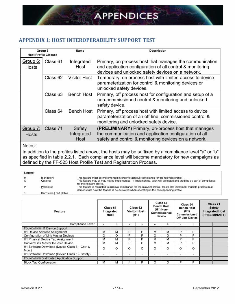
Revision 3.2.1 - 114 - September 2012
APPENDIX 1: HOST INTEROPERABILITY SUPPORT TEST
Group 6 Name Description Host Profile Classes
Class 61 Integrated Primary, on process host that manages the communication Host and application configuration of all control & monitoring
devices and unlocked safety devices on a network. Class 62 Visitor Host Temporary, on process host with limited access to device
parameterization for control & monitoring devices or unlocked safety devices.
Class 63 Bench Host Primary, off process host for configuration and setup of a non-commissioned control & monitoring and unlocked safety device.
Group 6: Hosts
Class 64 Bench Host Primary, off process host with limited access to device parameterization of an off-line, commissioned control & monitoring and unlocked safety device.
Group 7: Hosts
Class 71 Safety (PRELIMINARY) Primary, on-process host that manages Integrated the communication and application configuration of all
Host safety and control & monitoring devices on a network. Notes: In addition to the profiles listed above, the hosts may be suffixed by a compliance level "a" or "b" as specified in table 2.2.1. Each compliance level will become mandatory for new campaigns as defined by the FF-525 Host Profile Test and Registration Process.
Legend
M
Mandatory
This feature must be implemented in order to achieve compliance for the relevant profile. O Optional This feature may or may not be implemented. If implemented, such will be tested and credited as part of compliance
for the relevant profile. P Prohibited This feature is restricted to achieve compliance for the relevant profile. Hosts that implement multiple profiles must
demonstrate how the feature is de-activated when operating in the corresponding profile. ‘-’ Don’t care | N/A | DNA
Feature
Class 61
Integrated Host
Class 62
Visitor Host (H1)
Class 63 Bench Host (H1) Non-
Commissioned Device
Class 64
Bench Host (H1)
Commissioned Off-Line Device
Class 71 Safety
Integrated Host (PRELIMINARY)
Compliance Level: a b a b a b a b FOUNDATION H1 Device Support H1 Device Address Assignment M M P P M M P P Configuration of Link Master Devices O O P P O O P P H1 Physical Device Tag Assignment M M P P M M P P Convert Link Master to Basic Device M M P P M M P P H1 Software Download (Device Class 3 – Cntrl & Mon.) O O O O O O O O
H1 Software Download (Device Class 5 – Safety) - - - - - - - - FOUNDATION Distributed Application Support Block Tag Configuration M M P P O O P P
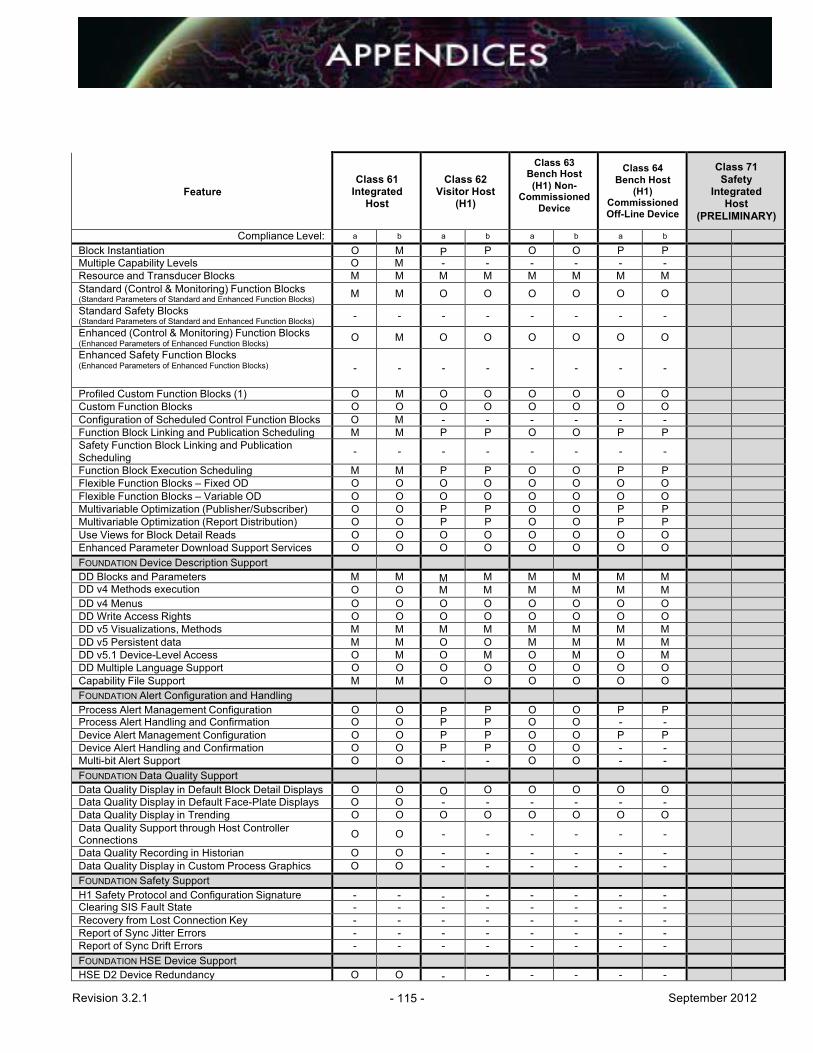
Revision 3.2.1 - 115 - September 2012
Feature
Class 61
Integrated Host
Class 62
Visitor Host (H1)
Class 63 Bench Host (H1) Non-
Commissioned Device
Class 64
Bench Host (H1)
Commissioned Off-Line Device
Class 71 Safety
Integrated Host
(PRELIMINARY)
Compliance Level: a b a b a b a b Block Instantiation O M P P O O P P Multiple Capability Levels O M - - - - - - Resource and Transducer Blocks M M M M M M M M Standard (Control & Monitoring) Function Blocks (Standard Parameters of Standard and Enhanced Function Blocks) M M O O O O O O Standard Safety Blocks (Standard Parameters of Standard and Enhanced Function Blocks) - - - - - - - - Enhanced (Control & Monitoring) Function Blocks (Enhanced Parameters of Enhanced Function Blocks)
O M O O O O O O Enhanced Safety Function Blocks (Enhanced Parameters of Enhanced Function Blocks)
-
-
-
-
-
-
-
-
Profiled Custom Function Blocks (1) O M O O O O O O Custom Function Blocks O O O O O O O O Configuration of Scheduled Control Function Blocks O M - - - - - - Function Block Linking and Publication Scheduling M M P P O O P P Safety Function Block Linking and Publication Scheduling - - - - - - - -
Function Block Execution Scheduling M M P P O O P P Flexible Function Blocks – Fixed OD O O O O O O O O Flexible Function Blocks – Variable OD O O O O O O O O Multivariable Optimization (Publisher/Subscriber) O O P P O O P P Multivariable Optimization (Report Distribution) O O P P O O P P Use Views for Block Detail Reads O O O O O O O O Enhanced Parameter Download Support Services O O O O O O O O FOUNDATION Device Description Support DD Blocks and Parameters M M M M M M M M DD v4 Methods execution O O M M M M M M DD v4 Menus O O O O O O O O DD Write Access Rights O O O O O O O O DD v5 Visualizations, Methods M M M M M M M M DD v5 Persistent data M M O O M M M M DD v5.1 Device-Level Access O M O M O M O M DD Multiple Language Support O O O O O O O O Capability File Support M M O O O O O O FOUNDATION Alert Configuration and Handling Process Alert Management Configuration O O P P O O P P Process Alert Handling and Confirmation O O P P O O - - Device Alert Management Configuration O O P P O O P P Device Alert Handling and Confirmation O O P P O O - - Multi-bit Alert Support O O - - O O - - FOUNDATION Data Quality Support Data Quality Display in Default Block Detail Displays O O O O O O O O Data Quality Display in Default Face-Plate Displays O O - - - - - - Data Quality Display in Trending O O O O O O O O Data Quality Support through Host Controller Connections O O - - - - - - Data Quality Recording in Historian O O - - - - - - Data Quality Display in Custom Process Graphics O O - - - - - - FOUNDATION Safety Support H1 Safety Protocol and Configuration Signature - - - - - - - - Clearing SIS Fault State - - - - - - - - Recovery from Lost Connection Key - - - - - - - - Report of Sync Jitter Errors - - - - - - - - Report of Sync Drift Errors - - - - - - - - FOUNDATION HSE Device Support HSE D2 Device Redundancy O O - - - - - -

Revision 3.2.1 - 116 - September 2012
Feature
Class 61
Integrated Host
Class 62
Visitor Host (H1)
Class 63 Bench Host (H1) Non-
Commissioned Device
Class 64
Bench Host (H1)
Commissioned Off-Line Device
Class 71 Safety
Integrated Host
(PRELIMINARY)
Compliance Level: a b a b a b a b HSE D3 Device Redundancy O O - - - - - - HSE Interface Redundancy O O - - - - - - HSE LD Support: Block Parameter Access O O - - - - - - HSE LD Support: Report Re-Distribution O O - - - - - - HSE LD Support: Republishing O O - - - - - - HSE Software Download (Device Class 4 - HSE) O O O O O O O O

Revision 3.2.1 - 117 - September 2012
APPENDIX 2: CABLE CHARACTERISTICS
A2.1 General The cable shall comply with the following requirements:
A2.1.1 UL Listing The cable shall comply to one or more of the following ratings:
• Instrument Tray Cable (ITC) • Power Limited Tray Cable (PLTC) • Tray Cable (TC) • Metal Clad Cable (MC or MC-HL)
A2.1.2 Temperature Range The cable shall have a -30 to +90 ºC minimum operating temperature range.
A2.1.3 Optional Characteristics Optional ratings and characteristics shall be indicated by the manufacturer as applicable:
• Exposed Run (ER) • Armored • Direct burial • Marine shipboard • Oil resistant • Abrasion resistant • Weld flash resistant • Cutting fluid resistant • Jacket color (generally orange, but may be blue for intrinsically safe area use, etc.) • Wire colors (generally brown for positive and blue for negative) • Capacitance and inductance per km (for FISCO use) • Overall cable roundness (as a consideration for gland sealing)
A2.2 Characteristic Impedance, Z0 The characteristic impedance of each twisted pair in a cable shall be 100 +/- 20 Ohms. The characteristic impedance shall be determined by any one of the methods described in ASTM D4566-05 or equivalent international standard at 31.25 kHz.
A2.3 Attenuation
The signal attenuation of each twisted pair in the cable shall be maximum 3.0 dB/km at 39 kHz.
A2.4 Wire The minimum trunk wire-pair size shall have a maximum resistance of 23.5 Ohms/km at 20 °C (18 AWG) per conductor. The minimum spur wire-pair size shall have a maximum resistance of 59.4 Ohms/km at 20 °C (22 AWG) per conductor. Wires shall be annealed copper, tin coated.
Revision 3.2.1 - 118 - September 2012
A2.5 Shield Construction Requirements Each twisted pair shall be individually shielded. The shield shall be metalized polyester tape. A drain wire shall have a resistance less than 51 Ohms/km. If another shield construction method is used, the manufacturer shall provide assurance that the alternate method is functionally equivalent to the metalized polyester shield. In a multi-pair cable, each pair is individually shielded with an overall shield and all shields are isolated from each other.
A2.6 Wire-to-Shield Capacitance Unbalance The difference in capacitance between one wire (+) and the shield and the other wire (-) and the shield shall be no more than 4 pF/meter average. A minimum of 30 m cable length shall be used to test this parameter.
A2.7 Wire Twists Per Meter There shall be 10 to 22 wire twists per meter for single or multi-pair cables.
A2.8 Minimum Bend Radius The minimum bend radius of the cable shall be specified. This must consider the specified cable temperature range and the possible loss of shield coverage due to bending.
A2.9 Jacket Resistance The minimum resistance between the cable’s shield and the metal structure the cable may be in or on, when a steady voltage of 500 Vdc is applied for one minute, shall be 1 MOhm/330 meters.
Revision 3.2.1 - 119 - September 2012
APPENDIX 3: RISK MANAGEMENT The following valve process effect rating and network/segment loading method should be used as a guide and modified to suit the individual process facility. The valve and associated measurement process effect shall be defined for prudent loading of fieldbus segments. The following ratings should be assigned to each valve and segment. Commentary: The design restrictions are intended to minimize the effect of human error and interoperability problems from affecting plant reliability. The intent of High Process Effect designs is to keep the number and variety of devices on a network small so that a minimum of interaction is required with the segment. Less is better, however, a unit with large numbers of dependent service valves may decide to increase the maximum number of valves to three (3) for High Process Effect. Instruments that are part of a common reliability concept should not be on the same network (share the same Host I/O controller) and, if possible, backplane to minimize the number of possible common mode failure points.
A3.1 Process Effect Ranking HIGH Criteria • Causes a system trip, which shuts down entire operating process or train or no
production for more than one (1) 8-hour shift. • And no operator action and time available to mitigate process (entire) or train shutdown.
A3.2 Process Effect Ranking MEDIUM Criteria • Causes a system trip, which shuts down entire operating process or train but production
can be resumed on the same 8-hour shift. • Or production will be reduced to lower rates. • In this case, the process dynamics will allow the operator enough time to mitigate the
problem. Final control element can be operated manually and can be back online shortly without process shutdown.
A3.3 Process Effect Ranking LOW Criteria • Will not cause short-term risk of a system trip and will not shutdown the entire operating
process or train. • Final control element can be in a fail position for a short time without immediate operator
action.

Revision 3.2.1 - 120 - September 2012
FAILURE MITIGATIONS
LEVEL 1 LEVEL 2 LEVEL 3 LEVEL 4
PROCESS EFFECT CATEGORY ▼
NO OPERATOR ACTION OR
TIME AVAILABLE TO MITIGATE UNIT
OR TRAIN SHUTDOWN
WHEN CONTROL LOOP
FAILS
LIMITED OPERATOR
ACTION AND IMMEDIATE TIME
TO MITIGATE UNIT OR TRAIN
SHUTDOWN WHEN
CONTROL LOOP FAILS
AVAILABLE OPERATOR
ACTIONS AND LIMITED TIME TO MITIGATE
UNIT OR TRAIN SHUTDOWN
WHEN CONTROL LOOP
FAILS
AVAILABLE OPERATOR
ACTIONS AND EXTENDED TIME
TO MITIGATE UNIT OR TRAIN
SHUTDOWN WHEN CONTROL
LOOP FAILS
1. UNIT or TRAIN SHUTDOWN No production for more than one (1)8-hour shift.
HIGH MEDIUM MEDIUM LOW
2. UNIT or TRAIN CONTINUES TO OPERATE Production can be resumed on the same shift.
MEDIUM MEDIUM LOW LOW
3. UNIT or TRAIN CONTINUES TO OPERATE Production will be reduced to lower rates.
MEDIUM LOW LOW LOW
4. UNIT or TRAIN CONTINUES TO OPERATE Insignificant impact to production or quality.
LOW LOW LOW LOW

Revision 3.2.1 - 121 - September 2012
Table A3.1 Process Effect Ranking Matrix

Revision 3.2.1 - 122 - September 2012
Risk Management Selections
Redundant Controller Required
Redundant H1 Interface Optional
Redundant Power Supplies Required
DC Power Supply Battery Capacity Required - 30 minutes minimum
Redundant Power Conditioners (Fieldbus Power Supplies) Required
Field Backup LAS Only if a redundant H1 interface is not provided and high reliability is necessary
Control in Valve Positioner Preferred for simple loops
Control in Transmitter Only for Cascade Primary
Control in Host Required for Complex Loops
Valve/Segment Process Effect Ranking Required
Maximum Devices per Segment 12 (default unless otherwise noted in section 7.4 or 7.7)
Maximum Control Valves per Segment 3 (default unless otherwise noted in section 7.4 or 7.7)
Repeaters Requires Project Lead Engineer approval
Table A3.2 Network/Segment Risk Management Selections

Revision 3.2.1 - 123 - September 2012
APPENDIX 4: FIELDBUS SEGMENT TESTING
A4.1 Fieldbus Segment Commissioning Form
Table A5.1. FOUNDATION fieldbus segment commissioning form for non-isolated coupler or trunks only. On segments with isolated couplers, the test must be repeated for each spur.
Company: Location: Unit: Segment No.: Date Step 1: This testing is performed before the segment is plugged into the power conditioner. (+) to (-) Expected > 50K ohm Actual = (+) to shield Expected > 20M ohm Actual = (-) to shield Expected > 20M ohm Actual = (+) to ground Expected > 20M ohm Actual = (-) to ground Expected > 20M ohm Actual = shield to ground Expected > 20M ohm Actual =
Step 2: Plug the segment into the power conditioner. Shield to ground Expected < 1 ohm Actual =
Step 3: Clip a FBT-6 or P&F tester onto the segment and capture the segment diagnostics file. Segment Diagnostics File: Date:
Technician:
Step 4: Optionally capture a segment trace file with an oscilloscope.
Segment Trace File: Date:
Technician:

Revision 3.2.1 - 124 - September 2012
A4.2 Sample Waveforms Measure the AC waveform at the marshaling cabinet terminal block field connector.
Procedure Expected Result Set the scope to AC, 200 mV/division 700 mV and 900 mV peak to peak nominal
10 microseconds/division for best results and press HOLD to capture the waveform.
Verify the waveform against the expected waveform shown in Waveform with Two Terminators and 1,000 ft. Cable (Figure A5.1). Note the differences in the signals with one terminator (Waveform with One Terminator and 1,000 ft. Cable) and with three terminators (Waveform with Three Terminators and 1,000 ft. Cable). Right around 700 is the design normal, if you have everything per design it will come out around 700. If you are as high as 1100 there is something wrong, perhaps you are missing a terminator or something is causing a higher than normal impedance. Down around 500 or so, you may be experiencing normal signal loss from the other end of the segment. If you start getting below 500, however, you could start dropping packets. The following figure (A4.1) shows a waveform with two terminators and 1,000 ft. of cable. This is the expected waveform.
Figure A4.1 Waveform with Two Terminators and 1,000 ft. Cable.
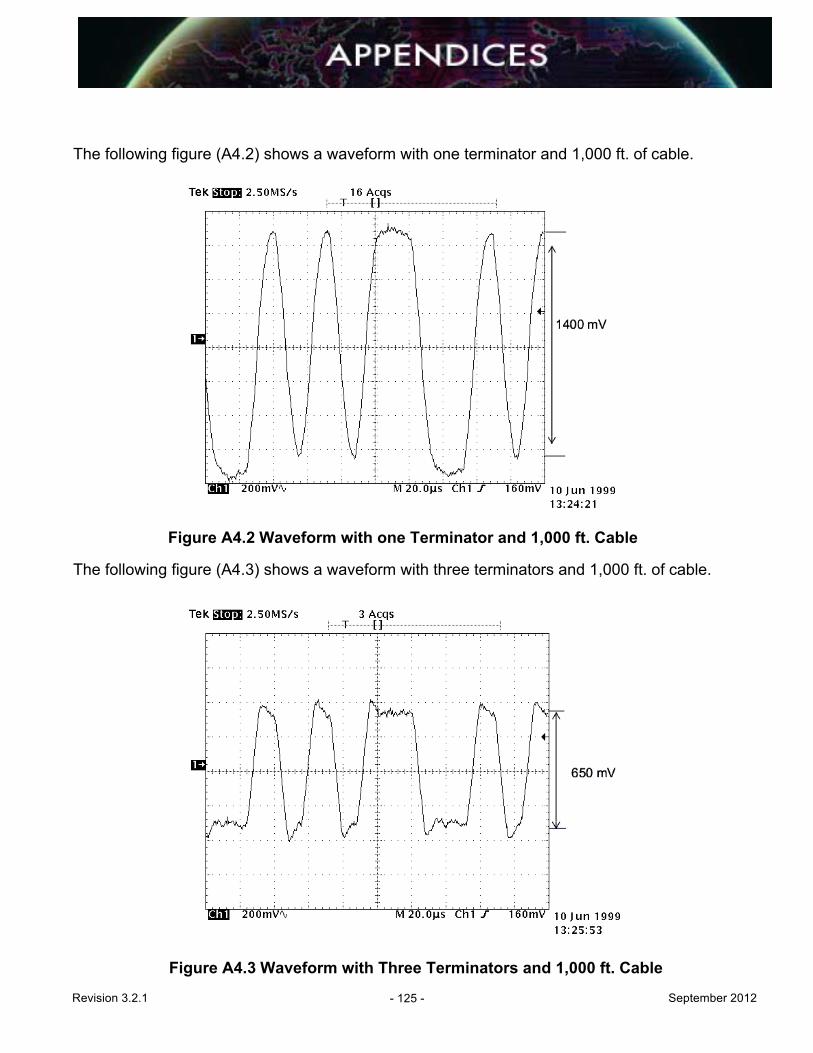
Revision 3.2.1 - 125 - September 2012
The following figure (A4.2) shows a waveform with one terminator and 1,000 ft. of cable.
Figure A4.2 Waveform with one Terminator and 1,000 ft. Cable The following figure (A4.3) shows a waveform with three terminators and 1,000 ft. of cable.
Figure A4.3 Waveform with Three Terminators and 1,000 ft. Cable

Revision 3.2.1 - 126 - September 2012
APPENDIX 5: FOUNDATION FIELDBUS SEGMENT AND LOOP DRAWINGS Four drawings are provided illustrating both FOUNDATION fieldbus segment drawings and instrument loop drawings using two different technologies. The first two drawings are based upon “brick” style field connectors and assume a significant distance between the device couplers. This layout should not be used for device couplers inside the same junction box. In that case, the trunk line will be connected directly to the individual device couplers. A segment drawing (Figure A5.1) illustrates how all the devices on one segment are connected back to the H1 interface on the Host system. Figure A5.1 shows six (6) FOUNDATION fieldbus devices that are connected onto one H1 segment. An instrument loop drawing (Figure A5.2) illustrates all the devices associated with the implementation of one control loop. In this case, the control loop comprises a fieldbus transmitter (flow) and a 4-20 mA level transmitter connected to a 4-20 mA control valve. In this instance, the loop drawing combines both current (4-20 mA) and digital (FOUNDATION fieldbus) technologies onto one drawing. The third drawing (Figure A5.3) is another example of a segment drawing using terminal blocks in the field junction box (versus a "brick" style connector). In this segment drawing, four (4) FOUNDATION field devices are connected onto one segment. The fourth drawing (Figure A5.4) is another example of an instrument loop drawing. This time, the level transmitter and the level control valve are implemented via FOUNDATION fieldbus, whereas the flow transmitter is implemented via 4-20 mA. Again, terminal blocks are used in the H1 segment implementation consistent with the associated segment drawing (Figure A5.3). All drawings are output from SmartPlant Instrumentation (SPI) (previously known as INtools) using the Enhanced SmartLoop (ESL) functionality of the wiring module. Project specific drawings may be slightly different, depending on specific project decisions on the representation of field devices, terminal blocks, wiring colors and field junction boxes. However, the basic layout will be similar, given the ESL output limits.

Revision 3.2.1 - 127 - September 2012
Figure A5.1 Segment Drawing Based on Connectors
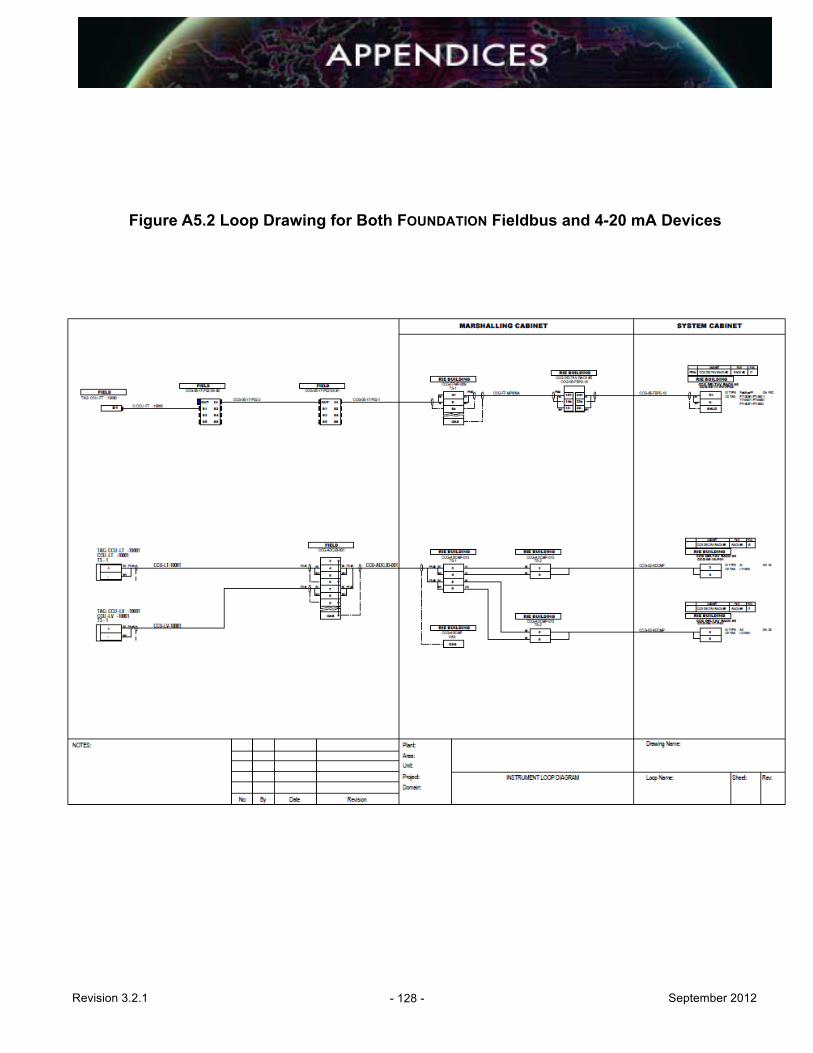
Revision 3.2.1 - 128 - September 2012
Figure A5.2 Loop Drawing for Both FOUNDATION Fieldbus and 4-20 mA Devices

Revision 3.2.1 - 129 - September 2012
Figure A5.3 Segment Drawing Applying Device Couplers in a JB
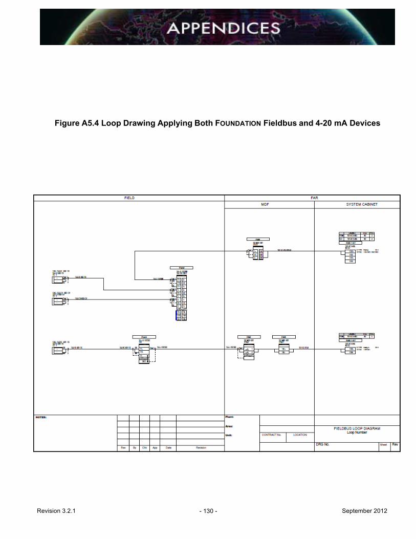
Revision 3.2.1 - 130 - September 2012
Figure A5.4 Loop Drawing Applying Both FOUNDATION Fieldbus and 4-20 mA Devices

Revision 3.2.1 - 131 - September 2012
APPENDIX 6: MAINTENANCE GRAPHICS The following screens may be used as examples of maintenance documentation and navigation for FOUNDATION fieldbus segments. These are custom, user-built graphics that can show the status of multiple fieldbus segments in a plant unit. Pop-up screens can show individual segments. The purpose of these screens is to reduce the number of mouse clicks required to navigate through diagnostic displays from typical explorer trees while giving additional information about device criticality and alert status (live data). Figure A6.1 shows a typical maintenance screen shot for a process unit. The colors used are in compliance with the NAMUR 107 standard. All project FOUNDATION fieldbus maintenance displays shall be NAMUR 107 compliant in the display of alert priority. The device vendor shall provide details of device maintenance and indicate the impact of device changes on other devices and/or Host system with regard to monitoring, historian database, advanced diagnostics, calibrating and configuring, including a “help” guide.

Revision 3.2.1 - 132 - September 2012
Figure A6.1 FOUNDATION Fieldbus Example of NAMUR NE 107 Maintenance Graphics

Revision 3.2.1 - 133 - September 2012
APPENDIX 7: ACCEPTANCE TESTING PROCEDURES
A7.1 Introduction The use of FOUNDATION fieldbus will necessitate some different or modified acceptance testing criteria and procedures. The following is meant to be a guideline only. The use of specific Host systems and field devices and wiring components will require modified and/or additional procedures.
A7.2 Device Integration Testing A complete functional test shall be conducted for each type of fieldbus device used in the project (i.e., third-party products).
A7.2.1 Functionality Test Procedure This test will include, but is not limited to, plug-and-play interconnectivity to the Host system, verifying access to all Function Blocks being used in the project, actual device operation, (e.g. stroke valves/MOVs, simulate process inputs for transmitters, etc.).
A7.2.2 Device Check For each device to be tested, complete at least the following steps:
• Document the hardware and DD revisions of the device. Verify that corresponding DD files are included in the Host system library. If not existing, contact the Host manufacturer and determine the availability and add it to the library. Some Host systems modify the files somewhat in order to ensure compatibility with their system. Otherwise, the DDs may be obtained from the device manufacturer or from the Fieldbus Foundation website.
• If the particular device (and revision) has been tested by the Host system vendor, obtain the testing results (if possible) and check for any known problems and work-arounds. Use that information to create or supplement device testing procedures.
• Check that the database for this device is correctly populated (either by test criteria or specific project criteria). It is assumed that the database is populated by an upload followed by modifying the relevant ranges, alarms, units, etc. The correct database population is checked by comparison with the relevant documents and the physical device itself.
• Perform a download to the FOUNDATION fieldbus device and observe that no unexplained errors occur. Host systems will report download errors. This should include verification that all RBs and TBs can be place Out of Service (OOS) and returned to Automatic (Auto) correctly.
• Observe and record the Link Master capabilities of the device. If it is Link Master capable, ensure that the capability can be toggled off or on as the project requires.
• Observe and record the parameter default values as received from the factory. These values are usually available from the device manufacturer’s operation and
Revision 3.2.1 - 134 - September 2012
maintenance manuals, the defaults should be physically compared to the device as occasionally changes are made to the devices and not updated in the manuals in a timely manner. A determination can then be made as to which, if any, of the default values must be made to suit the project needs.
• Perform a calibration and setup for each type of FOUNDATION fieldbus device, using inherent device methods, or dedicated EDDL or FDT/DTM wizards depending on the Host system and available asset management tools. All calibration and setup procedures for each device shall be documented in detail and approved by the end user. The test shall include a calibration and setup for each type of device. Examples include (but are not limited to) the following:
Temperature Transmitters: • Changing RTD/thermocouple types and downloading transmitter span pressure
transmitters
Pressure Transmitters • Zeroing pressure and DP transmitters • Zeroing elevation on DP level transmitters
Valve Positioners: • Setup and calibration of a new positioner on a control valve
• Create a diagnostic alert or alarm condition and observe the annunciation in the HMI.
While that alert or alarm is still active, create another separate alert or alarm condition and observe if that condition is also annunciated.
• For valves and other final elements, observe and record fault state actions available within the device and simulate as many fault conditions as possible to emulate communications loss or diagnostic alarm conditions.
Commentary: The purpose of these requirements is to verify and document the standard default condition of the device, the ease of access to calibration wizards and setup procedures via the Host or maintenance system as well as how the device will react to potential conditions.
A7.3 Factory Acceptance Testing (FAT) Develop and document procedures for the following:
A7.3.1 H1 Interface or Linking Device Operation Using a test segment (with the types of wiring components and at least one field device to be used on the project), connect the segment to every port on the H1 interface or linking devices (including spares) at the terminal block designated for the field wiring or system cable downstream of the fieldbus power supply. Observe that the device(s) is recognized on the Host system live list.
Revision 3.2.1 - 135 - September 2012
If power supplies or power conditioners with switchable terminators are used, verify that the terminator switch is in the correct position. Verify that the DC voltage and LAS signal is within rated limits of the power supply. Commentary: Verification of DC voltage and LAS signal may be accomplished with hand-held test equipment, a portable oscilloscope, or with advanced diagnostic modules (online or offline).
A7.3.2 Redundancy Switch-over Test Procedure Where redundant FOUNDATION fieldbus interface cards and/or power supplies are used, the redundant operation of each component shall be tested. The test shall verify that automatic fail over shall not cause an upset (i.e., signal bumps, loss of operator view, mode changes, etc.). All FOUNDATION fieldbus interface cards and power supplies shall be tested. All failure alarms shall be tested and signed off.
A7.3.3 Field Device Operation If separate Device Integration Testing is not performed prior to FAT, then use the procedures described in Device Integration (Section A8.2) above.
A7.3.4 Data Reconciliation For each configured parameter residing in the FOUNDATION fieldbus devices (e.g. in TB, AI, PID or AO block), complete the following steps:
• Verify the appropriate scale and engineering units are configured as needed in both the AI (AO) Function Block and in the Transducer Block.
• Verify that the scale and engineering units are correct and consistent for the • FOUNDATION fieldbus device and the associated faceplate, graphics and trends. • Verify that all engineering units in the Transducer Block are consistent with the project
standards. In particular, engineering units used for diagnostic and not for graphics may be overlooked and require extensive rework if not detected at the device integration test.
• Simulate a process variable equal to half the scale and verify. • The process variable appears correctly within the PV parameter field of the AI (AO)
block. • The same value appears where the PV parameter is configured on a process graphic. • The same value appears where the PV parameter is configured on a (historical) trend.
For the same device, generate a PV (if more than one is used, check every parameter separately) that exceeds the applied alarm limits and verify that the pre-configured alarms appear at the operator and/or maintenance workstation.
If the device is a valve positioner, complete the following steps:
• Verify that the AO block is in CAS mode.
Revision 3.2.1 - 136 - September 2012
• Verify that the PID block is in MAN mode. • Manually enter the controller output on the controller faceplate. • Verify the valve positioner maintains the same output.
A7.3.5 Verification of Control Strategies and Monitoring Verification of control strategies and monitoring applications using FOUNDATION fieldbus devices can be difficult during a normal FAT, since it is not practical to provide all necessary field devices (especially if control in the field or other specialized Function Blocks are used). They can be accomplished with simulation software (if available from the Host system manufacturer) or simple monitoring loops can be verified using more simple methods as described in Data Reconciliation (Section A8.3.4) above. Specific procedures should be developed and documented by the Host system manufacturer. A selection of segments shall be tested which will cover all device types, the heaviest loaded segments, and a representative selection of typicals. The selected segments shall be tested in accordance with the segment check procedure (Section A8.5.1) below.
A7.3.5.1 Transfer of Data to HMI or Historian
As with control strategies and monitoring applications, verification can be difficult. Simulation applications (if available from the Host system manufacturer) may be used or the simple methods described in Data Reconciliation (Section A8.3.4) above, such as placing an AI block in manual and typing in a value. Specific procedures should be developed and documented by the Host system manufacturer.
A7.4 Site Acceptance Testing Requirements Unless specifically warranted, a full re-test of the FAT is not necessarily required. A representative sample of components should be chosen to repeat some of the testing from FAT. An example would be to test only one port on each H1 interface or linking device in order to ensure that the system had been properly reassembled.
A7.5 Segment Testing/Commissioning Procedure Each segment, including spares, shall be operationally tested by live connection of at least one but preferably all devices. The device shall be connected to the terminal block designated for the field wiring or system cable downstream of the fieldbus power- conditioning module (FPPS).
A7.5.1 Segment Check For each selected FOUNDATION fieldbus segment to be tested, complete the following steps:
• Complete segment testing and commissioning. • Test/confirm that the Host system and devices have the same firmware/software
revisions.

Revision 3.2.1 - 137 - September 2012
• Test/confirm that all H1 interface cards used in the Host system are the same firmware/software revision.
• Check that the relevant segment communication parameters are correct and that the macrocycle duration has been set for each network.
• Check that the power-conditioning module (generally an FPPS) operates correctly and that a failure is communicated to the Host system.
• Check that the network/segment recovers from a short circuit. • Measure the overall current consumption. • Check that the FOUNDATION fieldbus Host system interface module operates correctly
and that a failure is identified by the Host system. • Check that the Back-up LAS is functioning and is executing the correct schedule. • This only applies if Back-up LAS will be applied (i.e., for segments with CIF); in all
other cases, no Back-up LAS (BLAS) is required and this test can be omitted. • Monitor stable operation for at least 12 hours.
Optional:
• Check the communication load under stable (no download) condition. A load of less than 70% will be required. The Host system might supply this information.
• Ensure sufficient spare capacity is provided by connecting two extra fieldbus devices and observing proper operation of the full segment.
Commentary: Some of the segment check may have previously been tested (such as verification of the operation of H1 interfaces), and therefore may be omitted by the user.