components for material handling and process plants · components for material handling and process...
TRANSCRIPT

We know how
www.claudiuspeters.com
Components for material handlingand process plants
3
www.claudiuspeters.com
Flow Control Gate
The Claudius Peters Flow Control Gate is used wherever bulksolids have to be discharged from silos and bins, in ametered and controlled manner.
Especially in the cement and building materials industryClaudius Peters Flow Control Gates have been usedsuccessfully for many years for various applications as shut-off or dosing aggregate.
The Claudius Peters Flow Control Gate in standard designcan be supplied with pneumatic actuator drive, servo-motoror as maintenance device with hand lever. The ClaudiusPeters Flow Control Gate program comprises variousfunctions. Simple open/close functions under silos,positioning functions for material loading processes up tohigh-precision metering processes at weighing systems canbe realized optimally by use of the Claudius Peters FlowControl Gates.
682.
0093
.002
1A/0
0.en
2
Advantages of a Claudius Peters Flow Control Gate
● Even and controlled material discharge out of silos
● Pneumatically controlled gates suitable for highdynamical process operations with high accuracy(e.g. belt weigher, flow meter)
● The compact modular design with exchangeablecassette-type sealing ensures easy maintenance atlow maintenance costs
● Different designs of cutouts for optimal throughput& function
● Additional handwheel and a local control switch onthe motor actuator drive for manual or electricaloperation direct at machinery
● Flow control gates ready prepared for Profibus
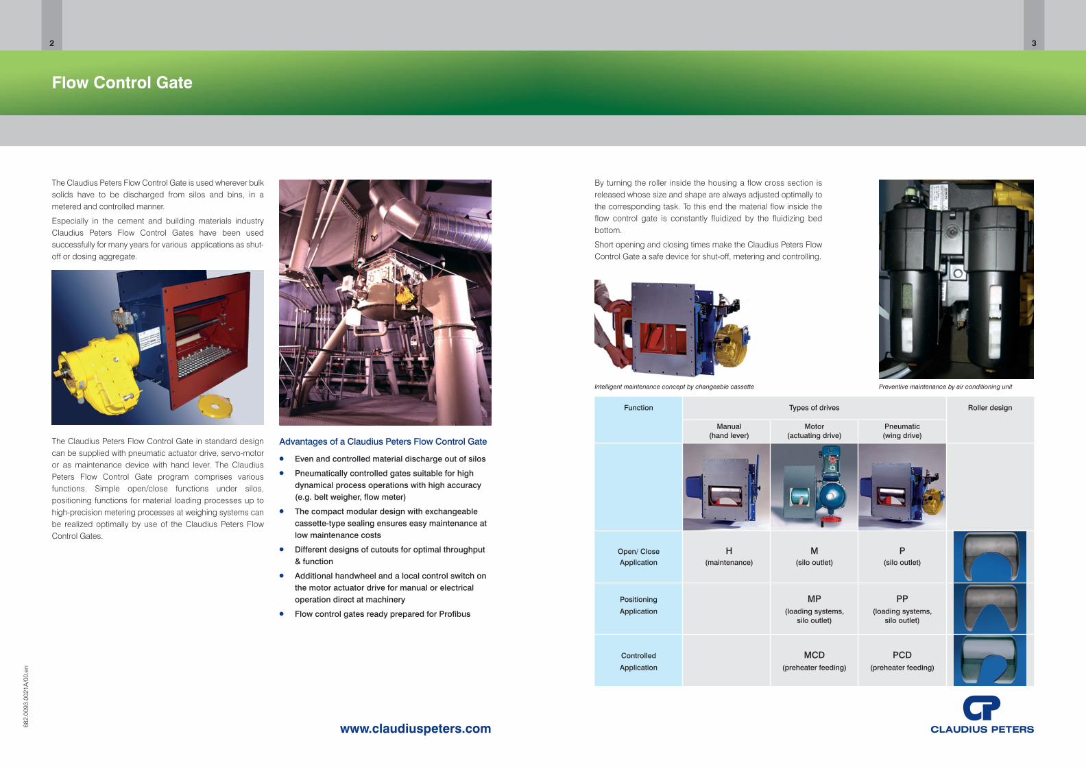
By turning the roller inside the housing a flow cross section isreleased whose size and shape are always adjusted optimally tothe corresponding task. To this end the material flow inside theflow control gate is constantly fluidized by the fluidizing bedbottom.
Short opening and closing times make the Claudius Peters FlowControl Gate a safe device for shut-off, metering and controlling.
Intelligent maintenance concept by changeable cassette Preventive maintenance by air conditioning unit
Function Types of drives Roller design
Manual Motor Pneumatic(hand lever) (actuating drive) (wing drive)
Open/ Close H M PApplication (maintenance) (silo outlet) (silo outlet)
Positioning MP PPApplication (loading systems, (loading systems,
silo outlet) silo outlet)
Controlled MCD PCDApplication (preheater feeding) (preheater feeding)
By turning the roller inside the housing a flow cross section isreleased whose size and shape is always adjusted optimallyto the corresponding task. To this end the material flow insidethe flow control gate is constantly fluidized by the fluidizingbed bottom.
Short opening and closing times make the Claudius PetersFlow Control Gate a safe device for shut-off, metering andcontrolling
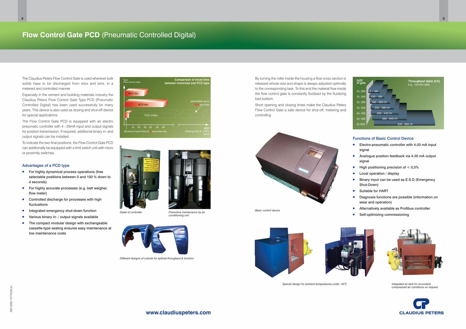
Basic control device
Integrated air tank for inconstantcompressed air conditions on request
Special design for ambient temperatures under -40°C
Functions of Basic Control Device ● Electro-pneumatic controller with 4-20 mA input
signal
● Analogue position feedback via 4-20 mA outputsignal
● High positioning precision of < 0,5%
● Local operation / display
● Binary input can be used as E.S.D (EmergencyShut-Down)
● Suitable for HART
● Diagnosis functions are possible (information onwear and operation)
● Alternatively available as Profibus controller
● Self-optimizing commissioning
Flow Control Gate PCD (Pneumatic Controlled Digital)
The Claudius Peters Flow Control Gate is used wherever bulksolids have to be discharged from silos and bins, in ametered and controlled manner.
Especially in the cement and building materials industry theClaudius Peters Flow Control Gate Type PCD (PneumaticControlled Digital) has been used successfully for manyyears. This device is also used as dosing and shut-off devicefor special applications.
The Flow Control Gate PCD is equipped with an electropneumatic controller with 4 - 20mA input and output signalsfor position transmission. If required, additional binary in- andoutput signals can be installed.
To indicate the two final positions, the Flow Control Gate PCDcan additionally be equipped with a limit switch unit with microor proximity switches.
Advantages of a PCD type ● For highly dynamical process operations (free
selectable positions between 0 and 100 % down to4 seconds)
● For highly accurate processes (e.g. belt weigher,flow meter)
● Controlled discharge for processes with highfluctuations
● Integrated emergency shut-down function
● Various binary in- / output signals available
● The compact modular design with exchangeablecassette-type sealing ensures easy maintenance atlow maintenance costs
Preventive maintenance by airconditioning unit
Detail of controller
Different designs of cutouts for optimal throughput & function
682.
0093
.107
7A/0
0.en
4
www.claudiuspeters.com
5
76
www.claudiuspeters.com682.
0093
.002
2A/0
0.en
Flow Control Gates V (Vertical)
The Claudius Peters Flow Control Gate is used wherever bulksolids have to be discharged from silos and bins, in ametered and controlled manner.
This type of flow control gate has been designed especiallyfor all those applications where the space under the silo islimited and a classic side discharge cannot be used. TheClaudius Peters Flow Control Gates Type V have been usedfor various applications as shut-off aggregate with simpledosing functions.
Special solution for VERTICAL throughput● For dosing function with intermediate positions
● For installation under silos
● 100% tight sealing system
● Changeable sealing cassette for easy maintenance
● Available in sizes 200 x 200mm and 400 x 400mm
Solenoid valves for intermediate positioningRoller design with cutout
Preventive maintenance by optional airconditioning unit
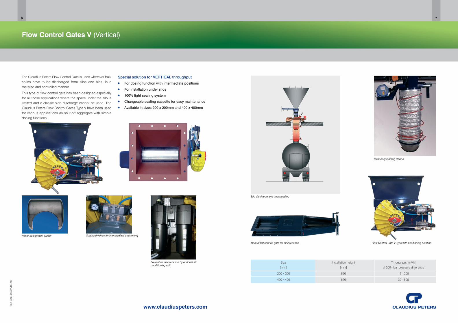
Silo discharge and truck loading
Stationary loading device
Size Installation height Throughput [m³/h]
[mm] [mm] at 300mbar pressure difference
200 x 200 520 15 - 200
400 x 400 520 30 - 500
Flow Control Gate V Type with positioning functionManual flat shut off gate for maintenance
www.claudiuspeters.com
FLUIDCON
Pneumatic conveying has always been an acceptable meansfor transporting fine materials from one location to the other.
From a positive point of view, the initial investment andmaintenance costs are typically lower when compared tomechanical conveying systems.
However, the energy consumption for the air supply onconventional pneumatic systems is considerably higher thanother options power requirements.
The Claudius Peters FLUIDCON system utilizes theadvantages of typical pneumatic conveying at considerablylower energy requirements.
FLUIDCON has the benefits of less power consumption dueto the incorporation of the aeroslide transportation principlewithin the transport pipe.
Additionally, it provides a dense phase system with increasedbulk material load. Depending on the transport pipe routing,the new Claudius Peters FLUIDCON system can substantiallyreduce power consumption. FLUIDCON system can be usedto convey all fine bulk solids which can be fluidized with lowair velocities, and expands homogeneously during theprocess. Advantages of Claudius Peters FLUIDCON Systems
● Reduced operating costs - substantially less energyconsumption compared to conventional pneumaticconveying
● High availability - the system is easily started orrestarted even when solids remain in the conveyingline
● Gentle material handling - this is due to lowerconveying velocities starting at approximately2-3 m/s and ending at approximately 5 -10 m/s
● Alternative feed systems - with a reduction in theconveying pressure, Claudius Peters X-Pumps(screw pumps) can be installed instead ofconventional pressure vessels to insure savings inheight and capital costs
682.
0093
.002
2A/0
0.en
8
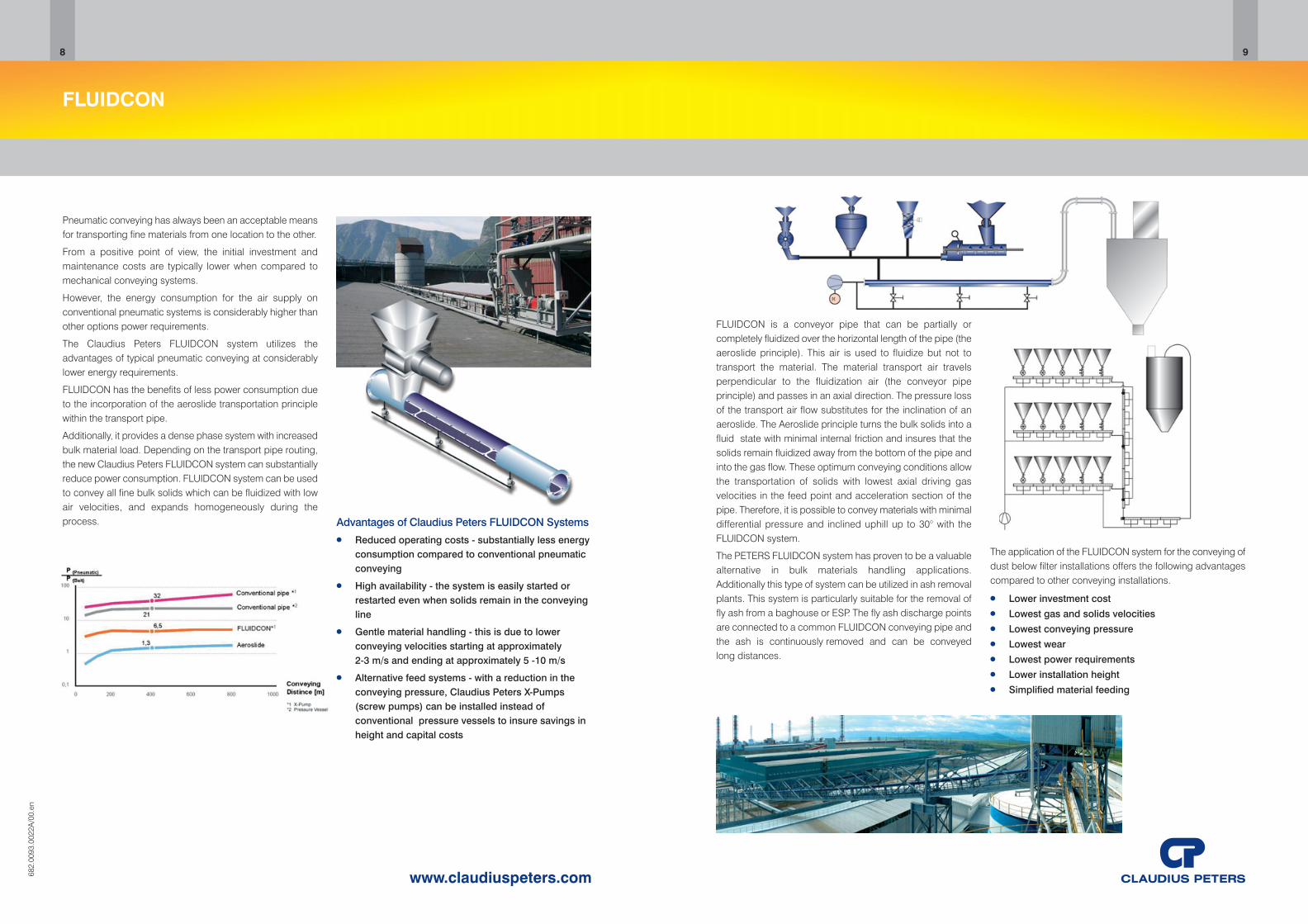
FLUIDCON is a conveyor pipe that can be partially orcompletely fluidized over the horizontal length of the pipe (theaeroslide principle). This air is used to fluidize but not totransport the material. The material transport air travelsperpendicular to the fluidization air (the conveyor pipeprinciple) and passes in an axial direction. The pressure lossof the transport air flow substitutes for the inclination of anaeroslide. The Aeroslide principle turns the bulk solids into afluid state with minimal internal friction and insures that thesolids remain fluidized away from the bottom of the pipe andinto the gas flow. These optimum conveying conditions allowthe transportation of solids with lowest axial driving gasvelocities in the feed point and acceleration section of thepipe. Therefore, it is possible to convey materials with minimaldifferential pressure and inclined uphill up to 30° with theFLUIDCON system.
The PETERS FLUIDCON system has proven to be a valuablealternative in bulk materials handling applications.Additionally this type of system can be utilized in ash removalplants. This system is particularly suitable for the removal offly ash from a baghouse or ESP. The fly ash discharge pointsare connected to a common FLUIDCON conveying pipe andthe ash is continuously removed and can be conveyedlong distances.
The application of the FLUIDCON system for the conveying ofdust below filter installations offers the following advantagescompared to other conveying installations.
● Lower investment cost● Lowest gas and solids velocities● Lowest conveying pressure● Lowest wear● Lowest power requirements● Lower installation height● Simplified material feeding
9
Lump Breaker
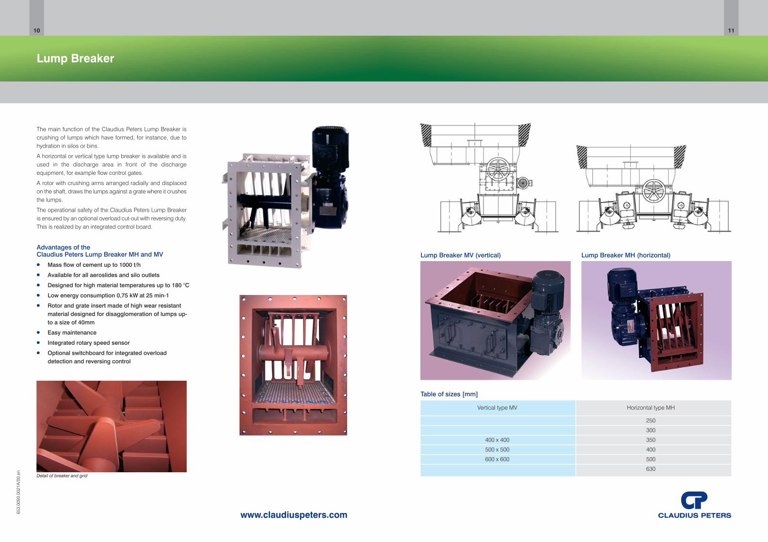
The main function of the Claudius Peters Lump Breaker iscrushing of lumps which have formed, for instance, due tohydration in silos or bins.
A horizontal or vertical type lump breaker is available and isused in the discharge area in front of the dischargeequipment, for example flow control gates.
A rotor with crushing arms arranged radially and displacedon the shaft, draws the lumps against a grate where it crushesthe lumps.
The operational safety of the Claudius Peters Lump Breakeris ensured by an optional overload cut-out with reversing duty.This is realized by an integrated control board.
Advantages of theClaudius Peters Lump Breaker MH and MV● Mass flow of cement up to 1000 t/h
● Available for all aeroslides and silo outlets
● Designed for high material temperatures up to 180 °C
● Low energy consumption 0,75 kW at 25 min-1
● Rotor and grate insert made of high wear resistantmaterial designed for disagglomeration of lumps up-to a size of 40mm
● Easy maintenance
● Integrated rotary speed sensor
● Optional switchboard for integrated overloaddetection and reversing control
Detail of breaker and grid
653.
0093
.002
1A/0
0.en
10
www.claudiuspeters.com
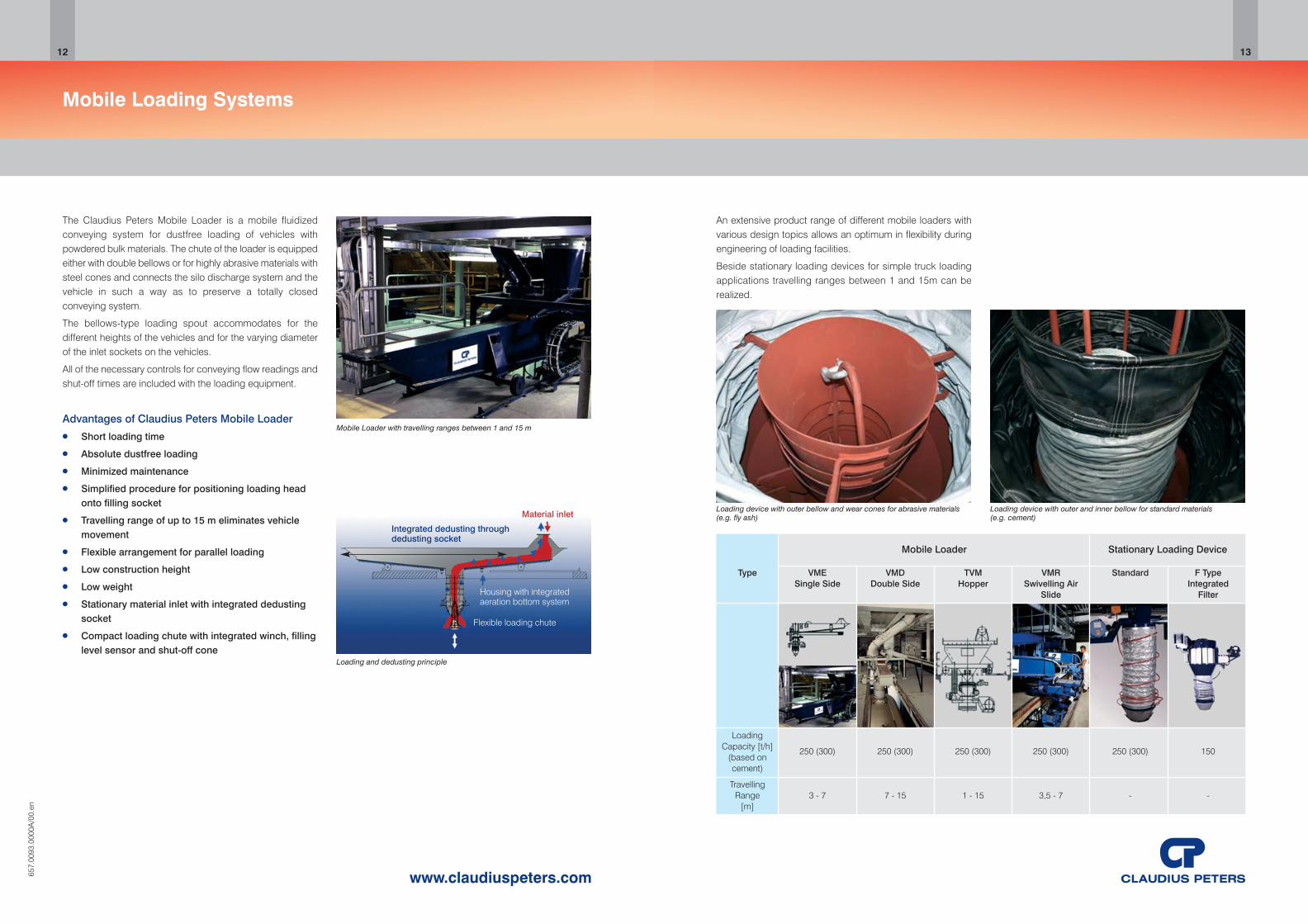
Table of sizes [mm]
Vertical type MV Horizontal type MH
250
300
400 x 400 350
500 x 500 400
600 x 600 500
630
Lump Breaker MH (horizontal)Lump Breaker MV (vertical)
11
Mobile Loading Systems
Mobile Loader with travelling ranges between 1 and 15 m
The Claudius Peters Mobile Loader is a mobile fluidizedconveying system for dustfree loading of vehicles withpowdered bulk materials. The chute of the loader is equippedeither with double bellows or for highly abrasive materials withsteel cones and connects the silo discharge system and thevehicle in such a way as to preserve a totally closedconveying system.
The bellows-type loading spout accommodates for thedifferent heights of the vehicles and for the varying diameterof the inlet sockets on the vehicles.
All of the necessary controls for conveying flow readings andshut-off times are included with the loading equipment.
Advantages of Claudius Peters Mobile Loader● Short loading time
● Absolute dustfree loading
● Minimized maintenance
● Simplified procedure for positioning loading headonto filling socket
● Travelling range of up to 15 m eliminates vehiclemovement
● Flexible arrangement for parallel loading
● Low construction height
● Low weight
● Stationary material inlet with integrated dedustingsocket
● Compact loading chute with integrated winch, fillinglevel sensor and shut-off cone
657.
0093
.000
0A/0
0.en
12
www.claudiuspeters.com
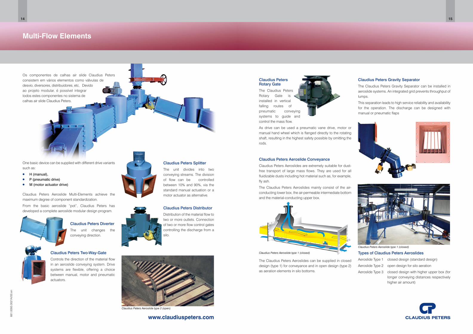
An extensive product range of different mobile loaders withvarious design topics allows an optimum in flexibility duringengineering of loading facilities.
Beside stationary loading devices for simple truck loadingapplications travelling ranges between 1 and 15m can berealized.
Loading device with outer bellow and wear cones for abrasive materials (e.g. fly ash)
Loading device with outer and inner bellow for standard materials (e.g. cement)
13
Loading and dedusting principle
Housing with integratedaeration bottom system
Integrated dedusting through dedusting socket
Material inlet
Flexible loading chute
Mobile Loader Stationary Loading Device
Type VME VMD TVM VMR Standard F TypeSingle Side Double Side Hopper Swivelling Air Integrated
Slide Filter
LoadingCapacity [t/h] 250 (300) 250 (300) 250 (300) 250 (300) 250 (300) 150
(based oncement)
TravellingRange 3 - 7 7 - 15 1 - 15 3,5 - 7 - -
[m]
Multi-Flow Elements
Os componentes de calhas air slide Claudius Petersconsistem em vários elementos como válvulas dedesvio, diversores, distribuidores, etc. Devidoao projeto modular, é possível integrartodos estes componentes no sistema decalhas air slide Claudius Peters.
Claudius Peters Splitter
The unit divides into twoconveying streams. The divisionof flow can be controlledbetween 10% and 90%, via thestandard manual actuation or amotor actuator as alternative.
Claudius Peters Distributor
Distribution of the material flow totwo or more outlets. Connectionof two or more flow control gatescontrolling the discharge from asilo.
Claudius Peters Aeroslide Multi-Elements achieve themaximum degree of component standardization.
From the basic aeroslide “pot”, Claudius Peters hasdeveloped a complete aeroslide modular design program.
Claudius Peters Diverter
The unit changes theconveying direction.
One basic device can be supplied with different drive variantssuch as:
● H (manual), ● P (pneumatic drive)● M (motor actuator drive)
Claudius Peters Two-Way-Gate
Controls the direction of the material flowin an aeroslide conveying system. Drivesystems are flexible, offering a choicebetween manual, motor and pneumaticactuators.
661.
0093
.002
1A/0
0.en
Claudius Peters Aeroslide type 1 (closed)
Claudius Peters Aeroslide type 2 (open)
Claudius PetersRotary Gate
The Claudius PetersRotary Gate isinstalled in verticalfalling routes ofpneumatic conveyingsystems to guide andcontrol the mass flow.
As drive can be used a pneumatic vane drive, motor ormanual hand wheel which is flanged directly to the rotatingshaft, resulting in the highest safety possible by omitting therods.
Claudius Peters Aeroslide Conveyance
Claudius Peters Aeroslides are extremely suitable for dust-free transport of large mass flows. They are used for allfluidizable dusts including hot material such as, for example,fly ash.
The Claudius Peters Aeroslides mainly consist of the air-conducting lower box, the air-permeable intermediate bottomand the material-conducting upper box.
The Claudius Peters Aeroslides can be supplied in closeddesign (type 1) for conveyance and in open design (type 2)as aeration elements in silo bottoms.
Claudius Peters Aeroslide type 1 (closed) Types of Claudius Peters Aeroslides
Aeroslide Type 1 closed design (standard design)
Aeroslide Type 2 open design for silo aeration
Aeroslide Type 3 closed design with higher upper box (forlonger conveying distances respectivelyhigher air amount)
1514
www.claudiuspeters.com
Claudius Peters Gravity Separator
The Claudius Peters Gravity Separator can be installed inaeroslide systems. An integrated grid prevents throughput oflumps.
This separation leads to high service reliability and availabilityfor the operation. The discharge can be designed withmanual or pneumatic flaps
Rotary Feeder DKZ
1716
www.claudiuspeters.com421.
0093
.001
4A/0
0.en
The Claudius Peters Rotary Feeder DKZ is based on theprinciple of the double chamber design and can be usedalternatively to the Claudius Peters silo discharge devicesapplying the fluidization principle. The Rotary Feeder DKZ isused wherever bulk solids have to be discharged in acontrolled and dosed manner from silos and bins. Due to itscompact design and the resulting low constructional height,the rotary feeder is excellently suited as dosing element forloading plants, discharge device for mixing plants or feedingof packing plants. Contrary to vertical rotary feeders, theRotary Feeder DKZ is equipped with an upper and a lowerchamber. This way an uncontrolled discharge is prevented.Inlet and outlet lie one above / below the other.
Advantages of Claudius Peters Rotary Feeder DKZ● Low construction height
● Minimized gaps, thus optimum sealing behaviour
● Sealing strips can be adjusted optimally
● Easy maintenance by simple replacement of sealingstrips
● Maintenance at low maintenance costs
● Flexible throughput capacities by optionalfrequency converter at the drive
Inlet area with adjustable sealing strips
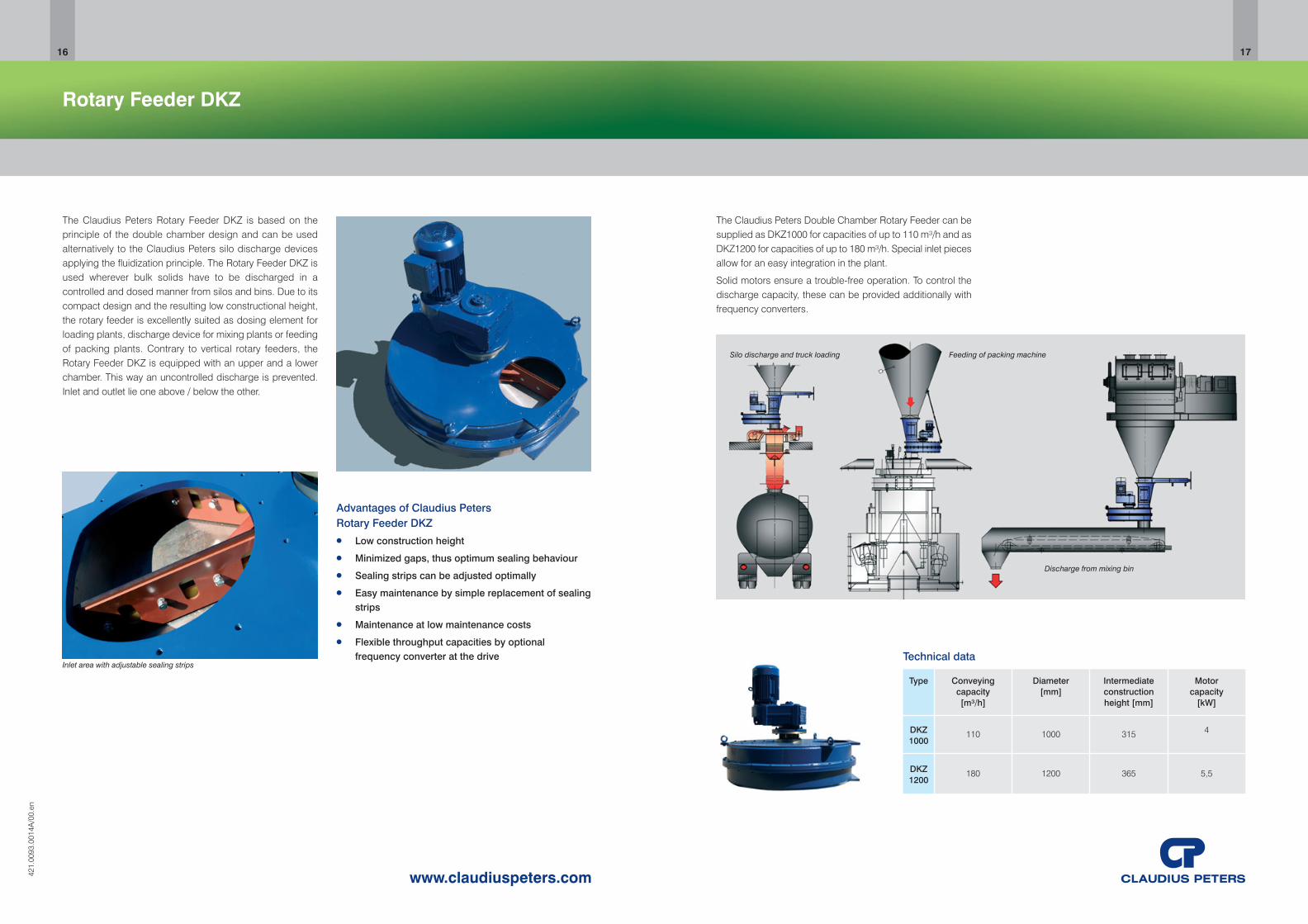
The Claudius Peters Double Chamber Rotary Feeder can besupplied as DKZ1000 for capacities of up to 110 m³/h and asDKZ1200 for capacities of up to 180 m³/h. Special inlet piecesallow for an easy integration in the plant.
Solid motors ensure a trouble-free operation. To control thedischarge capacity, these can be provided additionally withfrequency converters.
Technical data
Silo discharge and truck loading Feeding of packing machine
Discharge from mixing bin
Type Conveying Diameter Intermediate Motor capacity [mm] construction capacity[m³/h] height [mm] [kW]
DKZ 110 1000 315 41000
DKZ 180 1200 365 5,51200
Rotary Feeder TWA
1918
www.claudiuspeters.com421.
0093
.001
5A/0
0.en
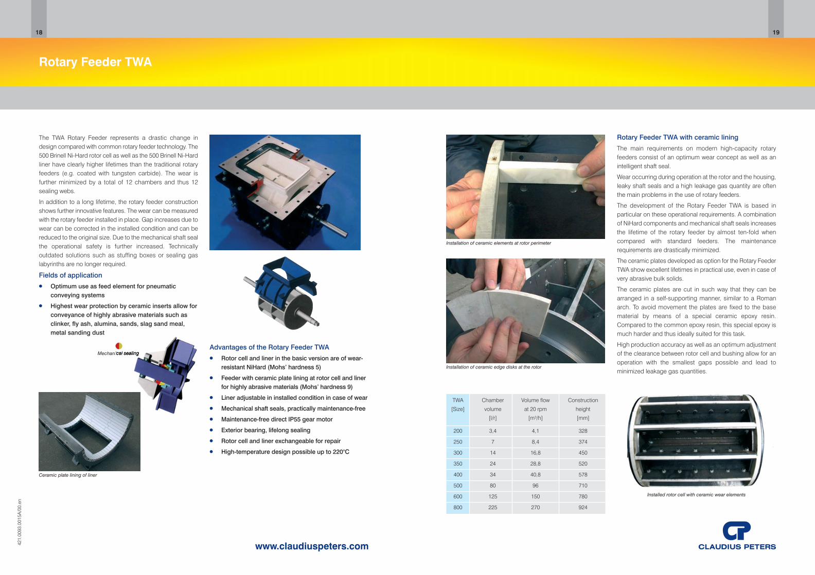
The TWA Rotary Feeder represents a drastic change indesign compared with common rotary feeder technology. The500 Brinell Ni-Hard rotor cell as well as the 500 Brinell Ni-Hardliner have clearly higher lifetimes than the traditional rotaryfeeders (e.g. coated with tungsten carbide). The wear isfurther minimized by a total of 12 chambers and thus 12sealing webs.
In addition to a long lifetime, the rotary feeder constructionshows further innovative features. The wear can be measuredwith the rotary feeder installed in place. Gap increases due towear can be corrected in the installed condition and can bereduced to the original size. Due to the mechanical shaft sealthe operational safety is further increased. Technicallyoutdated solutions such as stuffing boxes or sealing gaslabyrinths are no longer required.
Fields of application● Optimum use as feed element for pneumatic
conveying systems
● Highest wear protection by ceramic inserts allow forconveyance of highly abrasive materials such asclinker, fly ash, alumina, sands, slag sand meal,metal sanding dust
Advantages of the Rotary Feeder TWA ● Rotor cell and liner in the basic version are of wear-
resistant NiHard (Mohs’ hardness 5)
● Feeder with ceramic plate lining at rotor cell and linerfor highly abrasive materials (Mohs’ hardness 9)
● Liner adjustable in installed condition in case of wear
● Mechanical shaft seals, practically maintenance-free
● Maintenance-free direct IP55 gear motor
● Exterior bearing, lifelong sealing
● Rotor cell and liner exchangeable for repair
● High-temperature design possible up to 220°C
Ceramic plate lining of liner
Mechanical sealing
Installation of ceramic elements at rotor perimeter
Installation of ceramic edge disks at the rotor
TWA Chamber Volume flow Construction
[Size] volume at 20 rpm height
[l/r] [m³/h] [mm]
200 3,4 4,1 328
250 7 8,4 374
300 14 16,8 450
350 24 28,8 520
400 34 40,8 578
500 80 96 710
600 125 150 780
800 225 270 924
Rotary Feeder TWA with ceramic lining
The main requirements on modern high-capacity rotaryfeeders consist of an optimum wear concept as well as anintelligent shaft seal.
Wear occurring during operation at the rotor and the housing,leaky shaft seals and a high leakage gas quantity are oftenthe main problems in the use of rotary feeders.
The development of the Rotary Feeder TWA is based inparticular on these operational requirements. A combinationof NiHard components and mechanical shaft seals increasesthe lifetime of the rotary feeder by almost ten-fold whencompared with standard feeders. The maintenancerequirements are drastically minimized.
The ceramic plates developed as option for the Rotary FeederTWA show excellent lifetimes in practical use, even in case ofvery abrasive bulk solids.
The ceramic plates are cut in such way that they can bearranged in a self-supporting manner, similar to a Romanarch. To avoid movement the plates are fixed to the basematerial by means of a special ceramic epoxy resin.Compared to the common epoxy resin, this special epoxy ismuch harder and thus ideally suited for this task.
High production accuracy as well as an optimum adjustmentof the clearance between rotor cell and bushing allow for anoperation with the smallest gaps possible and lead tominimized leakage gas quantities.
Installed rotor cell with ceramic wear elements

Intelligent maintenance concept
For cleaning of the rotary gate and for inspection of the gatesealing, the housing is equipped with a large inspectioncover. Replacement of the wear parts (wear plate and gatesealing) can take place while the rotary gate remains installedby disassembling the drive cover or the opposite inspectionlid.
Lubrication of the bearings or the drive is not necessary.
The end positions can be precisely adjusted and can beindicated by limit switches integrated in the drive.
Process Technology
The material falling vertically is guided to the free outlet viathe wear plate inclined by 45°. The sealing of the gate iscovered by the gate on all sides so that the sealing isprotected optimally against the wear caused by the bulkmaterial flow.
The motor-driven variant is equipped with a handwheel and,if requested, with an integrated drive control system. The drivecontrol includes an interlockable local control box and reversecontactors.
The pneumatic drive variant can also be adjusted manually bymeans of a wrench via a square.
Summary
Due to its modular and dust-tight design, Claudius PetersRotary Gate is excellently suited for use as a branching anddistributing device in pneumatic conveyor systems. The gateis characterized by high availability, long service life of thewear parts and easy maintenance.
Suited for all types of regular drives, the Claudius PetersRotary Gate can be easily integrated in all plants.
The possibility to position the electric drive control with localcontrol panel directly at the actuating drive allows for a simpleand low-cost integration in the plant master control.
Rotary Gate
The Claudius Peters Rotary Gate is installed in vertical fallingroutes of pneumatic conveying systems to guide and controlthe mass flow.
One basic device can be supplied with different drive variantssuch as:
● H (manual),
● P (pneumatic drive)
● M (motor actuator drive)
The drive is flanged directly to the rotating shaft, resulting inthe highest safety possible by omitting the rods.
The drives are designed with sufficient reserves so that evenunder aggravated conditions a safe operation is ensured.
The Claudius Peters Rotary Gate consists of a cylindricalhousing. Sealing of one outlet each is carried out by anadjustable gate. By turning the drive shaft, the gate shifts fromone material outlet to the other. A flexible sealing, which ispressed against the housing wall by a compression spring,provides a dust-tight sealing of the locked outlet.
The drive is equipped with integrated micro switches whichguarantee a safe positioning of the sliding gate.
Advantages of Claudius Peters Rotary Gate● Compact drive unit incl. all necessary monitoring
devices
● Alternative feeding of two vertical material routes
● Dust-tight sealing of the closed outlet, even if thewear of the sealing increases
● Low flow resistance
● Simple replacement of wear parts
● Long service life
● High flexibility due to the modular design
● Manual adjustment for emergency operation
637.
0093
.002
1A/0
0.en
2120
www.claudiuspeters.com

Silo Aeration modification
619.
0093
.002
1A/0
0.en
2322
www.claudiuspeters.com
Negative characteristic● Leakage air during the switching-over procedure
● Only fixed aeration cycles possible
● No individual and separate operation possible
● Mechanical distribution system leads to wear due torotating parts
Positive characteristic● No leakage air during the switching-over procedure.
● Easy replacement of flaps
● Aeration sequences can be adapted to theoperating conditions by a PLC System
● Process control is completely mounted andprogrammed in the switchboard.
● Separate program for the residual discharge
Customer Benefits● High operation flexibility
● High plant reliability
● Less wear parts
Conversion set for Claudius Peters Siloswith mechanical air distribution systems
Claudius Peters Silos of former construction typeshave been equipped with an air distributingsystem with motorized rotating distributor.
Modern Claudius Peters Silo Aeration bottoms areequipped with air distribution systems controlledby electro-pneumatically actuated intermediateflaps with position indication.
Chamber segments Outer ring segments
Chamber segments Outer ring segments
Former air distribution withmechanical distributor
New installation of air distribution system for siloaeration including electro pneumatic flaps
Silo aeration bottom with porous stones(before modification)
Claudius Peters Aeroslide type 2 (open)
Conversion SET for Claudius Peters Silos withporous plates for Silo aeration
Claudius Peters Silos of former construction types have beeequipped with porous plates for material fluidization.
All modern Claudius Peters Silos are quipped with aerationbottoms completely covered with open airslides, which areradially arranged and aerated in sections. Economicoperation is ensured by a control system.
Claudius Peters has realized a lot of modifications of theseexisting “OLD STYLED” silo types.
Silos of older construction types can easily and efficiently bemodernized by means of pneumatic air distribution and a flapcontrol.
Silo aeration bottom and sequence
Advantages● Reduction of maintenance time due to simple
replacement of aeration fabric
● High operation reliability
● Reduction of maintenance costs
● Aeration sequences can be adapted to theoperating conditions by a PLC system
● Process control is completely mounted andprogrammed in the switchboard
● Separate program for the residual dischargeSilo aeration bottom with aeroslides
(after modification)

Silo Air flow controller - AFC
2524
www.claudiuspeters.com619.
0093
.002
2A/0
0.en
Positive characteristics● Reduction of fluctuating material discharge due to
constant aeration conditions
● Less wear at discharge components due tominimized velocity of air/material flow
● Optimization of process conditions in case ofchanged material or discharge rates
● Usable for all silo types also for other brands
Silo Air Flow Controller AFC – Reduction of pulsating material discharge
For all silos, which do not have an expansion chambertechnology, it comes with high filling conditions to theproblem that aeration air cannot escape by the materialcolumn. The consequence is a too high fluidization of thematerial and fluctuating pressure conditions at the outlet. Thisleads frequently to a pulsating material discharge.
The Claudius Peters Air Flow Controller - AFC represents forthis the suitable system, in order to reduce the materialfluctuations. In combination with a flow control gate withcontrolled function this system can be integrated optimallyinto existing plants. The Claudius Peters AFC consists of 3main components:
● Adjustable blow-off flap
● Electronic push button switch
● Controller
➀ Control flap ➁ Pressure transmitter ➂ Local control panel
Function mode
A blower compresses the required aeration air into the silobottom. The bulk material begins to come into a fluidizingphase. Supported by the gravity force of the bulk materialcolumn the material flows to the outlet at the center of the silo-bottom by means of gravitation.
For an even material discharge the aeration pressurerepresents the main parameter. The desired pressure setpoint is adjustable at the control unit and can be optimizedduring process operation. This parameter is kept constantduring the entire material discharge time.
A rise of the aeration pressure due to too high fluidization ofthe material in the silo leads to controlled blow out of aerationair by a control flap across a dedusting piping into an exhaustair system. The pressure reduces to the set point.
Beside an integration in silos without expansion chamber alsoexisting chamber silos can be equipped with the AFC systemafterwards. In that case also an optimized regulation of thechamber level is possible.
This system allows an integration in all existing silos especiallyfor those without chamber dedusting.
26
www.claudiuspeters.com
Stationary Loading Device
Advantages of Claudius Peters Stationary LoadingDevice ● For simple loading procedures without travelling
ranges
● Short loading time
● Absolute dust-free loading
● Minimum maintenance
● Low construction height
● Low weight
● Stationary material inlet with integrated dedustingsocket
● Compact loading chute with integrated winch, fillinglevel sensor and shut-off cone
● Electrical filling sensor and vibrator for additionalspout cleaning as option available
Lifted position - cone closed In operation - cone open
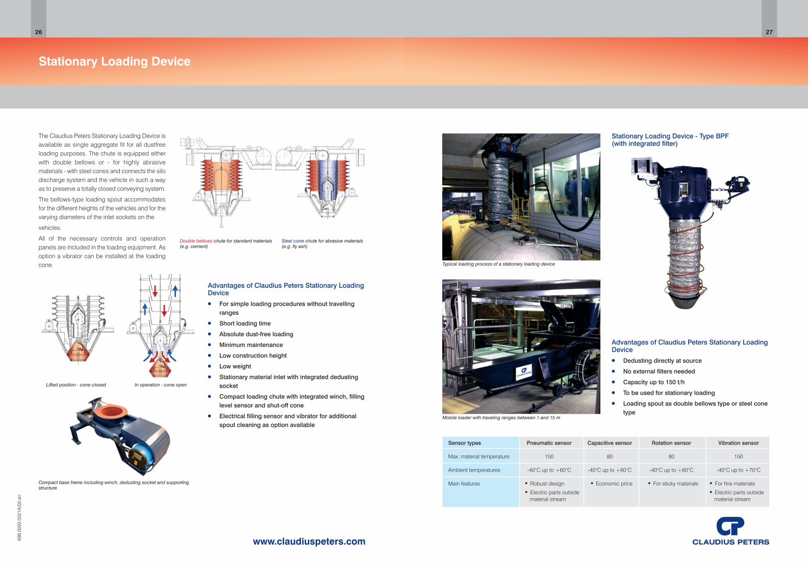
The Claudius Peters Stationary Loading Device isavailable as single aggregate fit for all dustfreeloading purposes. The chute is equipped eitherwith double bellows or - for highly abrasivematerials - with steel cones and connects the silodischarge system and the vehicle in such a wayas to preserve a totally closed conveying system.
The bellows-type loading spout accommodatesfor the different heights of the vehicles and for thevarying diameters of the inlet sockets on the
vehicles.
All of the necessary controls and operationpanels are included in the loading equipment. Asoption a vibrator can be installed at the loadingcone.
Steel cone chute for abrasive materials (e.g. fly ash)
Double bellows chute for standard materials (e.g. cement)
Compact base frame including winch, dedusting socket and supportingstructure
696.
0093
.002
1A/0
0.en
Stationary Loading Device - Type BPF(with integrated filter)
Typical loading process of a stationary loading device
Mobile loader with traveling ranges between 1 and 15 m
Advantages of Claudius Peters Stationary LoadingDevice ● Dedusting directly at source
● No external filters needed
● Capacity up to 150 t/h
● To be used for stationary loading
● Loading spout as double bellows type or steel conetype
Sensor types Pneumatic sensor Capacitive sensor Rotation sensor Vibration sensor
Max. material temperature 150 80 80 150
Ambient temperatures -40°C up to +60°C -40°C up to +60°C -40°C up to +60°C -40°C up to +70°C
Main features ● Robust design ● Economic price ● For sticky materials ● For fine materials● Electric parts outside ● Electric parts outside
material stream material stream
27

Storage Silo CC
2928
www.claudiuspeters.com619.
0093
.002
3A/0
0.en
Advantages of Claudius Peters CC Silo ● Silo principle first in / first out
● No dead material inside silo
● Excellent reclaim rate
● Application for small silo units
● Application for materials whose fluidization islimited
● Silo aeration system can be used for concrete orsteel silos
Sectionwise aeration to silo outlets
The Storage Silo CC is a silo type for fluidizable mineral bulkmaterials. CC stands for “conventional cone" silo which is, ingeneral, designed for silo diameters of 6 – 14 m. Standardaeration bottoms 3 m, 3,5 m, 5,5 m and 7,5 m are available.
Silo storage volumes of up to 5000m3 can be realized.
The standard design is suitable for the storage of
● Easy flowing bulk materials, like cement or rawmeal
● Hardly flowing bulk materials like fly ash
Other bulk materials, like gypsum, quick lime, lime hydrateand others, can also be stored in the Storage Silo CC.
Discharge tunnel to center outlet
Flow principle of Claudius Peters CC Silo
Storage Silo CC under construction
Effective Aeration Concept
The aeration sectors are aerated alternately for a certain timeduring the discharge procedure. This aeration/dischargesequence is independent from the filling procedure. The maintarget of the aeration technique is a controlled discharge withhighest silo reclaim rate.
A blower compresses the required aeration air into the silobottom. An integrated aeration air system controlled by shut-off flaps, aerates the two bottom sectors. The bulk materialbegins to come into a fluidizing phase. Supported by thegravitational force of the bulk material column the materialflows along the inclined aeroslide to the outlet at the center ofthe CC-bottom by means of gravity.
Claudius Peters discharge equipment under the silo like flatshut off gates, feed boxes and flow control gates guaranteea controlled discharge flow.
Discharge tunnel under silo cone leads to continuous discharge conditions at outlet

www.claudiuspeters.com
Two-Way Gate
Advantages of Claudius Peters Two-Way Gate● Alternative feeding or distribution to two conveying
routes of one aeroslide system
● Dust-tight sealing of the closed outlet
● Low flow resistance
● Flexible arrangement of the horizontal and/orvertical outlets
● Simple replacement of wear parts
● Long service life
● High flexibility due to the modular design
Operation principle of Claudius Peters Two-Way Gate, used as bottomdischarger
The Claudius Peters Two-Way Gate is installed in aeroslidesystems to guide and control the mass flow.
The Claudius Peters Two-Way Gate consists of a cylindricalhousing. Sealing of one outlet each is carried out by anadjustable gate. By turning the drive shaft, the gate shifts fromone material outlet to the other. A flexible sealing ensures thatthe outlet is sealed dust-tight.
The drives can be pneumatic, motoric or manual and aredesigned with sufficient reserves so that even underaggravated conditions a safe operation is ensured.
For cleaning of the Two-Way Gate and for inspection of thegate sealing, the housing is equipped with a large inspectioncover. Replacement of the wear parts (aeration fabric andgate sealing) can take place while the Two-Way Gate remainsinstalled by disassembling the top cover or the bottom.
Lubrication of the bearings or the drive is not necessary. Theend positions can be precisely adjusted and can be indicatedby limit switches integrated in the drive.
596.
0093
.002
1A/0
0.en
Type MANUAL Type PNEU Type MOT Manually by lever Pneumatically by Motor-driven by
electro-pneumatic actuator drive rotary vane drive (incl. manual handwheel)
30
Process Technology
The design of the gate allows an unrestricted flow to the mainconveying line, thus avoiding an increase of the flowresistance when conveying via this line. In front of the closedgate, the bulk material is directed along the round wall to thefree outlet. The sealing of the gate is covered by the gate onall sides so that the sealing is protected optimally against thewear caused by the bulk material flow.
The aeration bottom ensures a continuous fluidization of thebulk material.
Summary
Due to its modular and low-flow-loss design, Claudius PetersTwo-Way Gate is excellently suited for use as a branching anddistributing device in pneumatic conveyor systems. The gateis characterized by high availability, long service life of thewear parts and easy maintenance.
Suited for all types of regular drives, the Claudius Peters Two-Way Gate can be easily integrated in all plants. The possibilityto position the electric drive control with local control paneldirectly at the actuating drive allows for a simple and low-costintegration in the plant master control.
31
www.claudiuspeters.com
Two-Way Valve
Advantages of Claudius Peters Two-Way Valve● Feeding to two different conveying routes
● Low pressure loss
● Symmetric form
● Simple exchange of wear parts
● Long service life
● Compact design
● High positioning accuracy
● Simple installation
● Precise movement to the sealing position
● End positions of the valve disk are defined by thelimit switches integrated in the drive
433.
0093
.002
1A/0
0.en
Intelligent maintenance concept● For dismantling of the wear plate and the valve disk,
the housing can be opened and swung to the side
● Automatic lubrication of the rotary shaft
● For cleaning of the valve as well as for checking ofthe wear plate and the valve disk, the housing isequipped with a handhole cover
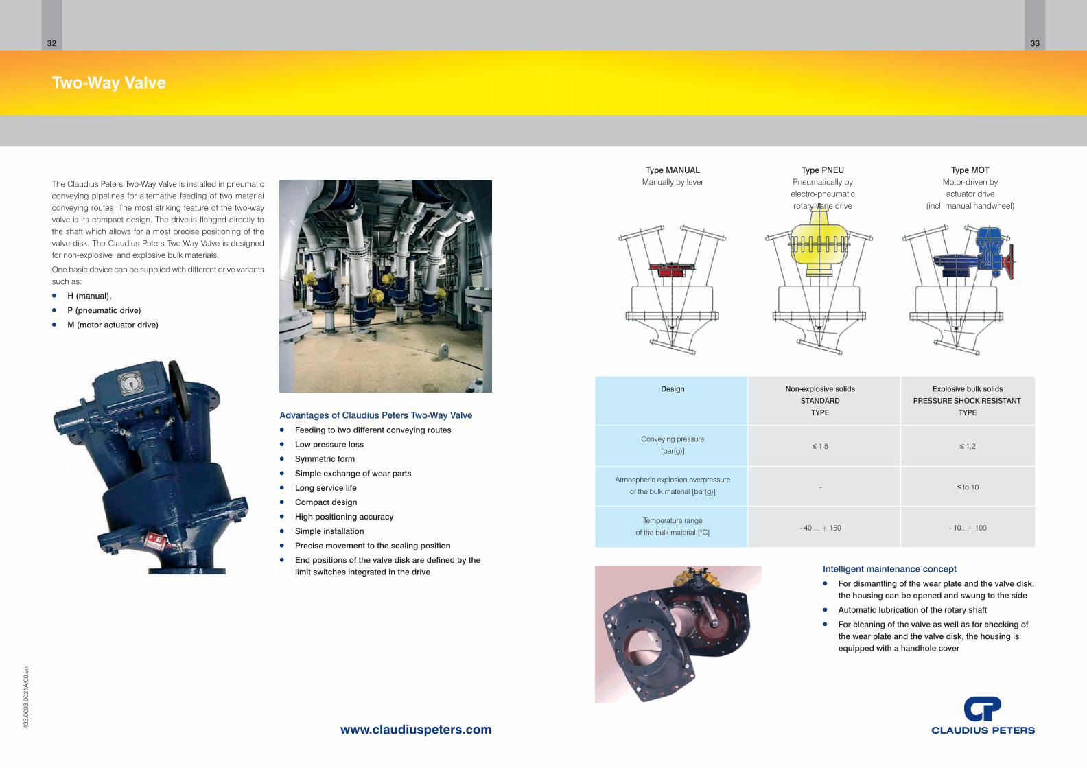
Type MANUAL Type PNEU Type MOT Manually by lever Pneumatically by Motor-driven by
electro-pneumatic actuator drive rotary vane drive (incl. manual handwheel)
32 33
The Claudius Peters Two-Way Valve is installed in pneumaticconveying pipelines for alternative feeding of two materialconveying routes. The most striking feature of the two-wayvalve is its compact design. The drive is flanged directly tothe shaft which allows for a most precise positioning of thevalve disk. The Claudius Peters Two-Way Valve is designedfor non-explosive and explosive bulk materials.
One basic device can be supplied with different drive variantssuch as:
● H (manual),
● P (pneumatic drive)
● M (motor actuator drive)
Design Non-explosive solids Explosive bulk solids
STANDARD PRESSURE SHOCK RESISTANT
TYPE TYPE
Conveying pressure≤ 1,5 ≤ 1,2
[bar(g)]
Atmospheric explosion overpressure - ≤ to 10
of the bulk material [bar(g)]
Temperature range - 40 ... + 150 - 10...+ 100
of the bulk material [°C]
Summary
The Claudius Peters solid X-Pump is a very compact unit dueto the two-sided bearing. The machinery runs extremely quietand is characterized by very low power consumption andreduced pulsation during operation. The wear parts can beeasily replaced, and the pump is suitable for a very widerange of applications and materials.
To sum it up it can be said that the Claudius Peters X-Pumpis an excellent bulk feeding system for safety operationprocesses with highest plant reliability.
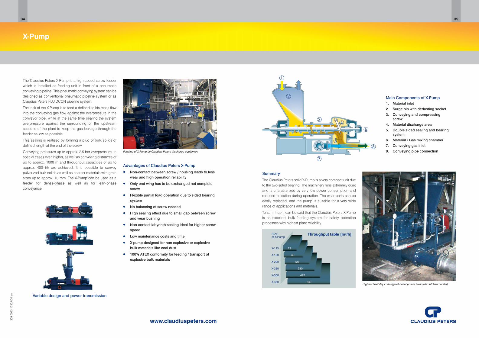
Main Components of X-Pump1. Material inlet
2. Surge bin with dedusting socket
3. Conveying and compressingscrew
4. Material discharge area
5. Double sided sealing and bearingsystem
6. Material / Gas mixing chamber
7. Conveying gas inlet
8. Conveying pipe connection
Highest flexibility in design of outlet points (example: left hand outlet)
➀
➁
➂➃
➄
➆
➇➅
X-Pump
Advantages of Claudius Peters X-Pump● Non-contact between screw / housing leads to less
wear and high operation reliability
● Only end wing has to be exchanged not completescrew
● Flexible partial load operation due to sided bearingsystem
● No balancing of screw needed
● High sealing effect due to small gap between screwand wear bushing
● Non-contact labyrinth sealing ideal for higher screwspeed
● Low maintenance costs and time
● X-pump designed for non explosive or explosivebulk materials like coal dust
● 100% ATEX conformity for feeding / transport ofexplosive bulk materials
Feeding of X-Pump by Claudius Peters discharge equipment
Variable design and power transmission
309.
0093
.103
0A/0
0.en
The Claudius Peters X-Pump is a high-speed screw feederwhich is installed as feeding unit in front of a pneumaticconveying pipeline. This pneumatic conveying system can bedesigned as conventional pneumatic pipeline system or asClaudius Peters FLUIDCON pipeline system.
The task of the X-Pump is to feed a defined solids mass flowinto the conveying gas flow against the overpressure in theconveyor pipe, while at the same time sealing the systemoverpressure against the surrounding or the upstreamsections of the plant to keep the gas leakage through thefeeder as low as possible.
This sealing is realized by forming a plug of bulk solids ofdefined length at the end of the screw.
Conveying pressures up to approx. 2.5 bar overpressure, inspecial cases even higher, as well as conveying distances ofup to approx. 1000 m and throughput capacities of up toapprox. 400 t/h are achieved. It is possible to conveypulverized bulk solids as well as coarser materials with grainsizes up to approx. 10 mm. The X-Pump can be used as afeeder for dense-phase as well as for lean-phaseconveyance.
34 35
www.claudiuspeters.com

The information contained within this brochure is deemed to be correct at the timeof going to press. Due to the policy of continued improvement, we reserve the rightto change any specification without prior notice.ERRORS & OMISSIONS EXCEPTED
CP Components GB October 2013/Issue 1 www.claudiuspeters.com
CALCINING | COOLING | DISPATCH
DOSING | DRY BLENDING | DRYING
GRINDING | PACKING
PNEUMATIC CONVEYING
PULVERIZED FUEL SUPPLY
SILO SYSTEMS
STOCKYARD SYSTEMS
ALUMINA HANDLING SYSTEMS
MARINE POWDER HANDLING
TURNKEY PROJECTS
We know how
HEADQUARTERS
Claudius Peters Technologies GmbHSchanzenstraße 40,D-21614 Buxtehude,Germany.Tel: +49 (0) 4161 706-0Fax: +49 (0) 4161 [email protected]
Claudius Peters Technologies SAS34 Avenue de Suisse,F-68316 Illzach,France.Tel: +33 (0)3 89 31 33 00Fax: +33 (0)3 89 61 95 [email protected]
Claudius Peters (Americas) Inc. - Texas | Claudius Peters (China) Ltd. - Beijing & Hong Kong | Claudius Peters (UK) Ltd. - London | Claudius Peters (Italiana) srl. - BergamoClaudius Peters (Iberica) S.A. - Madrid | Claudius Peters România S.R.L. - Sibiu | Claudius Peters (do Brasil) Ltda. - São Paulo
Claudius Peters (Asia Pacific) Pte. Ltd. - Singapore | Claudius Peters (India) Pvt. Ltd. - Mumbai