composite patch repair for marine and civil engineering...
TRANSCRIPT

1
FP7-SST-2008-RTD-1 Sustainable Surface Transport
Co-Patch
Composite Patch Repair
for Marine and Civil Engineering Infrastructure Applications
General Overview of the Project
E-LASS Kick-off + E-LASS & MESA workshop, Borås, Sweden, 8-9 October 2013

2
Co-Patch Consortium
3 partners from UK, 2 partners from France, Greece, Norway, Portugal and Spain, 1 from Croatia and Italy
PROJECT COORDINATOR: National Technical University of Athens, Shipbuilding Technology Laboratory
January 2010 – April 2013 (40 months)
Total budget 5,285,000 Euro

3
Composite patches have been applied successfully on naval ships, offshore platforms and civil constructions
Type 21 Frigate (Amazon class)
Repair of the main deck RAN Adelaide Class Frigate
Repair of the main deck
Bridge
Pottawattamie County, USA
FPSO (Floating Production Storage and Offloading) (Norway)
Repair of the corroded deck floor and of the cargo tank bulkhead - DNV

4
Main objective of the project: Definition of a new effective repair/reinforcement method for large steel structures with defects and demonstrate that composite patch repairs or reinforcements can be environmentally stable and that they can be used as permanent repair measures
Advantages with respect to conventional repair/reinforcement technologies:
• No hot work • Application ‘in situ’ • No stress concentrations • Low added weight
Repair of damages caused by: • Fatigue • Corrosion
Upgrade of existent structures for: • Sustain new loads • Mitigating initial structural deficiencies
Critical aspect of composite patches: • Long term performance ???
Field of application: • Marine (vessels, platforms, ...) • Civil (bridges, cranes, ...)

5
Specification of application cases BV
Various repair application cases were specified
A stakeholder forum was established to discuss and agree the business and regulatory
implications of introducing composite patch repair (more than 30 members)
Reinforcement of
cross deck plating in
container ships
Civil applications
cases
Defects at bilge
hopper plates
Reinforcement in way
of structural details for
passage of stiffeners

6
Laboratory testing NTUA
Composite materials characterization
Single Lap Shear tests
Various composite configurations: HLU-C/V, VI-C/V & VI-C/E
Two surface preparation methods: Grit Blasting (GB) & Needle-Gun (NG)
Two aging scenarios: Non-aged & 300 cycles (100 days) aging

7
Laboratory testing NTUA
Composite materials characterization
Single Lap Shear tests
Various composite configurations: HLU-C/V, VI-C/V & VI-C/E
Two surface preparation methods: Grit Blasting (GB) & Needle-Gun (NG)
Two aging scenarios: Non-aged & 300 cycles (100 days) aging
Small scale tests
Patched cracked plates in static tension

8
Laboratory testing NTUA
Composite materials characterization
Single Lap Shear tests
Various composite configurations: HLU-C/V, VI-C/V & VI-C/E
Two surface preparation methods: Grit Blasting (GB) & Needle-Gun (NG)
Two aging scenarios: Non-aged & 300 cycles (100 days) aging
Small scale tests
Patched cracked plates in static tension
Patched corroded plates in static tension

9
Laboratory testing NTUA
Composite materials characterization
Single Lap Shear tests
Various composite configurations: HLU-C/V, VI-C/V & VI-C/E
Two surface preparation methods: Grit Blasting (GB) & Needle-Gun (NG)
Two aging scenarios: Non-aged & 300 cycles (100 days) aging
Small scale tests
Patched cracked plates in static tension
Patched corroded plates in static tension
Patched cracked plates in fatigue
(±100 MPa, f = 2 Hz)
Patch side Back side

10
Laboratory testing NTUA
Composite materials characterization
Single Lap Shear tests
Various composite configurations: HLU-C/V, VI-C/V & VI-C/E
Two surface preparation methods: Grit Blasting (GB) & Needle-Gun (NG)
Two aging scenarios: Non-aged & 300 cycles (100 days) aging
Small scale tests
Patched cracked plates in static tension
Patched corroded plates in static tension
Patched cracked plates in fatigue
(±100 MPa, f = 2 Hz)
4-point bending beam tests

11
Laboratory testing NTUA
Small scale tests - Major conclusions
Needle gun surface treatment proved completely
ineffective
Aging decreases the static strength of unpainted
patched specimens. Properly painted specimens
were not influenced by aging.
Yield initiation load increased by a factor of 2
A non-aged or a properly painted aged patch
fully reinstates the strength of a corroded plate
Fatigue life increased by a factor of up to 5
The sooner the patch is applied, the better
improvement of the fatigue life is accomplished
Crackinitiation
N
a
Nini
af
ai
Nt,u
Nt,p
Nr,u
Nr,p
ap
Crack propagation
After patchingBeforepatching
N

12
Laboratory testing NTUA
Large scale tests
Major conclusions
Double patch case strength exceeds that of intact plate
Single patch cases strength approx. 80% of the intact strength and 165% of the defected
unpatched case (130% for case 2)

13
Monitoring methods and procedures NTNU
An inspection procedure was developed, tailored to the application of patch repairs. A pertinent
checklist was provided to guide the inspector.
Four methods were identified as being most appropriate:
BondMaster (acousto-ultrasound technique), electrical strain gauges, fibre optical Bragg
gratings and optical back scattering reflectometer
14
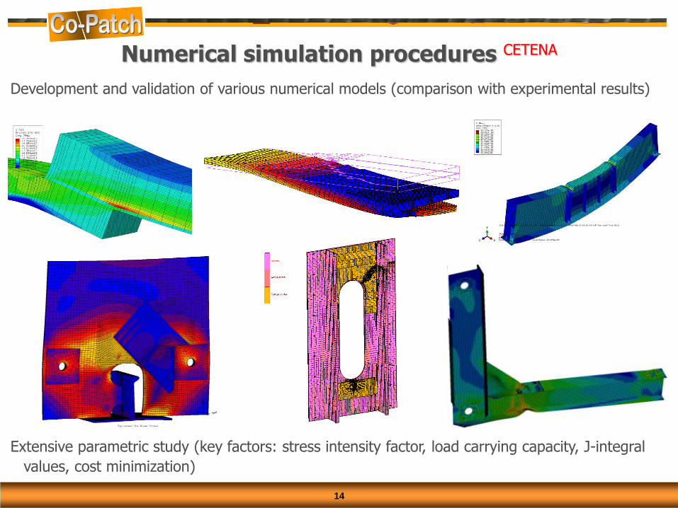
Development and validation of various numerical models (comparison with experimental results)
Extensive parametric study (key factors: stress intensity factor, load carrying capacity, J-integral
values, cost minimization)
Numerical simulation procedures CETENA
15
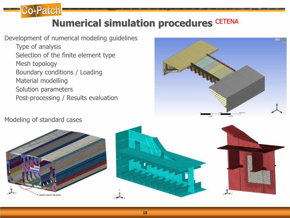
Numerical simulation procedures CETENA
Development of numerical modeling guidelines
Type of analysis
Selection of the finite element type
Mesh topology
Boundary conditions / Loading
Material modelling
Solution parameters
Post-processing / Results evaluation
Modeling of standard cases

16
Test pieces fitted on deck of a seagoing tanker early in the project
failure of bond-line after 16 months due to poor surface preparation and lack of protection
Full scale on site tests BV

17
Full scale on site tests BV
Crack 1 Crack 2 Crack 3 Corroded bulkhead
A catamaran like structure with various defects was specially built (L=6m, B=4.4m, LS=5.15 tons)
Numerical design of patches

18
Full scale on site tests BV
Six hand lay-up and vacuum infused patches (some defects left unpatched)
Test run for 10 months (more than 20000 cycles)
Continuous monitoring with conventional strain gages, FBG and OBR optic strain sensors
All patches remained intact (no degradation, no debonding)
No crack propagation, lower strains on the patched side

19
Guidelines and design procedures AIMEN
Best practice patch repair/reinforcement design and application procedures were developed
Regulatory framework
remarks on survey procedure (conditions, preparations, performance)
a repair and survey time-line for composite repairs is developed by BV
guidelines for design and installation reporting and in-service inspection program
Damage evaluation – check list for inspection
type, location, dimensions, free area, load, environment,
accessibility, NDE, mapping
Patch design
materials selection (fibers, fabric, resin, SR)
dimensions (thickness, shape, configuration, tapering)
manufacturing method (HLU, VI, pre-pregs, direct lamination)
failure modes
Patch application
surface preparation, primers, process, production control
Patch control
steel and patch defects monitoring guidelines
Evaluation of damage
Patch design
Patch application
Patch control
Regulatory framework
Tra
inin
g

20
Training materials and assessment to support skills development within marine and construction
sectors
Application for CSWIP (Certification Scheme for Welding and Inspection Personnel) certification
for course approval is submitted
CSWIP scope includes
Surface preparation
Preparation for installation of composite patch
Application of composite reinforcement
Curing the composite system
Quality control checks
Installer theoretical and practical examinations
Supervisor theoretical examinations
Training programme for personnel TWI
CERTIFICATION SCHEME FOR PERSONNEL
DOCUMENT No. CSWIP- CPRMCS – 23-12 Requirements for the Certification of Installers and Supervisors of Composite Patch Repair for Marine and Civil Structures (CPRMCS)

21
Experimental studies to assess the effect of aging
Experimental studies to define adhesive joints cohesive properties (for FE modelling)
Definition of testing protocols in accordance with industry needs
High strain rate tests
Large-scale fatigue tests
Fire tests
Standardization of regulatory framework
Future research needs for steel-to-composite joints