composite piles with precast enlarged bases driven for...
TRANSCRIPT

24
or about one week after the last of the west abutment piles, which were 130 ft away, had been driven, Settlement points established when the footing was poured showed final settlement of the east abutment was less than 0.25 in.
Transportation Research Record 884
REFERENCE
1. P. Keene. Tolerable Movements of Bridge Foundations. TRB, Transportation Research Record 678, 1978, pp. 1-6.
Composite Piles with Precast Enlarged Bases Driven for Fuel Oil Tank Foundations STANLEY MERJAN
Deep foundations were required for the support of six large fuel oil storage tanks in Queens, New York. A system of 150-ton-capacity composite piles with precast enlarged bases (TPT piles) was selected for the job. An extensive load test program, which included testing of a dogleg pile, was conducted to establish the criteria for pile installation. A variety of installation procedures was required to overcome difficulties in penetrating cumbersome overburden materials to reach the bearing stratum. Hydrostatic loading of the completed tanks showed settlements of less than 0.25 In.
The Power Authority of New York State recently constructed six 6 000 000-gal fuel oil storage tanks for the Astoria Generating Station No. 6 in Queens County, New York City. These tanks each measured 160 ft in diameter by 40 ft high. A fuel oil auxiliary building was also built at this time. All of these structures were designed to be supported on 150-ton-capacity piles. Figure 1 shows the job layout.
CONSIDERATIONS IN SELECTION OF PILE TYPE
The Stone and Webster Engineering Corporation of New York City was the project administrator for the Power Authority and supervised all of the foundation work for the job. They did an extensive subsurface and foundation study to determine the most appropriate support system for this work. Much of the site had been filled in over a number of years. Old drawings were retrieved that showed the location and construction of timber piers and bulkheads that were no longer visibly in evidence. It had been assumed that the remnants of these structures were buried under the fill. This fill contained wood, cinders, and boulders that extended to depths of up to 30-35 ft. Some preliminary excavation at the site in connection with other work revealed the presence of large areas of "subway rock"i i.e., large blocks of mica schist and granite in sizes up to 5 yd' that, in all likelihood, were dumped during the construction of the New York City subways.
The soil profile below the fill was not uniform. In general, it consisted of a layer of soft river silt, varved lenses of silt and sand, dense cemented sands and boulders (hardpan), weathered mica schist, and, finally, bedrock that consisted of mica schist and granite that had recoveries of about 40-60 percent in the upper 5 ft. The water table, which was influenced by the tide variations in the adjoining East River, varied between elevation O and +5.
The total maximum load on each tank mat was of the order of 30 000 tons distributed over an area of approximately 20 000 ft 2 , or 1.5 tons/ft 2 • For less onerous soil profiles, the tank slab design would have governed the pile design capacity. Usu-
ally this would indicate the use of low-capacity piles spaced closely together, such as 30-ton piles at 4-6 in on center. However, the cost of installing any type of pile through the rough fill material and compressible soils into acceptable bearing soils mandated the selection of a high-capaci ty pile in order to limit the tnt.111 nnmhPr nf such units.
A composite pile that had an enlarged base and a capacity of 150 tons was selected to be driven into the dense sand and glacial till below the poorer soils. The enlarged base was needed to develop this high capacity. H-beams or closed-end pipe piles would have to be driven to bedrock to satisfy this design load. The stem of the composite pile was a corrugated shell filled with plain 5000-psi concrete by using type 2 cement for compatibility with the groundwater that had a high salinity because of the adjoining estuary. H-beams would have required an
Figure 1. Test pile location plan.
II I
12 13 14 I I I
H-
.. ~~! ~~ ~ ~
G-
F-
E-
D-
c-
B-
A-
2-
TE ST PILE L EGEN Q IP I. PILE 28 TANK I. IP 2. PILE 87 TANK 3. TP 3. PILE 85 TANK 4.
TP 4. PILE 73 TANK 2.
15 I
16 I
17 I
18 I
19 I
88
0 50 100 200 300
1-U I I
SCALE FEET
20 I

Transportation Research Record 884
expensive (and vulnerable) bitumastic coating to offset potential corrosion; pipe piles would have needed similar treatment or the discounting of the pipe thickness in determining useful pipe capacity. A total of 213 piles were needed for each tank when spaced on a 10-ft grid pattern.
Figure 2. TPT schematic.
6 ·
REBAR
.. SHELL SOCKET
... . 60"
5000 P.S. I. CONCRETE
. <J
2 3"
Figure 3. Wave-equation analysis.
PREPARED BY M.T. DAVISSON, FOUNDATION ENGINEER (URBANA, ILL.) JOB; POWER AUTHORITY OF THE STATE OF NEW YORK
(fl
ti I-
:> 0::
w 0 z <I I-(fl
V5 w 0::
0
~ z b w !;i
LOCATION : · NEW YORK N.Y. PILE: ' A" T.P.T . L ENGTH tEFF.l : 2 .5' 2 M'ANDREL ; COBl/MERJAN HYDRAULIC AREA: 50 IN LENGTH: 70' HAMt.IER : VULCAN 010 ENERGY ; 32500 FT.LBS. EF. ; 75 " HELMET !DRIVING HEADl; 1000 LBS. E: 1.0 CUSHION t HAMMER) ; WOOD K .: l.1 XI06 Le/IN E: 0.50 0510E: 0.10
JSIDE • 0 . 05 CUSHION (Pll,E) ; Q,,.,INT: 0.16 JPOINT; 0.15
2 COMMENTS:" A" T. P.T. 29" x 23 "x 60" WT: 2250L9S. TIP AREA: 415.5 Ill
o•;a1euT10N oF
Tp
100% RU
SOIL RESISTANCE
600
5001----
4
300
::i; 100 5 :J
o-t--~1---+~-1-~-1--+~-1-~-1---1~--+~+-~1---1--5 10 15 20 25 30
HAMMER BLOWS PER INCH
25
CONTRACT FOR PILING WORK
The bid package was for the foundation piling only. The excavation, concrete, and other work were let separately. Bidding documents called for the use of pressure-injected footings to be installed as endbearing units into the dense sand, glacial till, weathered rock, or bedrock. However, the Power Authority agreed to consider bids based on the use of other piling types, including H-piles and composite concrete piles with precast bases. The form of the bid was "lump sum"; the pile capacity was to be guaranteed irrespective of pile length. There was no provision for payment of any costs resulting from installation difficulties.
Underpinning & Foundation Constructers, Inc., of Maspeth, Queens, was the low and successful bidder for this work at $1 931 000. This bid was based on the use of composite piles with precast enlarged bases (TPT piles, a patented piling system licensed for use by Underpinning & Foundation Constructors, Inc.). Another bidder proposed the use of the specified pressure-injected footings for $2 490 000. There were several other bids tendered based on the use of H-piles and cast-in-place shell piles. These bids were not responsive, in that the costs due to obstructions were excluded.
The unit price per 150-ton-capacity TPT pile was $1350 each, or $9.00/ton of pile capacity. The pressure-injected footings were bid at approximately $1750 each, or $11.67/ton of capacity. The H-pile and shell pile bids cannot be compared on an equal basis because these bids were not all-inclusive. However, the unit pr ices for each of these piling types, as bid, were well in excess of $9.00/ton.
DESCRIPTION OF TPT PILES
The composite piles (TPT piles) selected for the job consisted of the following items:
1. Precast concrete base: The top diameter was 29 in, bottom diameter 23 in, and height of the base 60 in. A helically corrugated shell socket that had a nominal diameter of 16. 25 in and a steel plate welded to its bottom was cast into the 5000-psi concrete base to a depth of 30 in. Steel reinforcing consisted of vertical bars arranged around the perimeter and u-shaped bars under the socket (see Figure 2).
2. Pile system: A length of 16-in nominal diameter by 16-gauge-thick helically corrugated steel shell was threaded mechanically into the socket. Mastic waterproofing material was applied to the base of the stem to seal the joint. Subsequent to the driving of the pile, the shell stem was filled with plain concrete that had a 28-day strength of 5000 psi.
TEST PILE PROGRAM
Job specifications called for the installation of test piles and the performance of three load tests. A fourth load test was added to establish a maximum sweep limitation for doglegged piles.
The test pile-driving criteria were established with wave-equation analysis (Figure 3). The hammer selected for the job was an air-operated singleacting Vulcan Model 0-10 that had an energy rating of 32 500 ft-lb. An expandable mandrel with a 1-in pipe wall thickness transmitted the hammer blows to the base of the socket in the precast pile tip. The wave-equation analysis indicated that a final driving resistance of 10 blows/in was necessary to produce an ultimate capacity, as required, of 300 tons. The contractor chose to increase this final
26
resistance to 12 blows/in, adding 2 blows/in to compensate for some of the indeterminate and variable elements of the assumptions required for the theoretical analysis. A fourth load test was added to establish the maximum sweep limitation for doglegged piles.
The load tests were conducted in accordance with ASTM Dll43-74. The test arrangement consisted of a group of four 200-ton-capacity hydraulic rams set over the test pile to jack against a steel platform loaded with cast steel weights. The load was monitored by means of three pressure gauges, which had been calibrated in conjunction with the rams, and an electronic load cell. During the tests, there was good correlation between the two measurement systems. Ames dial extensometers, which are accurate to 0.001 in, were used to measure pile movement at the butt and the tip. Measurements of pile tip movement were facilitated by means of a 0.5-in-diameter steel rod dropped into a !-in-diameter casing cast into the pile stem that extended to the base of the socket in the pile tip. This tip-measuring arrangement was not possible for the dogleg pile test; in that instance, a grooved plastic casing was set in the pile and an inclinometer was inserted into the casing to measure slope changes at each loading increment.
LOAD TEST RESULTS
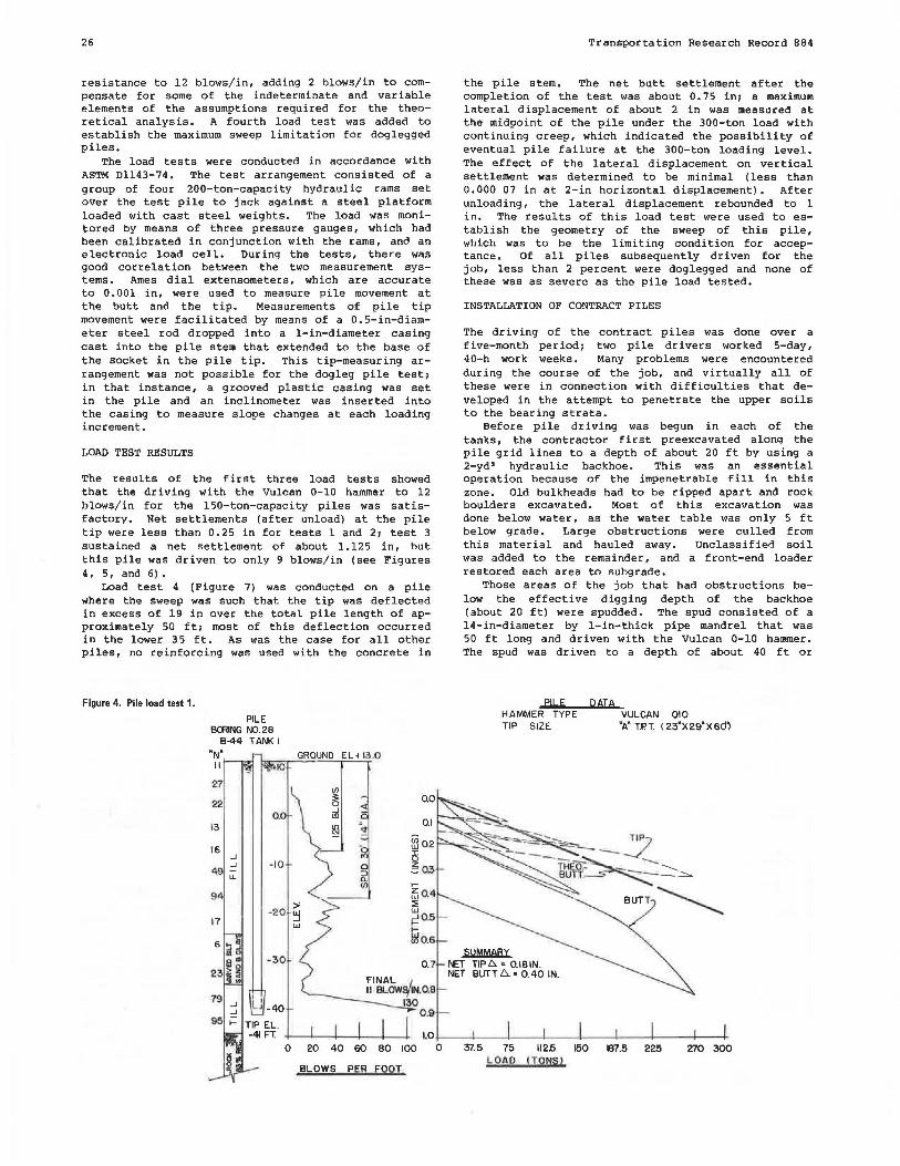
The results of the first three load tests showed that the driving with the Vulcan 0-10 hammer to 12 blows/in for the 150-ton-capacity piles was satisfactory. Net settlements (after unload) at the pile tip were less than 0.25 in for tests 1 and 2; test 3 sustained a net settlement of about 1.125 in, but this pile was driven to only 9 blows/in (see Figures 4,5,and6).
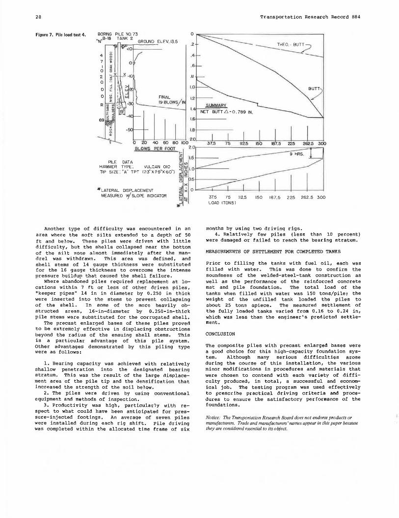
Load test 4 (Figure 7) was conducted on a pile where the sweep was such that the tip was deflected in excess of 19 in over the total pile length of approximately 50 ft; most of this deflection occurred in the lower 35 ft. As was the case for all other piles, no reinforcing was used with the concrete in
Figure 4. Pile load test 1.
PILE BOOING N0.28
B-44 TANK I
2.7
22
13
16 _J _J -10
~ ll.
9
-20 17
-30
UJ
~ 0.0 _J ID
0.1
~0.2 5 ~03 I-
/504 :::;: w ~0.5
mo.6
0.7
Transportation Research Record 884
the pile stem. The net butt settlement after the completion of the test was about 0.75 in; a maximum lateral displacement of about 2 in was measured at the midpoint of the pile under the 300-ton load with continuing creep, which indicated the possibility of eventual pile failure at the 300-ton loading level. The effect of the lateral displacement on vertical settlement was determined to be minimal (less than 0.000 07 in at 2-in horizontal displacement). After unloading, the lateral displacement rebounded to 1 in. The results of this load test were used to establish the geometry of the sweep of this pile, which was to be the limiting condition for acceptance. Of all piles subsequently driven for the job, less than 2 percent were doglegged and none of these was as severe as the pile load tested.
INSTALLATION OF CONTRACT PILES
The driving of the contract piles was done over a five-month period; two pile drivers worked 5-day, 40-h work weeks. Many problems were encountered during the course of the job, and virtually all of these were in connection with difficulties that developed in the attempt to penetrate the upper soils to the bearing strata.
Before pile driving was begun in each of the tanks, the contractor first preexcavated alonq the pile grid lines to a depth of about 20 ft by using a 2-yd' hydraulic backhoe. This was an essential operation because of the impenetrable fill in this zone. Old bulkheads had to be ripped apart and rock boulders excavated. Most of this excavation was done below water, as the water table was only 5 ft below grade. Large obstructions were culled from this material and hauled away. Unclassified soil was added to the remainder, and a front-end loader restored each area to subgrade.
Those areas of the job that had obstructions below the effective digging depth of the backhoe (about 20 ft) were spudded. The spud consisted of a 14-in-diameter by 1-in-thick pipe mandrel that was 50 ft long and driven with the Vulcan 0-10 hammer. The spud was driven to a depth of about 40 ft or
PILE
HAMMER TYPE TIP SIZE
SUMMARY !'ET TIP6. • 0.181N. NET BUTT 6.. • 0.40 IN.
QAIA VULCAN 010 "A" T.P.T. ( 23'X29"X6di
l.0+---+---+---1----+---+---+----t---+ 0 20 40 60 80 100 0 37.5 75 112.5 150 187.5 225 270 300
LOAD CTONSI BLOWS PER FOOT

Transportation Research Record 884
Figure 5. Pile load test 2. BORING PILE NO 87 B 24 TANK 3
GROUND EL.13,5
42 . -' 19 :;: -'
i ~
7
3 0.0 <i 15
CJ) ·~ 38
~ ~ g 0
10 6 m <:t !i -10
"' 0 R ~ CJ)
::::> -' <l.
-' CJ)
2 ;;;
0.
FINAL 0 12 BLOWS IN
I.I 0 20 40 60 80 100
Figure 6. Pile load test 3.
PILE N0.65
BLOWS PER
TANK-4 GROUND ELEV. 13.5'
FOOT
27
..eu_~ DATA HAMMER .<irn""PE.,..'.~_......._.....,VULCAN 010 TIP SIZE " "A" TPT f23" X 29' X 60" l
-.,.._ --- ....... -::._-..:.::::::_.,.._ Tl? -- ----------~2:-.::.:__--:_~
. THEO.- BUT~
BUTT
0 37.5 75 112.5 150 187.5 225 2625 300
LOAD !TONS)
PILE PATA HAMME"R TYPE : VULCAN 010 TIP S IZE : "A" TPT (23"X29"X60")
PER FOOT ~41-~--1~~-1-~~-1-~~-+-~~+-~~1--~--1~~-1-
0
less when the driving resistance indicated that the obstructed zone was penetrated. This was an effective procedure. Old cribbing and timbers were split and medium-sized obstructions were broken up or dislodged, thereby making it possible to penetrate the obstructed zones with the piles. There were some locations that were abandoned, and these piles were relocated to avoid the obstructions. The specif ications required piles to be driven within 12 in of plan location; when piles were relocated, the concrete mat was redesigned as required.
Driving difficulties developed in areas of the site that had intermediate zones of dense sand above the varved silts and clays that had to be penetrated. A wet-rotary-drilling system was attempted, but without success, because of the character of the
37.5 75 112 5 150 187.5 225 262.5 300 L OAD ITONSl
overlying fill. Therefore, it was necessary to hard-drive through the dense soil, and driving resistances of 600-1200 blows/ft were sometimes necessary to penetrate this zone. Once the pile tips were advanced below this layer, driving resistance abated and the piles successfully reached the intended bearing soils.
One localized area existed at the westerly side of tank 6 where the intermediate sand stratum was too dense to be penetrated by the enlarged base piles. In this area, approximately 15- to 100-toncapacity pipe piles, which were 14 in in diameter by 0.375 in thick, were substituted in accordance with criteria that had been established for a nearby liquefied" natural gas tank foundation.
28
Figure 7. Pile load test 4. BORING PILE NO. 73
"N"B- tS TANK 2 GROUND ELEV. 13.5
.101------
0
FINAL l2 19 BLOWS/IN
l4
1.6
1.8
0 20 40 60 80 100 2.0
~t..QWS PER FOOT 2 .0 I-z 1,5
PILE DATA ~(I) HAMMER TYPE: VULCAN 010 uw 1.0 TIP SIZE: "A" TPT (23" X 29"X 60") <t :i:
~~ 5
JtLATERAL ...Jx
DISPLACEMENT <t • a: x
MEASURED w/ SLOPE INDICATOR UJ
~!a 1F'
Another type of difficulty was encountered in an area where the soft silts extended to a depth of 50 ft and below. These piles were driven with little difficulty, but the shells collapsed near the bottom of the silt zone almost immediately after the mandrel was withdrawn. This area was defined, and shell stems of 14 gauge thickness were substituted for the 16 gauge thickness to overcome the intense pressure buildup that caused the shell failure.
Where abandoned piles required replacement at locations within 7 ft or less of other driven piles, "keeper pipes" 14 in in diameter by 0.250 in thick were inserted into the stems to prevent collapsing of the shell. In some of the more heavily obstructed areas, 16-in-diameter by 0.250-in-thick pile stems were substituted for the corrugated shell.
The precast enlarged bases of these piles proved to be extremely effective in displacing obstructions beyond the radius of the ensuing shell stems. This is a particular advantage of this pile system. Other advantages demonstrated by this piling type were as follows:
1. Bearing capacity was achieved with relatively shallow penetration into the designated bearing stratum. This was the result of the large displacement area of the pile tip and the densif ication that increased the strength of the soil below.
2. The piles were driven by using conventional equipment and methods of inspection.
3. Productivity was high, particularly with respect to what could have been anticipated for pressure-injected footings. An average of seven piles were installed during each rig shift. Pile driving was completed within the allocated time frame of six
Transportation Research Record 884
~!.lhlM8BY NET BUTT 6 = 0. 789 IN.
I I I 37.5 75 112.5 150 300
37.5 75 112.5 150 187.5 225 262.5 300 LOAD (TQNSI
months by using two driving rigs. 4. Relatively few piles (less than 10 percent)
were damaged or failed to reach the bearing stratum.
MEASUREMENTS OF SETTLEMENT FOR COMPLETED TANKS
Prior to filling the tanks with fuel oil, each was filled with water. This was done to confirm the soundness of the welded-steel-tank construction as well as the performance of the reinforced concrete mat and pile foundation. The total load of the tanks when filled with water was 150 tons/pilei the weight of the unfilled tank loaded the piles to about 25 tons apiece. The measured settlement of the fully loaded tanks varied from O .16 to 0. 24 in, which was less than the engineer's predicted settlement.
CONCLUSION
The composite piles with precast enlarged bases were a good choice for this high-capacity foundation system. Although many serious difficulties arose during the course of this installation, the various minor modifications in procedures and materials that were chosen to contend with each variety of difficulty produced, in total, a successful and economical job. The testing program was used effec;:tively to prescribe practical driving criteria and procedures to ensure the satisfactory performance of the foundations.
Notice: The Transportation Research Board does not endorse products or manufacturers. Trade and manufacturers' names appear in this paper because they are considered essential to its object.