composite structures: the first 100 · pdf file16 th international conference on composite...
TRANSCRIPT

16TH INTERNATIONAL CONFERENCE ON COMPOSITE MATERIALS
1
COMPOSITE STRUCTURES: THE FIRST 100 YEARS
William G. Roeseler, Branko Sarh, Max U. Kismarton
The Boeing Company
Keywords: Composite; Non-metallic; Fiberglass; Carbon reinforced plastic; Aerospace structures
Abstract
The history of composite structures since 1940
is reviewed in terms of structural performance,
tonnage, and value. Composites are here defined as
fiberglass and carbon reinforced plastic, although
other types of composite structures are briefly
treated. Examples are provided from aerospace,
marine, and construction industries along with
competitive metal performance. Based on current
trends, projections are made for future development
of composites in aerospace and other industries.
Introduction
The century between 1940 and 2040 is perhaps the most significant for composite structure, as composites are replacing metal for most aircraft applications, and billions of tons of lower cost composite structure are being used in marine, construction, and wind energy industries. Thousands of years ago, our ancestors used basic natural resources to make simple composites, using materials like mud and straw to fabricate shelter. Straw is a fibrous material with good properties when under tension, and dry mud has good compression load behavior. When embedding straw into mud, and drying/curing the mixture for a certain time, and possibly at elevated temperatures, a composite material with good tension and compression characteristics emerges. Principles of combining fibrous material with good tension stress values and matrix material with good compression load carrying capabilities provides engineers with design and manufacturing flexibility. Combining solid fibrous material and fluid or paste like material (matrix) allows fabrication of a variety of shapes, even complex ones, with very little effort. The only thing needed is a form (tool) to stabilize the material mix during the drying/curing cycle. Modern composites use high-strength, stiff fibers for both compression and tension, using the matrix only to support the fibers against buckling as the fibers carry the compression loads.
Basic principles of working with composite materials have not changed in centuries. House building using composites made of mud and straw
changed in the industrial age to steel and concrete composites for building high-rise buildings and civil engineering projects. What has changed are characteristics and mechanical properties of basic constituent materials. Thus, the evolution of today’s high-performance fibers like carbon or boron, embedded into a thermoplastic or thermoset matrix like epoxy, polyester, Nylon, etc. can be summarized as:
There are now many applications of composites in the aircraft and space industry. Manufacturing techniques that produce composite parts for the aviation industry have progressed from purely manual fabrication to highly automated processes using computer controlled machinery for laying up (layer-by-layer) prepreg material. This can be clearly seen by comparing the photographs shown below in Figure 1.
Fig. 1. Composites then and now
• Two or more materials combine to perform a useful purpose
• Exhibits the best properties of the individual materials plus
added qualities that the individual materials do not exhibit alone
• Examples
• Mud and straw
• Steel reinforced concrete
• Fibers embedded in plastic resin matrix
• Oriented Strand Board (OSB)

WILLIAM G. ROESELER
2
Higher Specific Strength and Stiffness
Composite structure in this context is defined as structures made up of fibers and resins, such as fiberglass, carbon, boron, Kevlar, or Spectra in a matrix such as epoxy, vinyl ester, bismaleimide, polyimide, or polyester. Monolithic metal structures are used for comparison, and lower cost composites such as wood, foam cores and reinforced concrete, are also included.
In aircraft and space product applications, the weight of structures is a critical parameter in determining performance. The need for lowest possible structural weight led to development of high performance composites using carbon fibers and epoxy resins.
The advantages of composite materials as compared to metal become obvious when comparing specific strength and stiffness of high-performance fibers with that of conventional isotropic aircraft materials like aluminum, titanium, and steel. The data shown in Figure 2 indicate a clear advantage of high-strength fibers compared to popular aircraft metals. In addition, the galvanic corrosion problems (prevalent with aluminum alloys) are avoided and fatigue of metallic structures (necessitating high inspection and maintenance costs), are of less concern with composite materials. Of course, combining aluminum with carbon can lead to severe corrosion of the aluminum unless the electrolyte is kept out of the joints.
Fig. 2. Properties of high strength fibers
Prediction Regarding Future Aircraft
The artist concept in Figure 3 and the following quote from a Popular Mechanics article in 1943 foretold the jumbo (B747/A380) transports of today, which were made possible by continuing advances in materials and processes. “Airplanes weighing as much as one and one-third million
pounds are deemed possible by H. D. Hoekstra of the Civil Aeronautics Administration, who believes that one of the main limiting factors at present is the development of large-enough power plants. Although aluminum alloy may not lose its leadership as a structural material, Mr. Hoekstra cites research now under way in glass and plastics that might result in a product which could take its place, particularly if the glass fibers can be combined into a usable material with plastics as a bonding agent. Stainless steel also is a contender, and may always be essential at points involving corrosive effects and where spot welding would reduce weight.”
Fiberglass Primary Structure
The first major application of advanced
composites to aircraft was the fiberglass rotor technology and homebuilt aircraft of the 1960s. Some of the pioneering work was done in 1965 at the Aeronautical Research & Development Corp. in Cambridge, Mass., where uni-glass rotors and main landing gear, and a fuselage of thin fiberglass skin were built for the Autocopter, an early flying automobile. Boeing, McDonnell, and other rotorcraft companies were quick to recognize the advantages of composite rotor structure. Figure 4 shows one of the large helicopters that incorporated this technology during the 1970s. The life-limited main rotor blades of early Chinook helicopters were metal, and required frequent inspections to maintain airworthiness.
Fig. 3. Concept of jumbo transport

3
COMPOSITE STRUCTURES: THE FIRST 100 YEARS
Fig. 4. 1980 composite primary structure
When composites were incorporated on these large transport helicopters in the 1980s, customers enjoyed not only better performance, but the cost of maintaining the safe-life main rotor structure was substantially reduced. Another benefit of the composite (mostly fiberglass) rotor blades was greatly improved damage tolerance with respect to the various ballistic threats encountered by this type of transport aircraft.
Global Composite Industry
Railway composites are examples of popular combinations of wood and steel, with at least 100,000 miles of such construction still in service since 1940. If the rails weigh 100 lbs. per foot and the creosote treated ties are approximately equal weight, that would add 5000 x 100,000 x 200 = 1E11 lbs. Barbed wire and other fences still in use across the prairie might add another 1E11 lbs. in this country, perhaps 1E12 lbs. in the world. Railways and fences typically cost less than $1 per lb., so their total value is on the order of $1E12.
There are about a billion acres of forest land in North America, about the same in South America, Europe, Asia, and Africa. For every ton of wood grown, a young forest produces 1.07 tons of oxygen and absorbs 1.47 tons of CO2. Wood represents 47% of US industrial production, compared to 23% for steel and 2% for aluminum, but the energy use for wood is only 4%, compared to 48% for steel and 8% for aluminum. Figure 5 shows industrial production of selected raw materials during the first 100 years of composites. Wood tonnage is roughly twice that of steel during this time span with concrete tonnage greater than that of wood.
Global usage of fiber reinforced plastic is growing rapidly, but is still a lot less than the other, popular materials.
0
2
4
6
8
10
12
1940 1950 1960 1970 1980 1990 2000 2010 2020 2030 2040
Year
Log Tons
Steel
Aluminum
Carbon
Global steel currently a billion tons per year
0
2
4
6
8
10
12
1940 1950 1960 1970 1980 1990 2000 2010 2020 2030 2040
Year
Log Tons
Steel
Aluminum
Carbon
Global steel currently a billion tons per year
0
2
4
6
8
10
12
1940 1950 1960 1970 1980 1990 2000 2010 2020 2030 2040
Year
Log Tons
0
2
4
6
8
10
12
1940 1950 1960 1970 1980 1990 2000 2010 2020 2030 2040
Year
Log Tons
Steel
Aluminum
Carbon
Global steel currently a billion tons per year
Fig. 5. Carbon compared to popular materials
Global Value During the Century
Figure 6 shows the total value and tonnage of popular materials during the past 100 years.
Mass and Value
0
2
4
6
8
10
12
14
16
0 2 4 6 8 10 12 14 16
Log Mass (pounds)
Log Value (2007 US Dollars)
Concrete
$1/lb
$1000/lb
WoodMarine
UAV
AircraftWind
Steel
Fig. 6. Global value in various industries
Steel reinforced concrete has been the most popular composite in terms of tonnage. The interstate highway system in the USA consists of over 50,000 miles of four-lane roadway, mostly steel reinforced concrete, about 100 feet wide and one foot thick. This amounts to 50,000 x 5000 x 100/27 = 1E9 cubic yards worth about $1E11 and weighing over 5E12 lbs. The 1000 major airports in the world each have at least one runway, 10,000 x 100 x 1 ft. thick. Airport runways add 1E3 x 1E6 = 1E9 cubic feet = 1E11 lbs worth about $1E11. A typical residential driveway or foundation in this country requires roughly 100 cubic yards, 300 tons, of reinforced concrete. If there were 1E8 such homes built during the century, a billion such homes in the world, that would add 3E11 tons worth $1E13. The concrete is worth $1E13, and the homes are worth at least $1E14. The Sears Tower in Chicago and thousands of other industrial buildings around the world add lots of tonnage and value, but are probably not yet as significant as a billion homes.
According to the International Monetary Fund, the gross domestic product today is $44E12, with

WILLIAM G. ROESELER
4
$14E12 in the European Union, $12E12 in the United States, and $5E12 in Japan. By 2040, this will grow to $1E4 x 1E10 = $1E14. Hence the global economy for the century is around $1E15. The automotive industry produces 1E8 vehicles each year, average cost $1E4, for a total value of $1E12. These are 90% steel below $10/lb. There are 6E8 cars on the roads today, about one ton each, costing $1E4. That’s roughly a billion tons of steel worth well over $1T, about one year’s production of steel.
The Importance of Damage Tolerance
Whenever progress is made in materials and structures, we worry if the new materials and processes will improve the safety of the industry. This is especially true of aerospace, where lives depend on adequate levels of damage tolerance being maintained. At the dawn of the Jet Age, the industry was just learning to build commercial jet aircraft, and lives were lost due to miscalculations in damage tolerance on the pressurized fuselage of the Comet, shown in Figure 7. Fatigue cracks grew and became critical during normal operation, and the fuselage opened up due to cabin pressure loading, destroying the structural integrity of the aircraft.
Fig. 7. The Comet (first jet transport) and early military jets underscored the importance of damage tolerance
Pressure Vessels
As an industry, we learned during the 1950s that large, thin walled pressure vessels cannot work safely anywhere near their ultimate hoop strength. We also learned in 1960 that wing compression material can’t reliably be worked near its yield strength. We tried working 80 ksi aluminum to 70 ksi at ultimate load, 28 ksi compressive fatigue load, and we had to repair lots of early fatigue cracks.
Early pressure vessels were built of welded or riveted steel to leak before fail criteria, which limited hoop stresses below 10 ksi at operating load, 30 ksi at ultimate load. The specific strength was 30/.3 = 100 ksi/pci. As pressurized cabins became popular in commercial aircraft after 1950, early jets tried to
exploit the weight advantages of high strength aluminum alloys. The Comet was designed for hoop stress of 20 ksi at one factor cabin pressure of 6 psi. It was tested to two factor ultimate 40 ksi @ 12 psi, but failed to provide adequate levels of damage tolerance with respect to fatigue cracks, which started at the corners of several openings that had high stress concentrations due to their shape. Following the tension failures of 1954 and 1956, hoop stresses on the 707 and all subsequent commercial aircraft were maintained below 16 ksi. This resulted in a level of tension performance around 32/.1 = 320 ksi/pci, about three times higher than the boiler codes.
Mistakes were also made on Boeing airplanes as aluminum was pushed to higher and higher yield strength to get weight out of the structure in an effort to increase range of the aircraft.
Industry experts have been meeting since 1960, especially since 1980, to spread understanding of durability and damage tolerance of composites. NASA has had a role since 1975 in promoting industry sharing on this subject. The first carbon/epoxy primary structure was put into service on the 737 horizontal tail in 1984 and on the DC-10 vertical tail in 1987 as a result of this government sharing.
Some aluminum and composite history is shown in Figure 8. It traces specific strength improvements past the tension failure of 1955 and the costly compression failures circa 1960. The huge potential of composite structure is clearly shown by the rotorcraft, UAV, and wing turbine data, although the specific strength improvements on carbon, transport aircraft structures have been limited since 1980 due to real and perceived damage tolerance issues. Units are thousands of pounds per square inch (ksi) normalized by density in pounds/cubic inch (pci). In SI units, strength of 100 ksi = 690 MPa, and density of 0.1 pci = specific gravity of 2.9. Hence, ultra high strength (100 ksi) aluminum would show up as 100 ksi/.1 pci = 1000 ksi/pci = 690 MPa/2.9 = 238 MPa.
500
550
600
650
700
750
800
850
900
1930 1950 1970 1990 2010 2030 2050
Specific Strength Stress / Density
(Ksi / pci)
Year
DC-3DC-7
B-47
B-52
Comet
737747
757767
IACC
Military
Helicopters
Wind Energy
CommercialWings
777-wing
CommercialTailsSpruce
Goose
UAVs
7055
23242224
7150
7075
2024
Metallics
Composites
Fig. 8. Specific strength of wing bending material
5
COMPOSITE STRUCTURES: THE FIRST 100 YEARS
Figure 9, taken from a 1995 report by Bob Davis and used by Phil Condit (5) at the first World Aviation Congress at Los Angeles International Airport in 1996, shows recent improvements with the various aluminum alloy families and their uses on Boeing airplanes. Fundamental understanding of chemistry relationships and related effects on mechanical and fracture properties have been the backbone of technology advances in this area.
150
FractureToughnessKaap,Ksi √ in
40 60 80 100
200
100
50
0
Lower Wing• 767• 757• 737• 747-400• 777
Upper Wing• 767• 757• 737-300-400, -500
• 747-400
• 777 Fuselage
2XXX-T3
7150
Upper Wing• 737-700,-800• 7777055
7075-T651
2024-T3
2024-T351
Old Technology
7178-T651
7150
2324-T392224
Goodness
• 777 Body Stringers
Typical Yield Strength, Ksi
150
FractureToughnessKaap,Ksi √ in
40 60 80 100
200
100
50
0
Lower Wing• 767• 757• 737• 747-400• 777
Upper Wing• 767• 757• 737-300-400, -500
• 747-400
• 777 Fuselage
2XXX-T3
7150
Upper Wing• 737-700,-800• 7777055
7075-T651
2024-T3
2024-T351
Old Technology
7178-T651
71507150
2324-T392224
Goodness
• 777 Body Stringers
Typical Yield Strength, Ksi
Fig. 9. Boeing structural aluminum alloy improvements
Composites versus Aluminum
The use of carbon/epoxy for primary wing structure was explored in 1980 on a NASA contract (2) Large Composite Primary Aircraft Structure (LCPAS), about the same time it was put into production on several military wings.
Test results and conclusions were as summarized in Figure 10. Although the blade stiffened panel worked to 52 ksi as a short column with no local pressure, the demands of combined loads and residual strength favor a discrete stiffener with a substantial bending capability, as provided by the I or J concepts. Because 1980 tooling and assembly techniques favored the I over the J concept, the I concept was selected for the final LCPAS sizing.
LCPAS 1982 (2220-3)Rhodes and Williams 1981 (5208)Aluminum (7150)Impact damage ½ in. –diameter metal impactor
Normalized Gross Failure Stress (Ksi)
5 10 15 20 25 30 20 30 40 50 60
XXX
X
XX X
XXX
End load Nx (Kip/in.) Shear Stiffness Ratio Gt/Nx
20
30
40
50
60
70
10
11-511-5
1B-11J-3
3B-3
27%
Mass Reduction
8%
3J-1
3I-1
3B-3
3B-33J-13I-1
1990 Compression Allowable Target
1980 Alum
inum
(Norm
alized to
G/E D
ensity)
X
LCPAS 1982 (2220-3)Rhodes and Williams 1981 (5208)Aluminum (7150)Impact damage ½ in. –diameter metal impactor
Normalized Gross Failure Stress (Ksi)
5 10 15 20 25 30 20 30 40 50 60
XXX
X
XX X
XXX
End load Nx (Kip/in.) Shear Stiffness Ratio Gt/Nx
20
30
40
50
60
70
10
11-511-5
1B-11J-3
3B-3
27%
Mass Reduction
8%
3J-1
3I-1
3B-3
3B-33J-13I-1
1990 Compression Allowable Target
1980 Alum
inum
(Norm
alized to
G/E D
ensity)
X
Fig. 10. LCPAS compression panel test summary
Similar stiffeners were also used on the first carbon tail for the 737 about the same time, and on at least one military transport.
Figure 11 depicts typical wing structure proposed during the LCPAS contract to replace metal wings on a 767 type commercial transport. The wing torsional stiffness was maintained by enforcing Gt/Nx, panel shear stiffness. We relied on embedded planks instead of toughened resins or stitching to provide damage tolerance. Later wing panels relied on fastening or stitching along with toughened resin to provide adequate levels of damage tolerance with respect to hail impact damage, engine burst, and the various other threats to be considered for commercial aircraft.
Component
TheoreticalMass
Reduction (%)
Upper Surface
Lower Surface
Spars
Total
(Panels + Spars)
24
49
40
38
Component
TheoreticalMass
Reduction (%)
Upper Surface
Lower Surface
Spars
Total
(Panels + Spars)
24
49
40
38
Component
TheoreticalMass
Reduction (%)
Upper Surface
Lower Surface
Spars
Total
(Panels + Spars)
24
49
40
38
Component
TheoreticalMass
Reduction (%)
Upper Surface
Lower Surface
Spars
Total
(Panels + Spars)
24
49
40
38
Component
TheoreticalMass
Reduction (%)
Upper Surface
Lower Surface
Spars
Total
(Panels + Spars)
24
49
40
38
Component
TheoreticalMass
Reduction (%)
Upper Surface
Lower Surface
Spars
Total
(Panels + Spars)
24
49
40
38
Fig. 11. LCPAS wing sizing based on test results
Wind Energy
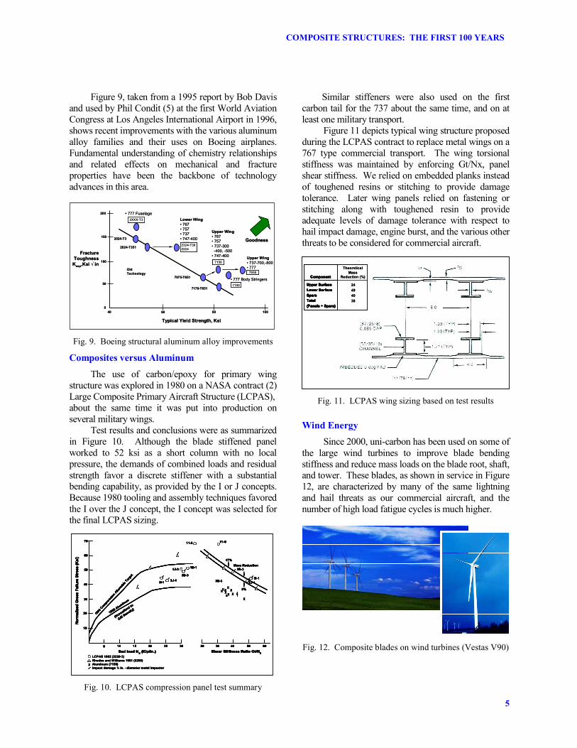
Since 2000, uni-carbon has been used on some of the large wind turbines to improve blade bending stiffness and reduce mass loads on the blade root, shaft, and tower. These blades, as shown in service in Figure 12, are characterized by many of the same lightning and hail threats as our commercial aircraft, and the number of high load fatigue cycles is much higher.
Fig. 12. Composite blades on wind turbines (Vestas V90)

WILLIAM G. ROESELER
6
By the time we have two million pounds of high performance commercial composite wing structure in service in 2010, there will already be 2 billion pounds of high performance wind turbine blades in service generating over 20 gigawatts of power around the world. Some of the composite blades have strain sensing networks to maintain safety in the harsh environment. Bonded repairs are a way of life in wind energy. Many valuable lessons can be learned in this large scale composites laboratory.
Marine Composites
In 2006, advanced carbonology and fiber optic strain sensors were used on the free standing carbon spars for the Maltese Falcon, the latest sailing yacht, shown in Figure 13. Each of the three main spars stands 200 feet tall and carries 150 million inch pounds of ultimate bending moment at deck level, where the load is invested in a two inch thick bending section that is only four feet in diameter. Each of the three sails on the Maltese Falcon carries more sail area than the entire wing on a 747 or A-380 jumbo jet. This magnificent yacht is but the latest in a series of millions of boats built mostly of composites during the first hundred years. The hull happens to be steel, but there are many others, including the still larger Mirabella V, built entirely of composites. Reference 4 gives a 1996 update on the case for commercial sail craft, which is another phase of structural composites that may figure prominently in the next 25 years. Some of the commercial sail craft in service since 1982 are larger and heavier than the Maltese Falcon. Tonnage of composite materials used in boat building has far exceeded aerospace usage, and this trend will likely continue through 2040. There are many valuable lessons to be learned from these remarkable, composite structures.
Fig. 13. Composites at sea with the Maltese Falcon
Global View - Composite Structural Performance
Figure 14 shows how improvements in structural efficiency since Howard Hughes’ Spruce Goose circa 1940 could lead to a space elevator a century later. Since 1940, aerospace composites have grown in importance, thanks to the high strength-to-weight ratio of many modern fibers including glass, boron, carbon, Kevlar, Spectra, Vectran, and Silicon Carbide. Figure 14 also shows typical properties for several metals and composites which have become popular. Currently, the best carbon fibers have an ultimate tensile strength of about a million pounds per square inch (psi).
Specific Strength, Log (ksi/pci)
Year
Uni - Laminates
Zylon, dry
Vectran, dry
Oil Drilling
AL-7050
Wind Energy
Quasi - Laminate
s
Metals
Uni, Rod
Spectra lines
GR fiber, dry
Uni, Spring
DC-3
B-52
767 777
AL ladders
Chop
Fiber
747
4130
Corvette
787
B-47
DC-7
Autocopter
Nano
Fibers
Comet
1940 1950 1960 1970 1980 1990 2000 2010 2020 2030 2040
AL Ti Steel Wood Plastic Glass CFRP
AL-7150
High Pressure Tanks
Fig. 14. Improvement in specific strength during the first
100 years of composites
Uni-composites are limited to around 400,000 pounds per square inch, and isotropic composites typically test below 100,000 psi. Million psi carbon fiber and 500,000 psi Spectra are already providing levels of tension performance that is an order of magnitude higher than the best materials available in 1940. Pultruded, unidirectional carbon rods and the filament wound, uni-carbon spring on the 767 are providing record levels of compression performance. The best metal products barely achieve the level of structural efficiency provided a hundred years ago by premium wood products for main wing spars, although the isotropic properties of metals make them much better for bolts and fittings.
World Record Performance
The highest performing compression flange on any commercial or military aircraft is the uni-carbon passenger entry door spring (1) on the 767, Figure 15. It began service on the 132nd airplane (~ 1984), and has now been installed on over 800 airplanes. Every time a flight attendant closes the door, this spring winds up to 100 ksi, tension on the outside and compression on the inside of the bending section. Ultimate strength of this remarkable filament wound product is 150 ksi.

7
COMPOSITE STRUCTURES: THE FIRST 100 YEARS
Fig. 15. 767 and entry door spring
Aerospace Composites
The early use of composite materials in the aircraft industry dates back to the late 1950s and started with aircraft like the 707 and later DC-9. Due to high safety standards, specifically in the commercial aircraft industry, implementation of composites occurred gradually over time in three phases. First, composite materials were used on tertiary composite components like interior parts, sidewalls, bag racks, and galleys. These parts would not cause any harm to the aircraft flying capabilities if the parts failed in operation. In the late 1960s, only after use of composites with interior parts proved successful, were composites introduced into secondary aircraft structures like spoilers, rudders, ailerons, and flaps. Carbon replaced fiberglass in most of these secondary structures in the 1970s, although fiberglass was retained for many interior parts and fairings. The most critical commercial aviation implementation of composite materials is with primary structures, like stabilizers, wings and fuselage barrels, and has occurred gradually over the last two decades.
The design and use of boron and carbon started with military aircraft and rapidly expanded from use on flight control surfaces (rudders, flaps) to stabilizers, wings and fuselage structures as exemplified by the AV-8B, B-2, F-18, Euro-fighter, and AH-66 data shown in Figure 16.
One of the first high-performance composite materials (for primary structures) was introduced in the 1980s on the 737 horizontal stabilizer and underwent extensive testing and in-flight evaluations. In the mid 1990s, composite vertical and horizontal stabilizers for the 777 were designed, developed, and implemented into production, reaping the benefits of lightweight structures and improved aircraft performance.
707 DC-9
767
737-300
DC-10L1011
MD-11747-400
7E7
A380
OV-22
A400M
A330-200F/A-18 E/F
F-22
F-35
ATR72
ATR42
1940 1960 1980 2000 2020
60
50
40
30
20
10
0
Boeing
Non-Boeing
757
B-2
Gripen
A310
LCA
Eurofighter
AV-8B
Percent of Composite in Airframe
AH-66
777A320
A340
Fig. 16. Growth of aerospace composite structures use
The new generation commercial aircraft, the 787 (Dreamliner), was designed almost entirely with high-performance carbon fiber materials including the stabilizers, wings, and fuselage, which represents 50% of aircraft structural weight. Increased use of composite materials on military and commercial aircraft is here to stay.
Validation of Composite Structures
To validate composite materials’ performance and verify structural integrity, numerous tests must be performed before a new aircraft can obtain FAA certification. The typical progression is depicted in Figure 17. First, basic material characterizations are carried out at a coupon level, to determine the safe tension, compression, and shear stress that the composite material can carry before failing. Next, structural elements are tested under typical operational load conditions to evaluate buckling and other behaviors. Verifying fatigue life of structural joints involves another round of static and fatigue testing to demonstrate quality of assembly processes and structural interfaces. The majority of fasteners are titanium and Inconel instead of aluminum, to improve durability and corrosion resistance of the structures.
• Proven Certification process, validated by positive service experience
•Boeing design objectives typically exceed minimum regulatory requirements
Assemblies
ElementsMaterialSpecimens
Components
Static TestFatigue TestGround & Flight Tests
Airplane
Increasing Levels of Complexity
• Proven Certification process, validated by positive service experience
•Boeing design objectives typically exceed minimum regulatory requirements
Assemblies
ElementsMaterialSpecimens
Components
Static TestFatigue TestGround & Flight Tests
Airplane
Increasing Levels of Complexity
Fig. 17. Analysis/testing ensures safety and reliability

WILLIAM G. ROESELER
8
Major components like the fuselage, main wing box, and stabilizers, must also undergo extensive testing under “in-flight" conditions in the lab, which includes applying maximum static and dynamic loads, simulating in-flight conditions. These structural tests are designed to prove that airframe composite structures can safely sustain all regulatory loads without failure and at least two operational lifetimes. While structural component tests are still underway, ground and flight testing with the first aircraft commences. The objective is to validate aircraft performance in flight under normal and extreme conditions. After all tests are satisfactorily completed, validating the very rigorous analysis, a new aircraft can then obtain FAA certification for commercial passenger operations. The first flight of the 787 Dreamliner is scheduled during the last half of 2007.
Boeing Composite Usage
Increased use of composites and declining use of metal over time on major Boeing commercial aircraft is illustrated in Figure 18.
CompositeSteelTitaniumAluminumMiscellaneous
Increa
sed us
age ov
er time
Materials
1%747
3%757/767
11%777 50%
787
CompositeSteelTitaniumAluminumMiscellaneous
CompositeSteelTitaniumAluminumMiscellaneous
Increa
sed us
age ov
er time
Materials
1%747
3%757/767
11%777 50%
787
Fig. 18. Increased use of composites over time
The total weight of composite materials on the early 747 aircraft was only about 1% of the structural weight, although there was a substantial amount of fiberglass sandwich in secondary structural applications. This aircraft was made predominately from aluminum alloys, titanium and steel. The 757 and 767 aircraft designs expanded the use of composites to approximately 3% of aircraft structural weight (mainly due to carbon sandwich flight control components). With additional introduction of composite primary structure, like the 777 empennage and floor beams, the portion of composite structural weight rose to 11%. The most progressive commercial aviation composite structures today are the 787 primary structures (wings, fuselage, and stabilizers), as
well as all secondary flight control components, now accounting for ~ 50% of the total aircraft structural weight. Aluminum alloys will make up only about 20% and titanium about 15% of the total 787 structural weight.
787 Dreamliner
As shown in Figure 19, a variety of composite structural design configurations and composite fabrication methods is being used for 787 primary and secondary structures. All fuselage sections and the main wing box are designed with carbon fiber epoxy laminates as well as the horizontal and vertical stabilizer boxes. Wing leading edge slats and trailing edge flaps are also made of carbon fiber laminate materials. Secondary structures (rudder, elevators, winglets, and nacelle cowlings) feature carbon sandwich construction. Several fairings on the wing, stabilizers, radome, and wing-to-fuselage fairings are made of other composites like glass fiber epoxy and similar materials. Metal alloys have a very useful purpose on the leading edges of nacelles, serving as a good heat conductor for thermal anti icing. Titanium is also used for some joints and internal substructures like heavy load carrying fittings and for most landing gear components.
Composites50%
Aluminum20%
Titanium15%
Steel10%
Other5%
Carbon laminate
Carbon sandwich
Other composites
Aluminum
Titanium
Titanium/steel/aluminum
Carbon laminate
Carbon sandwich
Other composites
Aluminum
Titanium
Titanium/steel/aluminum
Composites50%
Aluminum20%
Titanium15%
Steel10%
Other5%
Carbon laminate
Carbon sandwich
Other composites
Aluminum
Titanium
Titanium/steel/aluminum
Carbon laminate
Carbon sandwich
Other composites
Aluminum
Titanium
Titanium/steel/aluminum
Fig. 19. Composite solutions applied throughout the 787
Future Transportation Markets
The use of composite materials will enjoy expanded applications and growing importance, specifically in the transportation industry, facilitating development of innovative vehicle designs. One example of such innovation may be in the development of dual-mode vehicles for door-to-door transportation.

9
COMPOSITE STRUCTURES: THE FIRST 100 YEARS
These vehicles, also called flying cars, will be capable of operating on the ground at freeway speeds and flying at general aviation aircraft speeds. As noted previously, some of the pioneering work on aviation composites was done in 1965 in Cambridge, Mass., on the Autocopter, which was built and ground tested, but never actually flew. Many other composite rotorcraft and general aviation aircraft have been developed since then, clearly demonstrating the maturity of composite airframe technology.
The owner of an Advanced Flying Automobile (AFA) will be able to drive from the garage to an airport, and once at the airport, flight components (which are stored inside the vehicle) will be automatically deployed by the push of a button, converting the automobile into an aircraft, ready for flight to the next airport. After landing, all flight components will be retracted into the body, and the traveler will immediately drive to the final destination. This will enable travelers to reduce travel time significantly, which is the main motivation for creating and developing this type of vehicle.
The projected amount of travel time to be saved with a dual mode vehicle (as opposed to traveling only by car or by using a commercial aircraft), is depicted in Figure 20. For example, a destination of 400 miles would typically involve eight hours on the road using a car, six hours taking a commercial aircraft via a hub, or three and a half hours catching a direct flight (if available) with an airliner. Using an AFA, travelers will be able to get there in three and a half hours, much more conveniently than with the airlines and much faster than using an automobile.
��������
��������
����
(����) (����)(����) (����)
(����)
(����)
+
+
+
+
++
+
+
+
���� ����
(����) (����)+ +
���� ����
����
����������������
����
��������
����
12.0
11.0
10.0
9.0
8.0
7.0
6.0
5.0
4.0
3.0
2.0
1.0
Travel Time (Hours)
100 200 300 400 500 600 700 800
AutomobileCommercial AC Using HubCommercial ACAdvanced Flying Automobile
Flight Destination (Miles)
Automobile
Commercial w Hub
Commercial AC
AFA Flight Mode
AFA Driving Mode
��������
��������
����
(����) (����)(����) (����)
(����)
(����)
+
+
+
+
++
+
+
+
���� ����
(����) (����)+ +
���� ����
����
����������������
����
��������
����
12.0
11.0
10.0
9.0
8.0
7.0
6.0
5.0
4.0
3.0
2.0
1.0
Travel Time (Hours)
100 200 300 400 500 600 700 800
AutomobileCommercial AC Using HubCommercial ACAdvanced Flying Automobile
Flight Destination (Miles)
Automobile
Commercial w Hub
Commercial AC
AFA Flight Mode
AFA Driving Mode
Fig. 20. Diverse modes of transportation
Conclusion
We have shown some of the advantages of advanced composites over other materials in the context of worldwide usage during the first 100 years, 1940 to 2040. Although fiberglass and carbon/epoxy composites are not yet as important as wood, concrete, and steel in terms of tonnage or total revenue, they are very important in aerospace, transportation, and energy industries, especially for the new airplanes that will provide big improvements in fuel use, emissions, noise, and other environmental issues. We have discussed some of the damage tolerance issues that caused problems early in the Jet Age and have suggested means of assuring that similar problems do not reoccur as we move from metal to composites for our wings, bodies, tails, fuel tanks, airframes, and other critical structures. The future for composite materials and structures will be bright indeed, as we build on the millions of pounds of carbon aircraft structure already flying and the billions of pounds of related marine, wind energy, offshore oil, and other composite structures.
Figure 21 shows just three of the myriad of growing uses and applications of composite materials. It has become the preferred choice of innovative designers for the benefits it offers in structural efficiencies, durable products, and reduced life cycle costs, which make for satisfied customers and a win/win situation for materials suppliers and parts producers as well.
Fig. 21. In the sky, by sea or on land: the best is yet to come
The first trillion dollars in composite-based product revenues has already been banked, and there will be several more trillions of dollars worth of composite based aircraft, wind turbines, buildings, and other vehicles and products produced prior to 2040 – the end of the first 100 years of composites.

WILLIAM G. ROESELER
10
References
1. US Patent 4,765,602 Composite Coil Spring, William G. Roeseler, assigned to The Boeing Co, filed 22 Dec 1982, issued 23 Aug 1988.
2. McCarty, J. E., and Roeseler, W. G.;
Durability and Damage Tolerance of Large Composite Primary Aircraft Structure; NASA CR 3797; 1984.
3. Sarh, Branko; Advanced Manufacturing
Technologies for Composite Aircraft Structures Based on Prepreg Materials; 40th International SAMPE Symposium and Exhibition; Anaheim CA; 8-11 May 1995.
4. Roeseler, Schmidt, Beattie, Roeseler, Culp,
Long, McGeer, and Wallace; The Case for Transport Sail Craft; AIAA/SAE Paper 96-5611; World Aviation Congress, LAX, 1996.
5. Condit, P. M., Performance, Process, and
Value: Commercial Aircraft Design in the 21st Century, Wright Bros Lecture in Aeronautics, World Aviation Congress and Exposition, LAX, 1996.
6. Sarh, Branko, Lightweighting of Composite
Structures for Transportation Systems, workshop at EADS, Munich, Germany, 14 March 2003.
7. Renton, Olcott, Roeseler, Batzer, Baron, and
Velicki, Future of Flight Vehicle Structures (2002 – 2023), Journal of Aircraft, V 41, No 5, Sept-Oct 2004.
8. Sarh, Branko; Advanced Manufacturing for
Emerging Aircraft; University of Sheffield, Rotherham, UK, 10 May 2006.