comprehensive test plan 60%
TRANSCRIPT

1
COMPREHENSIVE TEST PLAN 60% DESIGN SUBMITTAL Florida Department of Transportation, District 1 Manatee County Automated Traffic Management System Phase 2 Manatee County, Florida FPID No. 42663515201 Federal Aid No. ARRA 149 B Contract No. E1H53 February 13, 2010 Prepared by:
8507 Benjamin Rd. Suite G Tampa, FL 33634 (813)249-9057

2
System Test Plan Table of Contents
Section Number Section Description 1.0 Configuration and Data Management
2.0 Policies
3.0 Configuration Identification
4.0 Change Control
5.0 Configuration Status Accounting
6.0 Configuration Database
Appendix B - Configuration and Bench Testing Forms
1. Device Cabinet 2. CCTV 3. MVDS 4. Ethernet Switch 5. Video Encoder 6. Wireless Radio 7. Uninterruptible Power Supply

3
Overview The Comprehensive Test Plan establishes methods necessary to verify that system end-items satisfy their requirements. The processes that lead up to this event and the data management and verification process are an integral part of this overall product and therefore are described herein. The test plan addresses verification requirements and criteria for solution alternatives; definition of verifications to demonstrate proof of concept; and development, qualification, acceptance and pertinent operational, and other testing.
Procedures for accepting all project field devices installed by the contractor are accomplished through the standard FDOT Construction Engineering Inspection effort.
1 Configuration and Data Management
1.1 Purpose and Scope This section provides an overview of the plan and procedures for managing the configuration of major ITS items under this project, reporting of configuration status, and audits. Bench testing of items may also be accomplished as part of these procedures. The scope of this document extends to the Configuration Items (CI) listed below.
1.2 Product and Configuration Items Device Cabinets CCTV Cameras MVDS Ethernet Switches Video Encoders Wireless Radios Uninterruptible Power Supplies (UPS)
1.3 CM Tools CM tools are those items utilized in performing the configuration management. These include, but are not limited to, databases, spreadsheets, manufacturer’s cut sheets, manufacturer’s specifications, FAT documentation, and test & measurement tools and utilities.
2 Policies 2.1 CM Activities
CM activities may be performed by Manufacturer, System Manager, and Contractor personnel depending on the level of configuration and which component will be configured. Policies specific to each component will be covered in a separate section or document detailing that device or component.

4
2.2 Organization, Responsibilities and Authorities of Interested Parties Parties involved in configuration include but are not limited to: Engineer, System Manager, Manufacturer, Supplier, Contractor and Sub-contractor. Specific authorities and responsibilities are detailed under Section 4: Change Control, but in general the System Manager will supervise configuration management completed by the Manufacturer, System Manager, and Contractor, with final approval by the Engineer.
2.3 Qualifications and Training Personnel involved in configuration of devices and components shall be trained and qualified in accordance with the applicable specification for that device or component.

5
3 Configuration Identification
3.1 Numbering Conventions Configuration documents shall be numbered in accordance with the following numbering scheme. [documentname] [version] [extension] Where the document name is specific to the device to be configured, the version is a whole number 1-infinity indicating how many versions have existed to date and a decimal number represents a minor change such as grammar, typos or similar. An unapproved version will carry the designation of draft until such time as the engineer shall approve it. Examples:
• First Draft – [documentname] draft • Subsequent drafts (unapproved submissions) - [documentname] draft
[version] • First approved version [documentname] 1.0 • Second version (unapproved) - [documentname] draft 2.0 • Second approved version with a minor typo corrected - [documentname]
2.1 3.2 Established Configuration Baselines
In most cases the manufacturer should provide documentation of a baseline (or factory default) configuration. When provided this configuration will be stored as the “Factory Baseline”. When a baseline is not supplied by the factory, then the configuration specified for this project shall be the baseline and noted as “Project Baseline”.
3.3 Use and Allocation of Serial Numbers or Other Traceable Identification Where devices have manufacturer serial numbers, that serial number shall be included in the configuration file. In the absence of serial numbers, the device or component shall be identified by its site specific designation in both the serial number and device ID fields of the configuration file.
3.4 Release Procedures for Product Configuration Information All requests for configuration data shall be received and processed by the system manager to ensure that the latest version is provided.

6
4 Change Control 4.1 Relationship of the Dispositioning Authority with Other Parties
Roles and responsibilities pertaining to changes to the configuration management data are outlined below.
Entity Role Information Flows to / from Dispositioning Authority (FDOT ITS Program Manager or Designee)
Approval System Manager
System Manager Creation / Edits Engineer / Contractors / Vendors / Manufacturers
Contractors Request Changes System Manager Manufacturer / Vendor Baseline / Expertise System Manager
4.2 Procedures for Processing Changes Requests to make changes to configuration should be submitted in writing in accordance with the roles chart above. The system manager will receive the request, make preliminary assessment of change and submit changes as appropriate. The FDOT Operations Manager will receive the draft from the System Manager and approve or disapprove. The System Manager will receive approval from the FDOT Operations Manager and distribute the new version to all parties along with the updated version log.
7
5 Configuration Status Accounting (CSA) 5.1 Methods for Collecting, Recording, Processing and Maintaining Data for CSA Reports
Configuration status accounting data shall be collected at all phases of the configuration process and updated in a CSA report. The phases are as follows
• Phase 1 – Device or component received from manufacturer o Confirm / establish, and document baseline configuration
• Phase 2 – Bench test & configuration by system manager o Make any necessary changes to configuration such as IP
addressing, device ID, dip switches, etc. o Add additional components o Update configuration document(s)
• Phase 3 – Field adjustments o Fine tuning, position alignments, etc. o Finalize configuration document(s)
5.2 Content and Format of CSA Reports
The CSA report shall contain data specific to each device or component as required to maintain an accurate configuration file. At a minimum each report shall contain:
• Device nomenclature • Manufacturer / vendor • Device ID • Serial # or other traceable data • IP address if applicable • Location installed / to be installed • Height / Setback as applicable • Installation type • Configuration date • Technician configuring • Configuration version # • Device Specific data such as
o Communications parameters Baud rate Parity Stop Bits
o Terminations Cable type Connector type
o Frequency o Channel
6 Configuration Database The configuration database shall be a record of all versions of configuration files for all covered devices and components. The data may be contained in a spreadsheet if complexity permits. At a minimum the database shall include:

8
• A list of devices and components requiring configuration • The status of each device or component including current version number • Location of each device or component • The date of last update to the database (also reflected in the name of the
database file – i.e.: [databasename updatedate]
6.1 Testing, Integrating, and Accepting the System
The methodology for testing, integrating, and accepting the system that will be followed is presented below. As is recommended by Florida’s Statewide SEMP, a phased integration with demonstrated milestones approach will be used. As such, the System Integration Test Plan will indicate a phased testing and integration of the principal components of the system, i.e., the fiber optic system, the CCTV system, the vehicle detection system and the data communications equipment. Testing. Testing provides independent verification that the required functionality of the system has been met. Throughout the projects’ life cycle, formal and informal testing and verification activities will be performed. These activities will include witnessing manufacturer or subcontractor factory acceptance tests or certifications, reviewing work products, bench testing of ITS field equipment, installation testing, network testing, local cabinet configuration testing, and writing and executing detailed test plans, and procedures. The Contractor will conduct pre-installation testing of all of the proposed ITS equipment at a test center before it is deployed on-site. The benefits of using a test center include:
• Early identification of compatibility issues • Early detection of equipment faults and defects • No surprises during field installation
The Contractor will utilize test engineers who have experience with the application of the proposed ITS devices, fiber optic communications, and the National Electrical Code (NEC). The test engineers will employ a variety of specialized test equipment (i.e., test tools) as shown in Table 4 below.
Table 4 Specialized Test Equipment
Equipment Purpose
Digital Multi-meters Test Electrical Service Protocol Analyzer Identify Equipment Compatibility Issues

9
Optical Time Domain Reflectometer (OTDR), Laser Light Source & Optical Power Meter
Verify Fiber Installation Verify Splicing of Fiber
Vector Scope & NTSC Source Measure Signal to Noise Ratio of CCTV System
The Contractor’s approach to testing will address all of the requirements identified in the Scope of Services. The various testing approaches to be employed are outlined in Table 5 below.
Table 5 Testing Approaches
Test Primary Purpose Approach
Design Demonstration Test Pre-installation Test On-the-reel-fiber Test Fiber Cable & Communication Equipment Test (end-to-end attenuation) Communications Core to Edge Tests (for control cabinets) Factory Acceptance Test
Verify Equipment Meets Environmental Requirements Verify Specifications Requirements are met
Use Equipment Successfully Deployed on Other Phases Obtain Manufacturer Certification Pre-Test Equipment on site before field deployment
Stand-Alone Test Verify Individual Field Sites are Functional
Conduct immediately upon site completion Put element into stand-aloneservice immediately for construction traffic management
Subsystem Test Verify communications to Field Devices
Pre-test Fiber with OTDR Ping Edge switch from RTMC core switch Ensure each subsystem is operating from RTMC
System Operational Performance Test
Verify System Stability Verify Overall Integrity of System
Run System for 30 days Check Redundant Features Verify proper traffic data output
Integrating. The Contractor will integrate the principal components of the system, with the individual vendor-provided control software such that each of the subsystems operate and communicate as a system that is fully integrated with the ATMS.now software. The Contractor will fully familiarize its staff, subcontractors, vendors, material suppliers, equipment providers, and service suppliers with the existing system and identify the compatibility and integration requirements for the system.

10
Accepting. System Acceptance testing is the final phase of testing prior to Final Inspection and Acceptance and takes place after the successful completion of all prior testing activities. Acceptance testing verifies that all the requirements are met and delivered. The Contractor’s testing approach reflects the testing provisions described by the Scope-of-Services and are based on the assumption that testing of separate elements, as appropriate, can be regarded as a one-test evolution on a continuous basis, i.e., the phased integration with demonstrated milestones approach.

11
Appendix B - Configuration and Bench Testing Forms
8. Device Cabinet 9. CCTV 10. MVDS 11. Ethernet Switch 12. Video Encoder 13. Wireless Radio 14. Uninterruptible Power Supply
12
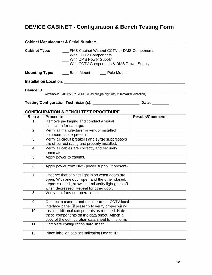
DEVICE CABINET - Configuration & Bench Testing Form Cabinet Manufacturer & Serial Number: _________________________________________ Cabinet Type: ___ FMS Cabinet Without CCTV or DMS Components ___ With CCTV Components ___ With DMS Power Supply ___ With CCTV Components & DMS Power Supply Mounting Type: ___ Base Mount ___ Pole Mount Installation Location: _________________________________________________________ Device ID: __________________________________________________________________ (example: CAB I275 23.4 NB) (Devicetype highway milemarker direction) Testing/Configuration Technician(s): ______________________ Date: ________ CONFIGURATION & BENCH TEST PROCEDURE
Step # Procedure Results/Comments 1 Remove packaging and conduct a visual
inspection for damage.
2 Verify all manufacturer or vendor installed components are present.
3 Verify all circuit breakers and surge suppressors are of correct rating and properly installed.
4 Verify all cables are correctly and securely terminated.
5 Apply power to cabinet.
6 Apply power from DMS power supply (if present)
7 Observe that cabinet light is on when doors are open. With one door open and the other closed, depress door light switch and verify light goes off when depressed. Repeat for other door.
8 Verify that fans are operational.
9 Connect a camera and monitor to the CCTV local interface panel (if present) to verify proper wiring.
10 Install additional components as required. Note these components on the data sheet. Attach a copy of the configuration data sheet to this form.
11 Complete configuration data sheet
12
Place label on cabinet indicating Device ID.

13
DEVICE CABINET - Configuration Data Sheet Cabinet Manufacturer & Serial Number: _________________________________________ Testing/Configuration Technician(s): ______________________ Date: _____________ INSTALLED COMPONENTS & ANCILLARY EQUIPMENT Item Serial Number
14
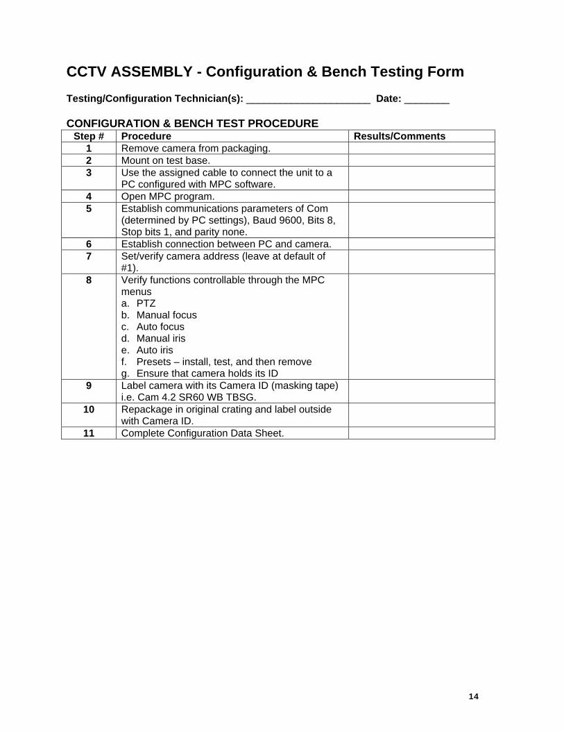
CCTV ASSEMBLY - Configuration & Bench Testing Form Testing/Configuration Technician(s): ______________________ Date: ________ CONFIGURATION & BENCH TEST PROCEDURE
Step # Procedure Results/Comments 1 Remove camera from packaging. 2 Mount on test base. 3 Use the assigned cable to connect the unit to a
PC configured with MPC software.
4 Open MPC program. 5 Establish communications parameters of Com
(determined by PC settings), Baud 9600, Bits 8, Stop bits 1, and parity none.
6 Establish connection between PC and camera. 7 Set/verify camera address (leave at default of
#1).
8 Verify functions controllable through the MPC menus a. PTZ b. Manual focus c. Auto focus d. Manual iris e. Auto iris f. Presets – install, test, and then remove g. Ensure that camera holds its ID
9 Label camera with its Camera ID (masking tape) i.e. Cam 4.2 SR60 WB TBSG.
10 Repackage in original crating and label outside with Camera ID.
11 Complete Configuration Data Sheet.

15
Configuration Data Sheet, CCTV The following data needs to be collected for each CCTV to be configured:
Camera ID Unique name of camera
Center Id Unique name of center where camera resides
Protocol Specifies the protocol (values: SNMP, SNMP (PMPP)) for camera
Poll Process Name of driver for camera Manufacturer Manufacturer of camera Location Description
Description of where camera resides
Roadway Roadway of where camera resides
Direction Direction of roadway where camera is installed
Latitude Latitude of where camera resides
Longitude Longitude of where camera resides
Op Status Operational status (values: Active, Error, Failed, OutOfService) of camera
Address Type1
Address type (values: pmppAddress, commAddress) for camera, if pmppAddress then camera uses SNMP (PMPP); if commAddress then camera uses SNMP
Address Type2 Specific address type (values: portServerAddress) of Address Type 1
Address Device address of camera
Port Server IP IP address for the port server where camera resides
Port Server Port Number
Port number for the port server where camera resides
Community Name Community name for camera (SNMP)
Attach to Video Device
If selected, additional IP video parameters must be supplied.

16
The following data need to be provided for IP video:
Video Device IP Address IP address for encoder
Blackout Determines if camera restricted
Video Device Type Type (IP video device) of video device for encoder
IP Streaming Driver ID
Unique IP video switch driver name
Card Number Card number for VBrick encoder
Manufacturer Manufacturer (values: Coretec, iMpath, Teleste, VBrick) of encoder
Model Model of encoder
Streaming Type Streaming type (values: elementary, transport, program) for encoder
Secondary Interface
Secondary interface for VBrick encoder which enables users to maximize number of inputs for encoder
Snapshot Requested
Determines if snapshots are generated for encoder

17
MVDS - Configuration & Bench Testing Form Testing/Configuration Technician(s): ______________________ Date: ________ CONFIGURATION & BENCH TEST PROCEDURE
Step # Procedure Results/Comments 1 Remove from packaging. 2 Verify all components are present and without
damage, i.e. proper mounting bracket, cable, back plate, breakers, and surge suppressors.
3 Using supplied back plate wiring diagram, connect cable from RTMS unit to back plate, wiring pin 8 for RS-485.
4 Use a serial cable, and the RS-485 to RS-232 converter to connect to the COM port on the PC.
5 Power on the RTMS and wait 5 to 10 seconds. 6 Open the WinRTMS program on the PC and wait
for the RTMS to be read by the program.
7 Select “Zones.” From this screen you can choose the number of lanes and move or resize the lanes using the up/down arrow keys. Ensure that the number of lanes is consistent with the location of planned installation. Exit this screen by choosing “OK.”
8 Unit should now be in operation. Move a solid object back and forth in front of the sensor. The hollow lane markers on the screen should turn solid red as the sensor detects the movement of the object.
9 Select “Tools.” Select “PC COMM.” Click on TCP/IP box. Ensure that default IP of 120.100.101.254 is displayed. Set protocol = TCP, Local Port = 2000, Remote Port = 2000. Click “OK.”
10 Power off unit, close software, move pin 8 to IP position on terminal block, re-power unit, and restart software after 5 to 10 seconds.
11 Use a standard Cat5 Ethernet cable to connect the back plate to a PC loaded with the RTMS software.
12 Configure the PC with an IP address of 128.100.101.1, and a subnet mask of 255.255.0.0. The default IP of the RTMS unit is 128.100.101.254.
13 Open RTMS software. From the main menu select “Read RTMS.” When this has loaded, the screen will show the current lane configuration as a hollow block at the bottom of the screen.
14 Select “Zones.” From this screen you can choose the number of lanes and move or resize

18
the lanes using the up/down arrow keys. Ensure that the number of lanes is consistent with the location of planned installation. Exit this screen by choosing “OK.”
15 Unit should now be in operation. Move a solid object back and forth in front of the sensor. The hollow lane markers on the screen should turn solid red as the sensor detects the movement of the object. Select “Period.” Set the period for 60 seconds using the up/down arrow keys. Click “OK.”
16 Select “ID Number.” Type in ID number for the location assigned to this unit. Click “OK.”
17 Select “Tools.” Select “PC COMM.” Click on TCP/IP box. Type in IP address assigned by System Manager. Set protocol = TCP, Local Port = 2000, Remote Port = 2000. Click “ OK.”
18 Exit software and label unit with Device ID. 19 Repackage all components as required for
delivery to installation contractor and label package with Device ID.
20 Complete Configuration Data Sheet.
Configuration Management Data File
Version Number Version Date
Nomenclature RTMS Manufacturer / Model # EIS / RTMS X3 Serial Number IP Address Device ID Config Technician
Install Location Config Date
# of lanes covered Height / Setback ________ / ________ Median between covered lanes Y ______ N _______ Potential Interference Y ______ / N _______
Install Type Check All that apply
Pole Mount ____ Sign Structure _____ Vertical Bracket ____ Horizontal Bracket ____ Other _____________ ____
Lane Configuration - Numbering scheme / Direction of travel
Installed Components & Ancillary Equipment Installed Components & Ancillary Equipment
Item Serial Number Item Serial Number
Special Back Plate RS 485 to 232 Converter

19
ETHERNET SWITCH - Configuration & Bench Testing Form Testing/Configuration Technician(s): ______________________ Date: ________ CONFIGURATION & BENCH TEST PROCEDURE
Step # Procedure Results/Comments 1 Configure a hyper-terminal connection with the
following parameters: a. Com (per local PC) b. Baud = 115200 c. Bits = 8 d. Parity = none e. Stop Bits = 1 f. Flow = none
2 Connect PC to Etherwan via provided serial cable and open hyper-terminal session.
3 Console Login is admin. Password is (leave blank).
4 Highlight “Switch Management” then a. Highlight “Advanced Management” then hit
“Enter.” i. Highlight “IP Networking” then hit “Enter.”
1. Highlight “IP and RIP Settings” then hit “Enter.” a. Highlight “VLAN ID” to configure
then hit “Enter.” i. Use the up/down arrow keys to
select value to enter then hit “Enter.” 1. Enter IP, Subnet Mask,
and enable RIP V2 then hit esc key three times to return to Advanced Management.
ii. Highlight “Other Protocols” then hit “Enter.” 1. Highlight “IGMP.”
a. Highlight “Mode.” i. Highlight “Passive.” Then hit
esc key three times to get to Switch Management.
b. Highlight “Save Settings” then hit “Enter.” i. Highlight “Yes” then hit esc key once.
1. Highlight “Yes” and hit “Enter” to logout.
5 Label unit with Device ID. 6 Install in appropriate cabinet. 7 Complete Configuration Data Sheet
Configuration Data Sheet, Ethernet Switch
20
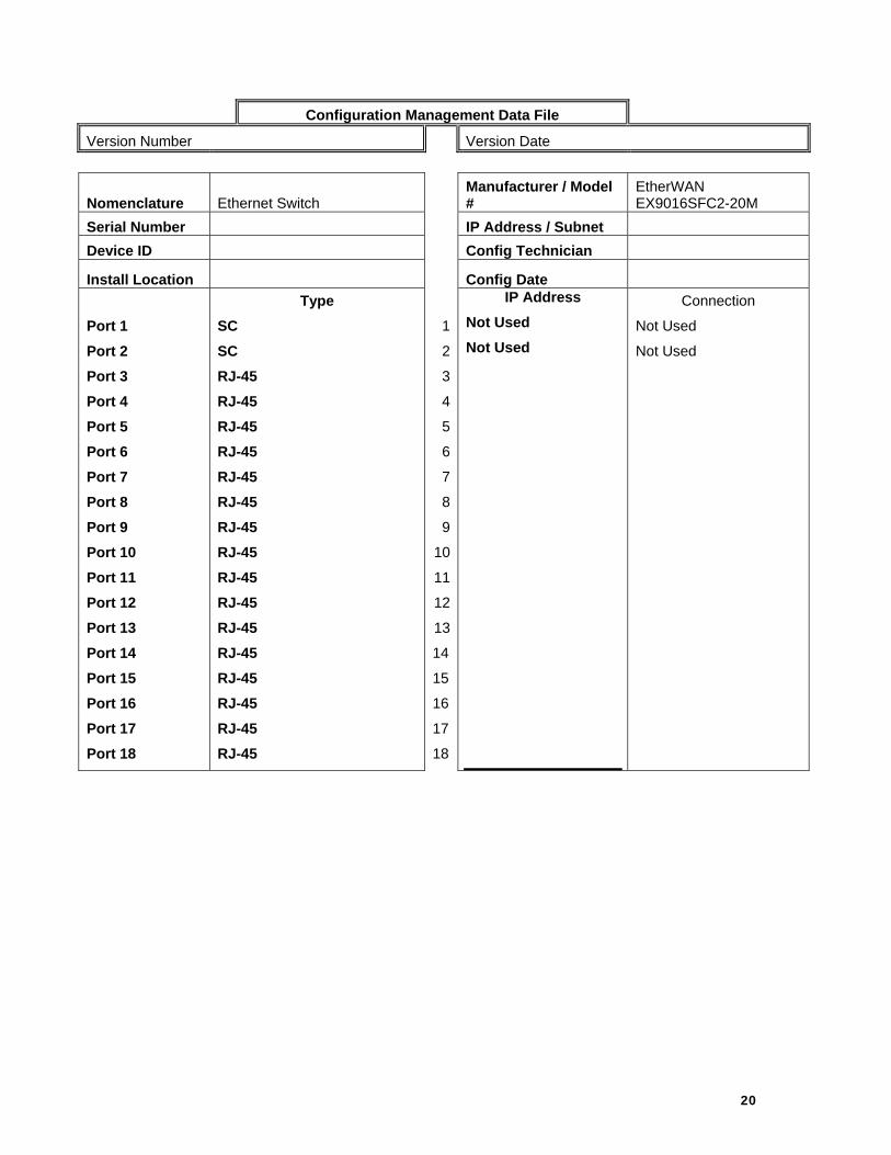
Configuration Management Data File
Version Number Version Date
Nomenclature Ethernet Switch Manufacturer / Model #
EtherWAN EX9016SFC2-20M
Serial Number IP Address / Subnet Device ID Config Technician
Install Location Config Date Port 1 Port 2 Port 3 Port 4 Port 5 Port 6 Port 7 Port 8 Port 9 Port 10 Port 11 Port 12 Port 13 Port 14 Port 15 Port 16 Port 17 Port 18
Type SC SC RJ-45 RJ-45 RJ-45 RJ-45 RJ-45 RJ-45 RJ-45 RJ-45 RJ-45 RJ-45 RJ-45 RJ-45 RJ-45 RJ-45 RJ-45 RJ-45
1
2
3
4
5
6
7
8
9
10
11
12
13
14
15
16
17
18
IP Address Not Used Not Used
Connection
Not Used
Not Used

21
VIDEO ENCODER - Configuration & Bench Testing Form Testing/Configuration Technician(s): ______________________ Date: ________ CONFIGURATION & BENCH TEST PROCEDURE
Step # Procedure Results/Comments 1 Remove unit from packaging. 2 Supply power to the unit via the CPS243 power
adaptor or by installing in a DVX002 installation frame equipped with a DVP power supply.
3 Power on the system and verify that the “M,” “C,” and “V” indicators on the front panel are lit. The “M” should be green to indicate proper operation.
4 Connect audio/data signals to the front panel. 5 Connect either a CVBS video signal to the BNC
connector or an S-video signal to the mini-DIN connector of the device.
6 Connect the Ethernet 100BASE network to port 100BASE-TX/FX on the front panel.
7 Create a management connection to the device either by Ethernet (WebUI) or management port (Hyperterminal) and program all necessary settings. Default settings are: a. IPE: 10.9.96.10 b. IPD: 10.9.96.20 c. IPE/IPD: 255.255.255.0
i. Use EASI IP Series User Manual for WebUI interface instructions.
8 Ensure that “M,” “C,” and “V” are now all green. a. M = hardware state b. C = Ethernet state c. V = video state
9 Refer to EASI IP Series User Manual for questions or troubleshooting.
10 Label unit with Device ID and install in appropriate cabinet.
11 Complete Configuration Data Sheet.

22
Configuration Data Sheet, Video Encoder
Configuration Management Data File
Version Number Version Date
Nomenclature Video Encoder Manufacturer / Model # Teleste IPE301XXXA Serial Number IP Address / Subnet Device ID Config Technician
Software Version Hardware Version Boot Loader Version
Network DHCP Gateway MAC Speed Duplex
Install Location Install Technician Passwords Guest Technician Operator Admin
guest technician oper admin
Video Management QOS Polling Services
Enabled ___ Disabled ___
Video Configuration
IP _________________ UDP _______________ TTL ________________ Input Comp ___ Svid ___ Format PAL ___ NTSC ___ GOP Format ____________
Video Configuration Continued
VIDEO PID ____________ AUDIO PID ____________ PCR PID ______________ PMT PID ______________ Stream Bit Rate _________
SAP Management
Enabled ___ Disabled ____ Multicast Group _________ Port _____ TTL _____ Announcement Interval ____ Session Name ___________ Session Info _____________
Ports
Enabled ___ Disabled ____ Server ____ Client ____ IP ___________________ Port _____ TTL ______ Data Bits ___ Stop Bits ___ Baud ______ COM Port Mode ________

23
WIRELESS RADIOS - Configuration & Bench Testing Form Testing/Configuration Technician(s): ______________________ Date: ________ CONFIGURATION & BENCH TEST PROCEDURE
Step # Procedure Results/Comments 1 Remove unit and accessories from packaging. 2 Inventory all components. 3 Conduct self tests per provided user manual. 4 Set channel assignments for each unit per
provided manual, ensuring ample frequency separation to prevent cross talk.
5 Complete Configuration Data Sheet. 6 Label each unit with Device ID and channel
assignment.
Configuration Data Sheet
Inventory Device Serial Number Quantity Install Location
Configuration Channel Assignment
Mounting Height

24
UPS - Configuration & Bench Testing Form Testing/Configuration Technician(s): ______________________ Date: ________ CONFIGURATION & BENCH TEST PROCEDURE
Step # Procedure Results/Comments 1 Remove unit from packaging. 2 Verify unit will fit in device cabinet as provided by
vendor.
3 Provide appropriate input power to unit. 4 Conduct self tests per provided user manual. 5 Allow unit to reach full charge per provided user
manual.
6 Remove input power source from unit and verify proper operation per provided user manual.
7 Complete Configuration Data Sheet. 8 Label unit with Device ID.
Configuration Data Sheet
Configuration Management Data File
Version Number Version Date
Nomenclature Uninterruptible Power Supply Manufacturer Serial Number Model # Config Date Config Technician Input Power # Outlets Switched ____ Non ____
Install Location Self Tests Pass _____ Fail ______