compressed gaseous fuel measuring systems for vehicles · oiml r 139: 2007 (e) 4 foreword the...
TRANSCRIPT

Compressed gaseous fuel measuring systems for vehicles
Ensembles de mesurage de gaz compressé pour véhicules
OIM
L R
139
Editi
on 2
007
(E)
OIML R 139Edition 2007 (E)
ORGANISATION INTERNATIONALE
DE MÉTROLOGIE LÉGALE
INTERNATIONAL ORGANIZATION
OF LEGAL METROLOGY
INTERNATIONAL
RECOMMENDATION


OIML R 139: 2007 (E)
3
Contents Foreword .................................................................................................................................................4
Terminology ............................................................................................................................................5
1 Scope .....................................................................................................................................11
2 General requirements ..........................................................................................................11
2.1 Constituents of a measuring system .......................................................................................11 2.2 Ancillary and additional devices ............................................................................................11 2.3 Field of operation ...................................................................................................................12 2.4 Indications ..............................................................................................................................13 2.5 Suitability of additional devices .............................................................................................14
3 Metrological requirements for measuring systems and meters .......................................14
3.1 Maximum permissible errors and other metrological characteristics ....................................14 3.2 Conditions for applying maximum permissible errors ...........................................................15
4 Requirements for meters and ancillary devices of a measuring system ..........................16
4.1 Meter ......................................................................................................................................16 4.2 Indicating device ....................................................................................................................17 4.3 Zero setting device .................................................................................................................17 4.4 Price indicating device ...........................................................................................................17 4.5 Printing device .......................................................................................................................18 4.6 Memory device ......................................................................................................................18 4.7 Pre-setting device ...................................................................................................................18 4.8 Calculator ...............................................................................................................................19
5 Technical requirements for electronic devices ..................................................................19
5.1 General requirements .............................................................................................................19 5.2 Power supply device ..............................................................................................................20 5.3 Checking facilities .................................................................................................................20
6 Technical requirements for measuring systems with self-service arrangement ............23
6.1 General requirements .............................................................................................................23 6.2 Attended service mode ...........................................................................................................23 6.3 Unattended service mode .......................................................................................................24
7 Markings and sealing ...........................................................................................................25
7.1 Marking ..................................................................................................................................25 7.2 Sealing devices and stamping plate .......................................................................................26
8 Metrological control .............................................................................................................27
8.1 Type approval ........................................................................................................................28 8.2 Initial verification ...................................................................................................................32 8.3 Subsequent verification ..........................................................................................................33
Annex A (Mandatory) Performance tests for electronic devices of measuring systems ....................34
Annex B (Mandatory) Basic test methods ..........................................................................................46
Annex C (Informative) Minimum test volumes for measuring systems and devices ..........................56
Annex D (Informative) Test methods for influence quantities for Coriolis meters .............................58
Bibliography ..........................................................................................................................................62

OIML R 139: 2007 (E)
4
Foreword
The International Organization of Legal Metrology (OIML) is a worldwide, intergovernmental organization whose primary aim is to harmonize the regulations and metrological controls applied by the national metrological services, or related organizations, of its Member States. The main categories of OIML publications are:
International Recommendations (OIML R), which are model regulations that establish the metrological characteristics required of certain measuring instruments and which specify methods and equipment for checking their conformity. OIML Member States shall implement these Recommendations to the greatest possible extent;
International Documents (OIML D), which are informative in nature and which are intended to harmonize and improve work in the field of legal metrology;
International Guides (OIML G), which are also informative in nature and which are intended to give guidelines for the application of certain requirements to legal metrology; and
International Basic Publications (OIML B), which define the operating rules of the various OIML structures and systems.
OIML Draft Recommendations, Documents and Guides are developed by Technical Committees or Subcommittees which comprise representatives from the Member States. Certain international and regional institutions also participate on a consultation basis. Cooperative agreements have been established between the OIML and certain institutions, such as ISO and the IEC, with the objective of avoiding contradictory requirements. Consequently, manufacturers and users of measuring instruments, test laboratories, etc. may simultaneously apply OIML publications and those of other institutions.
International Recommendations, Documents, Guides and Basic Publications are published in English (E) and translated into French (F) and are subject to periodic revision.
Additionally, the OIML publishes or participates in the publication of Vocabularies (OIML V) and periodically commissions legal metrology experts to write Expert Reports (OIML E). Expert Reports are intended to provide information and advice, and are written solely from the viewpoint of their author, without the involvement of a Technical Committee or Subcommittee, nor that of the CIML. Thus, they do not necessarily represent the views of the OIML.
This publication - reference OIML R 139, edition 2007 (E) - was developed by the OIML Technical Subcommittee TC 8/SC 7 Gas metering. It was approved for final publication by the International Committee of Legal Metrology in 2007 and will be submitted to the International Conference of Legal Metrology in 2008 for formal sanction.
OIML Publications may be downloaded from the OIML web site in the form of PDF files. Additional information on OIML Publications may be obtained from the Organization’s headquarters:
Bureau International de Métrologie Légale 11, rue Turgot - 75009 Paris - France Telephone: 33 (0)1 48 78 12 82 Fax: 33 (0)1 42 82 17 27 E-mail: [email protected] Internet: www.oiml.org

OIML R 139: 2007 (E)
5
Terminology
The terminology used in this Recommendation conforms to the International vocabulary of metrology - Basic and general concepts and associated terms (VIM) [1] and the International vocabulary of terms in legal metrology (VIML) [2]. In addition, for the purposes of this Recommendation, the following definitions apply.
Notes: 1) This terminology must be considered as a part of this Recommendation; 2) The following terminology is classified from a functional point of view.
T.1 Measuring system and its constituents T.1.1 Meter
Instrument intended to measure, memorize and display the quantity of gas passing through the measurement transducer at metering conditions.
Note: A meter includes at least a transducer, a calculator (including adjustment or correction devices if present) and an indicating device.
T.1.2 Measurement transducer
Part of the meter which transforms the flow of the gas to be measured into signals which are passed to the calculator. It may be autonomous or use an external power source.
Note: For the purposes of this Recommendation, the measurement transducer includes the flow or quantity sensor.
T.1.3 Calculator
T.1.3.1 Metering calculator
Part of the meter that receives the output signals from the transducer(s) and, possibly, from associated measuring instruments, transforms them and, if appropriate, stores the results in memory until they are used.
T.1.3.2 Operational calculator
Optional part of the meter that receives the digital output signals from the metering calculator and, possibly, from associated measuring instruments, which processes them into data for the indicating device.
Note: The metering calculator and the operational calculator may be two separate elements or form a single unit. Except in the case of a particular need to dissociate the two kinds of calculators, the association of both functions is called the calculator in this Recommendation.
T.1.4 Indicating device
Part of the meter which displays continuously the measurement results.
Note: A printing device which provides an indication at the end of the measurement is not an indicating device.
T.1.5 Ancillary device
Device intended to perform a particular function, directly involved in elaborating, transmitting or displaying measurement results. Main ancillary devices are:
zero setting device; repeating indicating device; printing device;
OIML R 139: 2007 (E)
6
memory device; price indicating device; totalizing indicating device; pre-setting device; self-service device.
Note: An ancillary device may or may not be subject to legal metrology control according to its function in the measuring system or to national regulations.
T.1.6 Additional device
Part or device, other than an ancillary device, required to ensure correct measurement or intended to facilitate the measuring operations, or which could in any way affect the measurement.
Main additional devices are:
filter; device used for the transfer point; anti-swirl device; branches or bypasses; valves, hoses, and in general, all the gaseous piping.
T.1.7 Measuring system
System which comprises the meter itself and all the ancillary devices and additional devices.
T.1.8 Compressed gaseous fuel measuring systems for vehicles
Measuring system intended for the refueling of motor vehicles with compressed gaseous fuel. Such an instrument is hereafter called a "measuring system".
T.1.9 Pre-setting device
Device which permits the selection of the quantity to be measured and which automatically stops the flow of the gas at the end of the measurement of the selected quantity.
Note: The pre-set quantity may be the mass or the related price to pay.
T.1.10 Adjustment device
Device incorporated in the meter, that only allows shifting of the error curve generally parallel to itself, with a view to bringing errors within the maximum permissible errors.
T.1.11 Associated measuring instruments
Instruments connected to the calculator or the correction device, for measuring certain quantities which are characteristic of the gas, with a view to making a correction.
T.1.12 Correction device
Device connected to or incorporated in the meter for automatically correcting the mass, by taking into account the flowrate and/or the characteristics of the gas to be measured (viscosity, temperature, pressure, etc.) and the pre-established calibration curves.
T.1.13 Transfer point
Point at which the gas is defined as being delivered.

OIML R 139: 2007 (E)
7
T.2 Self-service measuring systems T.2.1 Self-service arrangement
Arrangement that allows the customer to use a measuring system for the purpose of obtaining gas for his own purchase.
T.2.2 Self-service device
Specific device that is part of a self-service arrangement and which allows one or more measuring systems to perform in this self-service arrangement.
Notes: The self-service device includes all the elements and constituents that are mandatory so that a measuring system performs in a self-service arrangement.
The arrangement is made of a self-service device and connected measuring systems.
T.2.3 Attended service mode
Operating mode of a self-service arrangement in which the supplier is present and controls the authorization for the delivery.
Notes:
1) In attended service mode, the settlement of the transaction takes place before the customer leaves the site of the delivery.
2) A transaction is settled when the parties interested in the transaction have made their agreement known (explicitly or implicitly) as regards the amount of the transaction. This may be a payment, signing a credit card voucher, signing a delivery order, etc.
3) The parties interested in a transaction may be the parties themselves or their representatives (for example: an employee in a filling station, or the driver of a truck).
4) In attended service mode the measurement operation ends at the moment settlement of the transaction takes place.
T.2.4 Unattended service mode
Operating mode of a self-service arrangement in which the self-service arrangement controls the authorization for the delivery, based on an action of the customer.
Note: In unattended service mode, the end of the measurement operation is the end of the registration (printing and/or memorizing) of information concerning the measurement operation.
T.2.5 Pre-payment
Type of payment in attended or unattended service mode requiring payment for a quantity of gas before the delivery commences.
T.2.6 Attended post-payment (or post-payment)
Type of payment in attended service mode requiring payment for the delivered quantity after the delivery but before the customer leaves the site of the delivery.
T.2.7 Unattended post-payment (or delayed payment)
Type of payment in unattended service mode in which payment for the delivered quantity is required after the delivery, but in which the transaction is not settled when the customer leaves the site, following an implicit agreement with the supplier.

OIML R 139: 2007 (E)
8
T.2.8 Authorization of a measuring system
Operation that brings the measuring system into a condition suitable for the commencement of the delivery.
T.3 Metrological characteristics T.3.1 Primary indication
Indication (displayed, printed or memorized) which is subject to legal metrology control.
Note: Indications other than primary indications are commonly referred to as secondary indications.
T.3.2 Absolute error of measurement
Result of a measurement minus the (conventional) true value of the measurand.
T.3.3 Relative error
Absolute error of measurement divided by the (conventional) true value of the measurand.
T.3.4 Maximum permissible errors
Extreme values permitted by the present Recommendation for an error.
Notes:
1) In this text, maximum permissible errors are stated, according to the case, as relative errors (general case) or absolute errors.
2) To simplify writing, some specifications in the present text involve the comparison of a quantity (for instance: difference between a result obtained at some specified conditions and a result obtained at reference conditions) with maximum permissible error. In this case, it is obvious that it is the absolute maximum permissible error, associated with the relative maximum permissible error, which applies.
T.3.5 Minimum measured quantity of a measuring system
Smallest mass of gas for which the measurement is metrologically acceptable for that system.
Note: This smallest mass is also referred to as the minimum delivery.
T.3.6 Minimum specified mass deviation
Absolute value of the maximum permissible error for the minimum measured quantity of a measuring system.
T.3.7 Durability
Capability of the measuring system to keep its performance characteristics over a period of use, for electronic purposes.
T.3.8 Repeatability error
For the purposes of this Recommendation: difference between the largest and the smallest results of successive measurements of the same quantity carried out under the same conditions.
T.3.9 Intrinsic error
Error of a measuring system determined under reference conditions.

OIML R 139: 2007 (E)
9
T.3.10 Initial intrinsic error
Intrinsic error of a measuring system as determined prior to all performance tests.
T.3.11 Fault
Difference between the error of indication and the intrinsic error of a measuring system.
T.3.12 Significant fault
For the mass, a fault the magnitude of which is greater than the larger of these two values:
one tenth of the magnitude of the maximum permissible error for the measuring system and for the measured mass,
the minimum specified mass deviation.
For the price to pay, the price corresponding to the significant fault for the mass.
Note: No fault is allowed for the unit price.
The following are not considered to be significant faults:
faults arising from simultaneous and mutually independent causes in the measuring instrument itself or in its checking facilities,
transitory faults being momentary variations in the indication, which cannot be interpreted, memorized or transmitted as a measurement result,
faults implying the impossibility of performing any measurement.
T.4 Tests and test conditions T.4.1 Influence quantity
Quantity which is not the subject of the measurement but which influences the value of the measurand or the indication of the measuring system.
T.4.2 Influence factor
Influence quantity having a value within the rated operating conditions of the measuring system, as specified in this International Recommendation.
T.4.3 Disturbance
Influence quantity having a value outside the specified rated operating conditions of the measuring system.
Note: An influence quantity is a disturbance if for that influence quantity the rated operating conditions are not specified.
T.4.4 Rated operating conditions
Conditions of use, giving the range of values of influence quantities for which the metrological characteristics are intended to be within the maximum permissible errors.
T.4.5 Reference conditions
Set of specified values for influence factors that are fixed to ensure valid intercomparison of results of measurements.
T.4.6 Performance test
Test intended to verify whether the measuring system under test (EUT) is capable of accomplishing its intended functions.

OIML R 139: 2007 (E)
10
T.4.7 Endurance test
Test intended to verify whether the meter or the measuring system is able to maintain its performance characteristics over a period of use.
T.4.8 Bank
Test reservoir or a set of test reservoirs manifolded together which forms part of a multi-segment gas storage system. The segments operate at different pressure levels from one another in refueling systems fitted with or using a sequential control device (see T.4.9 below).
Note: Testing using banks generates transient flowrates.
T.4.9 Sequential control device
Device which allows switching from one bank to another. This device may be included in a measuring system or may be part of the refueling station.
T.5 Electronic or electrical equipment T.5.1 Electronic device
Device employing electronic sub-assemblies and performing a specific function. Electronic devices are usually manufactured as separate units and are capable of being tested independently.
Note: Electronic devices, as defined above, may be complete measuring systems or part of measuring systems, in particular such as those mentioned in T.1.1 through T.1.5.
T.5.2 Electronic sub-assembly
Part of an electronic device, employing electronic components and having a recognizable function of its own.
T.5.3 Electronic component
Smallest physical entity which uses electron or hole conduction in semiconductors, gases, or in a vacuum.
T.5.4 Checking facility
Facility which is incorporated in a measuring system and which enables significant faults to be detected and acted upon.
Note: The checking of a transmission device aims at verifying that all the information which is transmitted (and only that information) is fully received by the receiving equipment.
T.5.5 Automatic checking facility
Checking facility operating without the intervention of an operator.
T.5.6 Permanent automatic checking facility (type P)
Automatic checking facility operating during the entire measurement operation.
T.5.7 Intermittent automatic checking facility (type I)
Automatic checking facility operating at least once, either at the beginning or at the end of each measurement operation.
T.5.8 Power supply device
Device which provides the electronic devices with the required electrical energy, using one or several sources of AC or DC.

OIML R 139: 2007 (E)
11
Compressed gaseous fuel measuring systems for vehicles
1 Scope This International Recommendation specifies the metrological and technical requirements applicable to compressed gaseous fuel measuring systems for vehicles, at type approval, initial verification and subsequent verifications. It also provides requirements for the approval of constituent elements of the measuring systems (meter, etc.). Measuring systems for liquid petroleum gas do not fall within the scope of this Recommendation, but within that of OIML R 117 as the fluid is in a liquid state.
In general, the measuring systems that are covered by this Recommendation are intended for the refueling of motor vehicles, small boats, and aircraft with compressed natural gas. Applications with other compressed gaseous fuels are covered. Application to other vehicles, for instance trains, are also possible. Member States are free to limit the applications subject to national legal metrology control.
In principle, this Recommendation applies to all measuring systems fitted with a meter as defined in T.1.1 (continuous measurement), whatever may be the measuring principle of the meters or their application.
This Recommendation is not intended to prevent the development of new technologies. According to the state of the art, this Recommendation is intended for measuring systems that provide mass indications. If further evolution of technology allows indications in other units of measurement, this Recommendation will have to be revised.
2 General requirements 2.1 Constituents of a measuring system
A meter itself is not a measuring system. A measuring system includes at least:
a meter, a transfer point, the gas piping that has particular characteristics which can influence the metrological
performances and which must be taken into account.
The measuring system may be provided with other ancillary and additional devices (see 2.2).
If several meters intended for separate measuring operations have common elements (calculator filter, etc.) each meter is considered to form, with the common elements, a measuring system.
A measuring system shall include only one meter.
2.2 Ancillary and additional devices
2.2.1 Ancillary devices may be a part of the calculator or of the meter, or may be peripheral equipment, connected through an interface to the calculator (for example).
As a rule these ancillary devices are optional. However, this Recommendation may make some of them mandatory, or prohibit some of them. In addition, national or international regulations may make some of these devices mandatory in relation to the utilization of the measuring systems.

OIML R 139: 2007 (E)
12
2.2.2 When these ancillary devices are mandatory in application of this Recommendation or of a national or international regulation, they are considered as integral parts of the measuring system, they are subject to control, and they shall meet the requirements of this Recommendation.
2.2.3 When ancillary devices are not subject to control, one shall verify that these devices do not affect the correct operation of the measuring system. In particular, the system shall continue to operate correctly and its metrological functions shall not be affected when the peripheral equipment is connected or disconnected.
In addition, these devices shall bear a legend which is clearly visible to the user to indicate that they are not controlled when they display a measurement result visible to the user. Such a legend shall be present on each printout likely to be made available to the customer.
2.2.4 By definition, additional devices likely to be installed in a measuring system shall not corrupt the metrological behavior of the measuring apparatus.
2.3 Field of operation
2.3.1 The field of operation of a measuring system is to be specified by the manufacturer and is determined by the following characteristics:
minimum measured quantity, measuring range limited by the minimum flowrate, Qmin, and the maximum flowrate,
Qmax, maximum pressure of the gas in the refueling station gas storage, Pst, maximum fast fill pressure of the gas-fuelled vehicle, Pv, if critical, minimum pressure of the gas, Pmin, if appropriate, nature and characteristics of the gases to be measured, maximum temperature of the gas, Tmax, minimum temperature of the gas, Tmin, environmental class (see A.2).
The maximum and minimum temperatures of the gas are those in the measuring transducer when measuring.
The environmental class may be different according to devices of the measuring system, provided each device is used according to its own environmental class. In particular this is applicable to some parts of a self-service device which can be used at different temperatures than the rest of the measuring system.
2.3.2 The minimum measured quantity of a measuring system shall be of the form 1 × 10n, 2 × 10n or 5 × 10n kg, where n is a positive or negative whole number, or zero.
The minimum measured quantity shall satisfy the conditions of use of the measuring system. Except in exceptional cases, the measuring system shall not be used for measuring quantities less than this minimum measured quantity.
Measuring systems having a maximum flowrate not greater than 30 kg/min shall have a minimum measured quantity not exceeding 2 kg.
Measuring systems having a maximum flowrate larger than 30 kg/min but not greater than 70 kg/min shall have a minimum measured quantity not exceeding 5 kg.
Measuring systems having a maximum flowrate greater than 70 kg/min shall have a minimum measured quantity not exceeding 10 kg.
2.3.3 The measuring range shall satisfy the conditions of use of the measuring system; the latter shall be designed so that the flowrate is between the minimum flowrate and the maximum flowrate,

OIML R 139: 2007 (E)
13
except at the beginning and at the end of the measurement or during interruptions.
In normal conditions of use, a flow control system shall prevent the delivery of flowrates smaller than the minimum flowrate of the measuring system. The measuring range of a measuring system shall be within the measuring range of each of its elements.
The ratio between the maximum flowrate and the minimum flowrate shall be at least 10.
2.3.4 A measuring system shall exclusively be used for measuring gas having characteristics within its field of operation, as specified in the type approval certificate. The field of operation of a measuring system shall be within the fields of measurement of each of its constituent elements, in particular the meter.
2.4 Indications
2.4.1 Measuring systems shall be provided with an indicating device giving the mass of gas measured.
However, the national authority may allow the mass indication to be complemented with a secondary (informative) indication of volume, energy or other quantity, provided the status of this informative indication is clear and unambiguous and is not misleading with respect to the actual amount. Moreover in this case, the conversion factor used for converting from mass to the secondary indication shall be displayed on the front face of the measuring system. Only rounding errors are permitted on conversion.
If the system is fitted with a price indicating device, the national authority should impose that:
indications of unit price and price to be paid are related only to mass, these indications are displayed only when displaying the mass.
2.4.2 Mass shall only be indicated in kilograms. The symbol or the name of the unit shall appear in the immediate vicinity of the indication.
If applicable, volume or other quantities shall be indicated in measurement units allowed by the national metrological authority.
2.4.3 A measuring system may have several devices indicating the same quantity. Each shall meet the requirements of this Recommendation if subject to control. The scale intervals of the various indications shall be the same.
2.4.4 For any measured quantity relating to the same measurement, the indications provided by various devices shall not deviate one from another.
2.4.5 The use of the same indicating device for the indications of several measuring systems (which then have a common indicating device) is authorized provided that it is impossible to use any two of these measuring systems simultaneously, and that the measuring system providing the indication is clearly identified.
2.4.6 The scale interval shall be of the form 1 × 10n, 2 × 10n or 5 × 10n kg, where n is a positive or negative whole number, or zero.
The scale interval shall be equal to or smaller than half the minimum specified mass deviation (see 3.1.3).
However, non-significant scale intervals should be avoided. This does not apply to price indications.
2.4.7 When relevant, the provisions relating to mass indications also apply by analogy to price indications and to secondary indications of other quantities as well.

OIML R 139: 2007 (E)
14
2.5 Suitability of additional devices
2.5.1 Measuring systems shall incorporate a transfer point. This transfer point is located downstream of the meter.
2.5.2 No means shall be provided by which any measured gas can be diverted downstream of the meter during a filling operation.
2.5.3 Two or more delivery transfer points may be permanently installed and operated simultaneously or alternately provided so that any diversion of gas to other than the intended receiving receptacle(s) cannot be readily accomplished or is readily apparent. Such means include, for example, physical barriers, visible valves or indications that make it clear which transfer points are in operation, and explanatory signs, if necessary. The National Authority may impose the solution in order to prevent diversion of gas.
2.5.4 When only one transfer point can be used during a delivery, and after the transfer point has been replaced, the next delivery shall be inhibited until the indicating device has been reset to zero.
When two or more transfer points can be used simultaneously or alternately, and after the utilized transfer points have been replaced, the next delivery shall be inhibited until the indicating device has been reset to zero. Moreover, by design, the provisions of 2.5.3 shall be fulfilled.
2.5.5 The system shall be designed in order to ensure that the measured quantity is delivered. In particular, if the hose downstream of the meter is likely to be depressurized between two deliveries this shall lead for instance to systematic correction or repressurizing before counting for the next delivery.
Whatever the operating principle is (depressurizing or not), in particular whatever constitutes the hose or the transfer point, in the worst measuring conditions, the mass which is measured but not delivered shall be smaller than or equal to half the minimum specified mass deviation if it is not corrected for.
Note: The purpose of this provision is not to allow a systematic deviation. This requirement is verified by design examination, tests and/or calculation.
2.5.6 If there is a risk that the supply conditions can provide a flowrate exceeding the Qmax of the measuring system, a flow limiting device shall be provided. It shall be possible to seal it.
2.5.7 There shall be provision for fitting and removing a pressure gauge on the measuring system in order to check Pmax, and, if critical, Pmin.
3 Metrological requirements for measuring systems and meters 3.1 Maximum permissible errors (MPEs) and other metrological characteristics
3.1.1 Without prejudice to 3.1.3, the maximum permissible relative errors on mass indications, positive or negative, at type approval are equal to:
1 % of the measured quantity for the meter alone and,
1.5 % of the measured quantity for the complete measuring system.
These values also apply to tests at initial verification performed in a laboratory.
However, the MPEs of 1.5 % of the measured quantity apply when the complete measuring system is fitted with a hose the length of which is shorter than or equal to 5 m. When the hose length is larger that this value the MPEs, positive or negative, are equal to 2 % of the measured quantity for the complete measuring system. The test report and the type approval certificate

OIML R 139: 2007 (E)
15
shall clearly indicate the maximum length allowed for the hose. Where in this Recommendation reference to MPEs applicable to the measuring system is made for aspects that are not linked to the hose length, the value 1.5 % applies.
3.1.2 The maximum permissible relative errors on mass indications, positive or negative, at initial verification performed under rated operating conditions on-site of use or at subsequent verifications, are equal to 2 % of the measured quantity for the complete measuring system.
3.1.3 The maximum permissible errors applicable to the minimum measured quantity are twice the corresponding values stated in 3.1.1.
So the minimum specified mass deviation (Emin) for the measuring system is given by the formula:
Emin = 3 × Mmin/100
Where Mmin is the minimum measured quantity having the form specified in 2.3.2.
Note: The minimum specified mass deviation is an absolute maximum permissible error.
3.1.4 Whatever the measured quantity may be, the magnitude of the maximum permissible error (expressed as an absolute error) for the complete system is never less than the minimum specified mass deviation.
3.1.5 For any quantity equal to or greater than 1000 scale intervals of the meter, the repeatability error of the meter tested at constant flowrate shall not be greater than 0.6 %.
3.1.6 For any quantity equal to or greater than 1000 scale intervals of the meter, the repeatability error of the measuring system or of the meter tested in dynamic flow conditions shall not be greater than 1 %.
3.1.7 Within their field of operation, meters shall present a magnitude of the difference between the initial intrinsic error and the error after the endurance test equal to or less than ± 1 %.
The requirement on repeatability applies also to measurements performed after the endurance test.
3.2 Conditions for applying maximum permissible errors
3.2.1 All maximum permissible errors apply for all gases to be metered, all possible ambient conditions of temperatures and pressures, and all flowrates for which the system or the meter is intended to be approved.
A measuring system or a meter shall be capable of fulfilling all requirements without adjustment or modification during the relevant evaluation procedure.
3.2.2 When stated in the pattern approval certificate, verification of a measuring system or of a meter intended to measure gas may be carried out with air (or with another fluid). In this case and if necessary, the pattern approval certificate provides a smaller range or a shift for maximum permissible errors, so that maximum permissible errors are fulfilled for gas.

OIML R 139: 2007 (E)
16
4 Requirements for meters and ancillary devices of a measuring system
The meter and ancillary devices of a measuring system shall meet the following requirements, whether or not they are subject to a separate pattern approval.
4.1 Meter
4.1.1 Field of operation
The field of operation of a meter is to be specified by the manufacturer and is determined at least by the following characteristics:
measuring range limited by the minimum flowrate, Qmin, and the maximum flowrate, Qmax, maximum pressure of the gas, Pmax, if critical, minimum pressure of the gas, Pmin, if appropriate, nature and characteristics of the gases to be measured, maximum temperature of the gas, Tmax, minimum temperature of the gas, Tmin.
The range shall cover at least + 10 °C to + 40 °C and unless otherwise specified is assumed to be – 10 °C to + 50 °C. In any case the range shall suit the conditions of use.
4.1.2 Metrological requirements
See clause 3.
4.1.3 Connections between the flow sensor and the indicating device
The connections between the flow sensor and the indicating device shall be reliable and, for electronic devices, durable, in accordance with 5.1.3, 5.3.2 and 5.3.4.
4.1.4 Adjustment device
Meters may be provided with an adjustment device which permits modification of the ratio between the indicated mass and the actual mass of gas passing through the meter, by a simple command.
When this adjustment device modifies this ratio in a discontinuous manner, the consecutive values of the ratio shall not differ by more than 0.001.
Adjustment by means of a bypass of the meter is prohibited.
4.1.5 Correction device
Meters may be fitted with correction devices; such devices are always considered as an integral part of the meter. The whole of the requirements which apply to the meter, in particular the maximum permissible errors specified in clause 3, are therefore applicable to the corrected mass.
In normal operation, non-corrected mass shall not be displayed.
The aim of a correction device is to reduce the errors as close to zero as possible.
Note: National regulations should state that the use of this device for adjusting the errors of a meter to values other than as close as practical to zero is forbidden, even when these values are within the maximum permissible errors.
The type approval certificate may prescribe the possibility of checking parameters that are necessary for correctness at the time of verification of the correction device.
The correction device shall not allow the correction of a pre-estimated drift in relation to time or mass,

OIML R 139: 2007 (E)
17
for example.
The associated measuring instruments, if any, shall comply with the applicable International Standards or Recommendations. Their accuracy shall be good enough to permit the requirements on the meter to be met, as specified in clause 3.
Associated measuring instruments shall be fitted with checking devices, as specified in 5.3.6.
4.2 Indicating device
4.2.1 Measuring systems shall be equipped with digital indicating devices. The decimal sign shall appear distinctly.
4.2.2 The continuous display of mass during the period of measurement is mandatory.
4.2.3 The height for the figures of the indicating device shall be equal to or greater than 10 mm.
4.3 Zero-setting device
4.3.1 Measuring systems shall be equipped with a device for resetting the mass indicating device to zero.
4.3.1.1 The zero setting device shall not permit any alteration of the measurement result shown by the mass indicating device (other than by making the result disappear and displaying zeros).
4.3.1.2 Once the zeroing operation has begun it shall be impossible for the mass indicating device to show a result different from that of the measurement which has just been made, until the zeroing operation has been completed.
The measuring system shall not be capable of being reset to zero during measurement.
4.3.2 If the system also includes a price indicating device, this indicating device shall be fitted with a zero resetting device.
The zero setting devices of the price indicating device and of the mass indicating device shall be designed in such a way that zeroing either indicating device automatically involves zeroing the other.
4.3.3 If the measuring system is fitted with a printing device, any printing operation shall not be possible in the course of a measurement and further delivery shall only be possible after a reset to zero has been performed. However, the printing operation shall not change the quantity indicated on the indicating device.
4.3.4 If the measuring system is designed so that registration of mass could occur without any effective flowrate, a device shall register this apparent flowrate and compensate the measurement result for it.
4.4 Price indicating device
4.4.1 A mass indicating device may be complemented with a price indicating device which displays both the unit price and the price to be paid.
The monetary unit used, or its symbol, shall appear in the immediate vicinity of the indication.
4.4.2 The selected unit price shall be displayed by an indicating device before the start of the measurement. The unit price shall be adjustable; changing the unit price may be carried out either directly on the measuring system or through peripheral equipment.
The indicated unit price at the start of a measurement operation shall be valid for the whole transaction. A new unit price shall only be effective at the moment a new measurement operation may start.
OIML R 139: 2007 (E)
18
A time of at least 5 s shall elapse between indicating a new unit price and before the next measurement operation can start, if the unit price is set from peripheral equipment.
4.4.3 Only rounded errors pertaining to the least significant digit of the price to be paid are authorized.
4.5 Printing device
4.5.1 The mass printed shall be expressed in kg.
The figures, the unit used or its symbol and the decimal sign, if any, shall be printed on the ticket by the device.
4.5.2 The printing device may also print information identifying the measurement such as: sequence number, date, identification of the measuring system, type of gas, etc.
If the printing device is connected to more than one measuring system, it must print the identification of the relevant system.
4.5.3 If a printing device allows repetition of the printing before a new delivery has started, copies shall be clearly marked as such, for example by printing "duplicate".
4.5.4 The printing device may print, in addition to the measured quantity, either the corresponding price or this price and the unit price.
4.5.5 The printing devices are also subject to the requirements in 5.3.5.
4.6 Memory device
4.6.1 Measuring systems may be fitted with a memory device to store measurement results until their use or to keep a trace of commercial transactions, providing proof in case of a dispute. Devices used to read stored information are considered as included in the memory devices.
4.6.2 The medium on which data are stored must have sufficient permanency to ensure that the data are not corrupted under normal storage conditions. There shall be sufficient memory storage for any particular application (for roadside measuring systems storage for three months corresponding to normal use is advisable).
4.6.3 When the storage is full, it is permitted to delete memorized data when both the following conditions are met:
data are deleted in the same order as the recording order and the rules established for the particular application are respected,
deletion is carried out after a special manual operation.
4.6.4 Memorization shall be such that it is impossible in normal use to modify stored values.
4.6.5 Memory devices shall be fitted with checking facilities according to 5.3.5. The aim of the checking facility is to ensure that stored data correspond to the data provided by the calculator and that restored data correspond to stored data.
4.7 Pre-setting device
Measuring systems may be provided with a pre-setting device.
4.7.1 The selected quantity is pre-set by operating a digital device which indicates that quantity. The preset quantity shall be indicated before the start of the measurement.
4.7.2 Where it is possible to simultaneously view the figures of the display device of the pre-setting device and those of the mass indicating device, the former shall be clearly distinguishable from the latter.
OIML R 139: 2007 (E)
19
4.7.3 Indication of the selected quantity may, during measurement, either remain unaltered or return progressively to zero. However, it is acceptable to indicate the preset value on the indicating device for mass by means of a special operation with the restriction that this value shall be replaced by the zero indication for mass before the measurement operation can start.
4.7.4 The difference found under normal operating conditions, between the pre-set quantity and the quantity shown by the mass indicating device at the end of the measurement operation, shall not exceed the minimum specified mass deviation.
4.7.5 The pre-set quantities shall be expressed in kilogram. This unit or its symbol (kg) shall be marked on the pre-setting device.
4.7.6 The scale interval of the pre-setting device shall be equal to the scale interval of the indicating device.
4.7.7 Pre-setting devices may incorporate a device to permit the flow of gas to be stopped quickly when necessary.
4.7.8 Measuring systems with a price indicating device may also be fitted with a price pre-setting device which stops the flow of the gas when the quantity delivered corresponds to the pre-set price. The requirements in 4.7.1 to 4.7.7 apply by analogy.
4.8 Calculator
4.8.1 The maximum permissible errors, positive or negative, on the gas quantity indications applicable for the calculators when they are checked separately are equal to 0.05 % of the true value. If applicable they apply to the metering calculator and to the operational calculator.
4.8.2 All parameters necessary for the elaboration of indications that are subject to legal metrology control, such as unit price, calculation table, correction polynomial, etc. shall be present in the calculator at the beginning of the measurement operation.
4.8.3 The calculator may be provided with interfaces permitting the coupling of peripheral equipment. When these interfaces are used, the instrument shall continue to function correctly and its metrological functions shall not be capable of being affected.
5 Technical requirements for electronic devices 5.1 General requirements
5.1.1 Electronic measuring systems shall be designed and manufactured such that their metrological functions are safeguarded and their errors do not exceed the maximum permissible errors as defined in 3.1 under rated operating conditions.
Note: National or regional regulations may allow the manufacturer to be responsible for the continuation of operation under rated conditions. These regulations shall define the conditions of this responsibility and the information required on the type approval certificate (see also 8.1.2). This may allow the manufacturer to replace purely digital elements (elements which can not influence the characteristics and/or the performance of the measuring systems) by other functionally-equivalent elements without having to demonstrate that the measuring instrument continues to operate as designed.
5.1.2 Electronic measuring systems shall be designed and manufactured such that, when they are exposed to the disturbances specified in A.4:
either a) significant faults do not occur,
or b) significant faults are detected and acted upon by means of checking facilities.

OIML R 139: 2007 (E)
20
This provision may apply separately to:
each individual cause of significant fault, and/or
each part of the measuring system.
5.1.3 The requirements in 5.1.1 and 5.1.2 shall be met durably. For this purpose electronic measuring systems shall be provided with the checking facilities specified in 5.3.
5.1.4 A type of a measuring system is presumed to comply with the requirements in 5.1 if it passes the examination and tests specified in 8.1.9.1 and 8.1.9.2.
5.2 Power supply device
5.2.1 A measuring system shall be provided with an emergency power supply device allowing:
either a) all measuring functions to be safeguarded during a failure of the principal power supply,
or b) that data contained at the moment of a failure leading to stopping the flow are saved and displayable on an indicating device subject to legal metrology control for sufficient time to permit the conclusion of the current transaction.
The absolute value of the maximum permissible error for the indicated mass, in the second case, is increased by 5 % of the minimum measured quantity.
5.2.2 In case of a failure leading to stopping the flow, measuring systems shall be such that the minimum duration of operation of the display shall be either:
continuously and automatically at least 15 min following immediately the failure of the principal electrical supply, or
a total of at least 5 min in one or several periods controlled manually during one hour following immediately the failure.
Note: If a test during type approval is necessary to verify that the measuring system fulfils this requirement, the instrument has to be supplied with electric power normally for the 12 hours which preceded the test. Before this supply the battery (if provided) may be uncharged.
In addition, measuring systems shall be designed so that an interrupted delivery cannot be continued after the power supply device has been re-established if the power failure has lasted more than 15 s.
5.3 Checking facilities
5.3.1 Action of checking facilities
The detection by the checking facilities of significant faults shall result in the following actions:
automatic correction of the fault, or
stopping only the faulty device, when the measuring system without that device continues to comply with the regulations, or
stopping the flow.
5.3.2 Checking facilities for the measurement transducer
The objective of these checking facilities is to verify the presence of the transducer, its correct operation and the correctness of data transmission.
These checking facilities shall be of type P and the checking shall occur at time intervals not exceeding the duration of the measurement of an amount of gas equal to the minimum specified

OIML R 139: 2007 (E)
21
mass deviation.
It shall be possible during type approval to check that these checking facilities function correctly:
by disconnecting the transducer, or by interrupting one of the sensor's pulse generators, or by interrupting the electrical supply of the transducer.
This checking shall also be possible at initial verification unless the presence and the efficiency of the checking facility is ensured by the conformity to type.
5.3.3 Checking facilities for the calculator
The objective of these checking facilities is to verify that the calculator system functions correctly and to ensure the validity of the calculations made.
There are no special means required for indicating that these checking facilities function correctly.
5.3.3.1 The checking of the functioning of the calculation system shall be of types P or I. In the latter case, the checking shall occur at least every five minutes in the course of a delivery but at least once during a delivery.
The objective of the checking is to verify that:
a) The values of all permanently memorized instructions and data are correct, by such means as:
summing up all instruction and data codes and comparing the sum with a fixed value,
line and column parity bits (LRC and VRC), cyclic redundancy check (CRC 16), double independent storage of data, storage of data in "safe coding", for example protected by checksum, line and
column parity bits,
b) All procedures of internal transfer and storage of data relevant to the measurement result are performed correctly, by such means as:
write-read routine, conversion and reconversion of codes, use of "safe coding" (check sum, parity bit), double storage.
5.3.3.2 The checking of the validity of calculations shall be of type P. This consists of checking the correct value of all data related to the measurement whenever these data are internally stored or transmitted to peripheral equipment through an interface; this check may be carried out by such means as parity bit, check sum or double storage. In addition, the calculation system shall be provided with a means of controlling the continuity of the calculation program.
5.3.4 Checking facility for the indicating device
The objective of this checking facility is to verify that the primary indications are displayed and that they correspond to the data provided by the calculator. In addition, it aims at verifying the presence of the indicating devices, when they are removable. The control may be performed according to either the first possibility in 5.3.4.2. or the second possibility in 5.3.4.3.
5.3.4.1 Unless the presence and the efficiency of the checking facility is ensured by the conformity to type, it shall be possible during verification to determine that the checking facility of the

OIML R 139: 2007 (E)
22
indicating device is working, either:
by disconnecting all or part of the indicating device, or by an action which simulates a failure in the display, such as using a test button.
5.3.4.2 The first possibility is to control automatically the complete indicating device. The checking facility of the indicating device is of type P; however, it may be of type I if a primary indication is provided by another device of the measuring system, or if the indication may be easily determined from other primary indications (for example, in the case of the presence of a price indicating device it is possible to determine the price to pay from the mass and the unit price).
Means may include, for example:
for indicating devices using incandescent filaments or LEDs, measuring the current in the filaments,
for indicating devices using fluorescent tubes, measuring the grid voltage, for indicating devices using electromagnetic shutters, checking the impact of each
shutter, for indicating devices using multiplexed liquid crystals, output checking of the
control voltage of segment lines and of common electrodes, so as to detect any disconnection or short circuit between control circuits.
5.3.4.3 The second possibility is to check both:
a) automatically the electronic circuits used for the indicating device except the driving circuits of the display itself, and
b) the display.
The automatic checking facility of the electronic circuits used for the indicating device is of type P; however, it may be of type I if a primary indication is provided by another device of the measuring system, or if the indication may be easily determined from other primary indications (for example, in the case of the presence of a price indicating device it is possible to determine the price to pay from the mass and the unit price).
The checking facility of the display shall provide visual checking of the entire display which shall meet the following description:
displaying all the elements ("eights" test if appropriate), blanking all the elements ("blank" test), displaying "zeros".
Each step of the sequence shall last at least 0.75 s.
This visual checking facility shall be of type I but it is not mandatory for a malfunction to result in the actions described in 5.3.1.
5.3.5 Checking facilities for ancillary devices
An ancillary device (repeating device, printing device, self-service device, memory device, etc.) with primary indications shall include a checking facility of type I or P. The object of this checking facility is to verify the presence of the ancillary device, when it is a necessary device, and to verify the correct transmission of data from the calculator to the ancillary device.
In particular, the checking of a printing device aims at ensuring that the printing controls correspond to the data transmitted by the calculator. At least the following shall be checked:
presence of paper, the electronic control circuits (except the driving circuits of the printing mechanism
itself).
OIML R 139: 2007 (E)
23
It shall be possible during type approval to check that the checking facility of the printing device is functioning by an action simulating a printing fault, such as using a test-button. This checking shall be also possible at initial verification unless the presence and the efficiency of the checking facility is ensured by the conformity to type.
Where the action of the checking facility is a warning, this shall be given on or by the ancillary device concerned.
5.3.6 Checking facilities for the associated measuring instruments
Associated measuring instruments shall include a checking facility of type P. The aim of this checking facility is to ensure that the signal given by these associated instruments is inside a pre-determined measuring range. Examples:
four wire transmission for resistive sensors, frequency filters for density meters, control of the driving current for 4-20 mA pressure sensors.
6 Technical requirements for measuring systems with self-service arrangement
6.1 General requirements
6.1.1 Sealing and connection of the components are left to national regulations.
The National Authority may prohibit the use of self-service arrangements.
6.1.2 Where the self-service device serves two or more measuring systems, each measuring system shall be provided with a measuring system identification number that shall accompany any primary indication provided by the self-service device.
6.1.3 Indication of information that is not subject to metrological control is allowed, provided that it cannot be confused with metrological information.
6.1.4 The control device of the self-service device should be capable of indicating the status of the measuring systems (e.g. running, authorized or unauthorized) that are connected to the self-service device and in the case of multiple modes of service and/or type of payment also that particular status of the measuring system.
6.1.5 A change in the type of payment and/or mode of operation shall not be effective before the end of the current measurement operation.
6.1.6 The self-service arrangement, including provisions related to clearly defined methods of operation, shall be such that at least one primary indication for the benefit of the customer must be available at least up to the settlement of the transaction to enable the delivered quantity and the price to pay to be checked.
6.1.7 In the case of a self-service arrangement that totalizes the delivered mass for different registered customers over the course of time, the minimum measured quantity is not affected by the scale interval used for such totalizations.
6.2 Attended service mode
If the measuring system indicating device provides the only primary indication, provisions shall be made to inform the customer that the next authorization of a particular measuring system can only be given by the supplier after settlement of the current transaction.
OIML R 139: 2007 (E)
24
6.2.1 Attended post-payment
6.2.1.1 Where the self-service arrangement includes a device that provides an additional primary indication to that of the indicating device of the measuring system, it shall consist of at least one installation for the reproduction of the mass and/or the price indicated by the measuring system indicating device, consisting of:
a printing device for the issue of a receipt to the customer, or
an indicating device for the benefit of the supplier together with a display for the benefit of the customer.
Note: As a consequence of 4.5.4, the reproduction of the mass and price is necessary when the measuring system can be authorized before the settlement of the transaction.
6.2.1.2 For self-service devices with temporary storage (temporary storage mode) of measurement data of measuring systems the following requirements apply:
a) Temporary storage of measurement data shall be organized so that the association of the data with the measurement is unambiguous for each measuring system when the results are recalled.
b) The necessary information shall be passed to the customer on the identification of his measurement in the sequence of storage of measurements.
c) When a primary indication of the self-service device is out of service, the self-service arrangement may continue its operation provided that it no longer uses any temporary storage, and that the measuring system indicating device remains the primary indication.
6.2.1.3 Where the mandatory primary indication for the benefit of the customer is provided by a device in the form of a separate constructional unit and this unit becomes uncoupled, or if the checking facilities detect a malfunction, the temporary storage mode shall be prohibited and the measuring system indicating device remains the primary indication.
6.2.2 Pre-payment in attended service mode
6.2.2.1 The requirements of 4.7 are applicable.
6.2.2.2 A printed or hand-written receipt of the pre-paid amount shall be provided.
6.3 Unattended service mode
6.3.1 General
6.3.1.1 The self-service arrangement shall provide additional primary indications by means of:
a printing device for the issue of a receipt to the customer, and
a device (printing or memory device) on which measurement data are registered for the benefit of the supplier.
6.3.1.2 When the printing devices or memory device, as required in 6.3.1.1, are not able to provide any indication or become unserviceable, the customer shall be clearly warned by automatic means before the operation commences.
Passing from attended to unattended service mode shall not be possible before correct operation of the arrangement is concluded as feasible by the checking facilities, including compliance with the above provision.
6.3.1.3 Where the self-service arrangement is provided with individual volume totalizers, one for each registered customer and visible to the customer, the provisions of 6.3.1.1 and 6.3.1.2 do not apply to measurements related to such customers.
OIML R 139: 2007 (E)
25
6.3.1.4 Micro-processors, which upon disturbance or interference influence the measurement operation, shall be equipped with means for controlling the continuity of the processor program and for ensuring the discontinuation of the current delivery when the continuity of the processor program is no longer ensured.
The next effective acceptance of notes, cards or other equivalent mode of payment shall only take place if the continuity of the processor program is re-established.
6.3.1.5 When a power supply failure occurs, the delivery data shall be memorized. The requirements of 5.2.2 apply.
6.3.2 Delayed-payment
The printed and/or memorized indications as mentioned in 6.3.1 shall contain sufficient information for further checking, including at least the measured quantity, the price to pay and information to identify the particular transaction (e.g. the measuring system number, location, date, time).
6.3.3 Pre-payment in unattended service mode
6.3.3.1 Following the termination of each delivery, the printed and/or memorized indications as intended in 6.3.1 shall be made available, clearly indicating the amount which has been pre-paid and the price corresponding to the gas obtained.
These printed and/or memorized indications may be divided into two parts as follows:
a) one part provided prior to the delivery on which the pre-paid amount is shown and recognizable as such,
b) one part provided following the termination of delivery, provided that it is clear from the information provided on both parts that they are related to the same delivery.
6.3.3.2 The requirements of 4.7 are applicable.
7 Markings and sealing 7.1 Marking
7.1.1 Each measuring system, component or sub-system for which type approval has been granted shall bear, placed together legibly and indelibly either on the front face of the indicating device or on a special data plate, the following information:
a) type approval sign,
b) manufacturer's identification mark or trademark,
c) designation selected by the manufacturer, if appropriate,
d) serial number and year of manufacture,
e) characteristics as defined in 2.3.1 and 4.1.1,
f) in relation with Annex B, if the system involves or is (or is not) intended to be used in a service station utilizing a sequential control device,
g) where relevant, the maximum allowed speed of switching between banks for the sequential control device (the tested one).
Note: The indicated characteristics should be the actual characteristics of use, if they are known when the plate is affixed. When they are not known, the indicated characteristics are those allowed by the type approval certificate.
However, the minimum and the maximum temperatures of the gas shall appear on the data plate

OIML R 139: 2007 (E)
26
only when they differ from - 10 °C and + 50 °C respectively.
The minimum measured quantity of the measuring system shall in all cases be clearly visible on the front face of any indicating device visible to the user during the measurement.
When a measuring system can be transported without being dismantled, the markings required for each component may also be combined on a single plate.
7.1.2 Any information, markings or diagrams specified by this Recommendation or possibly by the type approval certificate, shall be clearly visible on the front face of the indicating device or within proximity to it.
The markings on the front face of the indicating device of a meter forming a part of a measuring system shall not contravene those on the data plate of the measuring system.
7.2 Sealing devices and stamping plate
7.2.1 General
Sealing is preferably carried out by means of lead seals. However, other types of sealing are permitted on fragile instruments or when these seals provide sufficient integrity, electronic seals for instance.
The seals shall, in all cases, be easily accessible.
Sealing shall be provided on all parts of the measuring system which cannot be materially protected in any other way against operations liable to affect the measurement accuracy.
Sealing devices shall prohibit the changing of any parameter that participates in the determination of measurement results (parameters for correction or adjustment and conversion in particular).
A plate, referred to as the stamping plate, aimed at receiving the control marks, shall be sealed or permanently attached on a support of the measuring system. It may be combined with the data plate of the measuring system referred to in 7.1.
7.2.2 Electronic sealing devices
7.2.2.1 When access to parameters that participate in the determination of measurement results is not protected by mechanical sealing devices, the protection shall fulfill the provisions of subclauses 7.2.2.1.1 through 7.2.2.1.5.
7.2.2.1.1 Either:
access shall only be allowed to authorized persons, e.g. by using a “password” and, after changing parameters, the measuring system may be put into use “in sealed condition” again without any restriction; or
access is allowed without restrictions (similar to the classical sealing) but, after changing parameters, the measuring system shall only be put into use “in sealed condition” again by authorized persons, e.g. by using a “password”.
7.2.2.1.2 The “password” shall be changeable.
7.2.2.1.3 In the case of direct selling to the public, the use of only a “password” is not allowed and the measuring system shall be provided with a mechanical sealing device, e.g. access cover protected switch or key switch.
7.2.2.1.4 When it is in the configuration mode (a mode in which parameters can be changed), the device shall either not operate or it shall clearly indicate that it is in the configuration mode. This status shall remain until the measuring system has been put into use “in sealed condition” in accordance with 7.2.2.1.1

OIML R 139: 2007 (E)
27
7.2.2.1.5 For identification, data concerning the latest intervention(s) shall be automatically recorded into an event logger. The record shall include at least:
an event counter, the date the parameter was changed (this is allowed to be entered manually), and the new value of the parameter, and an identification of the person that implemented the intervention.
The traceability of the last intervention shall be assured for at least two years, if it is not over-written on the occasion of a further intervention.
Given the current state of technology, it is strongly encouraged that the event logger store many more than just one intervention. If more than one intervention is stored, and if deletion of a previous intervention must occur to permit a new record, the oldest record shall be deleted.
7.2.2.2 For measuring systems with parts which may be disconnected one from another by the user and which are interchangeable, the following provisions shall be fulfilled: it shall not be possible to access parameters that participate in the determination of
measurement results through disconnected points unless the provisions in 7.2.2.1 are fulfilled;
interposing any device which may influence the accuracy shall be prevented by means of electronic and data processing securities or, if not possible, by mechanical means.
7.2.2.3 For measuring systems with parts which may be disconnected one from another by the user and which are not interchangeable, the provisions in 7.2.2.2 apply. Moreover, these measuring systems shall be provided with devices which do not allow them to operate if the various parts are not associated according to the manufacturer's configuration.
Note: Disconnections which are not allowed to the user may be prevented, for example by means of a device that prevents any measurement after disconnecting and reconnecting.
8 Metrological control When a test is conducted, the expanded uncertainty on the determination of errors on indications of mass shall be less than one-fifth of the maximum permissible error or tolerance applicable for that test on type approval and one-third of the maximum permissible error applicable for that test on other verifications. The estimation of expanded uncertainty is made according to the Guide to the expression of uncertainty in measurement [8] with k = 2.
However, this provision may not be fulfilled for tests at the minimum measured quantity or at twice this value.
Note: The expanded uncertainty includes components of uncertainties that are in relation to the instrument to be verified, in particular its scale interval and, if applicable, the periodic variation. However, the repeatability error of the meter or device to be verified shall not be included in the uncertainty.
In the case of repeatability tests (not performed in conjunction with accuracy tests), the above ratios apply to the stability of standards.
The working standards and their use will be the subject of specific International Documents as far as necessary.

OIML R 139: 2007 (E)
28
8.1 Type approval
8.1.1 General
Measuring systems subject to legal metrology control shall be subject to type approval. In addition, the constituent elements of a measuring system, mainly those listed below, and the sub-systems which include several of these elements, may be subject to separate type approval:
meter, transducer, electronic calculator (including the indicating device), ancillary devices providing or memorizing measurements results, self-service device.
Note: In some countries, the expression "type approval" can be reserved for complete measuring systems. In this case, it is advisable that types ("patterns") of constituent elements be submitted to a procedure similar to type approval, making it possible to certify the conformity of the type of a constituent element to the regulation.
The constituent elements of a measuring system shall comply with the relevant requirements, even when they have not been subject to separate type approval (except, of course, in the case of ancillary devices that are exempted from the controls).
As far as possible the type approval certificate of a constituent element shall contain necessary metrological information on compatibility with other elements.
A measuring system shall be capable of fulfilling the requirements without adjustment of the system or of its devices during the course of the tests. If an adjustment is carried out, it shall be verified that the measuring system would have been capable of fulfilling the full set of requirements with the new adjustment by restarting tests and/or recalculating errors obtained before adjustment if the corresponding tests are not performed again.
8.1.2 Documentation
8.1.2.1 The application for type approval of a measuring system or of a constituent element of a measuring system shall include the following documents:
a description giving the technical characteristics and the principle of operation, a drawing or photograph, a list of the components with a description of their constituent materials when this has a
metrological influence, an assembly drawing with identification of different components, for measuring systems, the references of the approval certificates of the constituent
elements, if any, for measuring systems and meters fitted with correction devices, a description of how
the correction parameters are determined, a drawing showing the location of seals and verification marks, a drawing of regulatory markings.
8.1.2.2 In addition, the application for type approval of an electronic measuring system shall include: a functional description of the various electronic devices, a flow diagram of the logic, showing the functions of the electronic devices, a list of any purely digital elements that are considered to be replaceable (in accordance
with the note in 5.1.1), any document or evidence which shows that the design and construction of the

OIML R 139: 2007 (E)
29
electronic measuring system comply with the requirements of this Recommendation, in particular subclause 5.3.
8.1.2.3 The applicant shall provide the body responsible for the evaluation with an instrument representative of the final type.
Other specimens of the type may be considered necessary by the body responsible for the type evaluation to estimate the reproducibility of the measurements (see B.3.4).
8.1.3 Type approval certificate
The following information shall appear on the type approval certificate:
name and address of the recipient of the type approval certificate, name and address of the manufacturer, if it is not the recipient, type and/or commercial designation, principal metrological and technical characteristics, type approval mark, period of validity, environmental classification, if applicable (see annex A.1), information on the location of marks for type approval, initial verification and sealing (e.g.
picture or drawing), list of documents accompanying the type approval certificate, list of any purely digital elements that are considered to be replaceable (in accordance with
the note in 5.1.1), specific remarks.
When applicable, the version of the metrological part of the evaluated software shall be indicated in the type approval certificate or in its annexes (technical file).
8.1.4 Modification of an approved type
8.1.4.1 The recipient of the type approval shall inform the body responsible for the approval of any modification or addition which concerns an approved type.
8.1.4.2 Modifications and additions shall be subject to a supplementary type approval when they influence, or are likely to influence, the measurement results or the instrument's regulatory conditions of use.
The body having approved the initial type shall decide to which extent the examinations and tests described below shall be carried out on the modified type in relation with the nature of the modification.
8.1.4.3 When the body having approved the initial type judges that the modifications or additions are not likely to influence the measurement results, this body allows in writing the modified instruments to be presented for initial verification without granting a supplementary type approval.
A new or supplementary type approval must be issued whenever the modified type no longer fulfils the provisions of the initial type approval.
8.1.5 Type approval of a meter or of a measurement transducer
8.1.5.1 A type approval may be given for a complete meter; it may also be given for the measurement transducer only (as defined in T.1.2) when this is intended to be connected to different types of calculators.
The examinations and tests shall be carried out on the meter alone or on the measurement transducer using appropriate devices. However, they may be carried out on the whole measuring system when it can be assumed that it will not influence the conclusion on the
OIML R 139: 2007 (E)
30
meter or the measurement transducer. In any case maximum permissible errors are those applicable to the meter.
Tests are normally carried out on the complete meter, fitted with an indicating device, with all the ancillary devices and with the correction device, if any. However, the meter subject to testing need not be fitted with its ancillary devices when the latter are not likely to influence the accuracy of the meter and when they have been verified separately (for example: electronic printing device). The measurement transducer may also be tested alone provided that the computing and indicating device has been subject to a separate type approval. If this measurement transducer is intended to be connected to a calculator fitted with a correction device, the correction algorithm as described by the manufacturer must be applied to the output signal of the transducer to determine its errors.
8.1.5.2 The test program specified in Annex B shall be performed.
8.1.6 Type approval of an electronic calculator
When an electronic calculator is submitted to separate tests, the tests are conducted on the calculator alone, simulating different inputs with appropriate standards.
8.1.6.1 Accuracy tests include an accuracy test on the indications of measurement results (mass or price to pay). For this purpose, the error obtained on the indication of the result is calculated considering the true value is the one calculated taking into account the value of the simulated quantities applied to inputs of the calculator and using standard methods for calculation. The maximum permissible errors are those fixed in 4.8.1 for the mass and only rounded errors for calculation of the price to pay.
8.1.6.2 Examinations and tests described in 8.1.9 for electronic instruments shall be performed.
In general, the test volume is at least 10 000 scale intervals (see Annex C).
8.1.7 Type approval of an ancillary device
8.1.7.1 When an ancillary device that provides primary indications is intended to be approved separately, its indications shall be compared with those provided by an indicating device that has already been approved and which has the same scale interval.
The results shall be the same.
As far as possible, the necessary conditions for compatibility with other devices of a measuring system are stated in the type approval certificate.
8.1.7.2 Electronic devices may be approved separately when they are used for the transmission of primary indications or other information necessary for their determination, e.g. a device which concentrates information from two or more calculators and transmits it to a single printing device.
When at least one of the signals of this information is analog, the device shall be tested in association with another device whose maximum permissible errors are provided by this Recommendation.
When all the signals of this information are digital, the above provision may be applied; however, when the inputs and outputs of the device are available, the device can be tested separately, in which case it shall introduce no error; only errors due to the testing method may be found out.
In both cases and as far as possible, the necessary conditions for compatibility with other devices of a measuring system are stated in the type approval certificate.
8.1.8 Type approval of a measuring system
The type approval of a measuring system consists in verifying that the constituent elements of the system, which have not been subject to separate type approvals, satisfy the applicable requirements, even in case a separate type approval is not requested for them, and consists also

OIML R 139: 2007 (E)
31
in verifying that these constituent elements are compatible with one another, in any case. However when the measuring system includes a meter not already approved, it is possible to perform tests on the complete system only as specified in Annex B (without prejudice of having to perform tests specified in Annex A on the calculator).
Tests for carrying out the type approval of a measuring system shall therefore be determined on the basis of the type approvals already granted for the constituent elements of the system.
When none of the constituent elements has been subject to separate type approval, all the tests provided in this Recommendation shall be performed on the complete measuring system or on specific devices when relevant according to the provisions in this Recommendation. On the contrary, when the various constituent elements are all approved separately, it is possible to replace type approval based on tests by type approval of drawings. However, a functional test of the complete measuring system should always be performed in particular at the lowest temperature intended for all components of the gaseous piping.
It is also appropriate to reduce the type evaluation program when the measuring system includes constituent elements identical to those which equip another measuring system that has already been approved, and when the operating conditions of these elements are identical.
Note: It is advisable that constituent elements be subject to separate type approval when they are intended to equip several types of measuring systems. This is particularly advisable when the various measuring systems have different manufacturers and when the bodies in charge of type approval are different.
8.1.9 Type approval of an electronic device
In addition to the examinations or tests described in the preceding paragraphs, an electronic measuring system or an electronic constituent element of this system shall be subject to the following tests and examinations.
8.1.9.1 Design examination
This examination of documents aims at verifying that the design of electronic devices and their checking facilities comply with the provisions of this Recommendation, clause 5 in particular.
It includes:
a) an examination of the mode of construction and of the electronic sub-systems and components used, to verify their appropriateness for their intended use,
b) consideration of faults likely to occur, to verify that in all considered cases these devices comply with the provisions of 5.3,
c) verification of the presence and effectiveness of the test device(s) for the checking facilities.
8.1.9.2 Performance tests
These tests aim at verifying that the measuring system complies with the provisions of 5.1 with regard to influence quantities. These tests are specified in Annex A.
a) Performance under the effect of influence factors:
When subjected to the effect of influence factors as provided for in Annex A, the equipment shall continue to operate correctly and the errors shall not exceed the applicable maximum permissible errors.
b) Performance under the effect of disturbances:
When subjected to external disturbances as provided for in Annex A, the equipment shall either continue to operate correctly or detect and indicate the presence of any significant faults.

OIML R 139: 2007 (E)
32
8.1.9.3 Equipment under test (EUT)
Tests are carried out on the complete measuring system where size and configuration permit, except where otherwise specified in Annex A.
Where tests are not carried out on a complete system, they shall be carried out on a sub-system comprising at least the following devices:
measurement transducer, calculator, indicating device, power supply device, correction device, if appropriate.
This sub-system shall be included in a simulation set-up which is representative of the normal operation of the measuring system. For example, the movement of the gas may be simulated by an appropriate device.
The calculator shall be in its final housing with all inputs and outputs connected and all peripheral equipment switched on.
In all cases, peripheral equipment may be tested separately.
8.2 Initial verification
8.2.1 General
Initial verification of a measuring system is carried out in a single stage when the system can be transported without dismantling and when it is verified under conditions representative of the intended conditions of use; in all other cases, it is carried out in two stages. At each stage tests shall be performed with gas or gases to be measured except when the type approval certificate provides another possibility as laid down in this Recommendation.
The first stage concerns at least the measurement transducer, alone or fitted with associated ancillary devices, or possibly included in a sub-system. Tests of the first stage may be carried out on a test bench, possibly in the factory of the manufacturer, or on the installed measuring system.
The first stage also concerns the calculator. If necessary, the measurement transducer associated with the metering calculator and the operational calculator can be verified separately.
The second stage concerns the measuring system in actual working conditions. It is carried out at the place of installation under real operating conditions. However, the second stage may be carried out in a place chosen by the verification body when the measuring system can be transported without dismantling and when the tests can be performed under the operating conditions intended for the measuring system.
Initial verification of electronic systems shall include a procedure for verifying the presence and correct operation of checking facilities when this conformity is not ensured by the conformity to type.
8.2.2 Tests and examination (see also B.4)
8.2.2.1 When initial verification takes place in two stages, the first stage shall include in principle: an examination for conformity of the meter, including the associated ancillary devices
(conformity with the respective types), a metrological examination of the meter, including the associated ancillary devices.
The second stage shall include: an examination for conformity of the measuring system, including the meter and the

OIML R 139: 2007 (E)
33
ancillary and additional devices, a metrological examination of the measuring system; if possible, this examination is
carried out within the limits of operating conditions for the system.
8.2.2.2 When initial verification takes place in one stage, all examinations and tests in 8.2.2.1 shall be performed.
8.2.2.3 Annex B provides the type of tests to be performed.
8.3 Subsequent verification (see also B.5)
8.3.1 Subsequent verification of a measuring system may be identical to initial verification.
8.3.2 The first stage of the verification (of the meter) should only be repeated if the protective marks on the measuring element of the meter have been damaged. This stage may be replaced by a test of the measuring system if the conditions for the first stage of the verification are met and if the measuring system can undergo testing with a delivered gas quantity corresponding to the minimum measured quantity and larger quantities. For the determination of the errors, the maximum flowrate should be reached where possible.
8.3.3 The ancillary devices shall be considered as having been subjected to the preliminary examination if the protective marks are not damaged. It is sufficient to carry out a reduced number of measurements during the simplified examination of the ancillary devices.

OIML R 139: 2007 (E)
34
Annex A (Mandatory)
Performance environmental influence tests
for compressed gaseous fuel measuring systems for vehicles
A.1 General
This Annex defines the program of performance tests intended to verify that electronic measuring systems may perform and function as intended in a specified environment and under specified conditions. Each test indicates, where appropriate, the reference conditions for determining the intrinsic error.
When the effect of one influence quantity is being evaluated, all other influence quantities are to be held at values as close to reference conditions as possible.
A.2 Severity levels
For each performance test, typical test conditions are indicated: they correspond to the climatic and mechanical environmental conditions to which measuring systems are usually exposed.
Measuring systems are divided into two classes according to climatic and mechanical environmental conditions:
class B for fixed instruments or devices installed in a building,
class C for fixed instruments or devices installed outdoors.
However, the applicant for type approval may indicate specific environmental conditions in the documentation supplied to the metrology service, based on the intended use of the instrument or device(s). In this case, the metrology service carries out performance tests at severity levels corresponding to these environmental conditions. If type approval is granted, the data plate shall indicate the corresponding limits of use. Manufacturers shall inform potential users of the conditions of use for which the instrument is approved. The metrology service shall verify that the conditions of use are met.
A.3 Reference conditions
Ambient temperature: 20 °C ± 5 °C Temperature of the gas1 2: Nominal operating conditions declared by the manufacturer ± 5 °C Relative humidity: 60 % ± 15 % Atmospheric pressure: 86 kPa to 106 kPa Power voltage: Nominal voltage (Unom) Power frequency: Nominal frequency (fnom)
During each test, the temperature and relative humidity shall not vary by more than 5 °C or 10 % respectively within the reference range.
1 For parts of the meter that are required to be tested with gas 2 Substitute gas or liquids may be used for safety reasons

OIML R 139: 2007 (E)
35
A.4 Performance tests
The following tests can be carried out in any order.
Severity level for class
(referring to D 11) Test Nature of the influence quantity
B C A.4.1 Dry heat Influence factor 2 3 A.4.2 Cold Influence factor 2 3 A.4.3 Damp heat, cyclic Disturbance 1 2 A.4.4 Vibration (random) Influence factor 1 1
A.4.5.a Radiated, radio frequency electromagnetic fields of general origin Disturbance 3 3
A.4.5.b Radiated, radio frequency electromagnetic fields caused by digital radio telephones Disturbance 3 3
A.4.6 Conducted radio frequency fields Disturbance 3 3 A.4.7 Electrostatic discharge Disturbance 3 3 A.4.8 Surges on signal, data and control lines Disturbance 3 3 A.4.9 DC mains voltage variation Influence factor - - A.4.10 AC mains voltage variation Influence factor 1 1
A.4.11 AC mains voltage dips, short interruptions, and voltage variations Disturbance 3 3
A.4.12 Bursts (transients) on AC and DC mains and on signal lines Disturbance 3 3
A.4.13 Surges on AC and DC mains power lines Disturbance 3 3 A.4.14 Voltage of internal battery Influence factor 1 1
For EMC tests the severity levels are those corresponding to industrial environments.
The above tests involve the electronic part of the measuring system or its devices.
The following rules shall be taken into consideration for these tests:
1) Test masses
Some influence quantities are likely to have a constant effect on measurement results and not a proportional effect related to the measured mass. The value of the significant fault is related to the measured mass; therefore, in order to be able to compare results obtained in different laboratories, it is necessary to perform a test on a mass corresponding to that delivered in one minute at the maximum flowrate, but not less than a quantity corresponding to the appropriate number of scale intervals specified in Annex C. Some tests, however, may require more than one minute, in which case they shall be carried out in the shortest possible time.
2) Influence of the gas temperature
Temperature tests concern the ambient temperature and not the temperature of the gas used. It is therefore advisable to use a simulation test method so that the temperature of the gas does not influence the test results.
3) Test methods for Coriolis meters
See annex D.

OIML R 139: 2007 (E)
36
A.4.1 Dry heat Applicable standards: IEC 60068-2-2 [10]
IEC 60068-3-1 [13] Test method: Dry heat (non condensing) Object of the test: To verify compliance with the provisions in 5.1.1 under conditions of
high temperature Test procedure in brief (*):
The test consists of exposure of the EUT to a temperature of 55 °C (class C) or 40 °C (class B) under "free air" conditions for a 2-hour period after the EUT has reached temperature stability. The EUT shall be tested for at least one flow rate (or simulated flowrate as input signals):
at the reference temperature of 20 °C following conditioning, at the temperature of 55 °C or 40 °C, 2 hours after temperature stabilization,
after recovery of the EUT at the reference temperature of 20 °C.
Test severities: 1) Temperature: severity level 2: 40 °C severity level 3: 55 °C
2) Duration: 2 hours Number of test cycles: One cycle Maximum allowable variations:
All functions shall operate as designed, and All errors shall be within the maximum permissible errors.
(*) This test procedure has been given in condensed form, for information only, and is adapted from the referenced IEC publication. Before conducting the test, the applicable publication should be consulted. This comment also applies to the test procedures hereafter.
A.4.2 Cold Applicable standards: IEC 60068-2-1 [9]
IEC 60068-3-1 [13] Test method: Cold Object of the test: To verify compliance with the provisions in 5.1.1 under conditions of
low temperature Test procedure in brief: The test consists of exposure of EUT to a temperature of – 25 °C
(class C) or – 10 °C (class B) under "free air" conditions for a 2-hour period after the EUT has reached temperature stability. The EUT shall be tested for at least one flow rate (or simulated flow rate as input signals):
at the reference temperature of 20 °C following conditioning, at a temperature of – 25 °C or – 10 °C, 2 hours after temperature stabilization,
after recovery of the EUT at the reference temperature of 20 °C.
Test severities: 1) Temperature: severity level 2: – 10 °C severity level 3: – 25 °C
2) Duration: 2 hours Number of test cycles: One cycle Maximum allowable variations:
All functions shall operate as designed, and All errors shall be within the maximum permissible errors.

OIML R 139: 2007 (E)
37
A.4.3 Damp heat, cyclic (condensing) Applicable standards: IEC 60068-2-30 [11] Test method: Damp heat, cyclic Object of the test: To verify compliance with the provisions in 5.1.1 under conditions of
high humidity when combined with cyclic temperature changes. Cyclic tests shall be applied in all the cases where condensation is important or when the penetration of vapor will be accelerated by the breathing effect.
Test procedure in brief: The test consists of exposure of the EUT to cyclic temperature variations between 25 °C and the upper temperature of 55 °C (class C) or 40 °C (class B), maintaining the relative humidity above 95 % during the temperature changes and during the phases at low temperature, and at 93 % at the upper temperature phases. Condensation should occur on the EUT during the temperature rise. The 24 h cycle consists of: 1) temperature rise during 3 h, 2) temperature maintained at upper value until 12 h from the start of
the cycle, 3) temperature lowered to lower value within 3 h to 6 h, the rate of
fall during the first hour and a half being such that the lower value would be reached in 3 h,
4) temperature maintained at lower value until the 24 h cycle is
completed. The stabilizing period before and recovery after the cyclic exposure shall be such that all parts of the EUT are within 3 °C of their final temperature. The EUT is not under power when the disturbance is applied.
Test severities: 1) Upper temperature: severity level 1: 40 °C severity level 2: 55 °C
2) Duration: 24 hours
Number of test cycles: Two cycles Maximum allowable variations:
After the application of the disturbance and recovery, either the difference between any indication before the test and the indication after the test shall not exceed the values given in T.3.12 or the measuring system shall detect and act upon a significant fault, in compliance with 5.3.1.

OIML R 139: 2007 (E)
38
A.4.4 Vibration (random) Applicable standard: IEC 60068-2-64 [12] Test method: Random vibration Object of the test: To verify compliance with the provisions in 5.1.1 under conditions of random
vibration Test procedure in brief:
The EUT shall, in turn, be tested in three, mutually perpendicular axes mounted on a rigid fixture by its normal mounting means. The EUT shall normally be mounted so that the gravitational force acts in the same direction as it would in normal use. Where the effect of gravitational force is not important, the EUT may be mounted in any position. When the influence factor is applied, the EUT:
is not under power, is not mounted on a piping system, is not put in any protection case.
Severity level 1 Unit Total frequency range 10–150 Hz Total RMS level 1.6 m.s-2 ASD level 10–20 Hz 0.05 m2.s-3 ASD level 20–150 Hz – 3 dB/octave Number of axes 3
Test severity:
Duration per axis (or a longer period if necessary for carrying out the measurement)
2 min
Maximum allowable errors:
After the application of the influence factor: All functions shall operate as designed, and All errors shall be within the maximum permissible errors.
A.4.5 Radio frequency immunity Applicable standard: IEC 61000-4-3 [19] Test method: Radiated electromagnetic fields Object of the test: To verify compliance with the provisions in 5.1.2 under conditions of
electromagnetic fields. Test procedure in brief:
The EUT shall be exposed to electromagnetic field strength as specified by the severity level and field uniformity as defined by the referred standard. The EM field can be generated in different facilities, however the use of which is limited by the dimensions of the EUT and the frequency range of the facility.
Maximum allowable variations:
Either the difference between any indication during the test and the indication under reference conditions shall not exceed the values given in T.3.12 or the measuring system shall detect and act upon a significant fault, in compliance with 5.3.1
A.4.5.a Radiated, radio frequency, electromagnetic fields of general origin Severity level: 3 unit
80–800 MHz 10 Frequency range: 960–1400 MHz 10
V/m
Modulation: 80 % AM, 1 kHz, sine wave

OIML R 139: 2007 (E)
39
A.4.5.b Radiated, radio frequency, electromagnetic fields caused by digital radio telephones Severity levels: 3 unit
800–960 MHz 10 Frequency range: 1400–2000 MHz 10
V/m
Modulation: 80 % AM, 1 kHz, sine wave
A.4.6 Conducted, radio frequency, electromagnetic fields Applicable standard: IEC 61000-4-6 [22] Test method: Conducted electromagnetic fields Object of the test: To verify compliance with the provisions in 5.1.2 under conditions of
electromagnetic fields. Test procedure in brief: Radio frequency EM current, simulating the influence of EM fields shall be
coupled or injected into the mains and input ports of the EUT using coupling/decoupling devices as defined in the referred standard. The performance of the test equipment consisting of an RF generator, (de-) coupling devices, attenuators, etc. shall be verified.
Severity levels: 3 Unit
RF amplitude (50 Ω): 10 V (e.m.f.)
Frequency range: 0.15–80 MHz
Modulation: 80 % AM, 1 kHz sine wave Maximum allowable variations:
Either the difference between any indication during the test and the indication under reference conditions shall not exceed the values given in T.3.12 or the measuring system shall detect and act upon a significant fault, in compliance with 5.3.1

OIML R 139: 2007 (E)
40
A.4.7 Electrostatic discharges Applicable standard: IEC 61000-4-2 [18] Test method: Electrostatic discharge (ESD) Object of the test: To verify compliance with the provisions in 5.1.2 under conditions of
direct and indirect electrostatic discharges. Test procedure in brief: An ESD generator shall be used with a performance as defined in the
referred standard.
Before starting the tests, the performance of the generator shall be verified.
At least 10 discharges shall be applied. The time interval between successive discharges shall be at least 10 seconds.
For EUT not equipped with a ground terminal, the EUT shall be fully discharged between discharges.
Contact discharge is the preferred test method. Air discharges shall be used where contact discharge cannot be applied.
Direct application: In the contact discharge mode to be carried out on conductive surfaces, the electrode shall be in contact with the EUT. In the air discharge mode on insulated surfaces, the electrode is approached to the EUT and the discharge occurs by spark.
Indirect application: The discharges are applied in the contact mode to coupling planes mounted in the vicinity of the EUT.
Severity levels: 3 unit contact discharge
6 kV Test voltage:
air discharge 8 kV Maximum allowable variations:
Either the difference between any indication during the test and the indication under reference conditions shall not exceed the values given in T.3.12 or the measuring system shall detect and act upon a significant fault, in compliance with 5.3.1.
Note: In this case "level" means: up to and including the specified level (i.e. the test shall also be performed at the specified lower levels in the standard).

OIML R 139: 2007 (E)
41
A.4.8 Surges on signal, data and control lines Applicable standard: IEC 61000-4-5 [21] Test method: Electrical surges Object of the test: To verify compliance with the provisions in 5.1.2 under conditions where electrical
surges are superimposed on input/output and communication ports. Test procedure in brief: A surge generator shall be used with the performance characteristics as specified in
the referred standard. The test consists of exposure to surges for which the rise time, pulse width, peak values of the output voltage/current on high/low impedance load and minimum time interval between two successive pulses are defined in the referred standard. The characteristics of the generator shall be verified before connecting the EUT. At least 3 positive and 3 negative surges shall be applied. The injection network depends on the lines the surge is coupled into and is defined in the referred standard. If the EUT is an integrating instrument (meter), the test pulses shall be continuously applied during the measuring time.
Severity level (Installation class): 3 unit
Line to line 1.0 kV Unbalanced
lines: Line to earth 2.0 (1) kV
Line to line N.A. - Balanced
lines: Line to earth 2.0 kV
Notes: (1) Normally tested with primary protection Maximum allowable variations:
After the application of the disturbance and recovery, either the difference between any indication before the test and the indication after the test shall not exceed the values given in T.3.12 or the measuring system shall detect and act upon a significant fault, in compliance with 5.3.1.
A.4.9 DC mains voltage variation (if relevant) Applicable standard: IEC 60654-2 [16] Test method: Variation in DC mains power voltage.
Object of the test: To verify compliance with the provisions in 5.1.1 under conditions of varying DC mains power voltage.
Test procedure in brief:
The test consists of exposure to the specified power supply condition for a period sufficient for establishing stability.
Test severity:
The upper limit will be the DC level at which the EUT has been manufactured to automatically detect high-level conditions. The lower limit will be the DC level at which the EUT has been manufactured to automatically detect low-level conditions. The EUT shall comply with the specified maximum permissible errors at voltage levels between the two levels.
Maximum allowable variations:
All functions shall operate as designed, and All errors shall be within the maximum permissible errors.

OIML R 139: 2007 (E)
42
A.4.10 AC mains voltage variation Applicable standards: IEC/TR3 61000-2-1 [14]
IEC 61000-2-2 [15] IEC 61000-4-1 [17]
Test method: Variation in AC mains power voltage and frequency (single phase). Object of the test: To verify compliance with the provisions in 5.1.1 under conditions of
varying AC mains power voltage and frequency. Test procedure in brief:
The test consists of exposure of the EUT to power voltage variations, while the EUT is operating under normal atmospheric conditions.
Test severities: Mains voltage: upper limit: Unom + 10 % lower limit: Unom – 15 %
Number of test cycles: One cycle Maximum allowable variations:
All functions shall operate as designed, and All errors shall be within the maximum permissible errors.
A.4.11 AC mains voltage dips, short interruptions and voltage variations Applicable standards: IEC 61000-4-11 [23]
IEC 61000-6-2 [25] Test method: Short-time reductions in mains voltage. Object of the test: To verify compliance with the provisions in 5.1.2 under conditions of
short time mains voltage reductions. Test procedure in brief: A test generator suitable to reduce for a defined period of time the
amplitude of the AC mains voltage is used. The performance of the test generator shall be verified before connecting the EUT. The mains voltage reductions shall be repeated 10 times with an interval of at least 10 seconds.
Severity level: 3
Test: test a test b test c test d test e Unit
Reduction 0 0 40 70 80 % Voltage reduction: Duration 0.5 1 10/12 25/30 250/300 periods
Maximum allowable variations:
Either the difference between any indication during the test and the indication under reference conditions shall not exceed the values given in T.3.12 or the measuring system shall detect and act upon a significant fault, in compliance with 5.3.1
Note: The severity levels are an interpretation of IEC 61000-4-11 and according to IEC 61000-6-1 [24] and IEC 61000-6-2.

OIML R 139: 2007 (E)
43
A.4.12 Bursts (transients) on AC and DC mains and on signal lines Applicable standards: IEC 61000-4-1 [17]
IEC 61000-4-4 [20] Test method: Electrical bursts. Object of the test: To verify compliance with the provisions in 5.1.2 under conditions
where electrical bursts are superimposed on the mains voltage and if applicable on input/output and communication ports.
Test procedure in brief: A burst generator shall be used with the performance characteristics as specified in the referred standard. The test consists of exposure to bursts of voltage spikes for which the repetition frequency of the impulses and peak values of the output voltage on 50 Ω load are defined in the referred standard. The characteristics of the generator shall be verified before connecting the EUT. At least 10 positive and 10 negative randomly phased bursts shall be applied. The injection network on the mains shall contain blocking filters to prevent the burst energy being dissipated in the mains. For the coupling of the bursts into the input/output and communication lines, a capacitive coupling clamp as defined in the standard shall be used.
Severity levels: 3 unit Supply lines (1) 2 kV Amplitude
(peak value): Signal lines (2) 1 kV Repetition rate: 5 kHz Maximum allowable variations: Either the difference between any indication during the test and the
indication under reference conditions shall not exceed the values given in T.3.12 or the measuring system shall detect and act upon a significant fault, in compliance with 5.3.1
Notes: (1) Only for instruments powered by AC or DC mains power supply. (2) I/O signal, data and control ports.

OIML R 139: 2007 (E)
44
A.4.13 Surges on AC and DC mains power lines Applicable standard: IEC 61000-4-5 [21] Test method: Electrical surges. Object of the test: To verify compliance with the provisions in 5.1.1 or 5.1.2 under conditions where
electrical surges are superimposed on the mains voltage. Test procedure in brief: A surge generator shall be used with the performance characteristics as specified in
the referred standard. The test consists of exposure to surges for which the rise time, pulse width, peak values of the output voltage/current on high/low impedance load and minimum time interval between two successive pulses are defined in the referred standard. The characteristics of the generator shall be verified before connecting the EUT. On AC mains supply lines at least 3 positive and 3 negative surges shall be applied synchronously with AC supply voltage in angles 0°, 90°, 180° and 270°. On DC power lines, at least 3 positive and 3 negative surges shall be applied. The injection network depends on the lines the surge is coupled into and is defined in the referred standard. If the EUT is an integrating instrument, the test pulses shall be continuously applied during the measuring time.
Severity level (installation class): 3 unit
Line to line: 1.0 kV
Line to earth: 2.0 kV
Maximum allowable variations:
After the application of the disturbance and recovery, either the difference between any indication before the test and the indication after the test shall not exceed the values given in T.3.12 or the measuring system shall detect and act upon a significant fault, in compliance with 5.3.1
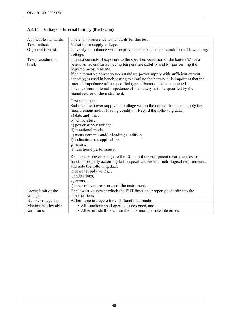
OIML R 139: 2007 (E)
45
A.4.14 Voltage of internal battery (if relevant) Applicable standards: There is no reference to standards for this test. Test method: Variation in supply voltage. Object of the test: To verify compliance with the provisions in 5.1.1 under conditions of low battery
voltage. Test procedure in brief:
The test consists of exposure to the specified condition of the battery(s) for a period sufficient for achieving temperature stability and for performing the required measurements. If an alternative power source (standard power supply with sufficient current capacity) is used in bench testing to simulate the battery, it is important that the internal impedance of the specified type of battery also be simulated. The maximum internal impedance of the battery is to be specified by the manufacturer of the instrument. Test sequence: Stabilize the power supply at a voltage within the defined limits and apply the measurement and/or loading condition. Record the following data: a) date and time, b) temperature, c) power supply voltage, d) functional mode, e) measurements and/or loading condition, f) indications (as applicable), g) errors, h) functional performance. Reduce the power voltage to the EUT until the equipment clearly ceases to function properly according to the specifications and metrological requirements, and note the following data: i) power supply voltage, j) indications, k) errors, l) other relevant responses of the instrument.
Lower limit of the voltage:
The lowest voltage at which the EUT functions properly according to the specifications.
Number of cycles: At least one test cycle for each functional mode Maximum allowable variations:
All functions shall operate as designed, and All errors shall be within the maximum permissible errors.

OIML R 139: 2007 (E)
46
Annex B (Mandatory)
Basic test methods
Preliminary note:
In general, the major factors affecting the accuracy of compressed gaseous fuel (CGF) measuring systems are:
meter sizing suitable for the maximum flow obtainable with the refueling system to which it is fitted. The effect of meter undersizing will be revealed by testing which reaches the measuring system’s specified maximum allowable flow capacity. (The high flow rates occur at the beginning of the refueling and just after each bank switching),
whether the fill is a large one or a small one,
the relative contribution of the low flow rate portions to the total gas quantity delivered in a refueling transaction. (The larger the low flowrate portions the poorer the meter accuracy will likely be. The low flow rate portions are those prior to bank switching and at the very end of refueling),
the shocks, flow acceleration and deceleration resulting from the action of the sequential control device.
The tests specified below take those points into account.
B.1 Test setup
B.1.1 The indicative volumes of the test receiver (representing the vehicle fuel storage system) are:
a) 90 L minimum for testing "low capacity" meters (up to 30 kg/min).
However, 50 L may be accepted provided the test volumes fulfill the appropriate provisions specified in this Recommendation (at least 1000 scale intervals).
b) 300 L minimum for "medium capacity" meters (from 30 kg/min to 70 kg/min).
c) 600 L minimum for "high capacity" meters (above 70 kg/min).
Pipework and valves used on the test receiver shall be adequately sized, at least equivalent to those normally used on the class of vehicles for which the measuring system is intended. In this context "low capacity", "medium capacity" and "high capacity" meters are intended for the refueling of light duty (e.g. cars), medium duty (e.g. medium trucks) and heavy duty (e.g. large trucks and buses) vehicles respectively.
B.1.2 The test reservoir (representing the refueling station fuel storage system) shall be capable of supplying gas at a pressure Pv (the maximum allowable vehicle fast fill pressure) at the end of the test. Indicative volumes are:
a) 800 L for low capacity meter tests,
b) 1600 L for medium capacity meter tests,
c) 2400L for high capacity meter tests.
In each flow test, in conjunction with requirement B.1.4 below, the actual test reservoir volume(s) used shall ensure that, within the last 20 seconds of filling, the test flowrate drops to 120 % of the specified minimum flowrate or less of the meter or of the measuring system. To comply with this, in certain test conditions it may be necessary, before testing starts, to adjust the reservoir volume, i.e. by closing some valves on the test reservoir cylinders.

OIML R 139: 2007 (E)
47
In cases where a sequential control device is used, this requirement applies to the high (last) bank (refer to B.1.4).
The above provision does not apply where the meter or the measuring system is designed to stop below Qmin and where the test is conducted until stopping the flow.
Information of the actual test reservoir volume used in the approval tests shall be made available on the type approval certificate to assist personnel performing the subsequent verifications.
Note: Without this last test reservoir volume criterion it would be possible for the flow test to end at a flow rate significantly higher than the specified minimum measuring system flowrate, thus missing the possible poor meter performance at the low flows.
B.1.3 The pipework and valving of the test rig shall be sized such that the flow capacity of the meter or measuring system will not be reduced when connected to the test rig. In addition, unless otherwise agreed to by the measuring system’s manufacturer, the test rig’s control system shall be such that the maximum gas flowrate obtainable during testing will not exceed the measuring system’s specified maximum allowable gas flowrate.
B.1.4 Where relevant (see B.2.2), the test reservoir volume shall be divided into 3 segments, with a recommended volume ratio of 2:1:1 for the low bank, medium bank and high bank respectively. The test rig shall include a refueling sequential control device, piping and valving suitable for producing the specified maximum and minimum flowrates of the measuring system.
Notes: 1) A common test rig may be possible for many meter sizes (flow capacities), with necessary adjustments or changes in the test rig configuration.
2) The receiver volumes have been selected to reasonably represent a range of on-board CGF storage sizes for light duty, medium duty and heavy-duty vehicles, together with the need to minimize test equipment for cost and handling reasons.
3) The ratio of the test reservoir bank volumes is “typical” of many real life refueling systems which achieve reasonably high station storage utilization.
B.1.5 Gases other than the one intended to be measured may be used for testing providing they do not influence the judgment on measuring results. If necessary, corrections shall be applied.
For Coriolis mass flow meters, nitrogen may be used instead of natural gas without corrections.
B.2 Types of measuring systems and tests
For the purpose of tests, three types of measuring systems are considered:
a) measuring systems utilizing a sequential control device of a refueling station,
b) measuring systems that already incorporate their own sequential control device,
c) measuring systems for refueling stations not utilizing a sequential control device.
The sequential control device of the test rig shall not be used for testing measuring systems of types b and c.
The following test program is appropriate for current technologies and would require adaptation in case of new technology where relevant.
With the exception of the constant flowrate tests, in all the following tests the pressure shall be Pv (the maximum allowable vehicle fast fill pressure) at the end in the test receiver.
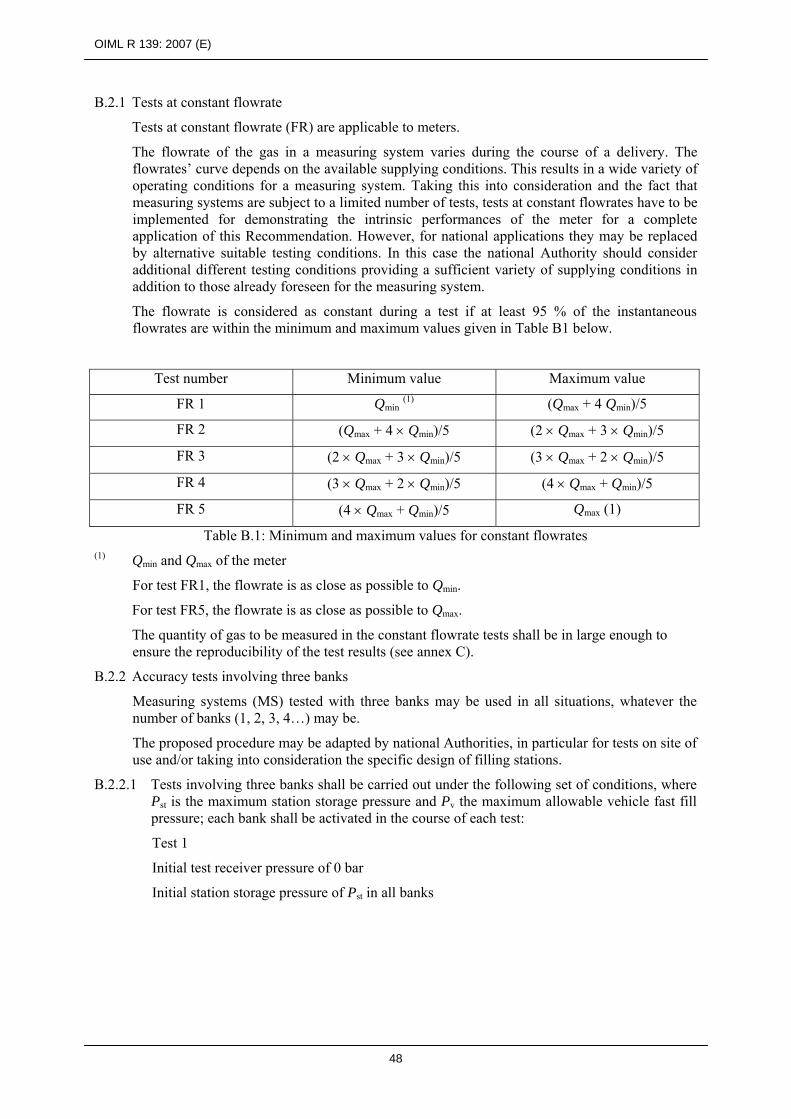
OIML R 139: 2007 (E)
48
B.2.1 Tests at constant flowrate
Tests at constant flowrate (FR) are applicable to meters.
The flowrate of the gas in a measuring system varies during the course of a delivery. The flowrates’ curve depends on the available supplying conditions. This results in a wide variety of operating conditions for a measuring system. Taking this into consideration and the fact that measuring systems are subject to a limited number of tests, tests at constant flowrates have to be implemented for demonstrating the intrinsic performances of the meter for a complete application of this Recommendation. However, for national applications they may be replaced by alternative suitable testing conditions. In this case the national Authority should consider additional different testing conditions providing a sufficient variety of supplying conditions in addition to those already foreseen for the measuring system.
The flowrate is considered as constant during a test if at least 95 % of the instantaneous flowrates are within the minimum and maximum values given in Table B1 below.
Test number Minimum value Maximum value
FR 1 Qmin (1) (Qmax + 4 Qmin)/5
FR 2 (Qmax + 4 × Qmin)/5 (2 × Qmax + 3 × Qmin)/5
FR 3 (2 × Qmax + 3 × Qmin)/5 (3 × Qmax + 2 × Qmin)/5
FR 4 (3 × Qmax + 2 × Qmin)/5 (4 × Qmax + Qmin)/5
FR 5 (4 × Qmax + Qmin)/5 Qmax (1)
Table B.1: Minimum and maximum values for constant flowrates (1) Qmin and Qmax of the meter
For test FR1, the flowrate is as close as possible to Qmin.
For test FR5, the flowrate is as close as possible to Qmax.
The quantity of gas to be measured in the constant flowrate tests shall be in large enough to ensure the reproducibility of the test results (see annex C).
B.2.2 Accuracy tests involving three banks
Measuring systems (MS) tested with three banks may be used in all situations, whatever the number of banks (1, 2, 3, 4…) may be.
The proposed procedure may be adapted by national Authorities, in particular for tests on site of use and/or taking into consideration the specific design of filling stations.
B.2.2.1 Tests involving three banks shall be carried out under the following set of conditions, where Pst is the maximum station storage pressure and Pv the maximum allowable vehicle fast fill pressure; each bank shall be activated in the course of each test:
Test 1
Initial test receiver pressure of 0 bar
Initial station storage pressure of Pst in all banks

OIML R 139: 2007 (E)
49
Test 2
Initial test receiver pressure of 0.5 × Pv
Initial station storage pressure:
- high bank at Pst, - medium bank at close to Pv, - low bank at 0.75 × Pv.
Test 3
Initial test receiver pressure of 0.75 × Pv
Initial station storage pressure: - high bank at Pst, - medium bank at close to Pv, - low bank at 0.75 × Pv.
B.2.2.2 The bank volumes shall be such that refueling into the specified test cylinders will cause the activation of all stages of the operation of the refueling sequential control device. Where a sequential control device is not included in a MS, it shall complete the switching action from one bank to another within 3 s. Where a sequential control device is included in an MS, it shall complete the switching action from one bank to another within the minimum possible delay as designed by the manufacturer (if relevant). Where relevant the maximum allowed speed (the tested one) shall be specified in the type approval certificate.
The test receiver volume and test reservoir volume and their storage bank volume ratio shall be as specified in B.1.1, B.1.2 and B.1.4. It may be necessary to close some valves on the test reservoir cylinders to achieve the required test reservoir volume and bank proportions.
B.2.3 Accuracy tests involving only one bank
Tests without sequential controls shall be performed in the following conditions:
Test 4
Initial test receiver pressure of 0 bar Initial station storage pressure at Pst
Test 5
Initial test receiver pressure of 0.5 × Pv Initial station storage pressure at Pst
Test 6
Initial test receiver pressure of 0.75 × Pv Initial station storage pressure at Pst
Test 7 (minimum measured quantity)
The conditions for test 6 are adapted in order to test the minimum measured quantity. For this purpose, the pressure does not have to be Pv in the test receiver at the end, but may be any pressure (as close as practical to Pv) such that the quantity of transferred gas shall be at least the minimum measured quantity.
For tests without bank switching, the test reservoir pipework can simply be changed so that all test reservoir cylinder banks are joined together, i.e. there are no high, medium or low banks; the reservoir in this case is a uniform station storage pressure system.
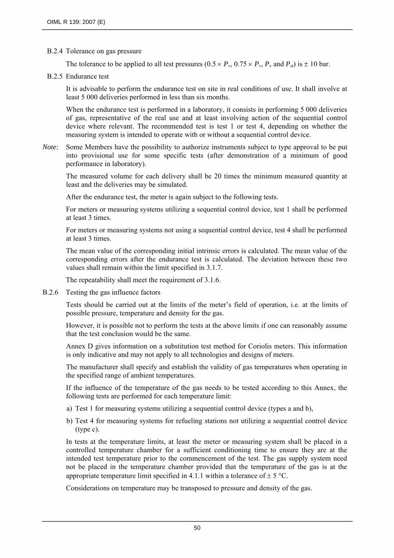
OIML R 139: 2007 (E)
50
B.2.4 Tolerance on gas pressure
The tolerance to be applied to all test pressures (0.5 × Pv, 0.75 × Pv, Pv and Pst) is ± 10 bar.
B.2.5 Endurance test
It is advisable to perform the endurance test on site in real conditions of use. It shall involve at least 5 000 deliveries performed in less than six months.
When the endurance test is performed in a laboratory, it consists in performing 5 000 deliveries of gas, representative of the real use and at least involving action of the sequential control device where relevant. The recommended test is test 1 or test 4, depending on whether the measuring system is intended to operate with or without a sequential control device.
Note: Some Members have the possibility to authorize instruments subject to type approval to be put into provisional use for some specific tests (after demonstration of a minimum of good performance in laboratory). The measured volume for each delivery shall be 20 times the minimum measured quantity at least and the deliveries may be simulated.
After the endurance test, the meter is again subject to the following tests.
For meters or measuring systems utilizing a sequential control device, test 1 shall be performed at least 3 times.
For meters or measuring systems not using a sequential control device, test 4 shall be performed at least 3 times.
The mean value of the corresponding initial intrinsic errors is calculated. The mean value of the corresponding errors after the endurance test is calculated. The deviation between these two values shall remain within the limit specified in 3.1.7.
The repeatability shall meet the requirement of 3.1.6.
B.2.6 Testing the gas influence factors
Tests should be carried out at the limits of the meter’s field of operation, i.e. at the limits of possible pressure, temperature and density for the gas.
However, it is possible not to perform the tests at the above limits if one can reasonably assume that the test conclusion would be the same.
Annex D gives information on a substitution test method for Coriolis meters. This information is only indicative and may not apply to all technologies and designs of meters.
The manufacturer shall specify and establish the validity of gas temperatures when operating in the specified range of ambient temperatures.
If the influence of the temperature of the gas needs to be tested according to this Annex, the following tests are performed for each temperature limit:
a) Test 1 for measuring systems utilizing a sequential control device (types a and b),
b) Test 4 for measuring systems for refueling stations not utilizing a sequential control device (type c).
In tests at the temperature limits, at least the meter or measuring system shall be placed in a controlled temperature chamber for a sufficient conditioning time to ensure they are at the intended test temperature prior to the commencement of the test. The gas supply system need not be placed in the temperature chamber provided that the temperature of the gas is at the appropriate temperature limit specified in 4.1.1 within a tolerance of ± 5 °C.
Considerations on temperature may be transposed to pressure and density of the gas.

OIML R 139: 2007 (E)
51
B.2.7 Specific tests
If they are critical the following tests shall also be carried out:
determination of the periodic variation, tests with flow disturbances.
For tests with flow disturbances, the applicable maximum permissible errors are those specified for the measuring system and not those fixed for the meter. These tests are performed in accordance with the state of the art (see in particular OIML D 7 [5], OIML R 137-1 [7] and relevant ISO Standards), taking into consideration:
flow disturbances existing in real life refueling station equipment, design of meters and measuring systems, circumstances which are known to affect their performances.
B.3 Type approval tests
Table B.2 summarizes the required type approval tests for various meter and measuring systems according to their configuration, i.e. whether they are used in conjunction with a sequential control system. (Note: 2× = two times, 3× = three times)
Table B.2
Test
name/number All meters
Meter intended for use with
sequential control
Measuring system for use with sequential
control
Measuring system with adjustable sequential
control (test at extreme
adjustment limits)
Measuring system for use
without sequential
control
Test with constant flowrates
FR1
FR2
FR3
FR4
FR5
3×
3×
3×
3×
Tests with sequential
control
Test 1
Test 2
Test 3
Optional, 3×
Mandatory, 3×
Mandatory, 3×
Mandatory, 3×
3×
Tests without sequential
control
Test 4
Test 5
3×
3×
3×
3×

OIML R 139: 2007 (E)
52
Test
name/number All meters
Meter intended for use with
sequential control
Measuring system for use with sequential
control
Measuring system with adjustable sequential
control (test at extreme
adjustment limits)
Measuring system for use
without sequential
control
Test 6
Test 7
2×
3×
2×
Endurance 5 000 deliveries
in 6 months
Gas influence factors
2 × per type of factor
Flow disturbances
etc.
Optional,
2×
2× if not already
done on meter
2× if not already done
on meter
Some tests may be performed on site provided that it is possible to assume that test results would be equivalent if they were performed in reference conditions.
B.3.1 Meter
B.3.1.1 General considerations
According to the request of the manufacturer, a type approval may be granted for a meter alone or any sub-assembly including a meter. However, the test program applicable to meters is performed whether or not type approval for the meter is requested.
In principle, the meter is tested alone. However, it can be tested in any sub-assembly or a complete measuring system provided it is possible to assume that test results would be equivalent if they were performed on the meter alone.
B.3.1.2 Test program
1. Tests FR 1 to FR 5 (see B.2.1) shall be performed at least 3 times consecutively in the same conditions in order to establish the intrinsic behavior of the meter.
Each individual error shall conform to the MPEs specified in 3.1.1 for the meter.
The requirement on repeatability specified in 3.1.5 shall be fulfilled.
2. Tests 4 and 5 (see B.2.3) shall be performed at least 3 times consecutively in the same conditions in order to establish the dynamic behavior of the meter.
Each individual error shall conform to the MPEs specified in 3.1.1 for the meter.
The requirement on repeatability specified in 3.1.6 shall be fulfilled.
3. The endurance test (see B.2.5) shall be performed.
If the meter is intended to be included in a measuring system utilizing a sequential control device, the test shall be performed so that the meter operates in conjunction with such a device.
In the case of a meter accompanied with a particular sequential control device, this particular device shall be subject to the test associated with the meter. In the case where

OIML R 139: 2007 (E)
53
the result could be dependent on the type of sequential control device (whether it is included in a measuring system) and according to the manufacturer’s specifications, the device providing the most severe flow switching effects shall be used. Any appropriate information shall be indicated in the type approval certificate.
The requirement on endurance specified in 3.1.7 shall be fulfilled and the requirement on repeatability shall be fulfilled.
4. If applicable (see Annex D) tests on gas influence factors (see B.2.6) shall be performed.
If applicable each test shall be performed twice.
If the corresponding tests are not performed reason shall be given in the test report.
Each individual error shall be conforming to the MPEs specified in 3.1.1 for the meter.
5. If the meter is intended to be included in a measuring system utilizing a sequential control device, on demand of the manufacturer, test 2 (see B.2.2) may be performed at least 3 times consecutively in the same conditions.
The corresponding information is laid down in the type approval certificate.
Each individual error shall conform to the MPEs specified in 3.1.1 for the meter.
The requirement on repeatability specified in 3.1.6 shall be fulfilled.
6. On demand of the manufacturer, appropriate specific tests (see B.2.7) may be performed.
If applicable each test shall be performed twice.
The corresponding information is laid down in the type approval certificate.
Each individual error shall conform to the MPEs specified in 3.1.1 for the meter.
B.3.2 Measuring systems utilizing a sequential control device (type a and type b)
1. Tests 1, 2, 3 shall be performed on the complete system at least 3 times consecutively in the same conditions.
Each individual error shall conform to the MPEs specified in 3.1.1 for the measuring system.
The requirement on repeatability specified in 3.1.6 shall be fulfilled.
2. Test 7 shall be performed on the complete system at least twice.
Each individual error shall conform to the MPEs specified in 3.1.3 for the measuring system.
3. If relevant and not already performed on the meter, specific tests (see B.2.7) are performed.
If applicable each test shall be performed twice.
Each individual error shall conform to the MPEs specified in 3.1.1 for the measuring system.
4. For measuring systems that may be used with a sequential control device (incorporated or not) fitted with adjustment parameters, test 1 shall be performed at least 3 times consecutively in the same conditions for each extreme value of the adjustment parameters. When a parameter is tested, other parameters are at reference condition as specified by the manufacturer.
Each individual error shall be conforming to the MPEs specified in 3.1.1 for the measuring system.
The requirement on repeatability specified in 3.1.6 shall be fulfilled.
B.3.3 Measuring systems for refueling stations not utilizing a sequential control device
1. Tests 4, 5, 6 shall be performed on the complete system at least 3 times consecutively in the

OIML R 139: 2007 (E)
54
same conditions.
Each individual error shall conform to the MPEs specified in 3.1.1 for the measuring system.
The requirement on repeatability specified in 3.1.6 shall be fulfilled.
2. Test 7 shall be performed on the complete system at least twice.
Each individual error shall conform to the MPEs specified in 3.1.3 for the measuring system.
3. If relevant and not already performed on the meter, specific tests (see B.2.7) are performed.
If applicable each test shall be performed twice.
Each individual error shall conform to the MPEs specified in 3.1.1 for the measuring system.
B.3.4 Specific provisions
When it is intended to perform initial verification of the meter or of the system with a fluid other than the gas or gases to be measured or only with one gas when the system is intended to measure two or more gases, specific tests shall be performed in order to determine appropriate shift and/or reduction of maximum permissible errors as indicated in 3.2.2.
In general this determination should involve more than one meter in order to consider the reproducibility of the type of meter depending on individual meters.
The provisions in this paragraph shall be implemented so that it can be assumed that the measuring systems in use respect maximum permissible errors with the intended gas or all the gases. The shifted and/or reduced maximum permissible errors are established taking into consideration the reproducibility of the type of meter or measuring system.
B.4 Tests at initial verification
Ideally the testing procedure is specified is B.4.1. However the national Authority may authorize the practical procedure specified in B.4.2.
B.4.1 Theoretical procedure
B.4.1.1 The initial verification shall include at least:
for all measuring systems, one test in any one possible condition available in the refueling station, provided that if applicable, the bank pressures shall be such that refueling into the specified test cylinders will cause the activation of all stages of the operation of the sequential control device,
for measuring systems for refueling stations utilizing the sequential control device of a refueling station or systems that incorporate their own sequential control device, one test corresponding as far as possible to test 1 (test 3 may also be considered),
for testing measuring systems that do not incorporate their own sequential control device or that are to be used in refueling stations not using a sequential control device, one test corresponding as far as possible to test 4 (test 6 may also be considered).
The type approval certificate may provide for more the tests to be performed.
B.4.1.2 At least one of the tests should be performed on site in the real refueling station. Test 1 (and/or test 3) or test 4 (and/or test 6), depending on the case, may be performed in the laboratory.
The test conditions shall be such that:
the maximum flowrate available in the particular refueling station for the particular measuring system shall be reached,

OIML R 139: 2007 (E)
55
the maximum flowrate available in the particular refueling station for the particular measuring system shall be smaller than or equal to the specified maximum permissible flowrate of the measuring system,
the test conditions specified in B.1.1, B.1.2 and where relevant B.1.4 shall be met,
the sequential control action of the real life system shall be no faster than that used in the laboratory.
B.4.1.3 The tests at initial verification are performed at ambient temperature within rated operating conditions.
Each applicable test is performed twice.
Each individual error shall fulfill the requirement on MPEs specified in 3.1.1 or 3.1.2, depending on whether the verification is done on site or in the laboratory.
B.4.2 Practical procedure
The tests are performed in conditions available in the refueling station, provided that, if applicable, the bank pressures shall be such that refueling into the specified test cylinders will cause the activation of all stages of the operation of the sequential control device.
The test conditions shall be such that the maximum observed flowrate during the tests is no less than 80 % of theoretical maximum flowrate available in the particular refueling station for the particular measuring system.
It shall be checked by design that the theoretical maximum flowrate available in the particular refueling station for the particular measuring system is smaller than or equal to the specified maximum permissible flowrate of the measuring system.
The tests at initial verification are performed at ambient temperature within rated operating conditions.
Tests sufficiently representative of real conditions of use are performed. In general this condition is supposed to be fulfilled with the following sequence:
filling the test receiver from empty to Pv,
venting the test receiver to a pressure of 0.5 × Pv,
re-filling the test receiver from 0.5 × Pv to Pv.
This sequence provides two metrological results to be compared with the MPEs. Each applicable test is performed at least twice and as far as necessary to fulfill the requirement in the first paragraph of this subclause.
Each individual error shall fulfill the requirement on MPEs specified in 3.1.2.
The type approval certificate may provide for more information on the tests to be performed.
B.5 Subsequent verifications
The policy for testing at subsequent verifications is left to the national Authority.
Subsequent verifications should be performed on site and may be identical to initial verification.

OIML R 139: 2007 (E)
56
Annex C (Informative)
Minimum test quantities
for measuring systems and devices Provided that it can be assumed that the largest uncertainty component is due to the rounding of the digital scale interval s, the following may be considered. In case of a digital scale interval s and determination of errors of a meter it can be demonstrated that the distribution law is triangular and that the standard uncertainty us is:
With a coverage factor equal to 2, the expanded corresponding uncertainty U is:
U = 2 × us The requirement on uncertainty at type approval compared to the tolerance T is:
5TU ≤
That is:
Ts≤
×
610
1) Case of determining the error for a complete measuring system with MPE = ± 1.5 %
T = MPE = 1.5 × 10⁻² × Q The quantity Q is:
Q = n × s Where n is the number of scale intervals. This leads to:
sns××≤
× 015.06
10
That is:
16.27265.1
1000=≥n
Rounded to 273≥n
6ssu =
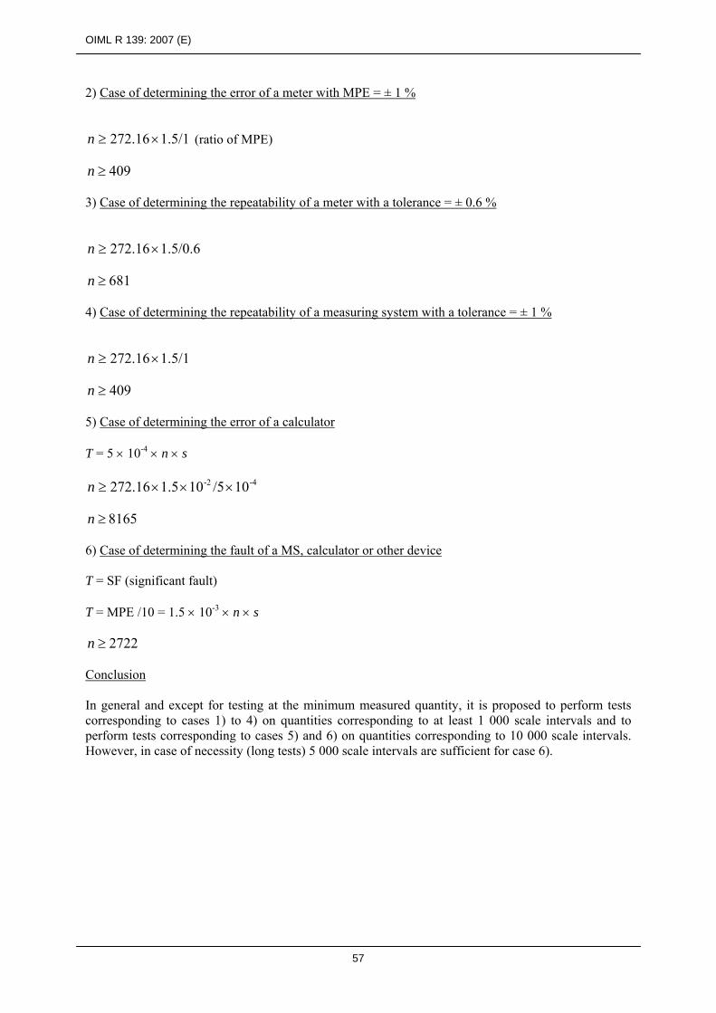
OIML R 139: 2007 (E)
57
2) Case of determining the error of a meter with MPE = ± 1 %
1.5/1 272.16×≥n (ratio of MPE)
409≥n
3) Case of determining the repeatability of a meter with a tolerance = ± 0.6 %
1.5/0.6 272.16×≥n
681≥n
4) Case of determining the repeatability of a measuring system with a tolerance = ± 1 %
1.5/1 272.16×≥n
409≥n
5) Case of determining the error of a calculator T = 5 × 10⁻⁴ × n × s
-4-2 10 /510 1.5 272.16 ×××≥n
8165≥n
6) Case of determining the fault of a MS, calculator or other device T = SF (significant fault) T = MPE /10 = 1.5 × 10⁻³ × n × s
2722≥n
Conclusion In general and except for testing at the minimum measured quantity, it is proposed to perform tests corresponding to cases 1) to 4) on quantities corresponding to at least 1 000 scale intervals and to perform tests corresponding to cases 5) and 6) on quantities corresponding to 10 000 scale intervals. However, in case of necessity (long tests) 5 000 scale intervals are sufficient for case 6).
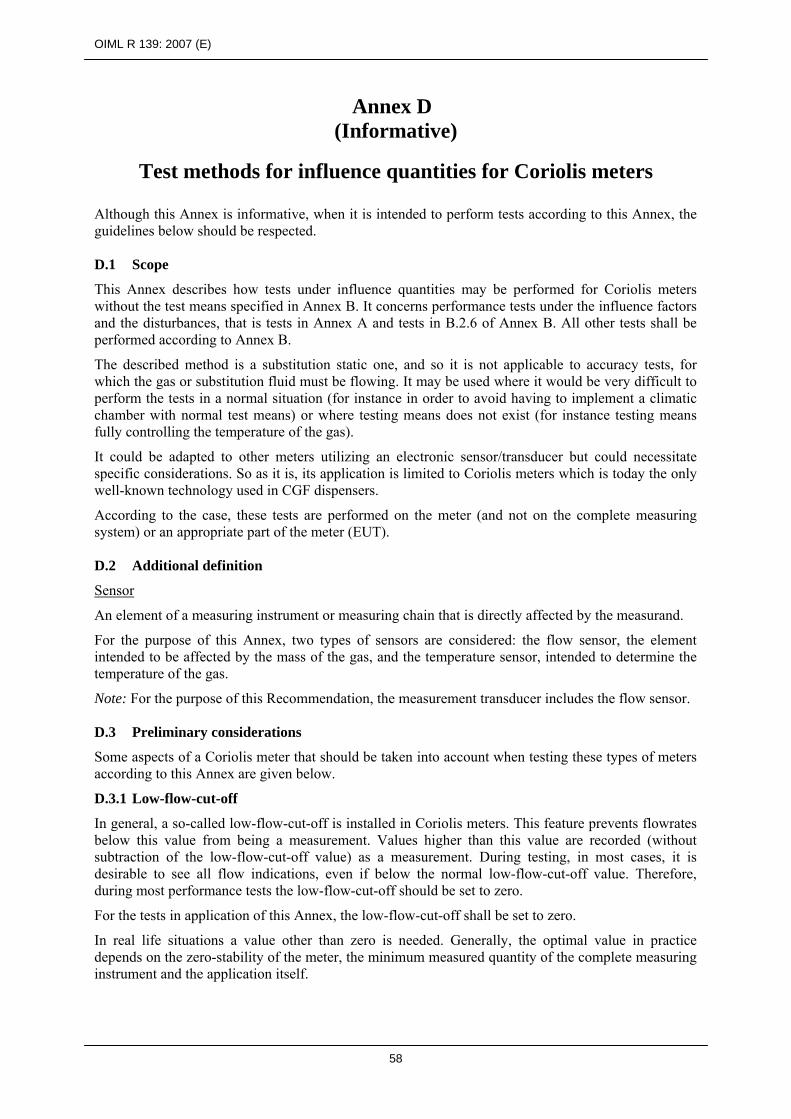
OIML R 139: 2007 (E)
58
Annex D (Informative)
Test methods for influence quantities for Coriolis meters Although this Annex is informative, when it is intended to perform tests according to this Annex, the guidelines below should be respected. D.1 Scope
This Annex describes how tests under influence quantities may be performed for Coriolis meters without the test means specified in Annex B. It concerns performance tests under the influence factors and the disturbances, that is tests in Annex A and tests in B.2.6 of Annex B. All other tests shall be performed according to Annex B.
The described method is a substitution static one, and so it is not applicable to accuracy tests, for which the gas or substitution fluid must be flowing. It may be used where it would be very difficult to perform the tests in a normal situation (for instance in order to avoid having to implement a climatic chamber with normal test means) or where testing means does not exist (for instance testing means fully controlling the temperature of the gas).
It could be adapted to other meters utilizing an electronic sensor/transducer but could necessitate specific considerations. So as it is, its application is limited to Coriolis meters which is today the only well-known technology used in CGF dispensers.
According to the case, these tests are performed on the meter (and not on the complete measuring system) or an appropriate part of the meter (EUT). D.2 Additional definition
Sensor
An element of a measuring instrument or measuring chain that is directly affected by the measurand.
For the purpose of this Annex, two types of sensors are considered: the flow sensor, the element intended to be affected by the mass of the gas, and the temperature sensor, intended to determine the temperature of the gas.
Note: For the purpose of this Recommendation, the measurement transducer includes the flow sensor. D.3 Preliminary considerations
Some aspects of a Coriolis meter that should be taken into account when testing these types of meters according to this Annex are given below.
D.3.1 Low-flow-cut-off
In general, a so-called low-flow-cut-off is installed in Coriolis meters. This feature prevents flowrates below this value from being a measurement. Values higher than this value are recorded (without subtraction of the low-flow-cut-off value) as a measurement. During testing, in most cases, it is desirable to see all flow indications, even if below the normal low-flow-cut-off value. Therefore, during most performance tests the low-flow-cut-off should be set to zero.
For the tests in application of this Annex, the low-flow-cut-off shall be set to zero.
In real life situations a value other than zero is needed. Generally, the optimal value in practice depends on the zero-stability of the meter, the minimum measured quantity of the complete measuring instrument and the application itself.

OIML R 139: 2007 (E)
59
D.3.2 No-flow conditions
Typically, Coriolis meters measure continuously. Under no-flow conditions the same processes are carried out as under flow conditions. So, for the meter it makes little difference whether there is flow or not.
D.3.3 Temperature measurement
Most Coriolis meters are equipped with an internal temperature sensor for the purpose of correction. When this is the case, the meter shall be tested with the temperature measurement function activated.
D.3.4 Pressure measurement
Pressure transmitters may be connected to a Coriolis meter for various purposes. When this is the case, the meter shall be tested with the pressure measurement function activated.
D.3.5 Warm up time
All Coriolis meters use electronics, which are partly analog. Because the characteristics of analog components are temperature dependent, the device’s characteristics are only stable when the electronics have reached a stable temperature. The test shall be performed at conditions representative of the warming time of the meter in the complete measuring system.
D.3.6 Coriolis sensor
All Coriolis meters known at this time, consist basically of two sensors: one flow sensor (usually consisting of one or two parallel measurement tubes) and a temperature sensor for the benefit of performing temperature corrections on the vibrational properties of the flow sensor.
The primary measurement signals of a Coriolis meter are the following:
a time difference related to the mass flowrate through the flow sensor a resonant frequency related to the density of the gas in the flow sensor a resistance related to the temperature of the measurement tube(s)
The measurement tube(s) is/are set into motion (a sinusoidal vibration) by means of an alternating current through one or more so-called drive coils. The movement of the measurement tubes is detected using at least two pick-off coils. In principle these coils are considered to be electronic components, thus making a Coriolis flow sensor an electronic device, on which the applicable performance tests need to be performed.
As stated above, usually a temperature sensor is implemented to be able to perform corrections on the flow signals. A vibrating tube becomes more or less stiff, depending on its temperature. As a consequence of this purely mechanical phenomenon, the temperature of the measurement tubes affects the primary signals for mass and density.
Performance tests, including tests on climatic effects, are carried out to verify that electronic devices (or components thereof) operate within their maximum permissible errors over their rated operating conditions. In the case of Coriolis sensors, two separate effects can occur as a consequence of changing temperatures: A mechanical effect due to the changing vibrational properties of the measurement tubes and an effect on the device’s electronics. Application of the test condition, in this case ambient temperature, will lead to two separate effects on the Coriolis flow sensor. Knowing the original purpose of the performance tests, it may be necessary to observe these two effects separately.
Consequently, even if some parts of the flow sensor may be considered as mechanical components, they need to be subjected to the influence of gas temperature in accordance with B.2.6 (see D.4.6).

OIML R 139: 2007 (E)
60
D.3.7 Coriolis transducer
An electronic device which processes the primary analog measurement signals is connected to the sensors. These signals are subsequently processed by a calculating device and sent to outputs such as an indicating device and/or to the (main) calculator. Before the mass flowrate can be determined, two important calculations are performed: a correction calculation based on the temperature of the measurement tubes and the adjustment for the zero-setting of the device (see D.3.8).
D.3.8 Zero-setting
The vibrational properties of a Coriolis flow sensor are mainly determined by the way of installation, changes in temperature and changes in density. Because a Coriolis meter continuously processes its signals, also under no-flow conditions, any time difference between the signals of the pick-off coils is processed into a mass flowrate. Depending on the properties of the measurement tubes and the stresses on the tubes caused by the installation, also under no-flow conditions a mass flowrate may be observed. The observed mass flowrate under no-flow conditions is known as the zero-flow. The zero-flow is determined by the EUT after input of special commands. This value (which can be a positive or negative mass flowrate) is stored and memorized in the Coriolis transducer and subtracted from/added to all the flow rate values determined by the transducer. D.4 Test methods D.4.1 Categories of test methods for influence factors at type evaluation
The tests can be divided into three categories:
tests under (environmental) influence factors in Annex A,
tests under disturbances in Annex A,
tests under the gas influence factors (B.2.6).
For each of these categories, specific information on the test method is given. However, the same general principle applies.
D.4.2 General principle
All performance tests applicable to a certain EUT are performed one after another in one series of tests. Before the series of tests, the EUT’s performance under reference conditions is verified. For each influence quantity, another test is then performed during the application of the quantity or after its application, according to what is appropriate. In case of an effective influence, a change in flowrate (CF) is observed.
For tests defined in Annex A, a virtual flow signal is created by implementing a systematic offset to obtain a flowrate as close as possible to Qmin. The implementation of this offset must allow the detection of the disturbance effects on the electronic components of the sensors (including the coils). If this is not the case, the method described below for the application of B.2.6 should be considered.
For application of B.2.6, the actual signal at zero flow is considered. For this purpose the low-flow-cut-off is set to zero.
For each influence quantity CF is recorded and the relative influence (RCF) is determined using the following formula:
RCF (%) = CF / Qmin × 100
Note: For application of B.2.6, RCF decreases with an increasing flowrate and a reference to the minimum flowrate in the formula provides the most severe criterion.
The value of RCF shall be smaller than the applicable MPE or the significant fault, according to the case.

OIML R 139: 2007 (E)
61
During each measurement, the flowrate of the meter is monitored. One immediately obtains information on the stability of the device. For the measurement under reference conditions, the flowrate should be stable. For some tests under influence quantities the flowrate may fluctuate. As a general principle, the flowrate taken into consideration should be that corresponding to the maximum change. However, it is possible to use a flowrate that is more representative of the actual accuracy if it can be assumed that the flowrates providing larger changes are purely transitory phenomenon which can not lead to inaccurate measurements.
D.4.3 Before starting tests
To prevent damage to the flow sensor due to temperature expansion or contraction, except where necessary, do not close the flow sensor by means of rigid blinding flanges.
Before the temperature of the gas is fully stabilized, temperature convection will cause small flows of gas to move up and down through the EUT. On some meters this will appear as a flow indication where none is expected.
D.4.4 Specific aspects of the test method for influence factors
The object of an influence factor test is to verify that the EUT operates within its maximum permissible errors.
For ambient temperature tests, it should be possible to test the effects on the EUT's electronics separately when the mechanical effect due to changing the temperature of the tube can be eliminated. When one pick-off coil is connected in parallel to both applicable inputs, the mechanical effect of temperature changes is eliminated, whereas an effect on the electronics is still observed.
Where the effect of the influence factor on the mechanical parts of the EUT can be eliminated, the MPEs specified for the calculator in 4.8 apply.
Where the effect of the influence factor on the mechanical parts of the EUT cannot be eliminated, the MPEs specified for the meter in 3.1.1 apply.
D.4.5 Specific aspects of the test method for disturbances
In any case the significant fault applies.
D.4.6 Specific aspects of the test method for the gas influence factors
The complete flow sensor shall be used in the test; the applicable MPEs are those specified for the meter. The temperature correction shall be active and operating in the same manner as during normal measurements.
If it is not possible to heat or to cool the temperature of the gas inside the flow sensor to the required temperatures, the complete flow sensor may be put in the temperature chamber. The measurements are performed when the temperature inside the flow sensor is stabilized at the temperature limits (Tmax and Tmin) of the rated operating conditions for the temperature of the gas specified by the manufacturer.
For the test under the influence of pressure, the flanges closing the flow sensor shall be rigid enough so that the pressure limits (max and min) of the rated operating conditions for the pressure of the gas specified by the manufacturer may be reached.
When it is considered appropriate to test the meter according to the nature or density of the gas, the reference gas is that specified by the manufacturer.
OIML R 139: 2007 (E)
62
Bibliography
[1] International vocabulary of metrology - Basic and general concepts and associated terms (VIM), 2007
[2] International vocabulary of terms in legal metrology (VIML). OIML, Paris, 2000 [3] The International System of Units (SI), 8th edition, BIPM, Paris, 2006 [4] International Document OIML D 2: Legal units of measurement, OIML, Paris,
2007 [5] International Document OIML D 7: The evaluation of flow standards and facilities
used for testing water meters, OIML, Paris, 1984 [6] International Document OIML D 11: General requirements for electronic
measuring instruments, OIML, Paris, 2004 [7] International Recommendation OIML R 137-1: Gas Meters. Part 1: Requirements,
OIML, Paris, 2006 [8] Guide to the expression of uncertainty in measurement (GUM). BIPM, IEC, IFCC,
ISO, IUPAC, IUPAP and OIML. ISO, Geneva, 1995 [9] IEC 60068-2-1 (2007-03) Environmental testing, Part2: Tests, Test A: Cold [10] IEC 60068-2-2 (1974-01), with amendments 1 (1993-02) and 2 (1994-05)
Environmental testing Part2: Tests. Test B: Dry heat [11] IEC 60068-2-30 (2005-08) Environmental testing Part 2: Tests. Test Db and
guidance: Damp heat, cyclic (12 + 12-hour cycle) [12] IEC 60068-2-64 (1993-05), with Corrigendum 1(1993-10) Environmental testing –
Part 2: Test methods, Test Fh: Vibration, broad-band random (digital control) and guidance
[13] IEC 60068-3-1 (1974-01) with Supplement 1 (1978-01) Environmental testing, Part 3: Background information, section 1: Cold and dry heat tests
[14] IEC/TR 61000-2-1 (1990-05) Electromagnetic compatibility (EMC) - Part 2: Environment - Section 1: Description of the environment - Electromagnetic environment for low-frequency conducted disturbances and signaling in public power supply systems
[15] IEC 61000-2-2 (2002-03) Electromagnetic compatibility (EMC) - Part 2-2: Environment - Compatibility levels for low-frequency conducted disturbances and signalling in public low-voltage power supply systems
[16] IEC 60654-2 (1979-01) with amendment 1 (1992-09) Operating conditions for industrial-process measurement and control equipment. Part 2: Power
[17] IEC 61000-4-1(2006-10) Electromagnetic compatibility (EMC), Part 4-1: Testing and measurement techniques - Overview of IEC 61000-4 series
[18] IEC 61000-4-2 (2001-04) Electromagnetic compatibility (EMC), Part 4-2: Testing and measurement techniques - Electrostatic discharge immunity test
[19] IEC 61000-4-3 (2006-02) Electromagnetic compatibility (EMC): Part 4-3: Testing and measurement techniques - Radiated, radio-frequency, electromagnetic field immunity test
[20] IEC 61000-4-4 (2004-07) with correction 1 (2006-08) Electromagnetic compatibility (EMC) - Part 4: Testing and measurement techniques - Section 4: Electrical fast transient/burst immunity test. Basic EMC Publication
[21] IEC 61000-4-5 (2005-11) Electromagnetic compatibility (EMC) - Part 4-5: Testing and measurement techniques - Surge immunity test
OIML R 139: 2007 (E)
63
[22] IEC 61000-4-6 (2003-05) with amendment 1 (2004-10) and amendment 2 (2006-03) Electromagnetic compatibility (EMC): Part 4: Testing and measurement techniques, Section 6: Immunity to conducted disturbances, induced by radio-frequency fields. Consolidated Edition: IEC 61000-4-6 (2006-05) Ed. 2.2
[23] IEC 61000-4-11 (2004-03) - Part 4-11: Testing and measuring techniques - Voltage dips, short interruptions and voltage variations immunity tests
[24] IEC 61000-6-1 (2005-03) Electromagnetic compatibility (EMC) - Part 6-1: Generic standards - Section 1: Immunity for residential, commercial and light-industrial environments
[25] IEC 61000-6-2 (2005-01) Electromagnetic compatibility (EMC) - Part 6-2: Generic standards - Immunity for industrial environments