compressed hydrogen2011 11_chato
TRANSCRIPT
NASA Perspectives on Cryo H2 Storage
DOE Hydrogen Storage WorkshopMarriott Crystal Gateway
Arlington, VAFebruary 15, 2011
David J. ChatoNASA Glenn Research Center
Michael P. DohertyNASA Glenn Research Center
2
Objectives
Purposes of this Presentation• To show the role of Cryogenics in NASA prior
missions• To show recent NASA accomplishments in cryogenic
fluid management technology• To highlight the importance of long term cryogenic
storage to future NASA missions (especially Human Space flight)
3
What is Cryogenic Fluid Management?
3
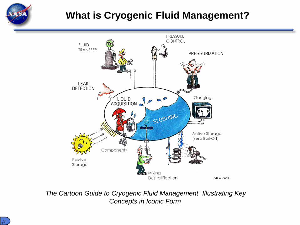
The Cartoon Guide to Cryogenic Fluid Management Illustrating Key Concepts in Iconic Form
4
GRC Cryogenic Fluid Management Accomplishments
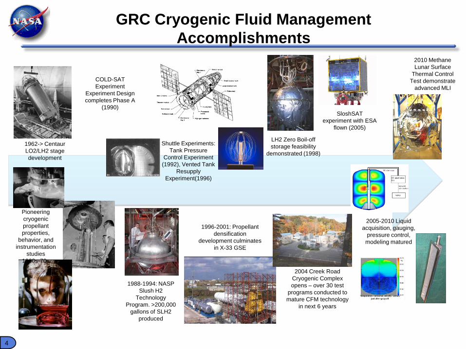
Pioneering cryogenic propellant properties,
behavior, and instrumentation
studies1960s-70s
1962-> Centaur LO2/LH2 stage development
Shuttle Experiments: Tank Pressure
Control Experiment (1992), Vented Tank
Resupply Experiment(1996)
SloshSAT experiment with ESA
flown (2005)
1988-1994: NASP Slush H2
Technology Program. >200,000
gallons of SLH2 produced
1996-2001: Propellant densification
development culminates in X-33 GSE
COLD-SAT Experiment
Experiment Design completes Phase A
(1990)
LH2 Zero Boil-off storage feasibility
demonstrated (1998)
2004 Creek Road Cryogenic Complex opens – over 30 test
programs conducted to mature CFM technology
in next 6 years
2005-2010 Liquid acquisition, gauging,
pressure control, modeling matured
2010 Methane Lunar Surface
Thermal Control Test demonstrate
advanced MLI
5
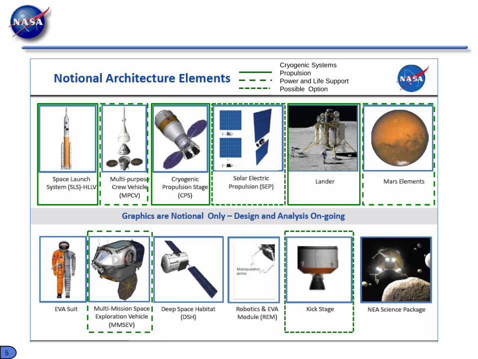
Exploration Systems Mission Directorate --HEFT Elements Need CFM
Cryogenic SystemsPropulsionPower and Life SupportPossible Option
6
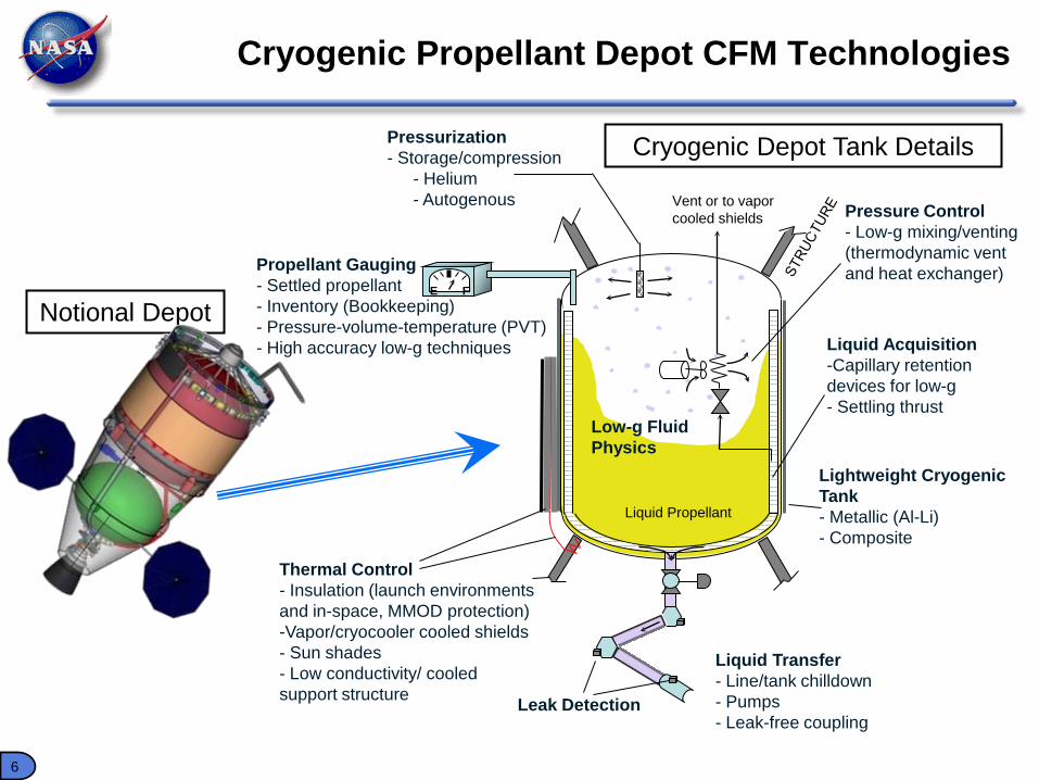
Cryogenic Propellant Depot CFM Technologies
Thermal Control- Insulation (launch environments and in-space, MMOD protection)-Vapor/cryocooler cooled shields- Sun shades- Low conductivity/ cooled support structure
Liquid Acquisition-Capillary retention devices for low-g- Settling thrust
Pressurization- Storage/compression
- Helium- Autogenous Pressure Control
- Low-g mixing/venting (thermodynamic vent and heat exchanger)
Lightweight Cryogenic Tank- Metallic (Al-Li)- Composite
Propellant Gauging- Settled propellant - Inventory (Bookkeeping)- Pressure-volume-temperature (PVT)- High accuracy low-g techniques
Vent or to vapor cooled shields
E F
Liquid Propellant
Notional Depot
Cryogenic Depot Tank Details
Liquid Transfer- Line/tank chilldown- Pumps- Leak-free coupling
Leak Detection
Low-g FluidPhysics
7
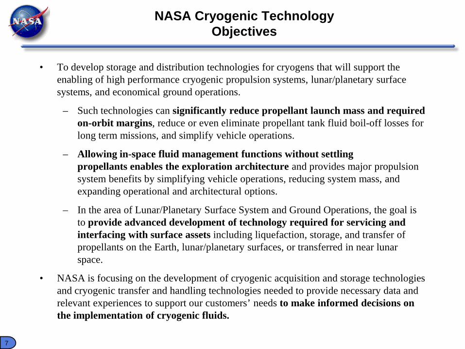
NASA Cryogenic Technology Objectives
• To develop storage and distribution technologies for cryogens that will support the enabling of high performance cryogenic propulsion systems, lunar/planetary surface systems, and economical ground operations.
– Such technologies can significantly reduce propellant launch mass and required on-orbit margins, reduce or even eliminate propellant tank fluid boil-off losses for long term missions, and simplify vehicle operations.
– Allowing in-space fluid management functions without settling propellants enables the exploration architecture and provides major propulsion system benefits by simplifying vehicle operations, reducing system mass, and expanding operational and architectural options.
– In the area of Lunar/Planetary Surface System and Ground Operations, the goal is to provide advanced development of technology required for servicing and interfacing with surface assets including liquefaction, storage, and transfer of propellants on the Earth, lunar/planetary surfaces, or transferred in near lunar space.
• NASA is focusing on the development of cryogenic acquisition and storage technologies and cryogenic transfer and handling technologies needed to provide necessary data and relevant experiences to support our customers’ needs to make informed decisions on the implementation of cryogenic fluids.
888
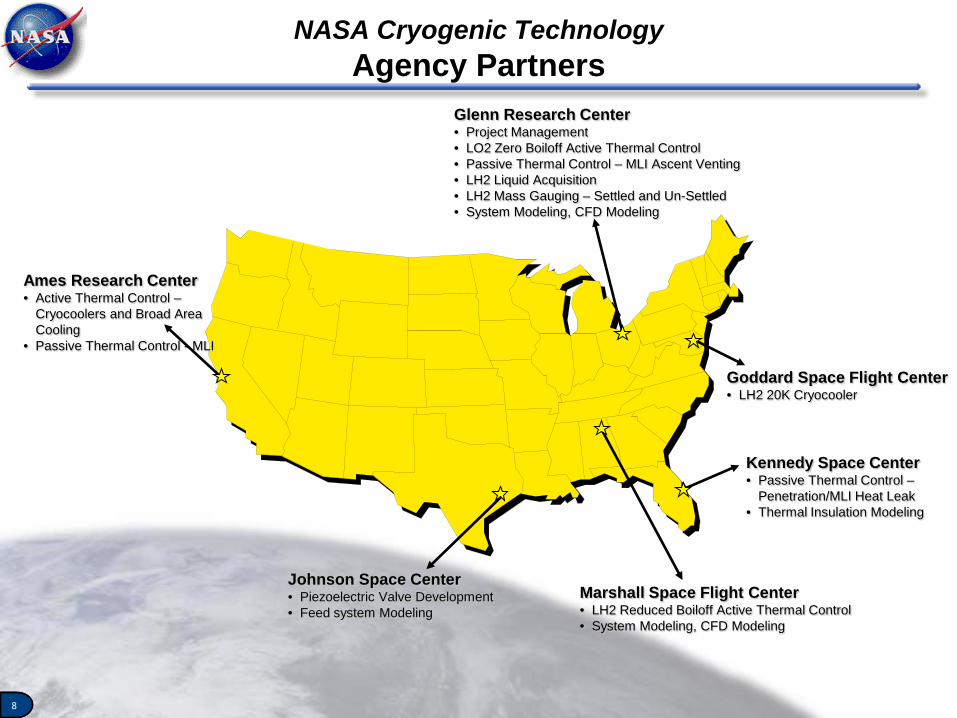
NASA Cryogenic TechnologyAgency Partners
Glenn Research Center• Project Management• LO2 Zero Boiloff Active Thermal Control• Passive Thermal Control – MLI Ascent Venting• LH2 Liquid Acquisition• LH2 Mass Gauging – Settled and Un-Settled• System Modeling, CFD Modeling
Ames Research Center• Active Thermal Control –
Cryocoolers and Broad Area Cooling
• Passive Thermal Control - MLI
Goddard Space Flight Center• LH2 20K Cryocooler
Johnson Space Center• Piezoelectric Valve Development• Feed system Modeling
Marshall Space Flight Center• LH2 Reduced Boiloff Active Thermal Control• System Modeling, CFD Modeling
Kennedy Space Center• Passive Thermal Control –
Penetration/MLI Heat Leak• Thermal Insulation Modeling
9
NASA Cryogenic TechnologyArchitectural Benefit (Drivers)
• Storage Technology– Long-term storage (temperature and pressure control) of cryogenic
propellants (LO2, LH2) in low-gravity and microgravity environments with minimal propellant losses.
– Improved storage of cryogens at launch site
• Distribution Technology– Maintain vapor-free liquid propellant between the tank outlet and the Main
Engine/RCS engine inlet.
• Low-g Propellant Management Technology– Provide vapor-free liquid propellant at the tank outlet.– Enable accurate and reliable measurements of cryogenic liquid mass in low-
gravity storage tanks with minimal propellant settling, minimizing undue constraints on mission, or spacecraft subsystems.
10
Baseline CFD Models Validated Against K-Site, MHTB, and S-IVB Data
PT: Cryogenic Fluid ManagementPM: Mary WadelPI: Jeffrey Moder
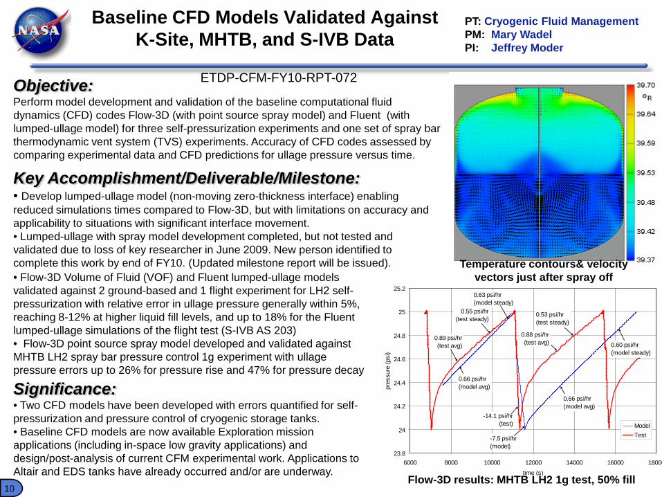
Objective:Perform model development and validation of the baseline computational fluid dynamics (CFD) codes Flow-3D (with point source spray model) and Fluent (with lumped-ullage model) for three self-pressurization experiments and one set of spray bar thermodynamic vent system (TVS) experiments. Accuracy of CFD codes assessed by comparing experimental data and CFD predictions for ullage pressure versus time.
Key Accomplishment/Deliverable/Milestone:• Develop lumped-ullage model (non-moving zero-thickness interface) enabling reduced simulations times compared to Flow-3D, but with limitations on accuracy and applicability to situations with significant interface movement.• Lumped-ullage with spray model development completed, but not tested and validated due to loss of key researcher in June 2009. New person identified to complete this work by end of FY10. (Updated milestone report will be issued).
Significance:• Two CFD models have been developed with errors quantified for self-pressurization and pressure control of cryogenic storage tanks.• Baseline CFD models are now available Exploration mission applications (including in-space low gravity applications) and design/post-analysis of current CFM experimental work. Applications to Altair and EDS tanks have already occurred and/or are underway.
23.8
24
24.2
24.4
24.6
24.8
25
25.2
6000 8000 10000 12000 14000 16000 18000
time (s)
pres
sure
(psi
)
ModelTest
0.63 psi/hr(model steady)
0.55 psi/hr(test steady)
0.60 psi/hr(model steady)
0.53 psi/hr(test steady)
-14.1 psi/hr(test)
-7.5 psi/hr(model)
0.89 psi/hr(test avg)
0.66 psi/hr(model avg)
0.88 psi/hr(test avg)
0.66 psi/hr(model avg)
• Flow-3D Volume of Fluid (VOF) and Fluent lumped-ullage models validated against 2 ground-based and 1 flight experiment for LH2 self-pressurization with relative error in ullage pressure generally within 5%, reaching 8-12% at higher liquid fill levels, and up to 18% for the Fluent lumped-ullage simulations of the flight test (S-IVB AS 203)• Flow-3D point source spray model developed and validated against MHTB LH2 spray bar pressure control 1g experiment with ullage pressure errors up to 26% for pressure rise and 47% for pressure decay
Temperature contours& velocity vectors just after spray off
Flow-3D results: MHTB LH2 1g test, 50% fill
ETDP-CFM-FY10-RPT-072
11
LH2 RF Mass Gauge Test Data ReviewPT: Cryogenic Fluid ManagementPM: Mary WadelPI: Dr. Greg Zimmerli
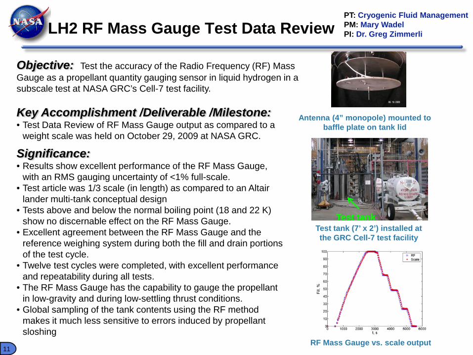
Objective: Test the accuracy of the Radio Frequency (RF) Mass Gauge as a propellant quantity gauging sensor in liquid hydrogen in a subscale test at NASA GRC’s Cell-7 test facility.
Key Accomplishment /Deliverable /Milestone:• Test Data Review of RF Mass Gauge output as compared to a
weight scale was held on October 29, 2009 at NASA GRC.
Significance:• Results show excellent performance of the RF Mass Gauge,
with an RMS gauging uncertainty of <1% full-scale.• Test article was 1/3 scale (in length) as compared to an Altair
lander multi-tank conceptual design• Tests above and below the normal boiling point (18 and 22 K)
show no discernable effect on the RF Mass Gauge.• Excellent agreement between the RF Mass Gauge and the
reference weighing system during both the fill and drain portions of the test cycle.
• Twelve test cycles were completed, with excellent performance and repeatability during all tests.
• The RF Mass Gauge has the capability to gauge the propellant in low-gravity and during low-settling thrust conditions.
• Global sampling of the tank contents using the RF method makes it much less sensitive to errors induced by propellant sloshing
Test tank (7’ x 2’) installed at the GRC Cell-7 test facility
RF Mass Gauge vs. scale output
Antenna (4” monopole) mounted to baffle plate on tank lid
Test tank
12
1/09/09 LH2 J-T clogging - 8,200 Lohm Visco Jet 35 psia inlet pressure, 36 - 40 deg R inlet temperature
0
20
40
60
80
100
120
140
160
22000 22200 22400 22600 22800 23000 23200 23400 23600 23800 24000
second
slpm
heater on heater off
Flow rate recovery to initial value
Partially blocked flow
LH2 Joule-Thomson Clogging Mitigation Tests PT: Cryogenic Fluid ManagementPM: Mary WadelPI: John Jurns
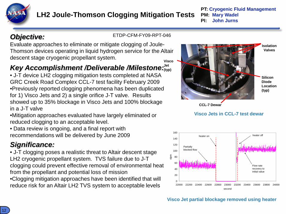
Objective:Evaluate approaches to eliminate or mitigate clogging of Joule-Thomson devices operating in liquid hydrogen service for the Altair descent stage cryogenic propellant system.
Key Accomplishment /Deliverable /Milestone:• J-T device LH2 clogging mitigation tests completed at NASA GRC Creek Road Complex CCL-7 test facility February 2009•Previously reported clogging phenomena has been duplicated for 1) Visco Jets and 2) a single orifice J-T valve. Results showed up to 35% blockage in Visco Jets and 100% blockage in a J-T valve•Mitigation approaches evaluated have largely eliminated or reduced clogging to an acceptable level. • Data review is ongoing, and a final report with recommendations will be delivered by June 2009
Significance:• J-T clogging poses a realistic threat to Altair descent stage LH2 cryogenic propellant system. TVS failure due to J-T clogging could prevent effective removal of environmental heat from the propellant and potential loss of mission•Clogging mitigation approaches have been identified that will reduce risk for an Altair LH2 TVS system to acceptable levels
Visco Jet partial blockage removed using heater
Silicon Diode Location (typ)
CCL-7 Dewar
Visco Jet (typ)
IsolationValves
Visco Jets in CCL-7 test dewar
ETDP-CFM-FY09-RPT-046
13
Methane Lunar Surface Thermal Control Test Data Review
PT: Cryogenic Fluid ManagementPM: Mary WadelPI: David Plachta
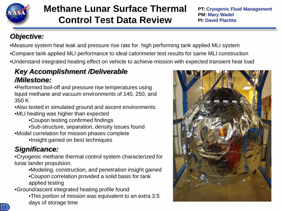
Objective:•Measure system heat leak and pressure rise rate for high performing tank applied MLI system•Compare tank applied MLI performance to ideal calorimeter test results for same MLI construction •Understand integrated heating effect on vehicle to achieve mission with expected transient heat load
Key Accomplishment /Deliverable /Milestone:•Performed boil-off and pressure rise temperatures using liquid methane and vacuum environments of 140, 250, and 350 K•Also tested in simulated ground and ascent environments•MLI heating was higher than expected
•Coupon testing confirmed findings•Sub-structure, separation, density issues found
•Model correlation for mission phases complete•Insight gained on best techniques
Significance:•Cryogenic methane thermal control system characterized for lunar lander propulsion.
•Modeling, construction, and penetration insight gained•Coupon correlation provided a solid basis for tank applied testing
•Ground/ascent integrated heating profile found•This portion of mission was equivalent to an extra 3.5 days of storage time
14
Hi Flow LADs Test Data Review PT: CFMPM: Mary WadelPI: David Chato
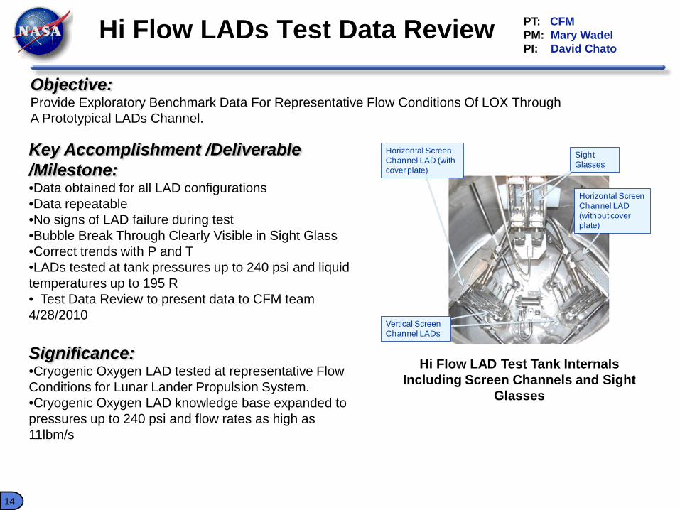
Objective:Provide Exploratory Benchmark Data For Representative Flow Conditions Of LOX Through A Prototypical LADs Channel.
Key Accomplishment /Deliverable /Milestone:•Data obtained for all LAD configurations•Data repeatable•No signs of LAD failure during test•Bubble Break Through Clearly Visible in Sight Glass •Correct trends with P and T•LADs tested at tank pressures up to 240 psi and liquid temperatures up to 195 R• Test Data Review to present data to CFM team 4/28/2010
Significance:•Cryogenic Oxygen LAD tested at representative Flow Conditions for Lunar Lander Propulsion System.•Cryogenic Oxygen LAD knowledge base expanded to pressures up to 240 psi and flow rates as high as 11lbm/s
Horizontal Screen Channel LAD (with cover plate)
Horizontal Screen Channel LAD (without cover plate)
Sight Glasses
Vertical Screen Channel LADs
Hi Flow LAD Test Tank Internals Including Screen Channels and Sight
Glasses
15
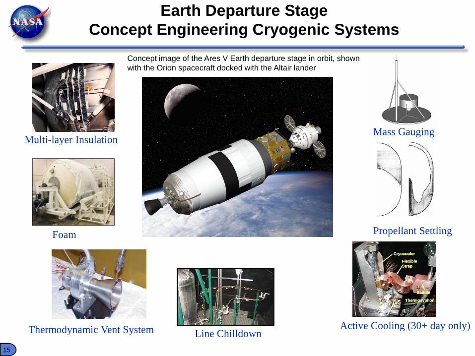
Earth Departure StageConcept Engineering Cryogenic Systems
Multi-layer Insulation
Foam
Thermodynamic Vent System
Concept image of the Ares V Earth departure stage in orbit, shown with the Orion spacecraft docked with the Altair lander
Liquid Hydrogen
Liquid Oxygen
Line ChilldownActive Cooling (30+ day only)
Propellant Settling
Cryocooler
Saddle
Flexible Strap
Thermosyphon
Cryocooler
Saddle
Flexible Strap
Thermosyphon
Cryocooler
Saddle
Flexible Strap
Thermosyphon
Mass Gauging
16
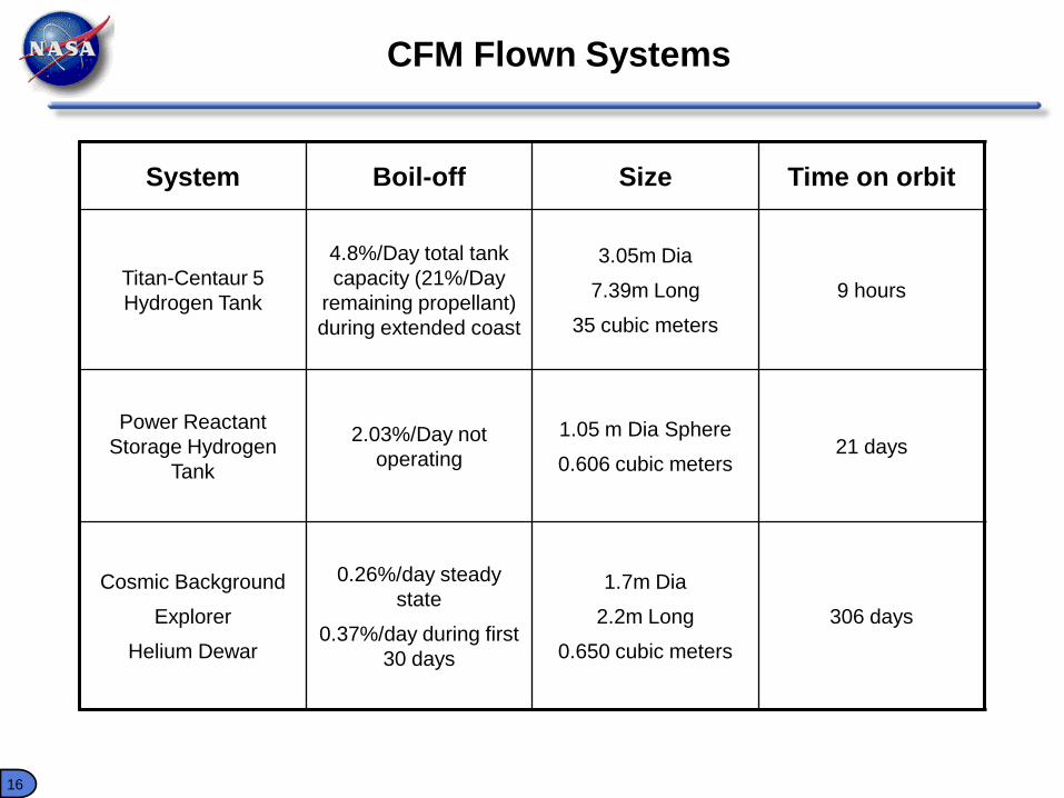
CFM Flown Systems
System Boil-off Size Time on orbit
Titan-Centaur 5 Hydrogen Tank
4.8%/Day total tank capacity (21%/Day
remaining propellant) during extended coast
3.05m Dia
7.39m Long
35 cubic meters
9 hours
Power Reactant Storage Hydrogen
Tank
2.03%/Day not operating
1.05 m Dia Sphere
0.606 cubic meters21 days
Cosmic Background
Explorer
Helium Dewar
0.26%/day steady state
0.37%/day during first 30 days
1.7m Dia
2.2m Long
0.650 cubic meters
306 days
17
NASA and DOE Cryogenic Storage
Similarities:• Require Long term storage of Hydrogen with low loss• Use hydrogen for propulsion and power applications• Rely on evacuated MLI for thermal protection ( at least for liquid storage)• Rely on low heat leak composites to reduce thermal load• Governed by same laws of Heat Transfer and Thermodynamics• NASA PRSD supercritical system similar (although lower pressure) to DOE
Cryo-Compressed Hydrogen StorageDifferences:• NASA can often use vacuum of space for both MLI and safe venting of
Hydrogen• NASA’s Larger Systems gain surface area to volume advantage over DOE
automotive systems• DOE automotive volume biggest constraint; NASA mass biggest constraint
18
• NASA is focusing on the development of cryogenic storage systems, low-gravity propellant management systems, cryogenic transfer and handling technologies needed to provide necessary data and relevant experience to support informed decisions on implementation of cryogenic systems into advanced NASA missions.
• NASA Requires Long Term Cryogenic storage for the Success of Future Missions
• Continued Exchange of Ideas Between NASA and DOE Will Aid Both Agency’s Efforts
Closing Remarks