compression and affine transforms resilient...
TRANSCRIPT

COMPRESSION AND AFFINE TRANSFORMS RESILIENT
WATERMARKING
Fahri Asvaroğlu
Submitted to the Institute of Graduate Studies and Research
in partial fulfillment of the requirements for the Degree of
Master of Science in
Electrical and Electronic Engineering
Eastern Mediterranean University February 2006, Gazimağusa

ii
Approval of the Institute of Graduate studies and Research ____________________________________ Prof. Dr. Ufuk Taneri Director I certify that this thesis satisfies the requirements as a thesis for the degree of Master of Science in Electrical and Electronic Engineering. _____________________________________ Prof. Dr. Derviş Z. Deniz
Chair, Department of Electrical and Electronic Engineering
We certify that we have read this thesis and that in our opinion it is fully adequate in scope and quality as a thesis for the degree of Master of Science in Electrical and Electronic Engineering. _______________________________________ Asst. Prof. Dr. Erhan A. İnce Supervisor Examining Committee 1. Asst. Prof. Dr. Erhan A. İnce ______________________________
2. Assoc. Prof. Dr. Hüseyin Özkaramanlı ______________________________
3. Asst. Prof. Dr. Hasan Demirel ______________________________
iii
ABSTRACT
Compression and General Affine Transformations Resilient Watermarking
Copy protection and intellectual rights management are pressing concerns of the
content owners who distribute content in the new digital world. Digital watermarking
technology is perceived as an enabling agent that allows more widespread sharing
and utilization of content while lessening the piracy worries. Many of the techniques
for embedding marks in digital images have been inspired by methods of image
coding and compression. Some of these include using the Discrete Cosine Transform
(DCT), Wavelets, Linear Predictive Coding, and Fractals. It has been demonstrated
that these methods perform well against compression however they lack robustness
to geometric transformations (attacks). Consequently, methods have emerged which
exploit the properties of the discrete Fourier transform (DFT) to achieve robustness
against rotation and scaling. The DFT methods can be divided into two categories.
Those based on invariance and those that embeds a template into the image which is
searched for during the detection of the watermark and yields the transformation
undergone by the image. Both of these methods exploit the properties of log-polar-
maps (LPM) and can only be used to detect changes of rotation and scale. Similarly
the log-log-map (LLM), allows the detection of aspect ratio changes however is still
unable to recover general transformations. In this work we combine two state of the
art techniques to develop a hybrid watermarking technique, which is both
compression and general affine transformation resilient. The watermark bits are
embedded in the DC components since the DC components have much larger

iv
perceptual capacity than any AC component. An adaptive watermarking algorithm
making use of the feature of texture masking of HVS is adopted. For recovering a
watermark from an image, which has undergone a general affine transformation, the
method proposed by Pereira is adopted. Unlike algorithms, which use log-polar or
log-log-maps, Pereira’s method concentrates on searching the space of possible
transformations. Since an exhaustive search is not possible careful pruning of the
search space is necessary. Simulation results indicate that the hybrid method would
be more advantageous in comparison to any stand-alone technique. Besides being
resilient against scaling and rotation the hybrid method is also resilient to general
affine transformations such as shearing, aspect ratio changes.
Keywords: DC coefficient watermarking, general affine transform matrix, Peak
signal to noise ratio, Template matching.

v
ÖZET
Sıkıştırma ve Genel İlgin Dönüşümlere Dirençli
Damgalama Yeni sayısal dünyamızda içeriği dağıtan mal sahiplerinin en büyük endişelerinden
ikisi kopyalamaya karşı koruma ve enetellektüel hak ve yetkilerinin korunması
konusudur. Sayısal damgalama teknolojisi bilginin daha geniş paylaşımına ve
kullanımına imkan kılarken ayni zamanda da korsanlıkla ilgili kaygıları azaltan bir
unsur olarak görülmektedir. Sayısal imgeler içine gizli damga yerleştirme
yöntemlerinden birçoğu imge kodlama ve sıkıştırma yöntemlerinden
esinlenmektedir. Bunların bazıları ayrık kosinüs dönüşümü (AKD), Dalgacıklar,
Doğrusal öngörücü kodlama, ve Fraktalları kullanmaktadır. Bu yöntemlerin
sıkıştırmaya karşı dayanıklı fakat genel geometrik dönüşümlere karşı zayıf oldukları
bilinmektedir. Bu nedenle dönme ve ölçeklemeye karşı dayanıklı olacak ayrık
Fourier dönüşümü (AFD) özelliklerini kullanan yeni metotlar üretilmiştir. AFD
yöntemleri iki sınıfta toplanabilir. Sabit nicelik özelliğine bağlı olanlar ve imge içine
bir şablon yerleştirenler. Bu yöntemlerden her ikisi de log-kutupsal-eşleme
özelliklerini kullanmakta ve sadece dönme ve ölçeklemede olan değişiklikleri
kestirebilmektedirler. Bunlara benzer olarak Deguillaume tarafından sunulan ve log-
log-eşleme özelliklerini kullanan yöntem her ne kadar da en-boy-oranı
değişikliklerini kestirmede işe yarasa da genel ilgin dönüşümlerini hala daha doğru
kestirememektedir. Bu çalışma en son teknoloji iki yöntemi birleştirerek hem
sıkıştırma hem de ilgin dönüşümlere dayanıklı karma bir yöntem geliştirmiştir.
Damga ikili sayıları ayrık kosinüs dönüşümünün DC bileşenlerine yerleştirilmiştir.

vi
DC bileşenlerinin AC bileşenlerine kıyasla çok daha fazla algısal kapasitesi olduğu
belgelenmiştir. İkili sayıları DC bileşenlerine yerleştirmek için doku özniteliğini
kullanan uyarlanır bir damgalama tekniği kullanılmıştır. Genel ilgin dönüşüme
uğramış bir imgeden gizli damgayı çıkarmak için Pereira tarafından teklif edilen
yöntem benimsenmiştir. Log- kutupsal-eşleme ve log-log-eşleme özelliğini kullanan
yöntemlerin tersine, Pereira olası ilgin dönüşümler uzayını taramayı tercih etmiştir.
Bu uzayın tümünü kaba kuvvetle taramak mümkün olmadığından dikkatli budama
bir gereksinim olmuştur. Benzetim sonuçları karma metodun kendi başına
kullanılacak diğer yöntemlere kıyasla daha avantajlı olacağını göstermiştir. Yeni
karma yöntemin ölçekleme ve dönme yanında genel ilgin dönüşümlerden olan
makaslama ve en-boy-oranı değişikliklerine karşı da dayanıklı olduğu
gözlemlenmiştir.
Anahtar sözcükler: DC katsayısı damgalma, Genel ilgin dönüşüm matrisi, Doruk
sinyal gürültü oranı, Şablon eşleştirme

vii
DEDICATION
To My Parents

viii
ACKNOWLEDGEMENTS
I would like to give my sincere gratitude to my supervisor Asst. Prof. Dr. Erhan A.
İnce for his continuous support and wholehearted collaboration in this subject.
My personal thanks to Assoc. Prof. Dr. Hüseyin Özkaramanlı, Asst. Prof. Dr. Hasan
Demirel for giving their time in the contribution of the thesis as Jury members.
Many thanks to my department and fellow associates for their help and support
during my course of study. Great thanks to all of my friends for their presence, as it
enhanced my motivation by making me feel at home.

ix
LIST OF FIGURES
Fig 1.1: Category I Watermarking Scheme............................................................. 4 Fig 1.2: Category II Watermarking Scheme ........................................................... 5 Fig 1.3: Category III Watermarking Scheme.......................................................... 8 Fig 2.1: Middle band frequencies in a DCT block ................................................ 13 Fig 2.2: Effect of watermarking in the DCT domain............................................ 15 Fig 2.3: Block Mapping Process.............................................................................. 16 Fig 2.4: The embedding positions of the low frequency ....................................... 17 Fig 2.5: Adaptive Watermarking System .............................................................. 18 Fig 2.6: Four level decomposed image ................................................................... 19 Fig 3.1: Clockwise Transformation by θ degrees.................................................. 23 Fig 3.2: Rotation, scale and translation invariant watermarking ....................... 25 Fig 3.3: 2D Bartlett window .................................................................................... 28 Fig 4.1: Block Diagram of the Hybrid Watermarking System Proposed ........... 33 Fig 4.2: Texture classified blocks............................................................................ 35 Fig 4.3: Original LENA image and log of magnitude of DFT ............................. 38 Fig 4.4: Detected Local Peaks ................................................................................. 41 Fig 5.1: Grayscale Standard Test Images .............................................................. 43 Fig 5.2: RGB Standard Test Images ...................................................................... 44 Fig 5.3: DCT domain watermarking using mid-band frequency components... 45 Fig 5.4: Robustness against JPEG compression using mid-band DCT
watermarking ............................................................................................ 46 Fig 5.5: DC-Component Based DCT Domain Watermarked Images ................. 47 Fig 5.6: The original and extracted watermarks from stego grayscale images.. 48 Fig 5.7: PSNR for DC-component based watermarked color images................. 49 Fig 5.8: Watermarks extracted from stego color images ..................................... 49 Fig 5.9: Robustness of DC-coefficient watermarking against JPEG compression
..................................................................................................................... 50 Fig 5.10: Watermarking using multiple copies of the authentication data ........ 51 Fig 5.11: Re-assembling the authentication data from extracted parts .............. 51 Fig 5.12: All-round Cropping ................................................................................. 52 Fig 5.13: Diagonal Cropping................................................................................... 52 Fig 5.14: 65° rotation attack.................................................................................... 54 Fig 5.15: 25° rotation attack.................................................................................... 55 Fig 5.16: Scaling with fixed aspect ratio ................................................................ 56 Fig 5.17: Scaling with X=0.7 and Y=0.6................................................................. 57 Fig 5.18: Proposed Hybrid Watermarking applied with a 35 degree attack...... 60 Fig 5.19: Proposed Hybrid Watermarking applied with a -15 degree attack .... 61 Fig 5.20: Recovery from Scaling Attacks............................................................... 62

x
LIST OF TABLES
Table 5.1: PSNR values for extracted watermarks from JPEG......................... 46 Table 5.2: PSNR values for watermarks extracted from grayscale images ...... 48 Table 5.3: PSNR values for watermarks extracted from color images.............. 50 Table 5.4: Restored size and MSE values after scaling attack............................ 56 Table 5.5: Restored size and MSE values after aspect ratio attack. .................. 57 Table 5.6: Effect of rounding errors on the absolute difference value .............. 59

xi
TABLE OF CONTENTS
ABSTRACT............................................................................................................... iii
ÖZET .......................................................................................................................... v
DEDICATION.......................................................................................................... vii
ACKNOWLEDGEMENTS.................................................................................... viii
LIST OF FIGURES .................................................................................................. ix
LIST OF TABLES ..................................................................................................... x
LIST OF SYMBOLS .............................................................................................. xiii
LIST OF ABBREVIATIONS ................................................................................ xiv
1 INTRODUCTION................................................................................................... 1 1.1 Category I Watermarks ...................................................................................... 3
1.2 Category II Watermarks..................................................................................... 4
1.2.1 Spatial Domain Category II Watermarking................................................ 5 1.2.2 Frequency Domain Category II Watermarking .......................................... 6
1.3 Category III Watermarking Schemes................................................................. 7
1.4 Literature Survey ............................................................................................... 8
1.5 Thesis Outline .................................................................................................. 11
2 DISCRETE COSINE & DISCRETE WAVELET TRANSFORM BASED WATERMARKING TECHNIQUES.................................................................. 12 2.1 DCT Based Watermarking Approaches........................................................... 12
2.1.1 Middle-Band Coefficient Usage................................................................ 13 2.1.2 Low Frequency Coefficient Usage and Weighted correction ................... 15
2.2 Discrete Wavelet Transform Based Watermarking ......................................... 18
3 METHODS FOR ESTIMATING AND RECOVERING FROM GENERAL AFFINE TRANSFORMS..................................................................................... 21 3.1 Affine Transformations.................................................................................... 21
3.1.1 Constant scaling factor in both dimensions .............................................. 22 3.1.2 Changing the aspect ratio of an image by unequal scale factors ............. 22

xii
3.1.3 Clockwise and anti-clockwise rotations.................................................... 23 3.1.4 Shearing .................................................................................................... 24
3.2 Log-Polar Mapping.......................................................................................... 24
3.3 Log-Log Mapping............................................................................................ 25
3.4 RST Invariant Phase Only Filtering Method ................................................... 26
3.5 Template Embedding in the Fourier Domain .................................................. 26
3.5.1 Embedding the Synchronization Template................................................ 27 3.5.2 Template Detection ................................................................................... 28
4 ROBUST HYBRID METHOD RESISTANT TO COMPRESSION AND GENERAL AFFINE TRANSFORMS................................................................ 31
4.1 DC Components Based DCT Domain Watermarking ..................................... 33
4.2 Template Addition in DFT Domain................................................................. 36
5 SIMULATION RESULTS ................................................................................... 42 5.1 Standard Test Images....................................................................................... 42
5.2 Discrete Cosine Transform Domain Watermarking ........................................ 44
5.3 DCT domain DC-Component Based Watermarking ....................................... 47
5.3.1 DCT domain DC-Component Based Watermarking of color images....... 48 5.3.2 Robustness Test against JPEG compression ............................................ 50 5.3.3 Cropping Resilience Test .......................................................................... 51
5.4 Template based DFT domain watermarking technique ................................... 52
5.4.1 Detecting angle of Rotation ...................................................................... 53 5.4.2 Constant Scaling in both directions .......................................................... 55 5.4.3 Aspect Ratio Change ................................................................................. 57
6 CONCLUSIONS & FUTURE WORK ............................................................... 63

xiii
LIST OF SYMBOLS
A Linear transformation matrix
Bk kth block of cover image
e(x,y) Binary edge map
f(x,y) Cover image
I Cover image
IW Watermarked image
tr
Translation matrix
W Watermark data
X Original watermark
X* Recovered watermark
α Template embedding strength
θ Rotation angle
ρ Similarity Factor
xiv
LIST OF ABBREVIATIONS
DCT Discrete Cosine Transform
DFT Discrete Fourier Transform
LSB Least Significant Bit
HVS Human Visual System
WT Wavelet Transform
JPEG Joint Photographic Experts Group
EZW Embedded Zero tree Wavelet
FMW Fourier-Mellin Watermarking
TMW Template Matching-based Watermarking
LPM Log-Polar Mapping
DWT Discrete Wavelet Transform
PN Pseudo Random Number
SPIHT Set Partitioning in Hierarchical Trees
QMF Quadrature Mirror Filter
LLM Log-Log Mapping
PSNR Peak Signal-to-Noise Ratio
RGB Red-Green-Blue
MSE Mean Squared Error
DivX Digital Video Express
ISBN International Standard Book Number

1
CHAPTER 1
1 INTRODUCTION
In the past decade there has been an explosion in the use and distribution of digital
multimedia data. Personal computers (PCs) with Internet connections have literally
taken homes by storm and have made the distribution of both legal and illegal data
and applications much easier and faster. Although digital data has several advantages
over its analog counterparts, service providers are reluctant to offer services online
because they fear the unrestricted duplication and dissemination of copyrighted
material.
Since ancient times, there existed ways of establishing the identity of the owner of an
object in case of dispute. These early methods range from simply inscribing the name
of the owner on the object to embedding the owners seal in the object (like a tattoo
on the head of a slave). In the modern era, literary works have been copyrighted,
goods embedded with company logos, and ideas patented to ensure that the owner of
a piece of work is always given his due. Books contain ISBN numbers to uniquely
identify the work and establish ownership.
Companies have come up with means of identifying their work such as encrypted
information hidden in the code, newer formats such as DivX which also contain
author information as part of the header. These identifying data snippets are referred
to as digital watermarks. As with the more conventional idea of a watermark being
part of a currency note to ensure authenticity of the note, digital watermarks can be
used to identify the works as belonging to a company or individual. Watermarks
encrypt the information as an imperceptible signal, which is added to the data in such
a way that it is retainable.

2
Information hiding has been undertaken in three subgroups: steganography, tamper-
proofing, and watermarking. In the case of steganography we are interested in
sending large quantities of information however we are less concerned with
robustness. Tamper proofing [1], involves embedding information into the cover
object which is then used at detection to determine if and how the object has been
modified. One major application is in the authentication of digital evidence in a court
case. Watermarking is a special case of the general information hiding problem. The
idea is to robustly embed the owner’s information into a medium known as the cover
object in order to produce what is referred to as the stego object. The embedding
process should be chosen such that the cover data and the stego should be
indistinguishable. Cover objects may include images, video, music and text
documents. Robustness is of prime importance since a hacker may intentionally
attempt to remove the watermark. Furthermore we require that the watermark be
invisible since the cover object is of value. The capacity requirement is also much
lower in comparison to steganography since we only have a small amount of
identifying information to communicate. This is roughly around 80-100 bits.
To embed watermark information in a host data, watermark embedding techniques
apply minor modifications to the host data in a perceptually invisible manner, where
the modifications are related to the watermark information. The watermark
information can later be retrieved from the watermarked data by detecting the
presence of these modifications. A wide range of modifications in any domain can be
used as watermarking techniques. Prior to embedding or extracting a watermark, the
host data can be converted to the spatial domain, the Fourier, the wavelet, the
discrete cosine transform, or even fractal domain where the properties of the specific
transform domains can be exploited. In these domains least significant bit (LSB)
modifications, noise addition, coefficient re-ordering, coefficient removal, warping
and morphing of data parts can be exploited. Furthermore the impact of the
modifications can be minimized with the aid of human visual models.

3
In [2] Cox has described three watermarking categories which can be used to classify
all algorithms. Within his framework the algorithms are categorized relative to the
type of embedding strategy adopted (linear or otherwise). The various algorithms in
the literature more or less follow these three categories starting from the oldest
Category-I and covering up to the recent Category-III algorithms.
1.1 Category I Watermarks The block diagram of the Category I scheme is depicted in figure 1.1. The
watermarking process consists of generating an encoded watermark, setting a global
strength and then adding the result to the image which produces the stego image. It is
worth noting that the strength is set globally and independently of the image. Several
early methods classify under this framework. In [3] Tirkel proposed adding an M-
sequence to the least significant bit of each pixel of the image. M-sequences which
are bipolar have excellent autocorrelation properties which can be exploited at the
time of decoding. Another idea that appeared in several variants was the Patchwork
algorithm developed by Bender in [4]. Benders’s algorithm consist of selecting
random pairs of pixels (ai , bi) and increasing the ai’s by one and decreasing the bi’s
by one. The watermark is detected by comparing, the sum of differences between,
ai’s and bi’s, to a threshold which is chosen so that the probability of false detection
is below a certain level.

4
Fig 1.1: Category I Watermarking Scheme
The initial watermarking algorithm developed by DIGIMARK is also an example of
category I algorithm.
1.2 Category II Watermarks
In this category the main improvement lies in the fact that the image is now used for
generation of a perceptual mask. The watermark is then generated in accordance with
this mask so as to embed most strongly in regions where the watermark will be
invisible and less strongly where the watermark will be easily seen. The block
diagram of the category II scheme is as shown in figure 1.2.
Encoded Watermark
Attenuator
Image to be Watermarked
Watermarked Image

5
Fig 1.2: Category II Watermarking Scheme
1.2.1 Spatial Domain Category II Watermarking One of the very first schemes that was developed to operate in spatial domain and
that falls into this category is that of Goffin [5]. The watermark consists of a spatial
domain binary pattern which is low-pass filtered, frequency modulated, masked and
then added to the host data. Alternatively the watermark decoding is done by
demodulating and then comparing the correlation values with a threshold. A second
approach had been proposed by Kutter in [6] suggesting the usage of luminance
masking in the blue channel. It has been demonstrated that the Human Visual System
(HVS) is less sensitive to the blue channel when compared to the red and green
components. Kutters approach will embed a binary number through amplitude
modulation in the spatial domain. A bit is embedded at a pseudo-randomly selected
location ( )ji, by either adding or subtracting a value proportional to the luminance at
the same location (based on the bit). To recover an embedded bit, an estimate of the
original, non-watermarked value is computed using a linear combination of
Encoded Watermark
Perceptual Model
Attenuator
WatermarkedImage
Image to be watermarked
Local PowerConstraints
6
neighboring pixels in a cross shape. The bit value may be determined by looking at
the sign of the difference between the pixel under inspection and the estimated
original.
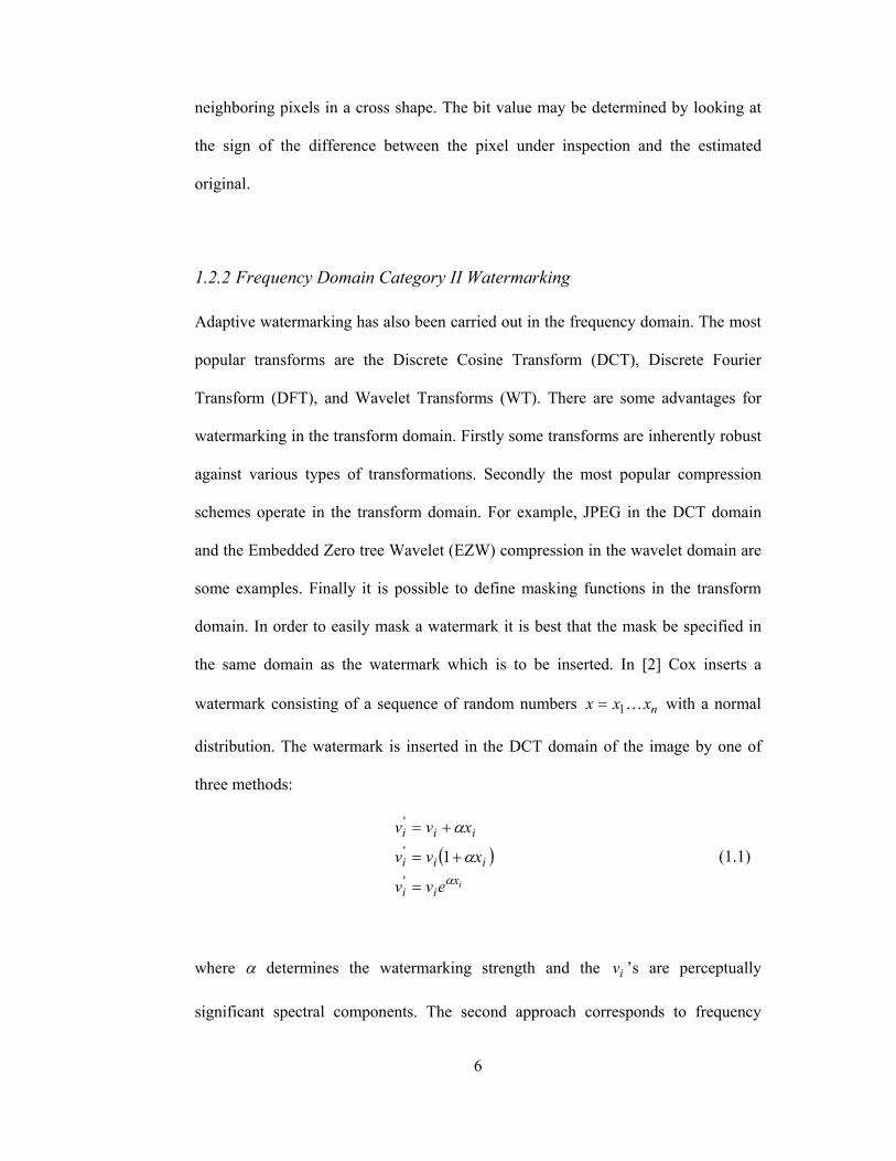
1.2.2 Frequency Domain Category II Watermarking
Adaptive watermarking has also been carried out in the frequency domain. The most
popular transforms are the Discrete Cosine Transform (DCT), Discrete Fourier
Transform (DFT), and Wavelet Transforms (WT). There are some advantages for
watermarking in the transform domain. Firstly some transforms are inherently robust
against various types of transformations. Secondly the most popular compression
schemes operate in the transform domain. For example, JPEG in the DCT domain
and the Embedded Zero tree Wavelet (EZW) compression in the wavelet domain are
some examples. Finally it is possible to define masking functions in the transform
domain. In order to easily mask a watermark it is best that the mask be specified in
the same domain as the watermark which is to be inserted. In [2] Cox inserts a
watermark consisting of a sequence of random numbers nxxx K1= with a normal
distribution. The watermark is inserted in the DCT domain of the image by one of
three methods:
( )ix
ii
iii
iii
evv
xvv
xvv
α
α
α
=
+=
+=
'
'
'
1 (1.1)
where α determines the watermarking strength and the iv ’s are perceptually
significant spectral components. The second approach corresponds to frequency

7
masking. In this approach the strong coefficients are changed more than the weak
ones. In the verification of the watermark, normalized correlation coefficient is used:
( )∗∗
∗∗ =
XX
XXXXsim , (1.2)
where ∗X is the recovered watermark obtained by taking the difference between the
recovered image and the original image and X is the original watermark.
1.3 Category III Watermarking Schemes
In this method the improvement over category II watermarking is the fact that all
information about the image is now used to generate a watermark of maximal
robustness. This category is relatively new and hence little work has been done for it.
One method proposed by Cox treats both the image and watermark as vectors.
During the embedding the knowledge of the image vector 0r is used to compute a
region S( 0r ) within which visibility constraints on the image are satisfied [7]. The
watermarking approach consists of choosing a vector from within this region so that
for a fixed detection strategy, the probability of detection is maximized. A block
diagram of the category III scheme is as depicted in figure 1.3.

8
Fig 1.3: Category III Watermarking Scheme
1.4 Literature Survey
A great deal of research has been focused on digital image watermarking during the
past decade. The techniques proposed are either in the spatial or the transform
domain. The simplest example of watermarking is to embed a watermark in the least
significant bits (LSBs) of the image pixels [8]. Cox et al. [2] used the spread
spectrum communication for digital multimedia watermarking. A Gaussian
distributed sequence is embedded into the perceptually most significant frequency
components of the cover data. Hsu and Wu [9] embedded an image watermark in the
selectively modified middle frequency band of the discrete cosine transform
coefficients of the cover data. In [4], Bender describes a statistical method referred to
as the Patchwork algorithm. The method randomly chooses n pairs of image
points ( )ii ba , , and increases the brightness at ai by one unit while correspondingly
decreasing the brightness of bi. The expected value of the sum of the differences of
Encoded Watermark Fidelity and
Detection Enhancer
WatermarkedImage
Image to be Watermarked

9
the n pairs of points is then 2n, provided certain statistical properties of the image are
true.
In [10], Nikolaidis and Pitas proposed a method for copyright protection where an
invisible signal known as the digital signature is embedded into the image. Signature
casting was performed in the spatial domain by slightly modifying the intensity level
of randomly selected image pixels. The signature was designed in such a way that it
was resistant to JPEG compression and lowpass filtering. The detector compared the
mean intensity value of the marked pixels against that of the unmarked pixels.
In most cases the research has been focused on grayscale image watermarking.
Extensions to the color case has been described in [11] and [12] by processing each
color channel separately. Alternative approaches for color image watermarking has
been advanced by Fleet and Heeger [13], who suggest to embed the watermark into
the yellow-blue channel of the opponent-color representation of color images. This
was followed by Kutter, Jordan, and Bossen in [6] where they suggested to embed
the watermark in the blue channel since the human eye is less sensitive to changes in
this band. However they ignored the correlation between color channels for both the
embedding and the decoding phases.
In 1999, Piva and Barni [14] suggested a new DCT domain technique which was
designed to exploit the characteristics of the human visual system (HVS) and the
correlation between the RGB channels.

10
In [18], Huang proposed an alternative approach for DCT domain watermarking.
Instead of embedding in the mid frequency band he suggested that the watermark is
embedded in the DC components of the (8×8) blocks. Huang claimed that the DC
components have much larger perceptual capacity than any AC component and
tempering with the watermarked image would be much harder since altering low
frequency coefficients will distort the cover data. An adaptive watermarking
algorithm making use of the feature of texture masking of HVS is adopted. The
proposed method is also more resistant to JPEG compression than the mid-band DCT
approach.
Even though most of the common frequency-based watermarking techniques are
robust to attacks such as JPEG compression, filtering, and noise addition they lack
robustness to geometrical transformations. To solve this problem two classes of
methods have been proposed to exploit the invariant properties of the DFT. These are
the Fourier-Mellin transform-based watermarking (FMW) and Template Matching-
based watermarking (TMW). FMW methods [23] are theoretically robust to
geometrical attacks due to the translation property of the 2D DFT. The scale-
invariance property is based on the cyclic shift after applying Log-Polar Maps (LPM)
on the 2D DFT, and rotation-invariance property is based on the cyclic shift after
applying another DFT on the LPM. However generating LPM requires interpolation
of neighboring magnitudes with a large dynamic range. The TMW methods [24, 25,
26] embed the template at certain 2D DFT magnitudes as the local peaks for
correcting geometrical distortions.

11
For the estimation of the affine transforms, some algorithms use constrained
exhaustive search aiming at the best fitting of the reference pattern with the analyzed
one [25],[26].
1.5 Thesis Outline
The thesis is organized as follows:
Chapter 1 provides a general introduction to the topic of watermarking, gives a
survey on the various different techniques used for watermarking, and outlines the
way the thesis is organized. Chapter 2 talks about watermarking in the spectrum
domain. It specifically introduces DCT based watermarking both in mid-band
frequencies and in the DC components. Chapter 3 discusses the methods for
estimating and recovering from general affine transforms. This section of the thesis
first introduces the different types of transformations that an attacker can apply to a
watermarked image. Secondly it discusses the different techniques proposed in the
literature that can be used for affine transform parameter estimation and outlines
some of their shortcomings. Chapter 4 introduces the robust hybrid method
proposed. Chapter 5 provides simulation results using a set of standard test images
and finally Chapter 6 provides conclusions and directions for future work.
To the best of our knowledge, there is no example in the literature combining the two
state of the art techniques described in order to achieve a highly robust watermarking
scheme that is not only affine transform resilient but also very much compression
invariant. There for we believe that the work is unique for providing preliminary
results on the new hybrid watermarking scheme proposed.

12
CHAPTER 2
2 DISCRETE COSINE & DISCRETE WAVELET TRANSFORM
BASED WATERMARKING TECHNIQUES
Watermarking techniques in the Discrete Cosine Transform (DCT) domain allow an
image to break up into different frequency bands, making it much easier to embed
the watermark information into the appropriate frequency bands of an image. The
low frequency band carries the most important visual parts of the image and the high
frequency band is exposed to removal through compression and noise attacks. The
middle frequency band helps avoid the removal and also don’t contain visual
information that is highly significant.
On the other hand the Discrete Wavelet Transform (DWT) separates an image to a
lower resolution approximation image (LL) as well as horizontal (HL), vertical(LH)
and diagonal (HH) detail components. One advantage of the DWT is the fact that it
models the HVS more accurately when compared to FFT or DCT. This way it is
possible to use higher energy watermarks in regions that the HVS is known to be less
sensitive.
2.1 DCT Based Watermarking Approaches Discrete cosine transform is one of many sinusoidal transforms basically obtained
from the real part (it carries the cosine terms) of the discrete Fourier transform. It
transforms the time domain or space domain of real input data into its elementary

13
frequency components. DCT of the image is calculated by taking (8×8) blocks of the
image, which are then transformed individually using 2D-DCT (type-II). DCT
approach is able to withstand some attacks such as low-pass filtering, high-pass
filtering and compression.
2.1.1 Middle-Band Coefficient Usage
It is a well known fact that when the transform of a block is taken the energy of the
block will be concentrated around the low frequencies. However it is also true that
embedding a watermark in the low frequency band makes the watermark perceptible.
In [9], Hsu and Wu stated that in order to avoid watermark removal due to
compression attacks and also to retain invisibility the watermark should be
embedded in the mid-band frequencies. A block DCT-based approach is adopted and
mid-band frequencies for each block are used in order to embed the entire payload.
Figure 2.1 below shows the location of the mid-band frequencies for one block of a
multi-block image.
Fig 2.1: Middle band frequencies in a DCT block

14
To embed a PN sequence or an image watermark (W) into the middle frequencies of
the DCT block, the transformed coefficient block ( )vuI , are modulated according to
eq. (2.1) below:
( )( ) ( )
( ) Mid
Mid
yx
yxyxW Fvu
FvuvuI
vuWkvuIvuI
yx ∉∈
⋅+
=,,
,,,
,,
,,,
(2.1)
Fmid denotes the middle band frequencies, k is the gain factor, ( )yx, the spatial
location of an (8×8) pixel block in image, and (u,v) the DCT coefficients in the
corresponding DCT block. Here we note that the watermark only affects the middle
band frequencies while leaving lower and higher frequency components relatively
unaffected. It is also possible to make the watermarking image dependent by
changing the modulation function as below:
( ) ( ) ( ){ }( ) Mid
Mid
yx
yxyxW Fvu
FvuvuI
vuWkvuIvuI
yx ∉∈
⋅+
=,,
,,1,
,,
,,,
(2.2)
Each block must be reverse transformed and then combined in order to construct the
final watermarked image in spatial domain. As can be seen from figure 2.2 (c) most
of the distortion introduced by the watermark is located around the edges and in the
textured areas.
To detect the watermark in a possibly watermarked image the correlation between
the DCT coefficients of the watermarked image and the watermark data needs to be
computed. If the correlation exceeds a certain threshold value then we conclude that
a watermark is detected. Otherwise we assume that no watermark exists.

15
Fig 2.2: Effect of watermarking in the DCT domain, [39]. (a) Watermarked image (b)Heavily watermarked image
(c) Difference image ( ) ( ) ( )yxIyxIyxW w ,,, −= (d) Fourier spectrum ( )vuW ,
2.1.2 Low Frequency Coefficient Usage and Weighted correction
In order to improve the perceptual invisibility, the characteristics of the original
image should be considered. Image-dependent properties can be used to shuffle the
pseudo-random permuted watermark to fit the sensitivity of human eyes. In [21], Lin
and Chen have proposed a low frequency watermarking technique that is backed up
16
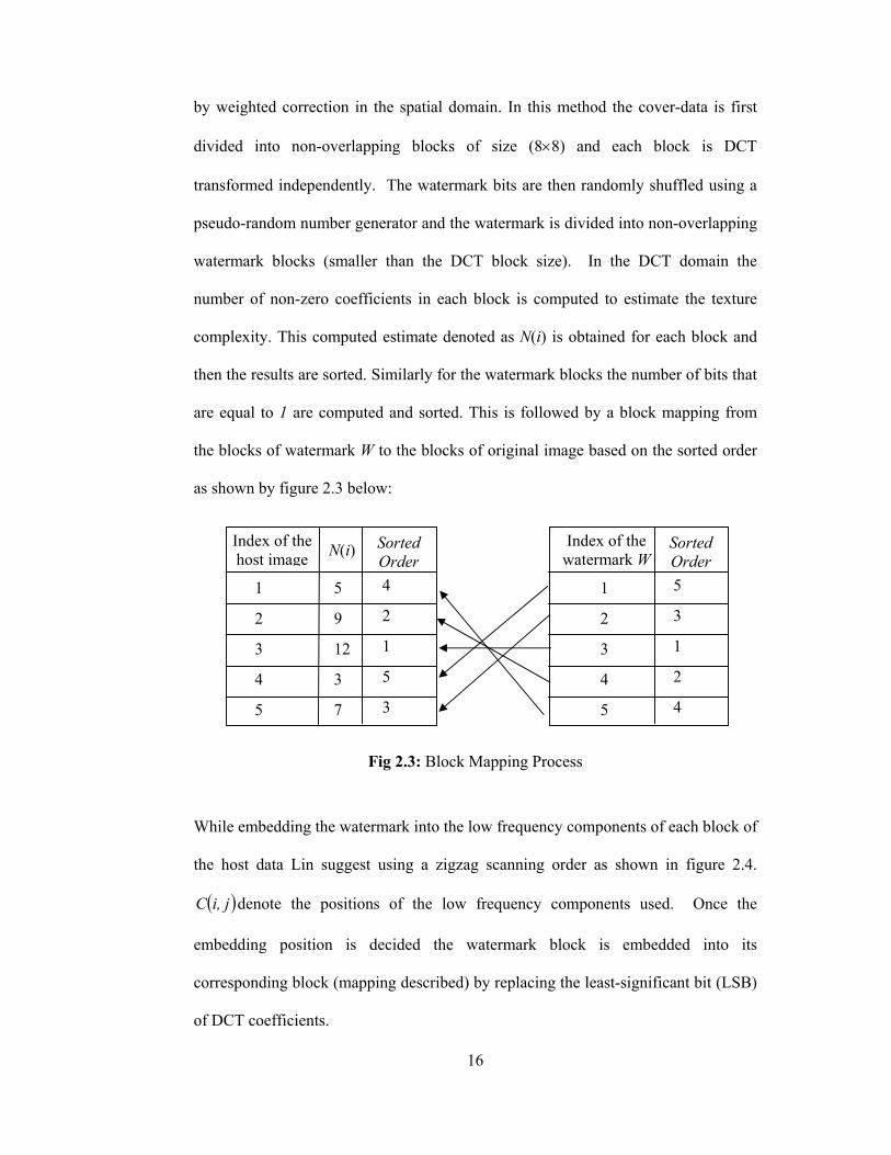
by weighted correction in the spatial domain. In this method the cover-data is first
divided into non-overlapping blocks of size (8×8) and each block is DCT
transformed independently. The watermark bits are then randomly shuffled using a
pseudo-random number generator and the watermark is divided into non-overlapping
watermark blocks (smaller than the DCT block size). In the DCT domain the
number of non-zero coefficients in each block is computed to estimate the texture
complexity. This computed estimate denoted as N(i) is obtained for each block and
then the results are sorted. Similarly for the watermark blocks the number of bits that
are equal to 1 are computed and sorted. This is followed by a block mapping from
the blocks of watermark W to the blocks of original image based on the sorted order
as shown by figure 2.3 below:
Fig 2.3: Block Mapping Process
While embedding the watermark into the low frequency components of each block of
the host data Lin suggest using a zigzag scanning order as shown in figure 2.4.
( )ji,C denote the positions of the low frequency components used. Once the
embedding position is decided the watermark block is embedded into its
corresponding block (mapping described) by replacing the least-significant bit (LSB)
of DCT coefficients.
Index of the host image N(i) Sorted
Order1
2
3
4
5
5
9
12
3
7
4
2
1
5
3
Index of the watermark W
Sorted Order
1
2
3
4
5
5
3
1
2
4

17
DC C(0,1) C(0,2) C(0,3) C(0,4) C(0,5)
C(1,0) C(1,1) C(1,2) C(1,3) C(1,4)
C(2,0) C(2,1) C(2,2) C(2,3)
C(3,0) C(3,1) C(3,2)
C(4,0) C(4,1)
C(5,0)
Fig 2.4: The embedding positions of the low frequency
After all the watermark bits are embedded into the host image, each block is inverse
DCT transformed and the results are combined to obtain the watermarked image.
Finally the difference in gray levels between the original image and the watermarked
image is computed and weighted by a constant q to obtain the magnitude suppression
of the difference image. The final watermarked image is the sum of the original
image and the scaled difference image.
For recovering the watermark data, first each block of the watermarked image is
DCT transformed. The LSB of each modified DCT coefficient is taken and the
permutation on the watermark blocks is reversed. Finally the watermark bits are
reverse shuffled and the watermark is extracted.

18
2.2 Discrete Wavelet Transform Based Watermarking In order to hide watermarks with more energy into a cover data the characteristics of
the HVS must be exploited. From this point of view the discrete wavelet transform is
a very attractive transform because it efficiently models the frequency models for the
HVS. For instance the human eye is less sensitive to noise in high resolution DWT
bands and in the DWT bands having an orientation of 45° (i.e. HH bands).
Besides invisible embedding, the DWT based watermarking methods show superior
robustness to common signal processing operations and high data compression such
as JPEG standard and SPIHT algorithm.
The block diagram of the watermark embedding process is illustrated in figure 2.5:
Fig 2.5: Adaptive Watermarking System
To embed the watermark the original image is first decomposed into 4 levels using
Quadrature Mirror Filter (QMF) wavelet transform [35]. The pyramidal structure of
the decomposed image is depicted in figure 2.6.
FDWTWatermark embedding
process
Weighting function
Watermark
Original Image
Watermarkedimage

19
Fig 2.6: Four level decomposed image
The watermark is embedded in the DWT coefficients using eq. (2.3)
( ) ( )( ) ( ) ( ) ( )( )
( ) ( )
( ) ( )
>⋅+=∗
otherwise
ThresholdyxI
yxI
yxWyxIyxI
sr
sr
srsr
sr
,
,,
,
,1,,
,
,
,,
,
α (2.3)
where ( )srI , is the sub-band resolution level r = 0,1,2,3 with orientation
{ }HHHLLHLLs ,,,∈ sub-band. ( )( )yxI sr ,, is the coefficient value of the
decomposition I at level r, orientation s, and position ( x, y ) within that sub-band.
( ) ( )yxI sr ,,* is the corresponding watermarked coefficient and α is a scaling factor.
While using eq.(2.3) the watermark is selectively embedded into the large
coefficients (higher than threshold) which are located in high frequency subbands
(LH,HL, and HH). These large coefficients represent the detail and edge components
in the image that are less sensitive to human eye.
I0,LH I0,HH
I1,HH
I0,HL
I1,LH
I1,HLI3,HH I2,HL
I2,LH
I3,LL I3,HL
I3,LH

20
The existence of the embedded watermark can be performed by measuring the
normalized correlation between the suspected watermark (preserved by owner) and
the suspected watermarked image coefficients.
Though robust against JPEG compression or SPIHT algorithm, due to the lack of
rotation and translation invariance of the wavelet transform, DWT based
watermarking schemes are still vulnerable to the geometric distortions such as
translation and rotation.

21
CHAPTER 3
3 METHODS FOR ESTIMATING AND RECOVERING FROM
GENERAL AFFINE TRANSFORMS
This section of the thesis first introduces the different types of transformations that
an attacker can apply to a watermarked image. These are transformations that are
intentionally applied so that the proprietary owner who is not aware of the
transformation parameters would find it difficult to invert them before attempting to
take out the watermark. Secondly the chapter discusses the different techniques
proposed in the literature that can be used for affine transform parameter estimation
and some of their shortcomings. Finally the technique which is based on searching
the space of possible affine transformations is explained. In this thesis affine
transform parameters are recovered using this space searching algorithm.
3.1 Affine Transformations An important problem constraining the practical exploitation of watermarking
technology is the low robustness of existing watermarking algorithms against global
geometrical distortions such as translation, cropping, rotation, scaling, change of
aspect ratio, and shearing. Such distortions, that are known as the geometrical attacks
desynchronize the watermark detection and/or decoding. Most of the geometrical
attacks can be uniquely described using the paradigm of general affine transforms,

22
that can be represented by four coefficients d, e, f, g forming a matrix A for the
linear component, plus the two coefficients tx and ty for the translation part tr
:
=
=
y
x
tt
tgfed
Ar
;
(3.1)
The affine transform maps each point of Cartesian coordinates from ( )yx, to ( )yx ′′, ,
according to the expression below:
tyx
Ayx r
+
•=
′′
(3.2)
where • is the matrix product. The tr
component corresponds to the cropping and
the translation which may be estimated based on a cross-correlation as explained in
[29]. In this thesis we will consider only A which can represent a wide variety of
transforms.
3.1.1 Constant scaling factor in both dimensions
Scaling an image in both the x and y directions with the same scale factor are
achieved by transforming the image with the below given affine transform matrix
d
d0
0as shown below:
⋅⋅
=
=
′′
ydxd
yx
dd
yx
00
(3.3)
3.1.2 Changing the aspect ratio of an image by unequal scale factors
Scaling an image in the x and y directions with factors d and g can be achieved as
shown below:

23
⋅⋅
=
=
′′
ygxd
yx
gd
yx
00
(3.4)
3.1.3 Clockwise and anti-clockwise rotations
Rotation of an image can be done either in clockwise or anti-clockwise directions.
Figure 3.1 below shows a clockwise rotation by θ degrees. The affine transform
matrices for clockwise or anti-clockwise rotations are as shown below:
−=
−
=
− θθθθ
θθθθ
cossinsincos
cossinsincos
clockwiseanti
clockwise
Rot
Rot
(3.5)
Fig 3.1: Clockwise Transformation by θ degrees
x
x’
θ
y
y’
( x, y)

24
3.1.4 Shearing
In two dimensions, a simple transformation that maps a pair of input coordinates
[u,v] into a pair of output coordinates [x,y] has the form below:
vyvaux
=⋅+=
(3.6)
Hence a simple shear is a special case of an affine transformation with
=
101
fA .
3.2 Log-Polar Mapping
In [23] a method that embeds the watermark in a rotation, scale, and translation
invariant domain using a combination of DFT and a log-polar map (LPM) is
proposed. First the magnitude of the DFT is calculated to obtain a translation
invariant domain. Afterwards, for every point ( )vu, of the DFT amplitude a
corresponding point in the LPM, ( )θµ, , is calculated as:
( )( )θθ
µ
µ
sincos
eveu
=
= (3.7)
The origin of the log-polar mapping is chosen at the center of the image. Any
rotation in the watermarked image converts into a shift in the horizontal axis. The
magnitude of this shift exactly equals the rotation angle. Similarly any scaling in the
25
image converts into a shift in the vertical axis. The magnitude of this shift exactly
equals the log of the scaling factor.
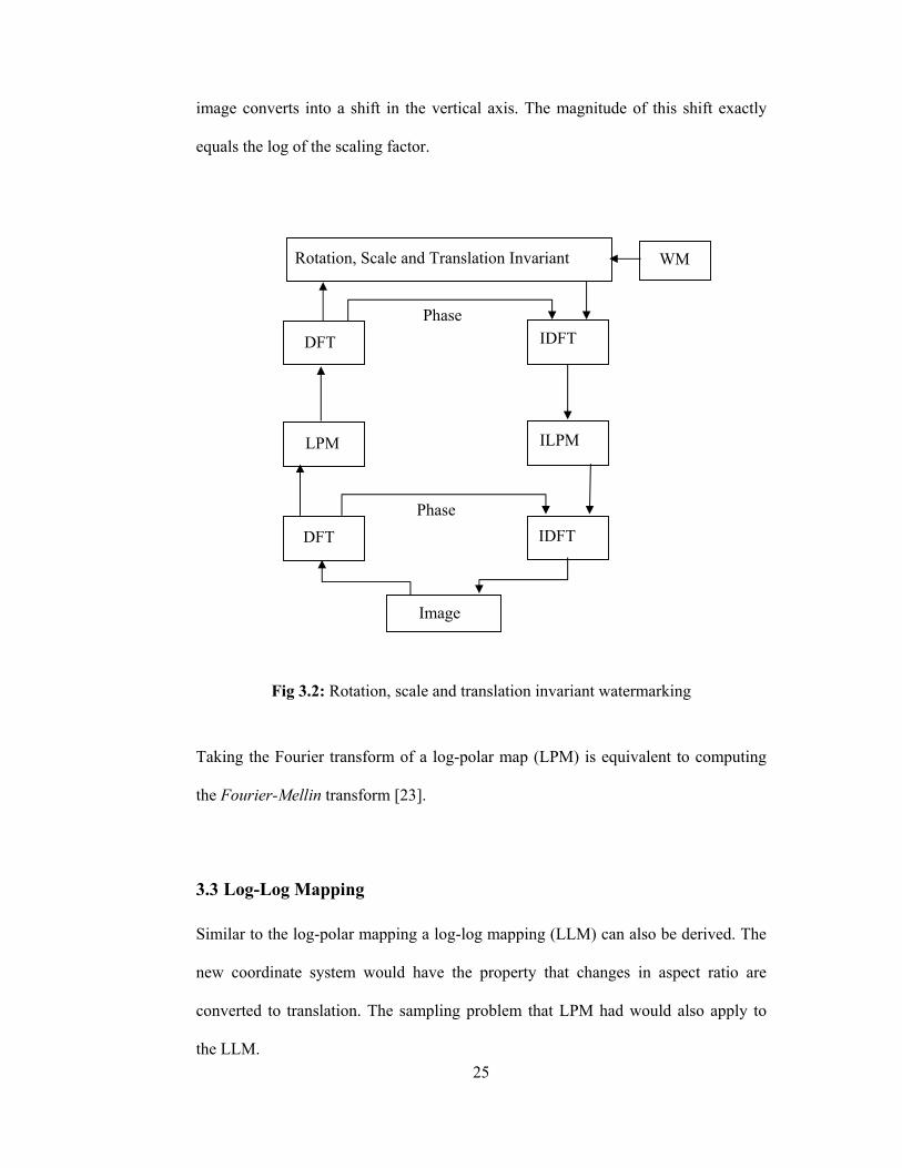
Fig 3.2: Rotation, scale and translation invariant watermarking
Taking the Fourier transform of a log-polar map (LPM) is equivalent to computing
the Fourier-Mellin transform [23].
3.3 Log-Log Mapping
Similar to the log-polar mapping a log-log mapping (LLM) can also be derived. The
new coordinate system would have the property that changes in aspect ratio are
converted to translation. The sampling problem that LPM had would also apply to
the LLM.
Image
IDFT
ILPM
IDFT DFT
DFT
LPM
Phase
Phase
Rotation, Scale and Translation Invariant WM

26
3.4 RST Invariant Phase Only Filtering Method
This method proposed by Zheng in [30], combines the log-polar mapping with a
phase only filtering method in order to come up with a rotation, scaling, and
translation invariant digital watermarking scheme. The relationship between an
image ( )yxI , and its rotated and scaled version ( )yxI ,1 can be written as follows:
( ) ( ) ( )( )ααβααβ cossin,sincos, 01 ⋅+⋅−⋅+⋅= yxyxIyxI (3.8)
where β and α represent the scaling and rotation parameters. If we then take the
Fourier transform of the two images their spectrums are related as:
( ) ( ) ( )( )ααβααββ cossin,sincos, 110
21 ⋅+⋅−⋅+⋅= −−− vuvuIvuI (3.9)
If equation (3.9) is re-written using log-polar coordinates, ( )θ= µ coseu and
( )θ= µ sineu , then the magnitude of the Fourier spectrum can be written as:
( ) ( ) ( )( )
( ) ( ) ( )( )αθβµβθµ
αθβαθββ µµ
−−=
−−=
−
−−−
,ln,
sin,cos,
02
1
110
21
II
eeIvuI
(3.10)
3.5 Template Embedding in the Fourier Domain
This method consists of embedding a watermark in the DFT domain. The watermark
is composed of two parts: a template and a spread spectrum message containing the
information or payload. The template contains no information in itself but is
absolutely necessary for detecting the transformations undergone by the image. Once
detected, the transformations are inverted and then the spread spectrum signal is

27
decoded. The payload contains information relating to the owner of the image or a
serial number. Unlike algorithms which use log-polar or log-log mapping, the
technique here searches the space of possible affine transformations. Since a full
search of the entire space is not practical the search space is carefully pruned and the
transformations can then be detected reasonably quickly.
3.5.1 Embedding the Synchronization Template
The template embedded contains no information and is purely used to recover the
transformations in the image. The template to insert consists of two straight lines
each crossing through the origin and set at the two angles 1θ and 2θ . As proposed in
[24], there would be eight points per each template line. These points are distributed
uniformly in the DFT domain with radii varying between 1tf and 2tf . Thirty-two
template points (8 original and 8 symmetric per each line) have been proven to
provide a good balance between visual quality and robustness. The two angles
should be chosen such that 21 θθ − is less than 90°. The template line with a larger
angle is referred to as the reference line.
The strength of the template at each point ( ) ( )θθ= sin,cos, iiii RRyx is adaptively
determined. In [26], Pereira showed that inserting points at strength equal to the local
average value of the DFT points plus three standard deviations would yield a good
compromise between visibility and robustness during decoding. The local mean can
be taken as the average magnitude of the 120 neighborhood pixels of ( )ii yx , and
standard deviation is that of the Fourier transformed watermarked image.
28
3.5.2 Template Detection The main idea in the detection of the template is to exploit the fact that the template
points have been embedded along two lines that go through the origin. An image,
which has undergone a linear transformation, will have undergone the inverse linear
transformation in the DFT domain. Furthermore, for a linear transformation a line
going through the origin will be transformed into a corresponding line also going
through the origin. Some constant K will relate the radii of the new points to the radii
of the old points as below:
opnp rKr ⋅= (3.11)
The algorithm for detecting the two template lines in a transformed image is as
described below:
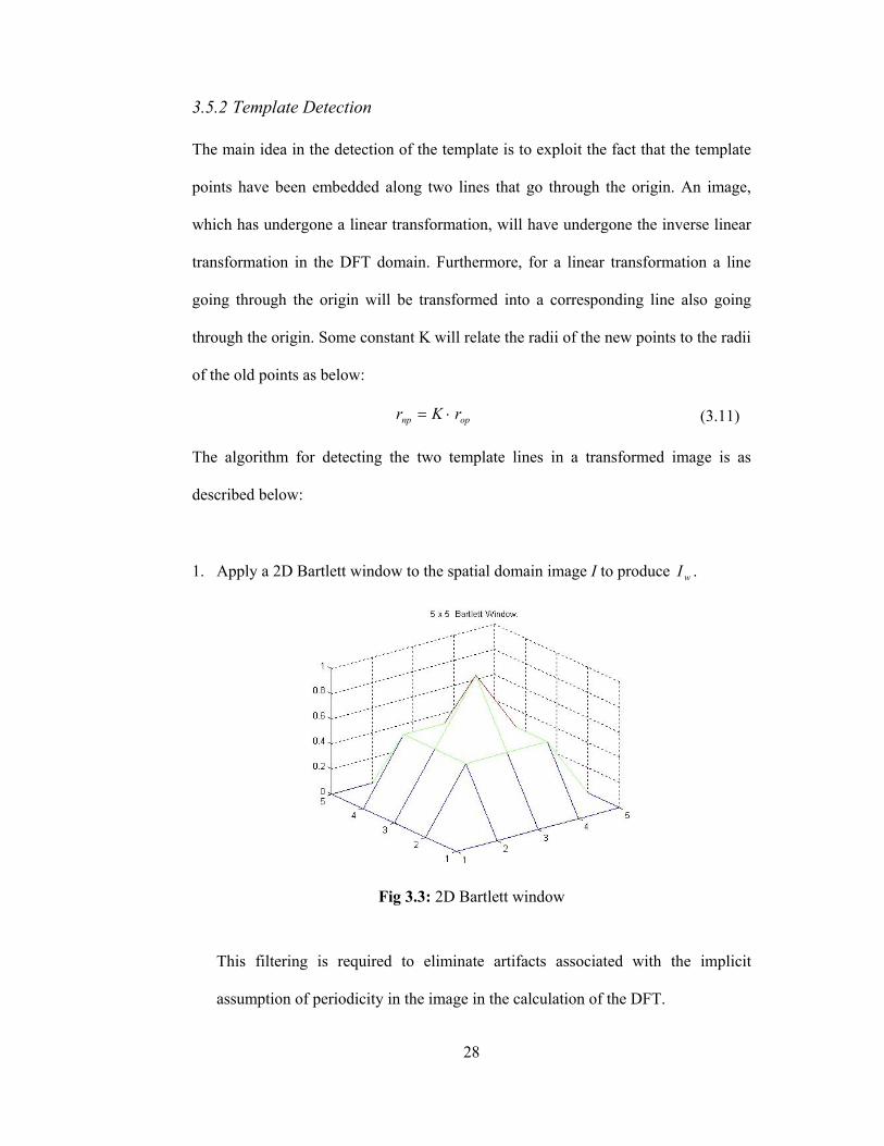
1. Apply a 2D Bartlett window to the spatial domain image I to produce wI .
Fig 3.3: 2D Bartlett window
This filtering is required to eliminate artifacts associated with the implicit
assumption of periodicity in the image in the calculation of the DFT.

29
2. Calculate the fast Fourier transform (FFT) of the image either at (512×512) or at
(1024×1024) padded resolution.
3. Extract the positions of all the local peaks ( )yixi pp , in the image. These peaks
satisfy the following condition:
01 ≥⋅−− StdkMeanLocalMagnitude (3.12)
where the magnitude is the value at ( )yixi pp , and Local Mean is the average of
120 neighboring peaks. The template detection strength is denoted by k1. This
value is adaptively increased until the number of local peaks is less than a pre-
determined threshold.
4. Sort the peaks by angle and divide into bN equally spaced bins by angle.
5. For both template lines perform the following:
For each of the bN equally spaced bins search for a K where
maxmin KKK << such that at least mN points match between the points ir which
are the radial coordinates of the points in bin i (where bNi K1∈ ) and the
Tjr which are the radial coordinates of the template along line j (where 2,1∈j ).
Two points are assumed to match if thresholdrKr Tji <⋅− . If at least mN points
match we store the set of matched points.
6. For all combinations of sets of matched points choosing one set from those
corresponding to template line Line-1 and a second set corresponding to template
line Line-2. Calculate the linear transformation A such that the mean square
estimation error below is minimized:

30
2
22
2121
11
1111
'2
'2
'21
'21
'1
'1
'11
'11
#1
T
ll
ll
T
ll
ll
yx
yxyx
yx
yx
yxyx
yx
Aofmatches
MSE
−
= (3.13)
7. Repeat step-6 adding 180° to the angles in the set of matched points
corresponding to Line-1 of template.
8. Choose the A that minimizes the mean square error.
9. If the minimized error is less than the detection threshold, Td , it implies that the
watermark is detected.

31
CHAPTER 4
4 ROBUST HYBRID METHOD RESISTANT TO COMPRESSION AND GENERAL AFFINE TRANSFORMS
In this thesis since our main objective is to formulate a watermarking algorithm that
will be resistant both to compression and general affine transforms we propose
working on a hybrid model. This model will embed a grayscale image as watermark
either in grayscale or color cover data and recover the embedded information after
Stirmark attacks.
In [18], Huang, Shi, and Shi Y. have suggested embedding Gaussian distributed
random numbers in DC components of the (8×8) blocks belonging to the entire DCT
transformed image. This approach is known to provide nearly perfect resilience
against compression and image tempering since the watermark is embedded in the
lowest frequency components. Any attempt to remove the watermark by playing with
the highest energy components will easily be noticed since such attempts will also
alter the cover data.
Even though the DC-component based watermarking scheme is resistant against
compression it still suffers from general affine transformations. A one degree
rotation either in clockwise or anti-clockwise directions or a scaling of the image to
different proportions will result in failure of the watermark detection. To avoid this
failure in the recovery phase we propose to combine an affine transform resistant

32
method proposed by Pereira and Pun [25, 26] with the DC component watermarking
proposed by Huang.
Pereira and Pun’s algorithm suggests embedding two template lines in the spectrum
of the cover data which can later be utilized for synchronization. Each line is to have
eight points (peaks in frequency domain) which should be inserted to the mid-band
frequencies of the DFT transformed image. After an affine transform attack the aim
will be to detect these template peaks in the spectrum of the attacked image and
estimate the scale and rotation parameters in order to invert the affine
transformations undergone by the image.
A block diagram of the hybrid watermarking scheme we propose is as shown in
figure 4.1 (a) and (b) below.
(a) Watermark and Synchronization Template Embedding
DC-component based Watermark
Embedding
DCT IDCT DFT
Template
Template Embedding
IDFT
Watermark
Original image
Watermarked image

33
(b) Template synchronization and Watermark Detection
Fig 4.1: Block Diagram of the Hybrid Watermarking System Proposed
4.1 DC Components Based DCT Domain Watermarking
In [18], Huang states that traditional DCT watermarking algorithms would use only
the mid-band frequencies for watermark embedding, and points out that many
researchers would explicitly exclude the DC components in order to avoid
watermark perceptibility. Cox et al [2], has suggested that watermarks should be
placed in perceptually significant regions of an image if it is to be robust. Jiwu
Huang’s quantitative analysis on the magnitude of DCT components has recently
showed that DC components have much larger perceptual capacity than any AC
component which would make them a better candidate for watermark embedding.
Image watermarking can be viewed as superimposing a weak signal (watermark)
onto a strong background signal (cover data). Watermarks can be detected by HVS if
they exceed the detection threshold of the HVS. According to Weber [38], the
detection threshold of visibility for an embedded signal is proportional to the
magnitude of the background signal. Compared with AC components, DC
Attacked Image DFT DCT IDFT
Template Detection, Synchronization &
Inverting Affine Transformations
WatermarkDecoding
Detected Watermark

34
coefficients can be modified by a much larger quantity due to having a large peak in
their magnitude distribution.
Based on his findings, Huang proposed an adaptive watermarking algorithm that
would use luminance and texture masking (spatial masking) to keep the watermark
embedded invisible. Before applying this adaptive masking, the image ( )yxf , is split
into K non-overlapping blocks with each block having a size of (8×8):
( ) ( ) 8,0,,1
0
1
0<′′≤′′==
−
=
−
=yxyxfByxf
K
kk
K
kk UU (4.1)
where Bk denotes the kth block and k = 0,1,…,(K-1). After the splitting operation each
block is classified having either weak texture (S1) or strong texture (S2) using
equation 4.2. Because the HVS is more sensitive to a gray-level change in weak
texture in comparison to strong texture, the strength of the watermark should be
stronger in the strong texture blocks and weaker in the weak texture blocks. This is
what is referred to as texture masking.
( )
otherwiseTByxyxeof
SBSB k
k
k 1
2
1 }),(,0,{#, <∈≠
∈∈
(4.2)
#of{⋅} denotes the number of points satisfying the specified condition, ( )yxe , is a
binary edge map of ( )yxf , obtained by applying a gradient operator followed by a
threshold operation. Equation 4.2 results in a weak texture if the edge point density is
below the threshold and strong texture if the edge point density is above it. Some
classified blocks are shown in figure 4.2. Weak texture blocks are shown on the left
side and strong ones on the right.

35
Fig 4.2: Texture classified blocks
After block classification each (8×8)block is DCT transformed,
( ) ( ){ } 8,0,, <≤′′= vuyxfDCTvuF kk (4.3)
The watermark bits ( , ) { ,0 }iW x y x i K= ≤ < (approximately 1/64 of the cover-data to
be watermarked) will be embedded by modifying the DC coefficients of each
corresponding block as:
( ) ( ) ( )( )
==⋅+⋅
=′otherwisevuF
vuifxvuFvuF
k
kkk ,
01,,
α
(4.4)
In eq. (4.4), α denotes the scaling factor. Since the strength of embedded signals is
proportional to the values of DC coefficients, which is proportional to the average
brightness information of the background, the embedding formula has automatically
utilized the luminance masking, and texture masking is incorporated by changing
scaling factor adaptively. α is experimentally selected to be 6×10⁻³ for weak textured
blocks, and 15 × 10-3 for strong textured blocks.
The spatial domain watermark embedded image can be obtained by IDCT
transforming each block and joining them back.

36
( ) ( ){ } 8vu,,0vu,FIDCTyx,f kk
<≤=U (4.5)
The extraction process of the watermark relies on computing a correlation based
similarity value. If we assume that ( )vuFk ′′,* denotes the DCT coefficients of the
corrupted watermarked image in block Bk, and W* denotes the corrupted watermark
then equation 4.6 can be used for the extraction of W* where xi* denotes the
corrupted version of xi.
( ) ( ){ }U kixWW
FFW
ik
kkk
<≤==
−=
0
0,00,0***
**
(4.6)
In order to decide whether a watermark exist in an attacked image, the similarity
factor ρ between *W and W is determined
1*
* 01
* 2
0
( . )( , )
( )
n
i ii
n
ii
x xW W
xρ
−
=
−
=
=∑
∑ (4.7)
If the similarity value ( )WW ,*ρ is greater than a pre-selected threshold Th, then it
can be assumed that a watermark exists in the corrupted image.
4.2 Template Addition in DFT Domain The watermarking algorithm described in section 4.1 is quite robust against
compression but it still is not robust against geometrical attacks such as rotation and
scaling because of the misalignment between embedded coefficients and the original
watermark bits. To gain robustness against geometrical attacks, it is necessary to add

37
a template into the watermarked image so that the synchronization problem can be
solved.
A template consists of a series of uniformly or randomly distributed local peaks
which are inserted into the cover data in the spectrum domain. Template itself does
not contain any information and is merely a tool used to recover possible
transformations undergone by the watermarked image. Once detected, these
transformations can be inverted by reverse transforming the image by the estimated
affine transform parameters.
Various approaches for template addition are discussed in [24], [25] and [26]. The
template is generally inserted in the Discrete Fourier Domain. Because of the
rotation and scaling properties of the Fourier Transform, the local peaks will rotate in
the case of a rotation and they will reciprocally scale in the case of image scaling. By
calculating the rotation and scale parameters for the local peaks detected from the
attacked image it is possible to re-orient the attacked image and then decode the
watermark previously embedded.
The local peaks belonging to the template are not affected from any translation
because shifts in spatial domain only cause a linear shift in the phase component and
the magnitude components of Fourier transformation do not get affected. Therefore
inserting the template points in the DFT domain makes the algorithm naturally robust
against translations.

38
In this work, the template is added to a (512 × 512) stego image. The peaks that form
the template lines are inserted in the DFT mid-band frequencies. The first peak on
each line is placed at a radius of 120 and the last one at 190. As depicted in figure 4.3
(b) after taking the discrete Fourier transform the strongest components of the DFT
will be in the outside corners. We shift them to the center in order to facilitate
template addition and detection.
(a) (b) (c)
Fig 4.3: Original LENA image and log of magnitude of DFT
(a) Stego Lena image (b) log of the magnitude of DFT (c) log of the
magnitude of DFT with strongest components shifted to the center.
While inserting the template points, both the highest and lowest frequencies have
been avoided in order to gain robustness against compression and to preserve
invisibility of the embedded template since template contains local peaks with fairly
large amplitudes. As stated in [24] and [25] two template lines each with 8 peaks
have been adopted. Due to the symmetry property of the DFT magnitude the entire
template will contain a total of 32 local peaks. The inter distance between template
points have been selected as 10 since it has been shown in [25] that this amount of

39
separation would prevent blurring of the magnitudes of local peaks that may result
from geometrical operations.
The strength of the template at each point ( , ) ( cos , sin )i i i ix y R Rθ θ= is adaptively
determined as:
where, LocalMean is the average magnitude of the 120 neighborhood pixels of
( )ii yx , , std is the standard deviation of the Fourier transformed image, and α is the
embedding template strength. We have seen experimentally that a good compromise
between visibility and robustness may be obtained for α in the range 2-3.
It should be noted that at least two template lines are required in order to resolve the
ambiguities that arise from the magnitude symmetry of the DFT. The main idea in
the detection of the template is to exploit the fact that the template points have been
embedded along two lines that go through the origin and for a linear transformation a
line going through the origin will be transformed into a corresponding line also going
through the origin.
Details of how the affine transform parameters should be estimated are thoroughly
discussed in section 3.5. Figure 4.4 below shows the detected local peaks (including
the template) from the DFT magnitude of the attacked image for rotation and scaling
attacks.
LocalMean stdα+ × for i=1,…,8 (4.8)

40
(a) rotation attack by 25°

41
(b)
Fig 4.4: Detected local peaks satisfying equation (3.12)
In figure 4.4, only half of the plane is searched for local peaks since the remaining
half plane is going to be symmetric. The uniformly spread template points are also
among the detected peaks.

42
CHAPTER 5
5 SIMULATION RESULTS
This chapter contains the simulation results which are presented in four sections.
Section 5.2 is about discrete cosine transform domain watermarking using the mid
band frequency components. Section 5.3 covers DCT domain DC-coefficient
watermarking of both grayscale and color images. Robustness of the DC-component
watermarking against JPEG compression and cropping is tested. Section 5.4
simulates the template based DFT domain watermarking technique proposed by
Pereira and evaluates robustness against rotation, scaling, and aspect ratio changes.
Finally Section 5.5 gives results about the proposed hybrid algorithm which
combines DCT domain DC-coefficient watermarking and template based DFT
domain watermarking techniques. All simulation models are implemented using the
software package MATLAB.
5.1 Standard Test Images The evaluation of the DCT domain DC-component based watermarking and the
template based DFT domain watermark synchronization approaches have been done
using standard grey level and color images obtained from
http://decsai.ugr.es/cvg/CG/base.htm. In this database there exist 49 different
grayscale test images each of size (512 × 512). In this thesis we only used a number

43
of these test images. The grayscale and color images used are depicted in figures 5.1
and 5.2 respectively.
(a)Barbara (b)Butterfly (c)Avion
(d)Mandrill (e)Lena (f)Peppers
(g)Goldhill (h)Boat (i)Owl
Fig 5.1: Grayscale Standard Test Images

44
(a)Avion (b)Mandrill
(c)GreenPeace (d)Lena
Fig 5.2: RGB Standard Test Images
5.2 Discrete Cosine Transform Domain Watermarking As explained in section 2.1.1 we used the mask in eq. (5.1) for selecting the desired
mid-band frequency components in the DCT domain for watermark embedding. A
size (50×20) binary watermark image reading “Copyright” has been used as the
authentication data. The watermark has been embedded into grayscale images of
Lena, Butterfly, and Barbara and later extracted. Watermarked images, their PSNR
values and the extracted marks from each image are shown in figure 5.3.

45
=
0000000000000001000000110000011100001111000111100011110001111000
_ maskmidband (5.1)
Lena Butterfly Barbara (a) Originals
PSNR =36.3857 dB PSNR = 35.1400 dB (b) Watermarked Images
PSNR= 36.3151 dB
(c) Extracted Watermarks
Fig 5.3: DCT domain watermarking using mid-band frequency components
Binary watermark of size (50 × 20) used.

46
Table 5.1: PSNR values for extracted watermarks from JPEG
compressed watermarked images PSNR of extracted watermark JPEG Quality
Factor LENA BARBARA BUTTERFYL 95 20.4576 dB 13.3724 dB 23.9794 dB 75 19.5861 dB 13.1876 dB 23.9794 dB 55 19.2082 dB 12.2915 dB 23.0103 dB 35 13.2790 dB 10.1323 dB 14.8149 dB
Fig 5.4: Robustness against JPEG compression using mid-band DCT watermarking
Table 5.1 and figure 5.4 above show the JPEG compression resilience of the mid-
band DCT watermarking scheme for three different grayscale images. Namely: Lena,
Barbara and Butterfly. Though there are differences between the results attained
using the three test images, still the PSNR of the extracted images are low when
compression applied is high.

47
5.3 DCT domain DC-Component Based Watermarking In this section the grayscale images have been marked using the DCT domain DC-
components previously discussed in section 3.1. The payload, a (32 × 32) gray scale
image, has been embedded in some of the grayscale images in figure 5.1 and later
recovered. The watermark embedded images with their corresponding PSNR values
are shown in figure 5.5, whereas the recovered versions of the embedded payload are
as depicted in figure 5.6.
PSNR=40.1896 dB (a) Mandrill
PSNR=33.2404 dB (b) Barbara
PSNR=33.6505 dB (c) Goldhill
PSNR=43.6416 dB (d) Lena
PSNR=43.4019 dB (e) Peppers
Fig 5.5: DC-Component Based DCT Domain Watermarked Images
In figure 5.5, it is seen that PSNR values of watermarked images are not close to
each other. Images that are composed mostly of high frequency components, i.e.
Barbara and Goldhill, the magnitude of the DC coefficient is lower and hence PSNR
is also comparatively lover. On the other hand images that are composed mostly of

48
low frequency components, i.e. Lena, Peppers and Mandrill, the magnitude of the
DC coefficient is higher which implies higher perceptual capacity and also the
texture is stronger. These two factors lead to higher PSNRs in comparison to Barbara
and Goldhill.
original from (a) from (b) from (c) From (d) from (e)
Fig 5.6: The original and extracted watermarks from stego grayscale images
The PSNR values computed for the extracted marks in comparison to the original
mark are as shown in table 5.2. In comparison to results in table 5.1 the extracted
watermarks using the DCT domain DC-component based watermarking technique
are much higher.
Table 5.2: PSNR values for watermarks extracted from grayscale images
Cover Data PSNR (dB) of watermark extracted Baboon 59.1275 Barbara 55.8285 Gold Hill 55.8045 Lena 58.4834 Peppers 54.9360
5.3.1 DCT domain DC-Component Based Watermarking of color images In this section we have extended the use of DCT domain DC-component based
watermarking technique from grayscale to color images depicted in figure 5.2. Since
it is a know fact that the human eye is less sensitive to changes in the blue band the
blue component of the RGB images have been used for embedding the watermark.
As payload a (64 ×64) grayscale image reading “EMU EEE 2006 Fahri” was used.

49
PSNR= 33.9314
(a) Avion PSNR= 52.0268
(b) Mandrill
PSNR=46.8728 (c) Green Peace
PSNR= 32.6622 (d) Lena
Fig 5.7: PSNR for DC-component based watermarked color images
The watermark embedded images with their corresponding PSNR values are shown
in figure 5.7, and figure 5.8 show the recovered watermark from each of the four
stego images. The PSNR values computed for the extracted marks in comparison to
the original mark are also given in table 5.3.
Original from (a) from (b) from(c) from (d)
Fig 5.8: Watermarks extracted from stego color images

50
Table 5.3: PSNR values for watermarks extracted from color images
Color Cover Data PSNR (dB) of watermark extracted Avion 58.5708 Baboon 60.3032 Green Peace 59.7603 Lena 56.6957
5.3.2 Robustness Test against JPEG compression To assess the robustness against JPEG compression the DCT domain DC-component
based watermarking algorithm has been tested using the color images of the previous
subsection. The JPEG quality factor was introduced using the “Imwrite” command of
MATLAB and values were selected from the range 10-90. The PSNR values for the
extracted watermarks have been computed for all the images and are as seen in figure
5.9.
Fig 5.9: Robustness of DC-coefficient watermarking against JPEG compression
In comparison to the DCT domain mid-band component based watermarking, it is
clear that the DC-component based watermarking is much more robust against JPEG

51
compression. A PSNR of 35-38 dB is still possible for the extracted watermark at a
Q-factor value of 30.
5.3.3 Cropping Resilience Test In order to make the watermarking more robust against cropping it is possible to
embed the payload multiple times at different locations. In this work we embedded
four copies, one to each quarter of the image as depicted by figure 5.10.
Fig 5.10: Watermarking using multiple copies of the authentication data
Figure 5.12 and 5.13 shows the attacked image after all-round and diagonal
cropping. The all-round cropping is a severe attack since 75 % of the watermarked
image will be removed. Even under such a severe attack it is still possible to recover
the embedded mark fully by combining the extracted parts shown in figure 5.12 (d)-
(g) as below:
Fig 5.11: Re-assembling the authentication data from extracted parts

52
(a) (b) (c)
(d) (e) (f) (g)
Fig 5.12: All-round Cropping
(a) (b) (c)
(d) (e) (f) (g)
Fig 5.13: Diagonal Cropping
5.4 Template based DFT domain watermarking technique An important problem constraining the practical exploitation of watermarking
technology is the low robustness of existing watermarking algorithms against
53
geometrical distortions such as cropping, rotation, scaling and change of aspect ratio.
Sections below test the template based hybrid watermarking algorithm under
different attacks.
5.4.1 Detecting angle of Rotation
The algorithm for calculating the rotation angle depends on detecting the two
template lines from the Fourier transformed version of the attacked image. After the
extraction of the local peaks, their positions are firstly mapped to polar coordinates
and then peaks are sorted by angle into 360 equally spaced bins. From these angle
bins those with at least five peaks that match the radius patterns of one of the two
template lines is accepted as a matched line. Finally from all combinations of sets of
matched lines only two satisfying an angle difference of 21 θθ − is chosen.
During simulations Barbara and Butterfly images were intentionally rotated by 65
and 25 degrees and the above described algorithm applied in order to find the correct
template lines. As depicted in figures 5.14 and 5.15 the algorithm is successful in
finding the rotation angle and correcting the orientation of the attacked image.

54
(a) Original (b) Template Embedded (b) Attacked
(d) peak map (b) Restored Image
Fig 5.14: 65° rotation attack

55
(a) Original (b) Template Embedded (b) Attacked
(d) peak map (b) Restored Image
Fig 5.15: 25° rotation attack
5.4.2 Constant Scaling in both directions For scaling tests a watermarked and template added version of the (512 × 512) image
of ROBIN was used. Two different types of scaling were applied. In the first type the
image was scaled in both the horizontal and vertical directions using a fixed scaling
factor to keep the aspect ratio same. Results obtained using the method described in
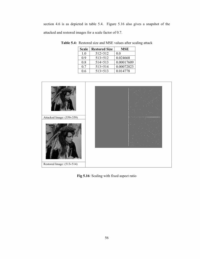
56
section 4.6 is as depicted in table 5.4. Figure 5.16 also gives a snapshot of the
attacked and restored images for a scale factor of 0.7.
Table 5.4: Restored size and MSE values after scaling attack
Scale Restored Size MSE 1.0 512×512 0.0 0.9 513×512 0.024668 0.8 514×513 0.000176090.7 513×514 0.000728230.6 513×513 0.014778
Attacked Image: (359×359)
Restored Image: (513×514)
Fig 5.16: Scaling with fixed aspect ratio
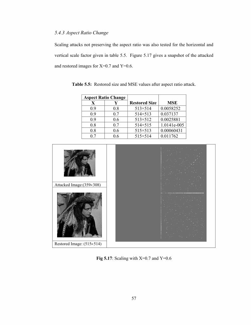
57
5.4.3 Aspect Ratio Change Scaling attacks not preserving the aspect ratio was also tested for the horizontal and
vertical scale factor given in table 5.5. Figure 5.17 gives a snapshot of the attacked
and restored images for X=0.7 and Y=0.6.
Table 5.5: Restored size and MSE values after aspect ratio attack.
Aspect Ratio Change
X Y
Restored Size
MSE 0.9 0.8 513×514 0.0058252 0.9 0.7 514×513 0.037137 0.9 0.6 513×512 0.0025881 0.8 0.7 514×515 1.0141e-005 0.8 0.6 515×513 0.00060431 0.7 0.6 515×514 0.011762
Attacked Image:(359×308)
Restored Image: (515×514)
Fig 5.17: Scaling with X=0.7 and Y=0.6

58
We note that in either case the image restored does not have the same dimensions as
the original watermarked image before the attack. The small changes in aspect ratio
are incurred as a result of rounding errors.
5.5 Hybrid Watermarking Technique In section 5.3 it was shown that the DC-component based Discrete Cosine Transform
domain watermarking is very efficient against JPEG compression. However the
accuracy of the template based DFT domain technique described by [25] in
estimating the affine transform parameters for scaling is not perfect. The error
incurred is due to the rounding that takes place when an image is re-scaled in spatial
domain using non-integer scale factors. Step-5 of the template detection algorithm of
section 4.6 requires computing the absolute difference shown in equation (5.2). For a
small threshold value it will be possible to obtain a good estimate of K (the
reciprocal of the scaling factor) if the absolute difference is smaller than a selected
threshold value.
thresholdrKr Tji <⋅− (5.2)
For instance a size (512×512) digital image that is scaled down by a factor of 0.6 will
assume the size (308×308) since the grid is composed of integer valued locations
(512*0.6 = 307.2). As shown in table 5.6 a point on the original template at
coordinates (72,96) may map into one of two sets of coordinates after taking the
transform of the attacked image zero padded to the original image size. The reverse
of scaling factor 0.6 is 1.66666666 so with K at three digits accuracy after the
decimal point and rTj=120 there will be two different values for the absolute

59
difference. One of these will satisfy the threshold constraint but the other will not do
so stopping the convergence of affine transform parameters to the correct ones.
Table 5.6: Effect of rounding errors on the absolute difference value
Coordinates of a template point in DFT transformed original image
Coordinates for the corresponding template point after transforming the padded attacked image (119.52 , 159.36) (119.68 , 159.58) After rounding (120 , 159) 2009.1991 =⇒ rad (120 , 160) 2002 =⇒ rad
(72,96)
K= 0.5 : 0.001: 2 Current K = 1.666 Threshold =0.09
09.07191.092.1992009.199
09.008.092.199200
>=−
<=−
The proposed hybrid method can be demonstrated for rotation, cropping, and scaling
attacks.
We demonstrated the applicability of the hybrid watermarking method using two
color test images. Firstly a (64×64) watermark was inserted in the blue channel of the
RGB images and then the synchronization template was embedded in their respective
red channels. Afterwards the watermarked and template embedded images were
intentionally rotated by -35 and 15 degrees respectively. A MATLAB program
detected the rotation angle and the watermark embedded was then extracted from the
restores images. The results obtained are depicted in figures 5.18 and 5.19.

60
Original Watermark to insert
Watermark in blue channel
Watermark and Template Embedded
attacked Restored -35 Extracted watermark
Fig 5.18: Proposed Hybrid Watermarking applied with a 35 degree attack
Similarity values computed for the extracted watermarks are 0.9425 for
GREENPEACE test image and 0.9573 for the MANDRILL. The only discrepancy is
that some of the high frequency components of the original cover data can also be
observed in the extracted watermarks. A possible solution will be to lowpass filter
the output or to pass it through a median filter. However in general we can say that
the proposed method works well.

61
Original Watermark to insert
Watermark in blue channel
Watermark and Template
Embedded
Attacked image Restored 15 Extracted watermark
Fig 5.19: Proposed Hybrid Watermarking applied with a -15 degree attack
For scaling tests a watermarked and template added version of the (512 × 512)
images of LENA and AVION were used. Two different types of scaling were
applied. In the first type the image was scaled in both the horizontal and vertical
directions using a fixed scaling factor of 0.7 to keep the aspect ratio same. Scaling
attack not preserving the aspect ratio was also tested for the horizontal and vertical
scale factors of X = 0.9 and Y = 0.7. In either case as can be seen from figure 5.20
the extraction of the inserted watermark is possible.

62
Attacked Image: (359 × 359) (a)
Restored Image:(511 × 513) (b)
Extracted Watermark
(c)
Attacked Image: (461×359) (d)
Restored Image: (511×512) (e)
Extracted Watermark
(f)
Fig 5.20: Recovery from Scaling Attacks

63
CHAPTER 6
6 CONCLUSIONS & FUTURE WORK
The work carried out indicates that the DC-component based discrete cosine
transform domain watermarking technique is much more robust against JPEG
compression when compared to the mid-band frequency based DCT domain
watermarking technique.
Embedding the authentication mark multiple times in different location in the cover
data makes the watermarking much more robust against cropping. Even with all
round cropping where 75% of the image is removed it is still possible to get the full
mark by re- ordering the extracted parts. The only disadvantage here may be that the
size of the payload will be smaller when multiple copies are to be embedded.
The use of a synchronization template in the DFT domain provides a tool for
estimating and correcting the affine transformations that the image may have been
subjected to.
As demonstrated in section 5.5 the proposed hybrid watermarking algorithm is robust
against compression, rotation translation and scaling attacks. The only problem faced
is that recovery from scaling attacks is not perfect due to the rounding errors as
previously explained. Hence the future work will try to engineer a way in better
estimating the affine transform parameters for scaling.

64
Also for decreasing the computational cost of template matching algorithm, a future
work is suggested by Pereira; using a pruned exhaustive search instead of binning by
angle, and detecting local peaks by taking local maximum of every 5×5 window in
the DFT domain instead of a harmful search.
65
REFERENCES
[1] Kundur D., Hatzinakos D., “A robust digital image watermarking method
using wavelet-based fusion,” Int. Conf. on Image Processing, Vol. 1, Oct 1997, pp. 544-547.
[2] Cox I. J., Kilian J., Leighton F. T., & Shamoon T., “Secure Spread Spectrum
Watermarking for Multimedia,” IEEE Transactions on Image Processing, Vol. 6, No: 12, Dec 1997, pp. 1673-1687.
[3] Tirkel A.Z.., Rankin G. A., Schyndel R.G. van, Ho W.J., Mee N.R.A., and
Osborne C.F., “Electronic Watermark,” In Dicta-93, Dec 1993, pp. 666-672. [4] Bender W., Gruhl D., and Morimoto N., “Method and apparatus for data
hiding in images,” U.S. Patent # 5689587, 1996. [5] Goffin F., Delaigle J.F., De Vleeschouwer C., Marc B., and Quisquater J.J.,
“A low cost perceptive digital picture watermarking method,” Storage and Retrieval for Image and Video Database, Vol. 3022, Feb 1997, pp. 264-277.
[6] Kutter M., Jordan F., & Bossen F., “Digital signature of color images using
amplitude modulation,” Proc. of SPIE-EI 97, Feb 1997, pp. 518-526. [7] Cox I. J., Miller M. L., and McKellips A. L., “Watermarking as
Communications with Side Information,” Proc. of IEEE, Vol. 87, No: 7, July 1999, pp. 1127-1141.
[8] Ho A.T.S., Jun S., Soon H. T., & Kot A.C., “Digital image-in-image
watermarking for copyright protection of satellite images using the fast Hadamard transform,” IEEE International Geoscience and Remote Sensing Symposium (IGARSS '02), 24-28 June 2002, Vol. 6, pp. 3311-3313.
[9] Hsu C. T., and Wu J.L., “Hidden digital watermarks in images,” IEEE
Transactions on Image Processing, Vol. 8, No: 1, Jan 1999, pp. 58-68. [10] Nikolaidis N., & Pitas I., “Copyright Protection of Images Using Robust
Digital Signatures,” IEEE International Conference on Acoustics, Speech, and Signal Processing, 7-10 May 1996, Vol. 4, pp. 2168-2171.
[11] Piva A., Bartolini F., Cappellini V., & Barni M., “Exploiting the cross-
correlation of RGB-channels for robust watermarking of color images,” International Conference on Image Processing, 1999, Vol. 1, pp. 306-310.

66
[12] Puertpan R., & Amornraksa T.,“Gaussian pixel weighting marks in amplitude modulation of color image watermarking,” International Symposium on Signal Processing and its Applications, 13-16 Aug 2001, Vol. 1, pp.194-197.
[13] Fleet J. D., and Heeger D. J., “Embedding Invisible Information in Color
Images,” Inter. Conf. on Image Processing, Vol. 1, 26-29 Oct 1997, pp. 532-535.
[14] Piva A., Bartolini F., Cappellini V., and Barni M., “Exploiting the cross-
correlation of RGB-channels for robust watermarking of color images,” Inter. Conf. on Image Processing, Vol. 1, 1999, pp. 306-310.
[15] Hwang R-J., Kao C-H., & Chang R-C., “Watermark in color image,”
Proceedings of the 1st International Symposium on Cyber Worlds, 6-8 Nov 2002, pp. 225-229.
[16] Coltuc D., & Bolon P., “Color Image Watermarking in HSI Space,”
International Conference on Image Processing, 10-13 Sept 2000, Vol. 3, pp. 698-701.
[17] Chou C-H., & Liu K-C., “Color image watermarking based on a color visual
model,” IEEE Workshop on Multimedia Signal Processing, 9-11 Dec 2002, Vol. 1, pp. 367-370.
[18] Huang J., Shi Q. Y., & Shi Y., “Embedding Image Watermarks in DC
Components,” IEEE Transactions on Circuits and Systems for Video Technology,” Vol. 10, No: 6, Sept 2000, pp. 974-979.
[19] Lu H., Shi X., Shi Y. Q., Kot A. C., & Chen L. “Watermark Embedding in
DC Components of DCT for Binary Images,” IEEE Workshop on Multimedia Signal Processing, 9-11 Dec 2002, pp. 300-303.
[20] Deng F., & Wang B., “A Novel Technique For Robust Image Watermarking
In the DCT Domain,” IEEE Int. Conf. on Neural Networks & Signal Processing, Nanjing-China, 14-17 Dec 2003, pp. 1525-1528.
[21] Lin S. D., & Chen C-F., “A Robust DCT-Based Watermarking For Copyright
Protection,” IEEE Transactions on Consumer Electronics, Vol. 46, No: 3, Aug 2000, pp. 415-421.
[22] Depovere G., Kalker T., & Linnartz J-P., “Improved Watermark Detection
Reliability Using Filtering Before Correlation,” International Conference on Image Processing, ICIP 98, 4-7 Oct 1998, Vol. 1, pp. 430 – 434.
[23] O’Ruanaidh J. J.K., & Pun T., “Rotation, scale and translation invariant
digital image watermarking,” International Conference on Image Processing, 26-29 Oct 1997, Vol. 1, pp. 536-539.

67
[24] Qi J., & Qi X., “Improved Affine Resistant Watermarking By Using Robust Templates,” IEEE International Conference on Acoustics, Speech, and Signal Processing, 17-21 May 2004, Vol. 3, pp. 405-408.
[25] Pereira S., & Pun T., “Robust Template Matching for Affine Resistant Image
Watermarks,” IEEE Trans. On Image Processing, June 2000, Vol. 9, No: 6, pp.1123-1129.
[26] Pereira S., & Pun T., “Fast robust template matching for affine resistant
image watermarking,” Int. Workshop on Information Hiding, Dresden, Germany, Sept. 29 - Oct. 1, 1999, Lecture Notes in Computer Science, LNCS 1768, pp. 200-210.
[27] Pereira S., Pun T., “An iterative template matching algorithm using the
Chirp-Z transform for digital image watermarking,” Pattern Recognition, 33(1), Jan 2000.
[28] Shim H. J., & Jeon B., “Rotation, Scaling and Translation Robust Image
Watermarking Using Gabor Kernels,” Security and Watermarking of Multimedia Contents IV, SPIE 2002, Vol. 4675, pp. 563-571.
[29] Deguillaume F., Voloshynovskiy S., & Pun T., “A method for the estimation
and recovering from general affine transforms in digital watermarking applications,” SPIE Photonics West, Electronic Imaging 2002, Security and Watermarking of Multimedia Contents IV, San Jose-CA, 20-25 Jan 2002, Vol. 4675, pp. 34-40.
[30] Zheng D., Liu Y., & Zhao J., “RST invariant digital image watermarking
based on the new phase-only filtering method,” International Conference on Signal Processing, 31 Aug - 4 Sept 2004, Vol. 1, pp. 25-28.
[31] Solachidis V., Pitas I., “Circular Symmetric Watermark Embedding in 2D
DFT Domain,” IEEE Transactions on Image Processing, Nov 2001, Vol. 10, No: 11, pp. 1741-1753.
[32] Licks V., & Jordan R., “On digital Image Watermarking Robust To
Geometric Transformations,” International Conference on Image Processing, 10-13 Sept 2000, Vol. 3, pp. 690-693.
[33] Alattar A.M., & Meyer J., “Watermark re-synchronization using log-polar
mapping of image autocorrelation,” International Symposium on Circuits and Systems, 25-28 May 2003, Vol. 2, pp. II-928- II-931.
[34] Pereira S., O’Ruanaidh J.J.K., & Deguillaume F., “Template Based Recovery
of Fourier-Based Watermarks Using Log-Polar and Log-Log Maps,” IEEE International Conference on Multimedia Computing and Systems, 7-11 June 1999, Vol. 1, pp. 870-874.

68
[35] Kaewkamnerd N., Rao K.R., “Wavelet based watermarking detection using multiresolution image registration,” Proc. of TENCON, Vol. 2, Sept 2000, pp. 171-175.
[36] Kutter M., Bhattacharjee S. K., & Ebrahimi T., “Towards Second Generation
Watermarking Schemes,” IEEE International Conference on Image Processing (ICIP), Vol. 1, 1999, pp. 320 – 323.
[37] Loo, P., & Kingsbury N., “Watermarking using complex wavelets with
resistance to geometric distortion,” European Signal Processing Conference, 4-8 Aug 2000.
[38] Shi Y.Q., Sun H., Image and Video Compression for Multimedia
Engineering: Fundamentals, Algorithms and Standards, Boca Raton, FL: CRC, 1999.
[39] Langelaar G. C., Setyawan I., & Lagendijk R. L., “Watermarking Digital
Image and Video Data,” IEEE Signal Processing Magazine, Vol. 17, No: 5, Sept 2000, pp. 20-46.
[40] Kutter M., & Petitcolas F.A.P., “A fair benchmark for image watermarking
systems,” Security and Watermarking of Multimedia Contents, 25-27 Jan 1999, Vol. 3657, pp. 1-14.
[41] Cox I.J., & Miller M. L., “The first 50 years of electronic watermarking,”
Journal of Applied Signal Processing, 2002, Vol. 2, pp. 126-132.
[42] WatermarkingWorld.Com, Retrieved November 2005, from http://www.watermarkingworld.org