compressive strength of axially loaded built-up sigma cold
TRANSCRIPT

Future Engineering Journal Future Engineering Journal
Volume 1 Issue 1 Article 6
March 2020
Compressive Strength of Axially Loaded Built-up Sigma Cold Compressive Strength of Axially Loaded Built-up Sigma Cold
Formed Sections Columns Formed Sections Columns
Mohamed El Aghoury [email protected]
Maged Tawfic [email protected]
Essam Amoush [email protected]
Follow this and additional works at: https://digitalcommons.aaru.edu.jo/fej
Part of the Structural Engineering Commons
Recommended Citation Recommended Citation El Aghoury, Mohamed; Tawfic, Maged; and Amoush, Essam (2020) "Compressive Strength of Axially Loaded Built-up Sigma Cold Formed Sections Columns," Future Engineering Journal: Vol. 1 : Iss. 1 , Article 6. Available at: https://digitalcommons.aaru.edu.jo/fej/vol1/iss1/6
This Original Article/Research is brought to you for free and open access by Arab Journals Platform. It has been accepted for inclusion in Future Engineering Journal by an authorized editor. The journal is hosted on Digital Commons, an Elsevier platform. For more information, please contact [email protected], [email protected], [email protected].

FUTURE ENGINEERING JOURNAL 1 (2020) 2314-7237
Future Engineering Journal
Journal homepage: http://digitalcommons.aaru.edu.jo/fej/
Compressive Strength of Axially Loaded Built-up Sigma Cold Formed
Section Columns
Keywords:
Steel
Strength, Stability
Cold Formed Sections
Built-up sigma columns
Imperfections
A B S T R A C T
The use of cold formed steel sections in building constructions has lately seen rapid growth due to their
light weight and easier erection. Generally, lipped channel sections are used more frequently .Sigma
sections while requiring more effort in fabrication, they exhibit high strength to weight ratios compared
with the lipped channel sections. This work presents experimental as well as numerical study of the
strength of pinned-pinned axially loaded columns utilizing sigma sections. The column section consists of
two back to back sigma cold formed sections. The two sections are connected through their webs with
connecting fasteners. Eight specimens with variable plate element width to thickness ratio, and having
different member slenderness ratios were tested. Residual stresses and geometrical imperfections were
recorded. Moreover, the specimens were simulated by a nonlinear finite element model using four node
isoparametric shell element that accounts for both geometric and material non-linearities. The measured
geometric imperfections and residual stresses were included in the numerical model. The parameters
studied include the properties of the cross-section such as the flange, web, and lip dimensions as well as
the spacing of the web fasteners. Furthermore, several column heights are considered to study the different
modes of failure. Finally, the results are compared with the ultimate strength predicted by the American
AISI, the Eurocode-3 and DSM specifications. Results reflect that sectional (local/distortional) buckling
governs the failure mode of short columns. Moreover, the AISI, the Eurocode-3 and DSM can reasonably
predict the ultimate load capacity of such sections.
© 2019Faculty of Eng. & Tech., Future University in Egypt. Hosting by Elsevier. All rights reserved.
Peer review under responsibility of Faculty of Eng. & Tech., Future University in Egypt.
1. Introduction
Cold-formed steel sections (CFS) have been used extensively by the construction industry in several countries. Built-up cold- formed steel sections are
employed when rolled sections do not provide the needed capacity to support the applied loads. They are usually composed of two or more sections
connected either back to back to form an “I” section or toe to toe to form a “box” section. It is interesting to note that, the axial compression capacity of
built-up members is usually higher than twice that of the constituent elements. Some complexity arises from the interactive buckling characteristic of such
members under loads. However, most design codes contain some provisions for the spacing between fasteners and modified slenderness ratios to account
for the effect of shear deformation on the overall flexural buckling of built-up (CFS) columns.
Several researchers have reported work in this field. Lau H.H. and Ting T.C.H. (2009), investigated the axial capacity of pin-ended cold-formed steel
column using FEM. They used two identical channel sections back to back connected by fasteners at certain spacing along their length. Their results
showed that the direct strength method and effective width method were generally conservative for studied columns. Klingshirn D. J., et al. (2010), tested
fifty-eight sigma shaped specimens under axial compression. To study global, distortional, and local buckling failure modes; specimens having various
lengths have been tested. They compared their results with those determined from AISI-2007 design methods, Direct Strength Method and Effective
Width Method. Kang T. H. et al., (2013), tested 42 columns to investigate the different buckling modes of built-up cold-formed steel columns. In
addition, they determined the effect of the geometrical properties such as plate thickness and width of the member on the axial capacity. Muftah F. et al.,
(2014), they investigated the importance of bolt or screw arrangement to ensuring that the compound CFS columns can achieve the full sectional strength.
In order to prevent premature failure at the end bearing, they suggested that positioning a screw fastener near the end of the column helps the column to
1
El Aghoury et al.: Compressive Strength of Axially Loaded Built-up Sigma CFS Columns
Published by Arab Journals Platform, 2020

Future Engineering Journal 1 (2020) 2314-7237
act as a full section. In addition, using a fastener near the end at an edge distance of about 20 mm was found to be very effective in avoiding end bearing
failure. FratamicoD. C. et al., (2015), explored the behavior of cold-formed steel compound sections in global flexural buckling using a FEM in static and
eigen-buckling analysis. The model included two-dimensional beam elements connected using a special fastener element. FratamicoH. D. et al., (2016)
reported an experimental investigation on the buckling behavior of various forms of CFS columns. They tested four types of cross-sections, namely,
single, open and two closed built-up. They also included both pinned and fixed end conditions. They found that for the fixed-ended columns the
predictions could be conservative, while for pin-ended lipped channel columns the design predictions were in reasonable agreement with the experimental
results. Moreover, they concluded that, additional experimental and numerical investigations are needed in the field of built- up CFS structural members
using multi-single profiles. Lu Y., et al., (2017), tested a total of 18 compressed single C-section columns and 18 built-up I-section columns under uniaxial
compression. They noted that local-distortional interaction occurred for short built-up columns and local-distortional-global interaction for built-up
columns of intermediate length. They reported that these interactive modes caused considerable reduction in the ultimate strength of cold-formed built-up
I-section columns. They proposed a novel direct strength-based method to quantify such a reduction. Fratamico D. C., et al. (2018), tested back-to back
channels connected through their webs using two self-drilling screw fasteners at specified spacing along the column length. Tests were conducted with
two back-to-back studs seated in track with and without sheathing. Results indicated a wide range of deformation behavior, with local global interaction
and flexural-torsional modes common in many of the unsheathed specimens. However, all sheathed columns failed in web local buckling and were not
markedly influenced by the web interconnection. Distortional buckling was modestly influenced by the end conditions and the web interconnection.
The present work aims to study the structural behavior of columns composed of two sigma CFS connected back-to-back by fasteners. The study accounts
for the effect of cross-sectional geometric proportions, overall slenderness ratios, and the spacing between fasteners. Both experimental and numerical
investigations have been performed. Finally, comparisons of experimental results with those of the finite element model and codes of standard were
carried out
Nomenclature
B double sigma flange width
D flange lip depth
H overall web depth
H1 web remaining parts
H2 web remaining parts
H3 web middle part depth
L the column length
Pu ultimate load
Py yielding load
S the fastener spacing
a web recesses
b single sigma flange width
e1 load eccentricities in y-y direction
e2 load eccentricities in x-x direction
ri the radius of gyration about of the single element about y-y axis
ry the radius of gyration of the whole section about y-y axis
lateral displacement
c overall slenderness ratio of column
2. Experimental study
The tested columns are composed of two sigma CFS sections. The sections are placed back to back and connecting by fasteners at the mid height of the
column Fig. 1. Each sigma section has an overall web depth, H =160 mm. The depth of the middle part, H3, of the web is kept constant and is equal to
40mm, while the remaining parts, H1& H2, are varied to achieve two ratios of web recess to flange width ratio a/B = 0.25 & 0.75. Two flange widths
equal 40 mm and 50 mm are selected. The flange lip depth is equal to 13.3mm. This results in a ratio of flange lip depth to flange width, D/B, equal to
0.33 and 0.267. The thickness of the section is kept constant at 1mm. Dimensions of the tested specimens are listed in Table (1). The specimens were
aligned vertically in the test frame as shown in Fig. 2. The loads were applied at the specimen upper end by a 250 KN jack, while the lower end resists the
developed reactions. To ensure equal stresses distribution across the section, two 20 mm thick head plates were bolted to the ends of each specimen. In
addition, the ends of each specimen were milled flat to ensure full contact between the specimens and the end bearing plates. The loads were applied to the
specimens through hinges placed in a groove made through the thickness of the end plates. These end conditions allow rotation about strong and weak
axes, while preventing any lateral translation of the specimen. Moreover, the presence of head plates prevents warping at the ends of the specimens. M6
H.S.B. Grade 8.8 Bolts (fasteners) were used for assembling the specimens and for connecting them to the end plates. Although a theodolite was used to
ascertain the vertical alignment of the specimen in the test frame, there were some eccentricities at the ends of all specimens. Detailed measurements of
eccentricities at specimen ends (e1& e2) were made and recorded in the laboratory and are listed in Table 2. The axial shortening under load and the
2
Future Engineering Journal, Vol. 1, Iss. 1 [2020], Art. 6
https://digitalcommons.aaru.edu.jo/fej/vol1/iss1/6

Future Engineering Journal 1 (2020) 2314-7237
lateral displacement were recorded using the Tokyo-Sokki S-2420 data acquisition system. Three (LVDT) transducers were placed at the mid-height point
of the specimen to measure the horizontal displacements of the web mid points and the flange lip juncture points. In addition, one (LVDT), was attached
vertically to measure the axial shortening. At the start of the test, one tenth of the estimated ultimate load was applied as initial load. This load was kept
constant for about 10 seconds to achieve full contact between the loading jack and the specimen end bearing plate. Tensile coupons were prepared and
tested in accordance with ASTM-A370 and results indicating that the steel is mild steel has yield stress and Young’s modulus equal to 240MPa, and
200000 MPa; respectively. Details of measurements of geometric imperfections and residual stresses are reported in El Aghoury M. A., et al., (2014).
Fig. 1- column geometry and cross-section dimensions
Table 1 - Test specimen dimensions.
Specimen Section Dimensions (mm) L (mm)
H H1 H2 H3 B D a
S40-25-50 160 50 10 40 40 13.3 10 895
S40-25-100 160 50 10 40 40 13.3 10 1788
S40-75-50 160 30 30 40 40 13.3 30 1125
S40-75-100 160 30 30 40 40 13.3 30 2250
S50-25-50 160 47.5 12.5 40 50 13.3 12.5 1140
S50-25-100 160 47.5 12.5 40 50 13.3 12.5 2282
S50-75-50 160 30 30 40 50 13.3 30 1142
S50-75-100 160 30 30 40 50 13.3 30 2500
Note, L is the height of the specimens
3
El Aghoury et al.: Compressive Strength of Axially Loaded Built-up Sigma CFS Columns
Published by Arab Journals Platform, 2020

Future Engineering Journal 1 (2020) 2314-7237
Fig. 2 - experimental setup
3. Numerical finite element model
The tested specimens were simulated by a three-dimensional finite element model. The modeling was conducted using the general-purpose finite element
software package ANSYS 12.0.1. Both geometric and material non-linearities were accounted for in the elasto-plastic finite element model. The columns
were modeled using 4-node shell element, SHELL181. This element has six degrees of freedom at each node, 3 translations and 3 rotations, to allow for
the explicit simulation of various buckling modes. Besides, this element is suitable for modeling thin to moderately-thick shell structures with both elastic
and elasto-plastic material behavior. To provide adequate accuracy, the elements comprising the mesh have aspect ratios close to one. In addition,
fasteners that connect column webs are modeled using the contact element CONTA178. This element is capable of supporting compression in the normal
direction of the contact area as well as friction in the tangential direction. ANSYS classical metal plasticity model was used to account for the effect of
material non-linearity. This model implements the von-Mises yield surface to define isotropic yielding and associated plastic flow theory. A perfect
plasticity model based on a simplified bilinear stress-strain curve without strain hardening was assumed. The elastic modulus of elasticity and yield stress
of the steel material were considered as 200000 MPa and 240 MPa; respectively. The shear modulus was taken equal to 81000 MPa. The end conditions
for column centre line are treated as pinned. However, warping of the column end cross section is restrained due to presence of thick end plates. The
loaded end was prevented from rotation about z-axis and translations in X and Y directions. On the other hand, the unloaded end was prevented from
translation in the three directions X, Y and Z and from rotations about the z-axis. The loads were applied at loaded end of the column with eccentricities
about X and Y axes similar to those measured in the tests. Figure 3 shows the finite element model, loads, and boundary conditions. The load was
incrementally increased through successive load steps. Newton-Raphson iterations were used in solving the nonlinear system of equations. As was noted
in El Aghoury M. A., et. al., [10], the ultimate loads are sensitive to the overall geometric imperfection modes rather than local imperfection ones,
therefore, the column was modeled with a half-sine wave bending about the minor axis “Y”. The imperfection value considered is L/1000, where L is the
column length. In addition, the residual stress pattern was assumed as given in El Aghoury M. A.et. al., (2014). The numerical model results are plotted in
Fig. 4 along with the test results for specimens S50-25-50 and S50-25-100; where the applied load, P, is plotted against the lateral displacement, of the
mid-height point of the web as well as the axial shortening. Numerical and experimental results of the tested specimens are listed in Table 2. Generally,
there is good agreement between the experimental and numerical results. In addition, the failure shapes predicted by the finite element model are
comparable to the test results, and the distortional buckling half wave lengths are very close to that measured in the lab as depicted in Fig. 5
a) Stress-Strain relationship
1 32
a
b
c
d
a- Specimenb- Vertical plates
welded to thehead plate
c- Boltsd- Head plate
L
Sp
ecim
en
L/2
Reaction Frame
a
bd
a
c
c
a - specimen
b - Vertical Plateswelded to the
c - Bolts
d - Head Plates
Head Plate
Bolts
Upper Hinge Hydraulic Jack
250 KN
A A
SEC A - A
1
2
3LVDT locations
at the mid-height section
Lower Hinge
LVDT at the mid
height section Specimen Section A-A Schematic diagram for the test setup
P
P 4
Future Engineering Journal, Vol. 1, Iss. 1 [2020], Art. 6
https://digitalcommons.aaru.edu.jo/fej/vol1/iss1/6

Future Engineering Journal 1 (2020) 2314-7237
b) CONTA 178 element used to represent the fastener c) Mesh, Boundary Conditions, Loading
Fig. 3 - finite element model
Lateral Displacement Axial Shortening
Fig. 4 - load versus lateral displacements and axial shortening for specimens 50-25-50 & 50-25-100
Experimental FEM Experimental FEM
Specimen S50-25-50 Specimen S50-25-100
Fig. 5 - failure modes of specimens S50-25-50 & S50-25-100
Table 2 - Test results
Specimen c a/B D/B
e1
(mm)
e2
(mm)
Pu(kN)
Experimental FEM
Pu Pu/Py Pu1 Pu1/Py Pu2 Pu2/Py
S40-25-50 0.68 0.25 0.33 12 25 68 0.52 73 0.56 118 0.91
0
20
40
60
80
100
120
140
0 5 10 15 20
Lo
ad (
kN
)
Lateral-Displacement (mm)
DS-50-25-50-FEM
DS-50-25-50-EXP
DS-50-25-100- FEM
DS-50-25-100-EXP
0
20
40
60
80
100
120
0 2 4 6 8 10L
oad
(kN
)Axial-shortening (mm)
DS-50-25-50-FEM
DS-50-25-50-EXP
DS-50-25-100- FEM
DS-50-25-100-EXP
5
El Aghoury et al.: Compressive Strength of Axially Loaded Built-up Sigma CFS Columns
Published by Arab Journals Platform, 2020

Future Engineering Journal 1 (2020) 2314-7237
S40-25-100 1.37 0.25 0.33 ---- ---- 57 0.43 61.9 0.47 61.8 0.47
S40-75-50 0.88 0.75 0.33 ---- ---- 102 0.74 115 0.83 115 0.84
S40-75-100 1.77 0.75 0.33 20 ---- 57 0.41 57 0.41 84 0.61
S50-25-50 0.7 0.25 0.26 ---- ---- 102 0.72 112.6 0.8 112 0.8
S50-25-100 1.4 0.25 0.26 8 25 48 0.34 48 0.34 63.5 0.45
S50-75-50 0.7 0.75 0.26 18 ---- 93 0.63 93.5 0.63 126 0.86
S50-75-100 1.55 0.75 0.26 ---- ---- 60 0.4 64.2 0.43 64.2 0.43
Note, Pu1: Ultimate loads considering eccentricities e1 & e2
Pu2: Ultimate loads neglecting eccentricities e1 & e2
In cold-formed sections there are three basic failure modes. These are local buckling that involves rotation at internal folds, distortional buckling that
involves both rotation and translation of internal fold lines and overall buckling that involves “rigid-body” deformation of the cross-section without
distortion. On this basis the deformed shapes observed can be regarded as the result of distortional buckling for short columns. However, in long columns
the mode of failure is overall bending in addition to the distortional buckling of the flanges.
4. Parametric numerical study
The numerical finite element model is used to make an extended parametric study. In this study, the web full depth of the column cross-section and the
web thickness are kept constant at 160 mm and 1mm; respectively. However, the middle web dimensions, H1, H2 and H3, and the flange width, B, are
varied to introduce different proportions of the cross sections. The lip depths were selected so that they possess enough inertia to fully stiffen the flanges.
Both lipped as well as unlipped sections are studied. The section dimensions are listed in Table 3. To add on, different member lengths, L, and fastener
spacing, S, are included in the study. Note that, the label “S20-25-80-U” is defined as follows: the first letter “S” represents the cross section profile
(sigma), while, the second two digits “20” indicate the flange width-to-thickness ratio, b/t, the following two digits “25” give the ratio of the inward
recess of the web (middle part) to the flange width a/b. The last two digits “80” indicate the inner web width-to-thickness ratio, H3/t, and the last letter
“U” indicates that the section is unlipped.
Table 3 - dimensions of specimens investigated numerical studied sections
Specimen
Section Dimensions (mm) b/t H3/t a/b
H1 H2 H3 b a
S20-25-20-U
S20-25-20-L 65 5 20 20 5 20 20 0.25
S20-25-80-U
S20-25-80-L 35 5 80 20 5 20 80 0.25
S50-25-20-U
S50-25-20-L 57.5 12.5 20 50 12.5 50 20 0.25
S50-25-80-U
S50-25-80-L 27.5 12.5 80 50 12.5 50 80 0.25
S20-75-80-L 22.5 17.5 80 20 17.5 20 80 0.75
S50-75-20-L 32.5 37.5 20 50 37.5 50 20 0.75
Note, t = 1 mm
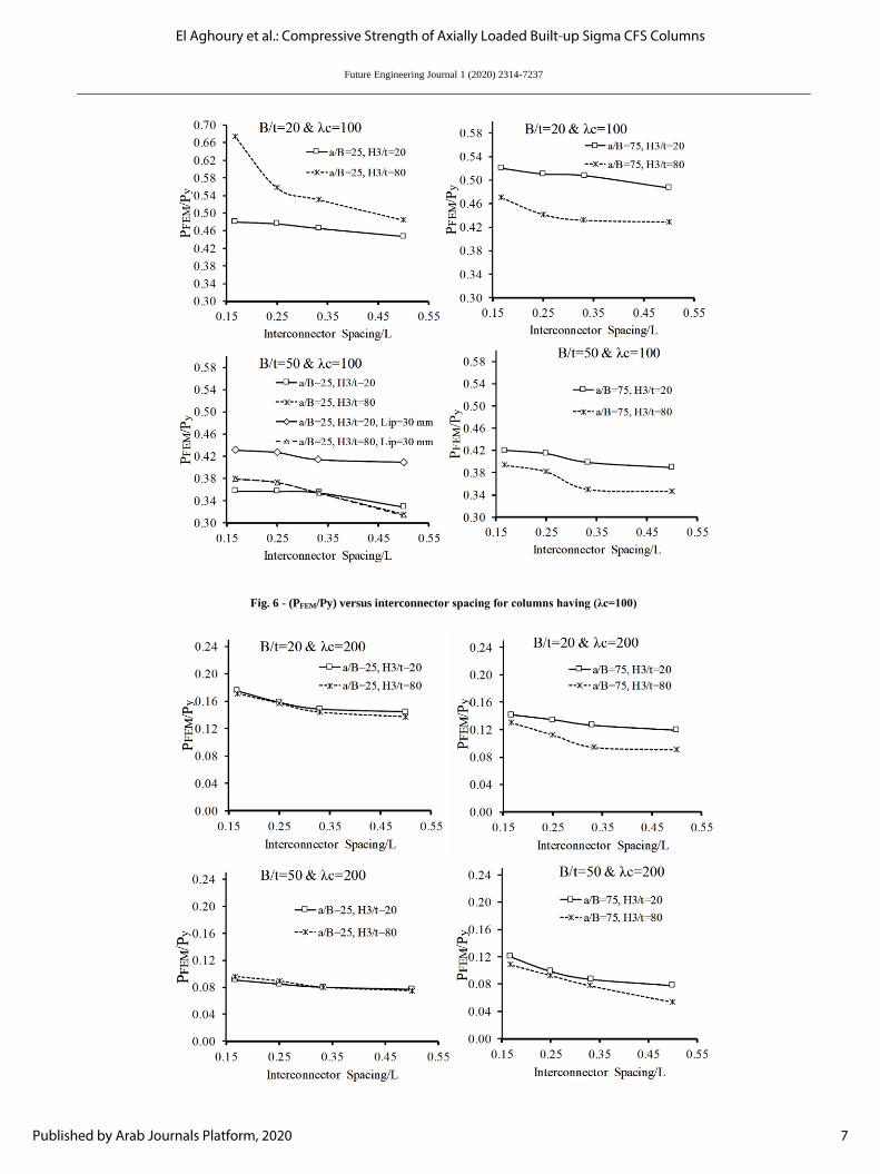
The effect of fastener spacing on the ultimate loads of the combined sections, Pu, was first determined. The normalized ratio, Pu/Py, is plotted in Figs. 6 &
7 as a function connecting fastener spacing.
Close examination of the results reveals that in sections with large interior web width to thickness ratio, H3/t = 80, the ultimate loads decrease as the
spacing between the connecting fasteners increases. For instance, the ratio Pu/Py of columns S-20-25-80-L (L/ry =100) decreased by 30% when the
fastener spacing, S, increased from L/4 to L/2. Similarly, the maximum capacity, Pu/Py, of column sections S-50-25-80-L (L/ry = 100) are 0.44 and 0.37
for connecting fastener spacing equal to L/4 and L/2; respectively. On the other hand, the spacing of the connecting fastener does not greatly influence the
ultimate loads of columns with sections having small web width to thickness ratios, H3/t=20. Columns with sections S-20-25-20-L exhibited ratios Pu/Py
of 0.48 and 0.45 for fastener spacing L/4 and L/2 respectively. Also, El Aghoury M. A., et. al., (2016) showed that the ultimate loads of sections with
interior web width to thickness ratios, H3/t, equal to 40 decreased slightly with the increase of the connecting fastener spacing.
6
Future Engineering Journal, Vol. 1, Iss. 1 [2020], Art. 6
https://digitalcommons.aaru.edu.jo/fej/vol1/iss1/6
Future Engineering Journal 1 (2020) 2314-7237
Fig. 6 - (PFEM/Py) versus interconnector spacing for columns having (λc=100)
7
El Aghoury et al.: Compressive Strength of Axially Loaded Built-up Sigma CFS Columns
Published by Arab Journals Platform, 2020

Future Engineering Journal 1 (2020) 2314-7237
Fig. 7 - (PFEM/Py) versus different interconnector spacing for columns (λc=200)
The failure modes are characterized by interactive overall sectional (local/distortional) buckling, for columns with moderate overall member
slenderness ratios, λc=100. However, sections with large interior web width to thickness ratios, H3/t = 80, experienced clear local buckling waves in the
web in addition to the overall buckling mode. These waves are clearly visible for columns with connecting fastener spacing equal L/4. Moreover, for
sections having higher values of web recess depth to thickness ratio the sectional buckling mode changes from distortional buckling to local buckling if
the spacing of connecting fasteners is decreased. Additionally, the rotational stiffness of the flange web juncture is enhanced when the spacing between
webs connecting fasteners decreases as shown in Figs 8, 9 and 10. Further, in the un-lipped flange sections, additional distortional buckling waves are
formed in the flanges. In sections with low interior web width to thickness ratios, H3/t = 20, failure modes are mainly interactive distortional buckling in
the flanges accompanied by overall member buckling, However, in sections with unlipped flanges having, b/t = 50, some local buckling waves are visible
in the flanges. Additionally, in long columns having, L/ry = 200, the observed failure modes are mainly overall buckling. Failure modes are depicted in
Figs. 8 & 9 for columns with sections having H3/t = 80, while Fig. 11 shows the failure modes of columns having H3/t = 20.
Lipped flange section Unlipped flange sections
L/2 L/4 L/2 L/4
Fig. 8 - Failure modes of sections with b/t = 20, H3/t = 80, L/ry = 100
Lipped flange section Unlipped flange sections
L/2 L/4 L/2 L/4
Fig. 9 - Failure modes of columns sections having b/t = 50, H3/t = 80, L/ry = 100
8
Future Engineering Journal, Vol. 1, Iss. 1 [2020], Art. 6
https://digitalcommons.aaru.edu.jo/fej/vol1/iss1/6

Future Engineering Journal 1 (2020) 2314-7237
L/2 L/4
Fig. 10: Failure modes of columns sections having b/t = 50, H3/t = 20, L/ry = 100
5. Comparison with standard codes
In this section, the ultimate capacities of the compound sigma section columns are determined using the design rules provided in Eurocode-3 (2001),
AISI-2012, and the direct strength method, DSM, (2002). According to Eurocode-3 and AISI-2012, determination of the design loads is based on the
effective width concept, where the ultimate capacities are calculated as the product of the reduced sectional area and the maximum stress, Fn. The latter
will be the lower of the yield stress and the flexural buckling stress which is determined using the full section properties. In the DSM, the axial strength
will be the lowest of the local, distortional, and the overall buckling strengths. This method requires the calculation of the elastic critical local and
distortional buckling stresses. The values of these stresses are determined using CUFSM computer program. Results of this comparison are listed in Table
4, in which the FEM ultimate loads represent the results corresponding to fastener spacing equal to L/4.Moreover, in AISI-2012, the loads are calculated
using the modified slenderness ratio given in Equation (1).
2 2( ) ( ) ( )m yo
i
KL KL S
r r r= + (1)
where (KL/r) yo is the overall slenderness ratio of the member about y-axis,
s is the fastener spacing, and
ri is the radius of gyration of the single element about y-axis
It is interesting to point out that the elastic buckling behavior of the built-up sigma sections is the basis for assessing the capabilities of DSM Schafer
(2002) to predict the ultimate loads of such sections. In the model, the nodal lines that correspond to the connecting fasteners location are constrained.
This modeling assumed that the webs of the two sections are connected along the whole length of the columns. Results are depicted in Figs. 11 and 12 for
wide flange sections (B = 50) with ratios a/B = 0.25 and 0.75; respectively. It is noted that, increasing the ratio a/B increases both the critical local and
distortional buckling loads. Moreover, for the sake of comparison, the results corresponding to single sections are added to the figure.
The comparison reveals that the results of the three design codes are comparable and, in some cases slightly higher than the ultimate loads predicted by the
Finite Element Model, especially for sections with large interior web width to thickness ratios, H3/t =80. This is intuitively explained as a result of the
codes limits for the ratio of interconnector spacing to radius of gyration of an individual shape does not exceed one-half the governing slenderness ratio of
the built-up member as indicated in Equation (2) (AISI-2012, provision, D1.2). Thus, the capacities are calculated assuming full contact between the two
sections.
Table 4 - Comparison with design codes
Specimen KL/ry
Pu/Py 𝑷𝑭𝑬𝑴𝑷𝑬𝑼𝑹𝑶
𝑷𝑭𝑬𝑴𝑷𝑨𝑰𝑺𝑰
𝑷𝑭𝑬𝑴𝑷𝑫𝑺𝑴
FEM Eurocode-3 AISI-2012 DSM
S20-25-20-L 100 0.47 0.48 0.5 0.55 0.98 0.94 0.85
S20-25-80-L 100 0.69 0.49 0.51 0.57 1.4 1.35 1.21
S50-25-20-L 100 0.42 0.48 0.46 0.4 0.87 0.91 1.05
S50-25-80-L 100 0.42 0.46 0.44 0.55 0.91 0.95 0.76
S20-25-20-U 100 0.51 0.49 0.48 0.54 1.02 1.06 0.94
S20-25-80-U 100 0.64 0.48 0.48 0.62 1.33 1.33 1.03
S50-25-20-U 100 0.31 0.44 0.41 0.39 0.7 0.75 0.79
S50-25-80-U 100 0.51 0.44 0.37 0.4 1.11 1.37 1.27
S20-75-80-L 100 0.59 0.48 0.51 0.55 1.22 1.15 1.07
S50-75-20-L 100 0.42 0.47 0.47 0.58 0.89 0.89 0.72
S20-25-20-L 200 0.14 0.17 0.155 0.18 0.82 0.93 0.77
S20-25-80-L 200 0.15 0.16 0.156 0.19 0.94 0.96 0.78
S50-25-20-L 200 0.12 0.16 0.19 0.18 0.75 0.63 0.67
S50-25-80-L 200 0.22 0.16 0.18 0.185 1.37 1.22 1.18
S20-25-20-U 200 0.15 0.16 0.125 0.19 0.93 1.20 0.78
S20-25-80-U 200 0.15 0.17 0.124 0.16 0.88 1.21 0.94
S50-25-20-U 200 0.09 0.157 0.146 0.18 0.57 0.62 0.5
S50-25-80-U 200 0.27 0.157 0.138 0.182 1.72 1.95 1.5
S20-75-80-L 200 0.12 0.16 0.167 0.17 0.71 0.78 0.7
9
El Aghoury et al.: Compressive Strength of Axially Loaded Built-up Sigma CFS Columns
Published by Arab Journals Platform, 2020

Future Engineering Journal 1 (2020) 2314-7237
S50-75-20-L 200 0.12 0.16 0.14 0.189 0.85 0.13 0.63
Mean, Pm 1.00 1.02 0.91
However, the spacing S = L/4 in the studied cases is slightly larger than this limit. The ultimate capacities, Pu/Py, of specimens S50-25-20-L and S50-25-
50-L for different bolt spacing, s, are given in Table 5. It is obvious that the ultimate strength increases with decreasing the bolt spacing, especially for
sections with large web width to thickness ratios, H3/t, and the mode of failure changes as depicted in Fig. 13.
2
i
y
r LS
r (2)
where L = overall member length
ri = radius of gyration of the single section about y-axis
ry = radius of gyration of the whole section about y-axis
Table 5 - Pu/Py for different bolt spacing, s.
Specimen Bolt spacing, s
L/2 L/4 L/6
S50-25-20-L 0.4 0.42 0.42
S50-25-80-L 0.37 0.42 0.63
Fig. 11- elastic buckling loads of column specimen S50-25
Fig. 12: Elastic buckling loads of column specimen S50-75
100
101
102
103
0
1
2
3
4
5
6
Half Wave Length (cm)
Pcr/
Py
Single Section
Double Section
100
101
102
103
0
1
2
3
4
5
6
Half Wave Length (cm)
Pcr/
Py
Single Section
Double Section
10
Future Engineering Journal, Vol. 1, Iss. 1 [2020], Art. 6
https://digitalcommons.aaru.edu.jo/fej/vol1/iss1/6

Future Engineering Journal 1 (2020) 2314-7237
Lipped flange section
L/2 L/4 L/5 L/6
Fig. 13 - failure modes of columns sections having b/t = 50, H3/t = 80, for different fastener spacing, (L/ry = 100)
6. Conclusions
In this paper, the axial compressive strength of columns consist of back to back cold formed sigma sections is investigated experimentally and
numerically. In the tests, it is found that the failure modes of short columns are governed by distortional buckling of the flanges. However, for columns
having intermediate height, the failure mode is the interactive distortional overall buckling. The failure modes predicted by the finite element model are
comparable with the test results. Further, although the ultimate strength of sections with large interior web width to thickness ratios goes down
significantly as the spacing between the connecting fastener increases, strength of sections having small web width to thickness ratios is only slightly
affected by fastener spacing, This is also observed experimentally. In-addition, failure modes of intermediate height columns are interactive overall-
sectional (local/distortional) buckling mode, while in long columns it is mainly overall buckling. Moreover, for sections having higher values of web
recess depth to thickness ratio the sectional buckling mode changes from distortional buckling to local buckling if the spacing of connecting fasteners is
decreased. Additionally, the rotational stiffness of the flange web juncture is enhanced when the spacing between webs connecting fasteners decreases.
This causes higher critical distortional buckling loads compared with that of the single sigma sections. Moreover, comparison with the design codes
reveals that, the predicted ultimate loads of the three codes, Eurocode-3, AISI, and DSM are comparable. In addition, the limit of the spacing between
fasteners that is defined in AISI is necessary to achieve the ultimate capacity of the sections.
REFERENCES
Lau H. H. and Ting T. C. H., (2009). An investigation of the compressive strength of cold-formed steel built-up I-sections. Proceedings of Sixth International
Conference on Advances in Steel Structures, Hong Kong, China.
Klingshirn D. J., Sumner E. A., and Rahman N. A., (2010). Experimental investigation of optimized cold-formed steel compression member. Twentieth
International conference on cold formed steel structures, St. Louse, Missouri, U.S.A., November.
Kang T. H., Biggs K. A.., and Ramseyer C., (2013). Buckling modes of cold-formed steel columns. IACSIT International Journal of Engineering and Technology,
5(4).
Muftah F., Sani1M. S., Muda M. F. and Shahrin M. (2014). Assessment of connection arrangement of built-up cold-formed steel section under axial compression.
Advanced Materials Research, 1043, pp 252-257.
Fratamic D. C., Torabian S., Schafer B. W. (2015 ). Composite action in global buckling of built-up columns using semi-analytical fastener element. Proceedings of
the Annual Stability Conference Structural Stability Research Council Nashville, Tennessee, March.
Craveiro H. D., Rodrigues J. P. C., Laim L. (2016). Buckling resistance of axially loaded cold-formed steel columns. Thin-Walled Structures, 106, pp 358–375.
Lu Y., Zhou T., Li W., Wu H. (2017). Experimental investigation and a novel direct strength method for cold-formed built-up I-section columns. Thin-Walled
Structures, 112, pp 125–139.
Fratamico D. C., Torabian S., Zhao X, Rasmussen K. J.R., Schafer B. W. (2018). Experiments on the global buckling and collapse of built-up cold-formed steel
columns" Journal of Constructional Steel Research 144, pp 65–80.
Fratamico D. C., Torabian S., Zhao X, Rasmussen K. J.R., Schafer B. W. (2018). Experimental study on the composite action in sheathed and bare built-up cold-
formed steel columns. Thin-Walled Structures 127, pp 290–305.
El Aghoury M. A., Hanna M. T. and Amoush E. A. (2104). Effect of initial imperfections on axial strength of cold formed steel single lipped sigma section.
Eurosteel 2014, Naples, Italy, September.
ANSYS, Version 12.0.1, Swanson Analysis Systems, Houston, PA.Desalvo, G. J., and Gorman, R. W.,
El Aghoury M. A., Hanna M. T. and Amoush E. A. (2106). Axial stability of columns composed of combined sigma CFS. Proceedings of the Annual Stability
Conference Structural Stability Research Council Orlando, Florida, April.
Eurocode 3, (2001). Design of steel structures. prEN1993-1-1, final draft, September.
American Iron and Steel Institute, AISI, (2012). Cold-formed steel design manual.
11
El Aghoury et al.: Compressive Strength of Axially Loaded Built-up Sigma CFS Columns
Published by Arab Journals Platform, 2020

Future Engineering Journal 1 (2020) 2314-7237
Schafer B. W.,(2002). Design manual for the direct strength method of cold-formed steel design. Final Report to the American Iron and Steel Institute, Washington,
DC.
CUFSM V3.12, . Elastic Buckling Analysis of Thin-Walled Members by Finite Strip Analysis. http://www.ce.jhu.edu/bschafer/cufsm.
12
Future Engineering Journal, Vol. 1, Iss. 1 [2020], Art. 6
https://digitalcommons.aaru.edu.jo/fej/vol1/iss1/6