compressor slides heinz
DESCRIPTION
ReferenceTRANSCRIPT
Second level Third level
Fourth level Fifth level
Topic Overview---HPB Webinar VIII—December 2012
Process Gas Compressor Failure Avoidance
In this Webinar, the presenter explains some compressor issues and maps out
practical remedies that worked in his 50-year professional experience. Remedial or
preventive actions must be taken by operators, technicians, engineers, and
managers. They are our collective audience and the Webinar will reflect an acute
sense of audience awareness.
In essence, Heinz Bloch will highlight things learned to prevent process
compressor failures. His presentation touches on centrifugal, rotary positive
displacement and reciprocating compressors. It discusses missed opportunities to
get to the bottom of compressor failures and highlights steps taken by leading
performers to operate some machines without shutdown for five, eight, and more
years.
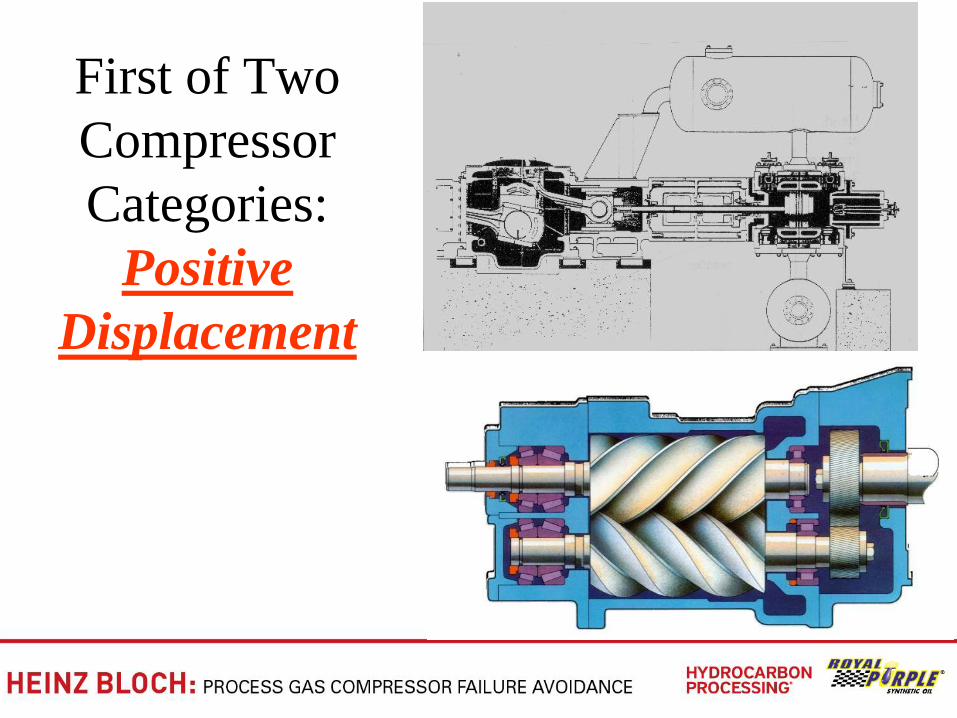
First of Two
Compressor
Categories:
Positive
Displacement
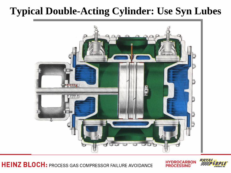
Typical Double-Acting Cylinder: Use Syn Lubes
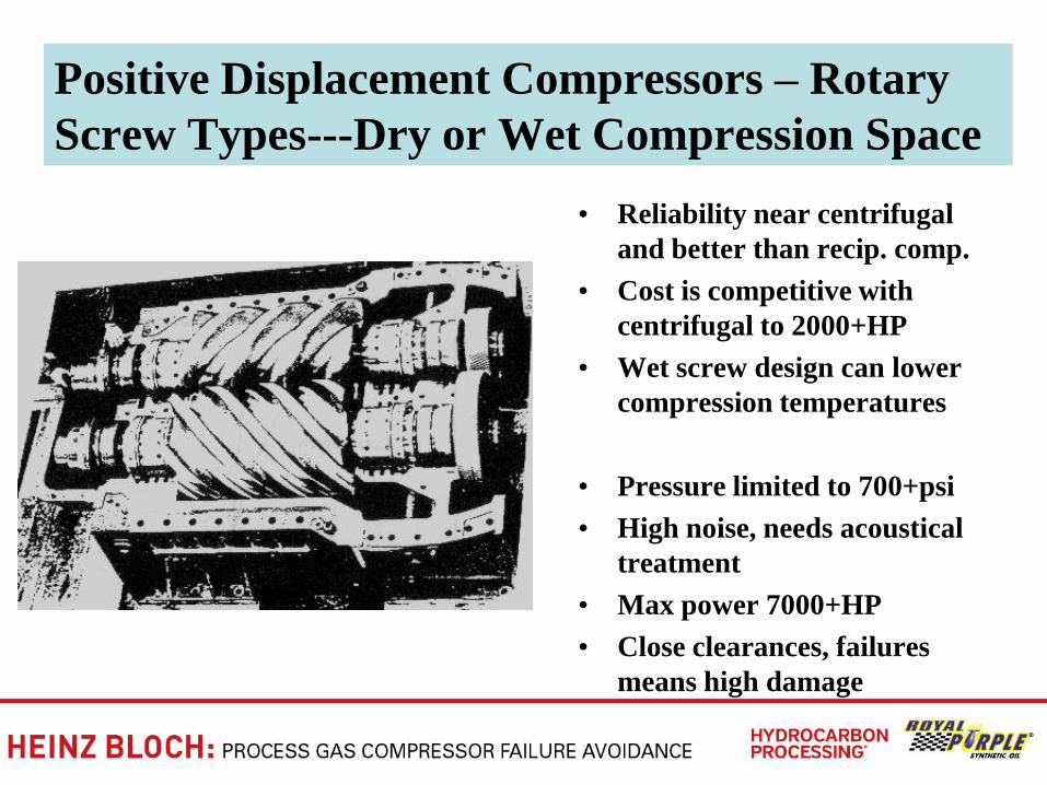
Positive Displacement Compressors – Rotary
Screw Types---Dry or Wet Compression Space
• Reliability near centrifugal
and better than recip. comp.
• Cost is competitive with
centrifugal to 2000+HP
• Wet screw design can lower
compression temperatures
• Pressure limited to 700+psi
• High noise, needs acoustical
treatment
• Max power 7000+HP
• Close clearances, failures
means high damage
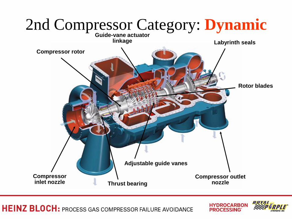
2nd Compressor Category: Dynamic
Compressor outlet nozzle
Rotor blades
Labyrinth seals
Guide-vane actuator linkage
Compressor rotor
Compressor inlet nozzle Thrust bearing
Adjustable guide vanes
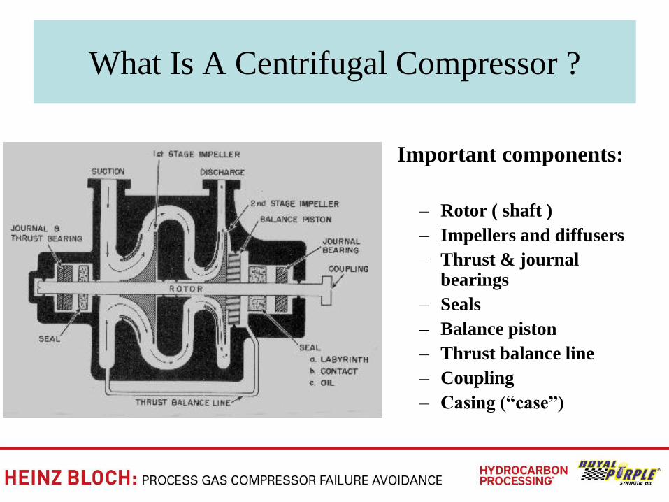
What Is A Centrifugal Compressor ?
Important components:
– Rotor ( shaft )
– Impellers and diffusers
– Thrust & journal bearings
– Seals
– Balance piston
– Thrust balance line
– Coupling
– Casing (―case‖)
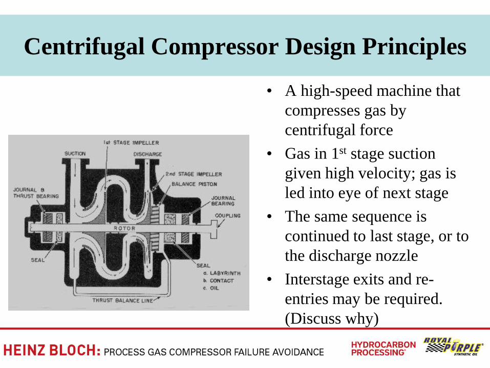
Centrifugal Compressor Design Principles
• A high-speed machine that
compresses gas by
centrifugal force
• Gas in 1st stage suction
given high velocity; gas is
led into eye of next stage
• The same sequence is
continued to last stage, or to
the discharge nozzle
• Interstage exits and re-
entries may be required.
(Discuss why)
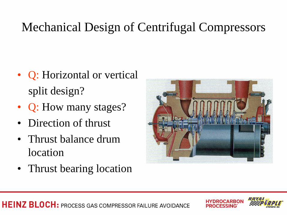
Mechanical Design of Centrifugal Compressors
• Q: Horizontal or vertical
split design?
• Q: How many stages?
• Direction of thrust
• Thrust balance drum
location
• Thrust bearing location
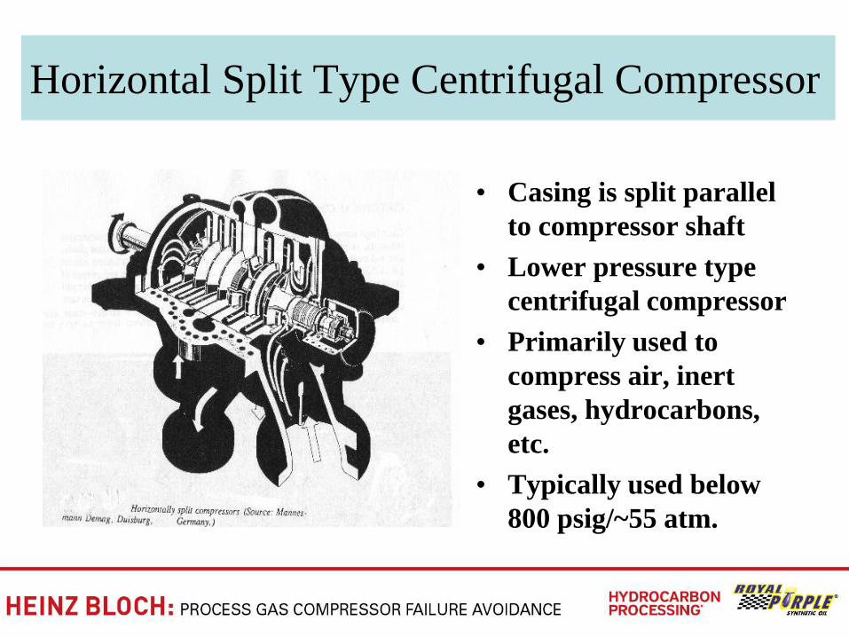
Horizontal Split Type Centrifugal Compressor
• Casing is split parallel
to compressor shaft
• Lower pressure type
centrifugal compressor
• Primarily used to
compress air, inert
gases, hydrocarbons,
etc.
• Typically used below
800 psig/~55 atm.
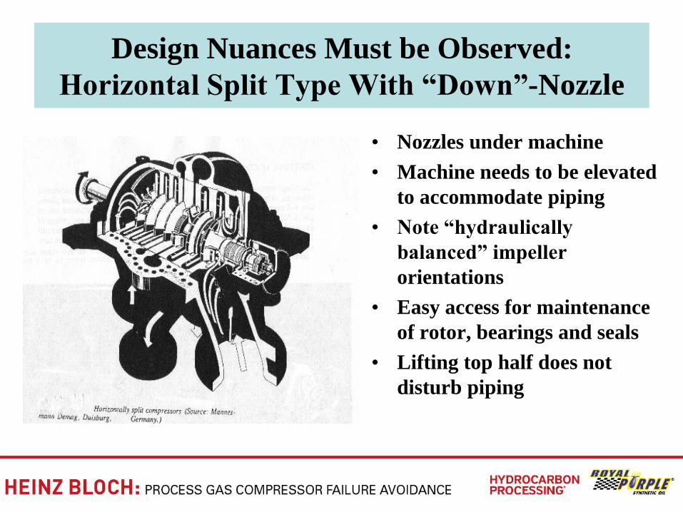
Design Nuances Must be Observed:
Horizontal Split Type With ―Down‖-Nozzle
• Nozzles under machine
• Machine needs to be elevated
to accommodate piping
• Note ―hydraulically
balanced‖ impeller
orientations
• Easy access for maintenance
of rotor, bearings and seals
• Lifting top half does not
disturb piping
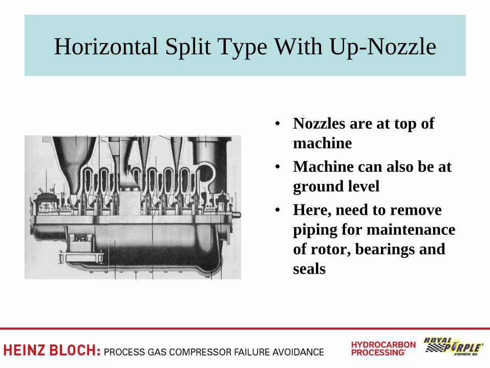
Horizontal Split Type With Up-Nozzle
• Nozzles are at top of
machine
• Machine can also be at
ground level
• Here, need to remove
piping for maintenance
of rotor, bearings and
seals
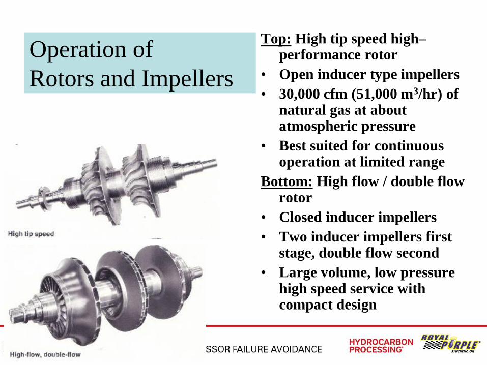
Operation of
Rotors and Impellers
Top: High tip speed high–performance rotor
• Open inducer type impellers
• 30,000 cfm (51,000 m3/hr) of natural gas at about atmospheric pressure
• Best suited for continuous operation at limited range
Bottom: High flow / double flow rotor
• Closed inducer impellers
• Two inducer impellers first stage, double flow second
• Large volume, low pressure high speed service with compact design
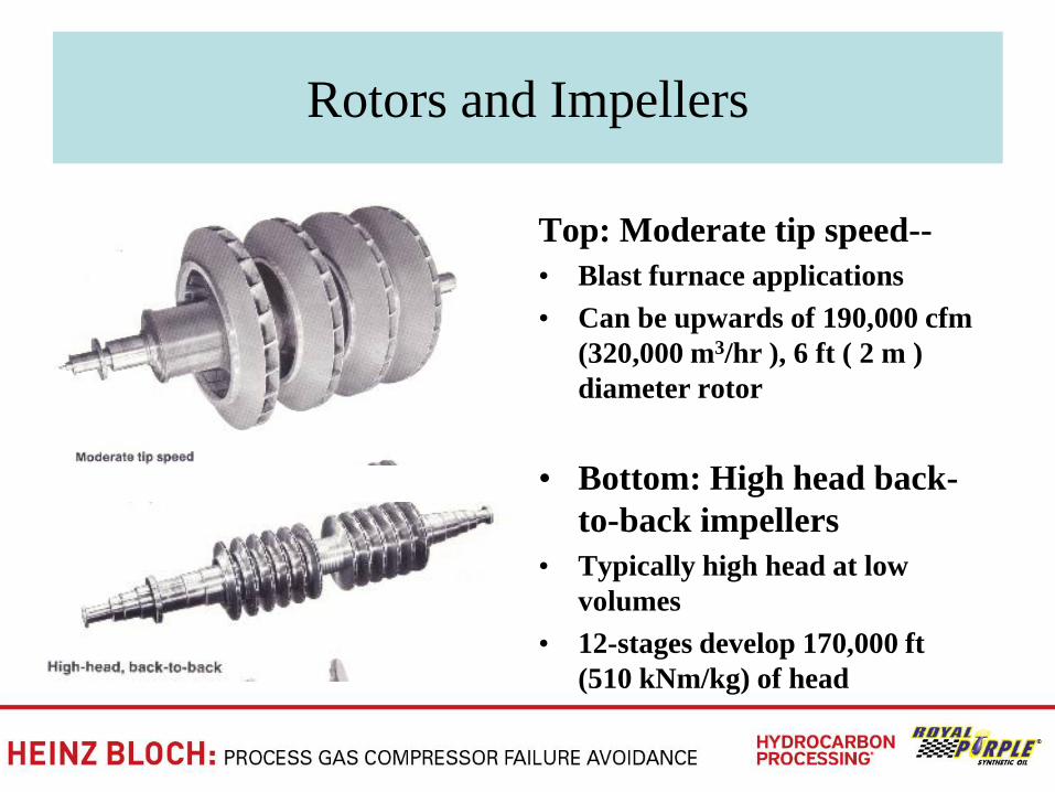
Rotors and Impellers
Top: Moderate tip speed--
• Blast furnace applications
• Can be upwards of 190,000 cfm
(320,000 m3/hr ), 6 ft ( 2 m )
diameter rotor
• Bottom: High head back-
to-back impellers
• Typically high head at low
volumes
• 12-stages develop 170,000 ft
(510 kNm/kg) of head
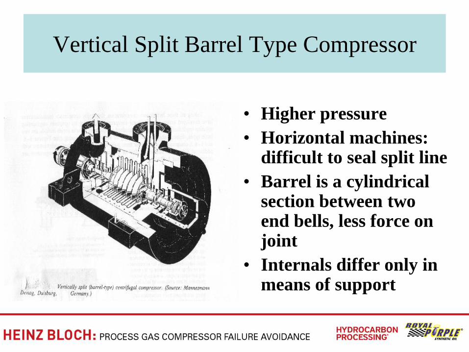
Vertical Split Barrel Type Compressor
• Higher pressure
• Horizontal machines: difficult to seal split line
• Barrel is a cylindrical section between two end bells, less force on joint
• Internals differ only in means of support
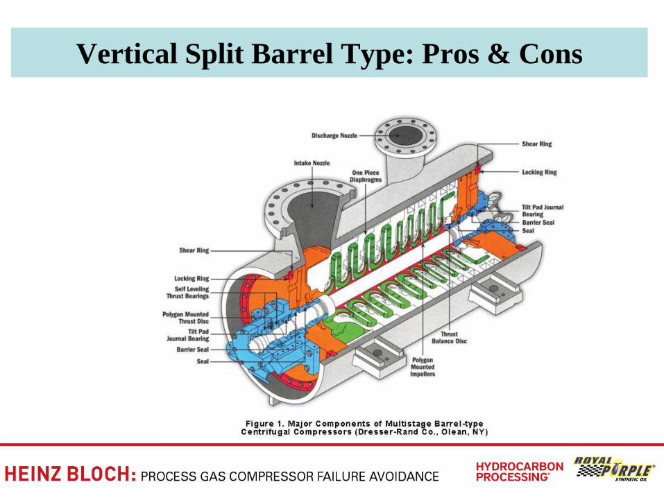
Vertical Split Barrel Type: Pros & Cons
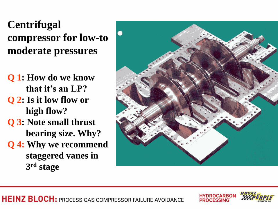
Centrifugal
compressor for low-to
moderate pressures
Q 1: How do we know
that it’s an LP?
Q 2: Is it low flow or
high flow?
Q 3: Note small thrust
bearing size. Why?
Q 4: Why we recommend
staggered vanes in
3rd stage
Lubes for Positive Displacement
Compressors Merit Special Attention
• Synthesized hydrocarbons (―synthetics‖) with appropriate additives used in rotary’s compression space and in reciprocating compressor cylinders
• Working with highly qualified lube manufacturers/ formulators is very much recommended
• Qualified manufactures/formulators have application engineers that can explain benefit-to-cost ratios and user experience background
• Turbine oils (high grade mineral oils) in dynamic compressors---our second category
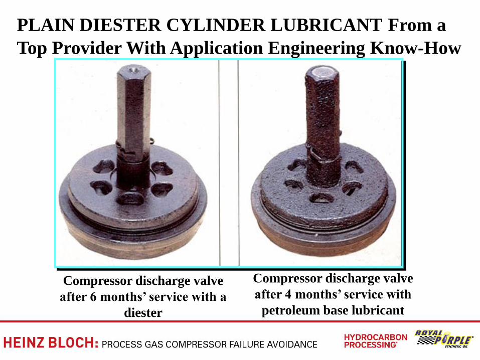
Compressor discharge valve
after 6 months’ service with a
diester
Compressor discharge valve
after 4 months’ service with
petroleum base lubricant
PLAIN DIESTER CYLINDER LUBRICANT From a
Top Provider With Application Engineering Know-How
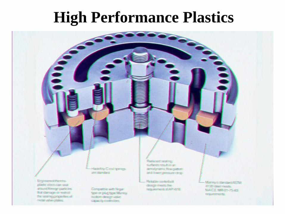
High Performance Plastics
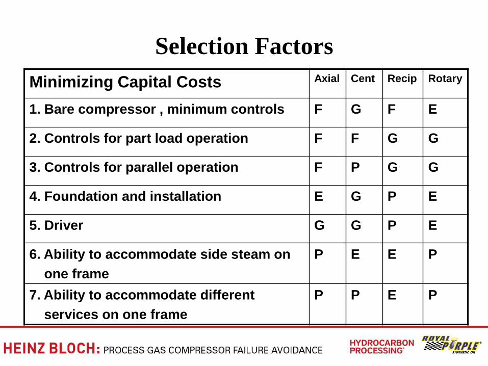
Selection Factors
Minimizing Capital Costs Axial Cent Recip Rotary
1. Bare compressor , minimum controls F G F E
2. Controls for part load operation F F G G
3. Controls for parallel operation F P G G
4. Foundation and installation E G P E
5. Driver G G P E
6. Ability to accommodate side steam on
one frame
P E E P
7. Ability to accommodate different
services on one frame
P P E P
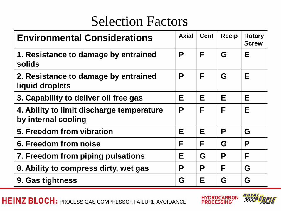
Selection Factors Environmental Considerations Axial Cent Recip Rotary
Screw
1. Resistance to damage by entrained
solids
P F G E
2. Resistance to damage by entrained
liquid droplets
P F G E
3. Capability to deliver oil free gas E E E E
4. Ability to limit discharge temperature
by internal cooling
P F F E
5. Freedom from vibration E E P G
6. Freedom from noise F F G P
7. Freedom from piping pulsations E G P F
8. Ability to compress dirty, wet gas P P F G
9. Gas tightness G E G G
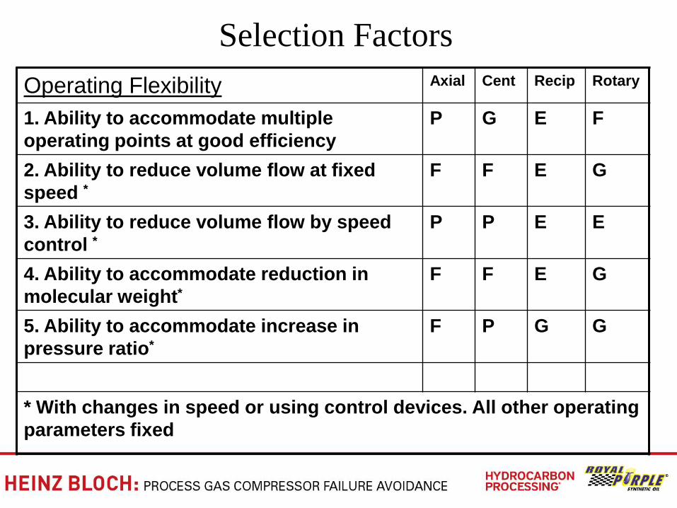
Selection Factors
Operating Flexibility Axial Cent Recip Rotary
1. Ability to accommodate multiple
operating points at good efficiency
P G E F
2. Ability to reduce volume flow at fixed
speed *
F F E G
3. Ability to reduce volume flow by speed
control *
P P E E
4. Ability to accommodate reduction in
molecular weight*
F F E G
5. Ability to accommodate increase in
pressure ratio*
F P G G
* With changes in speed or using control devices. All other operating
parameters fixed
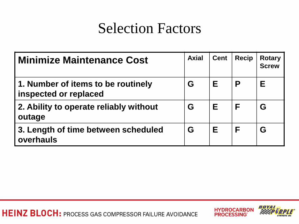
Selection Factors
Minimize Maintenance Cost Axial Cent Recip Rotary
Screw
1. Number of items to be routinely
inspected or replaced
G E P E
2. Ability to operate reliably without
outage
G E F G
3. Length of time between scheduled
overhauls
G E F G
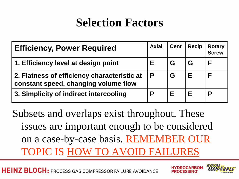
Selection Factors
Efficiency, Power Required Axial Cent Recip Rotary
Screw
1. Efficiency level at design point E G G F
2. Flatness of efficiency characteristic at
constant speed, changing volume flow
P G E F
3. Simplicity of indirect intercooling P E E P
Subsets and overlaps exist throughout. These
issues are important enough to be considered
on a case-by-case basis. REMEMBER OUR
TOPIC IS HOW TO AVOID FAILURES
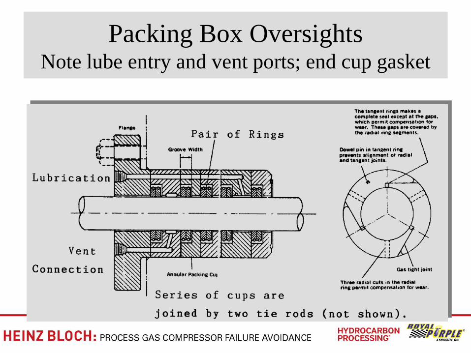
Packing Box Oversights Note lube entry and vent ports; end cup gasket
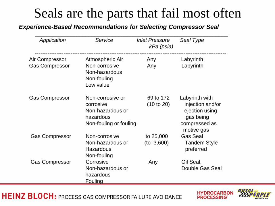
Seals are the parts that fail most often
Experience-Based Recommendations for Selecting Compressor Seal _________________________________________________________________
Application Service Inlet Pressure Seal Type
kPa (psia)
------------------------------------------------------------------------------------------------------------
Air Compressor Atmospheric Air Any Labyrinth
Gas Compressor Non-corrosive Any Labyrinth
Non-hazardous
Non-fouling
Low value
Gas Compressor Non-corrosive or 69 to 172 Labyrinth with
corrosive (10 to 20) injection and/or
Non-hazardous or ejection using
hazardous gas being
Non-fouling or fouling compressed as
motive gas
Gas Compressor Non-corrosive to 25,000 Gas Seal
Non-hazardous or (to 3,600) Tandem Style
Hazardous preferred
Non-fouling
Gas Compressor Corrosive Any Oil Seal,
Non-hazardous or Double Gas Seal
hazardous
Fouling
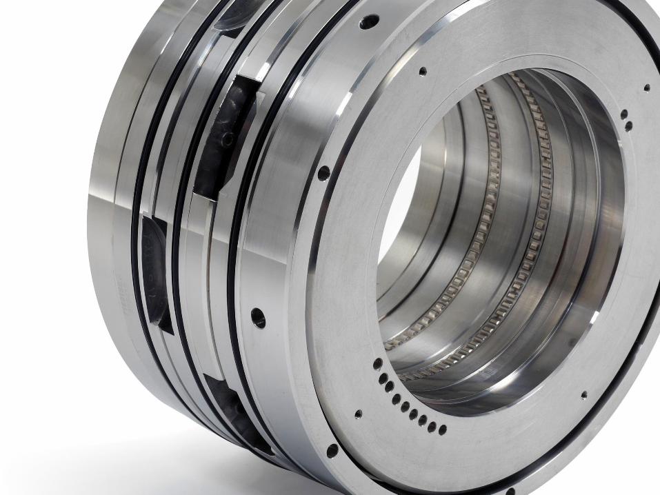
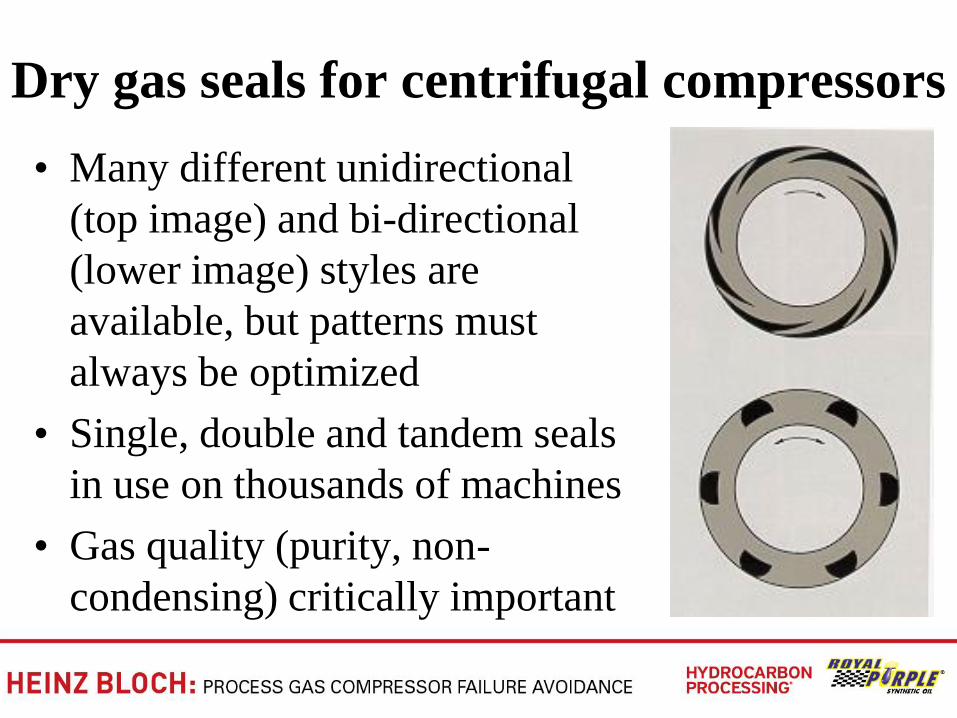
Dry gas seals for centrifugal compressors
• Many different unidirectional
(top image) and bi-directional
(lower image) styles are
available, but patterns must
always be optimized
• Single, double and tandem seals
in use on thousands of machines
• Gas quality (purity, non-
condensing) critically important
Why assigning total responsibility to one
commercial entity is critically important
• Compressor manufacturer
• Original DGS (―dry gas seal‖) manufacturer
• Support system designer
• Support system manufacturer (fabricator)
• On existing compressors, dry gas seal options
include a UK manufacturer capable of fully
rebuilding/testing (or supplying its own) DGS
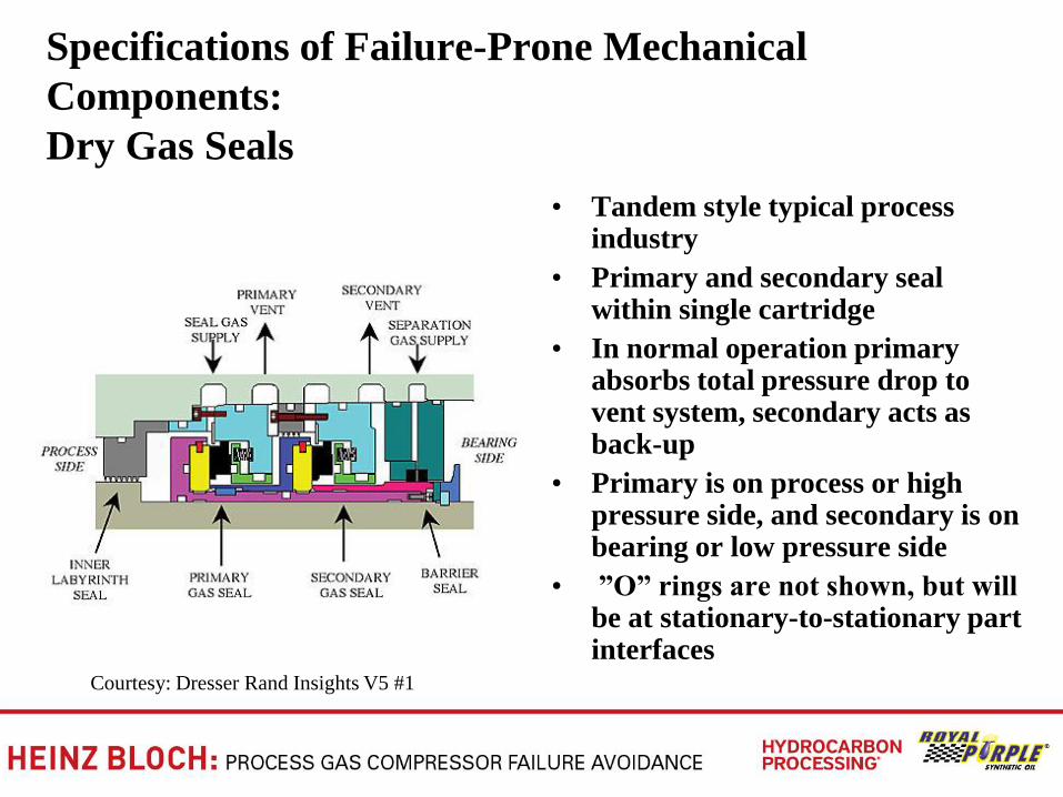
Specifications of Failure-Prone Mechanical
Components:
Dry Gas Seals
• Tandem style typical process industry
• Primary and secondary seal within single cartridge
• In normal operation primary absorbs total pressure drop to vent system, secondary acts as back-up
• Primary is on process or high pressure side, and secondary is on bearing or low pressure side
• ‖O‖ rings are not shown, but will be at stationary-to-stationary part interfaces
Courtesy: Dresser Rand Insights V5 #1
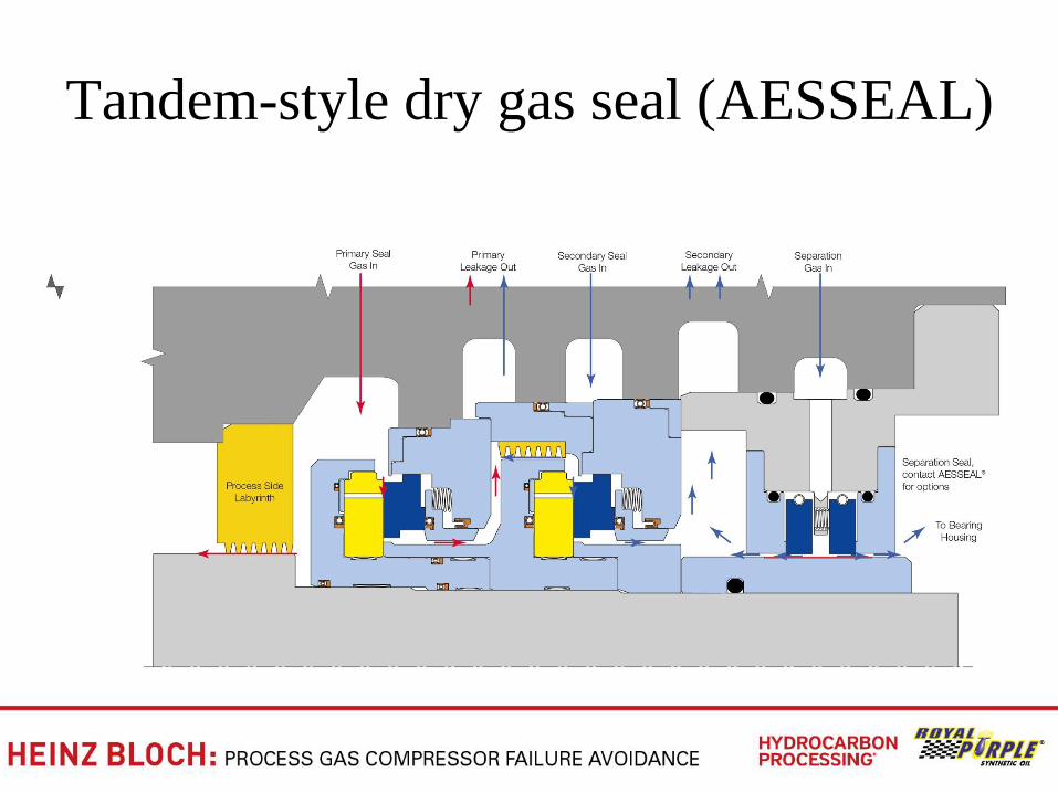
Tandem-style dry gas seal (AESSEAL)
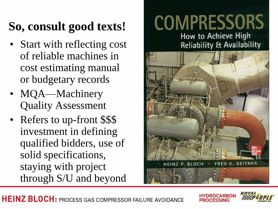
So, consult good texts!
• Start with reflecting cost of reliable machines in cost estimating manual or budgetary records
• MQA—Machinery Quality Assessment
• Refers to up-front $$$ investment in defining qualified bidders, use of solid specifications, staying with project through S/U and beyond