compsci514: computer networks lecture 17: datacenter
TRANSCRIPT

CompSci 514: Computer NetworksLecture 17: Datacenter Network
Architectures Xiaowei Yang

Overview
• Motivation
• Challenges
• The FatTree architecture

�����������
�� ���������$ ������������� � ��������
,� ���"����� �%���������#���� ������� ����� �����
,� �������!���������������#������ ��$���
�� � � ��������������� �*�� �����������+�
,� ��� �������� ��%����� � ��� �� �%��������������#��������%����&�
�� � ��!�����������������������������
,� *�����+�����������
,� ��� ���'�����������������������
,� � �������� ���� �����

Two design choices
• Specialized hardware and communication protocols– InfiniBand, Myrinet– Cons: expensive, may not support TCP/IP
• Commodity Ethernet switches and routes– Aggregate cluster bandwidth scales poorly with
cluster size– High bandwidth incurs non-linear cost

��������������������� � � ���
�� � ��������������������'������������$��%��������
�� �����������������������'&���� ��������$���%����������
�� �������������!�����������������'&����������������
#� ��������������������(")!'����*!'�������������� �������
�� �������������������������������������'&���������� ���
� ���
� ��
� ��
���������������!����������� ����� �������� ������� ��������

�������������������������
�� ������������� ��� ���
���
���
����
����
����
����
����
�� ����� ������ ������ ������ ������
�����������
� ������
������
���!����
��!����
��!����
�������������!�����

FatTree Design Goals• Scalable interconnection bandwidth: it should be possible for an
arbitrary host in the data center to communicate with any other host in the network at the full bandwidth of its local network interface.
• Economies of scale: just as commodity personal computers became the basis for large-scale computing environments, we hope to leverage the same economies of scale to make cheap off-the-shelf Ethernet switches the basis for large- scale data center networks.
• Backward compatibility: the entire system should be back- ward compatible with hosts running Ethernet and IP. That is, existing data centers, which almost universally leverage com- modity Ethernet and run IP, should be able to take advantage of the new interconnect architecture with no modifications.

Components
• GigE switches
Core
Aggregation
Edge
Figure 1: Common data center interconnect topology. Host to switch links are GigE and links between switches are 10 GigE.
0
5
10
15
20
25
30
35
40
1000 10000
Estim
ated
cos
t (U
SD m
illio
ns)
Number of hosts
1:13:17:1
Fat-tree
Figure 2: Current cost estimate vs. maximum possible numberof hosts for different oversubscription ratios.
We also include the cost to deliver an oversubscription of 1:1 usingour proposed fat-tree architecture for comparison.
Overall, we find that existing techniques for delivering high lev-els of bandwidth in large clusters incur significant cost and thatfat-tree based cluster interconnects hold significant promise for de-livering scalable bandwidth at moderate cost. However, in somesense, Figure 2 understates the difficulty and expense of employingthe highest-end components in building data center architectures.In 2008, 10 GigE switches are on the verge of becoming commod-ity parts; there is roughly a factor of 5 differential in price per portper bit/sec when comparing GigE to 10 GigE switches, and thisdifferential continues to shrink. To explore the historical trend,we show in Table 1 the cost of the largest cluster configurationthat could be supported using the highest-end switches availablein a particular year. We based these values on a historical study ofproduct announcements from various vendors of high-end 10 GigEswitches in 2002, 2004, 2006, and 2008.
We use our findings to build the largest cluster configuration thattechnology in that year could support while maintaining an over-subscription of 1:1. Table 1 shows the largest 10 GigE switch avail-able in a particular year; we employ these switches in the core andaggregation layers for the hierarchical design. Tables 1 also showsthe largest commodity GigE switch available in that year; we em-
Hierarchical design Fat-tree
Year 10 GigE Hosts Cost/ GigE Hosts Cost/GigE GigE
2002 28-port 4,480 $25.3K 28-port 5,488 $4.5K2004 32-port 7,680 $4.4K 48-port 27,648 $1.6K2006 64-port 10,240 $2.1K 48-port 27,648 $1.2K2008 128-port 20,480 $1.8K 48-port 27,648 $0.3K
Table 1: The maximum possible cluster size with an oversub-scription ratio of 1:1 for different years.
ploy these switches at all layers of the fat-tree and at the edge layerfor the hierarchical design.
The maximum cluster size supported by traditional techniquesemploying high-end switches has been limited by available portdensity until recently. Further, the high-end switches incurred pro-hibitive costs when 10 GigE switches were initially available. Notethat we are being somewhat generous with our calculations for tra-ditional hierarchies since commodity GigE switches at the aggre-gation layer did not have the necessary 10 GigE uplinks until quiterecently. Clusters based on fat-tree topologies on the other handscale well, with the total cost dropping more rapidly and earlier (asa result of following commodity pricing trends earlier). Also, thereis no requirement for higher-speed uplinks in the fat-tree topology.
Finally, it is interesting to note that, today, it is technically in-feasible to build a 27,648-node cluster with 10 Gbps bandwidthpotentially available among all nodes. On the other hand, a fat-tree switch architecture would leverage near-commodity 48-port 10GigE switches and incur a cost of over $690 million. While likelycost-prohibitive in most settings, the bottom line is that it is noteven possible to build such a configuration using traditional aggre-gation with high-end switches because today there is no product oreven Ethernet standard for switches faster than 10 GigE.
2.2 Clos Networks/Fat-TreesToday, the price differential between commodity and non-
commodity switches provides a strong incentive to build large-scalecommunication networks from many small commodity switchesrather than fewer larger and more expensive ones. More than fiftyyears ago, similar trends in telephone switches led Charles Clos todesign a network topology that delivers high levels of bandwidthfor many end devices by appropriately interconnecting smallercommodity switches [11].
65

����������������� ������� �������� � ����
������������������������
��� �
�� �������������������� ������������

����������������� ������� �������� � ����
������������������������
��� �
�� �������������������������������������
•� �������������������������
•� �� ��������������������������� �����������������

����������������� ������� �������� � ����
������������������������
��� �
�� �������������������� ������ ���������������
•� ������������������������
•� �����������������������������

����������������� ������� �������� � ����
������������������������
��� �
�� ���2����������������������������3��������
•� � �������������������� ��������� ��� ����������
�� �����������������������������������������������

����������������� ������� �������� � ����
������������������������
��� �
�� ��� ����������������� ���������������������������� ��
�� ������������������������������������������ ���� ������������������ ���� ��� ����������

����������
�� �������
(� ��� �����������!� !����������������������������������!�
���� !��������� �����������������������
���������������&�� � �!'���� �����������������
(� ������"������ �������������������������� ��������� ��������������������������������������������!�
�� ������������������������
(� ������������2����� �����������+�3����� �������� �������������������������
�3����� ������������������� �����)������!������������*�
�� �������������������#�

�� �����������
�� �������������"� ��%������������������������������������%�������! �����������������% ����������
�� ���������%����� ����� �����#�
&$� ��%��������������������
'$� ����������� ������
($� ������������ ���������
�� �� ���� ����������������������������

Addressing• Switches are given addresses 10.pod.switch.1– Pod in [0,k-1]– Switches in [0,k-1]
• Core switches: 10.k.j.i– j,I are coordinates in the core switch grid, each in
[1,k/2]
• Hosts: 10.pod.switch.ID– Id in [2, k/2+1]

���������������
�� �� #��� ����%� � ������ ����������!�� �������"���� �� ���
&� ���������������� ���� ���������������� ����%�������
�� �� ����� !������������������ ����������������� �
&� �����%� � ���� ���� ��� !� �������� ��%��� �������
&� � ����%� � ���� ���� ������������������%��� �������

�������������������������� ���
��������� ���������
��� � �������
����������
��� � �������
���������� ��
���������� ��

�������������������������� ���
��������� ���������
��� � �������
������������ ��
������������ ��
����������
��� � �������
��������� ��
��������� ��

�������������������������� ���
��������� ���������
��� � �������
������������ ��
������������ ��
������������ ��
������������ ��

�������������������������� ���
��������� ���������
��� � �������
������������ ��
������������� ��
����������
��� � �������
��������� ��
��������� ��

������� ����������������������
��������� ���������
�� �� ���������������� ��� ��������
�� ����������������� ����������� ��������
�� ����������� ������� �������������������������

Flow Classification
• Recognize subsequent packets of the same flow, and forward them on the same outgoing port. – Avoid reordering
• Periodically reassign a minimal number of flow output ports to minimize any disparity between the aggregate flow capacity of different ports.

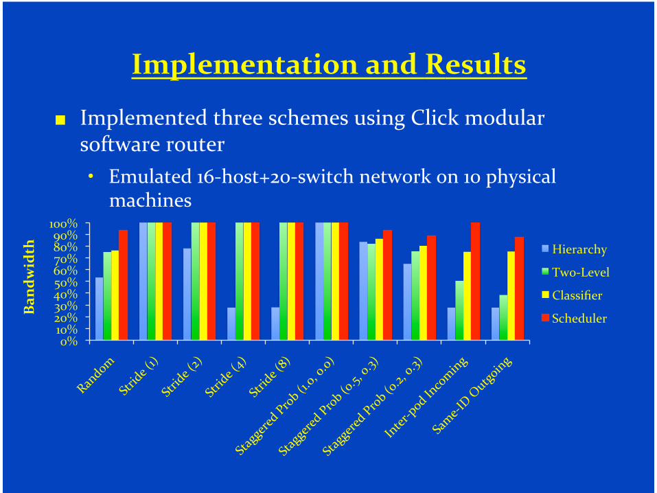
Flow Scheduling• Edge switches locally assign a new flow to the
least- loaded port initially
• Edge switches additionally detect elephant flows and periodically send notifications to a central scheduler
• A central scheduler, possibly replicated, tracks all active large flows and tries to assign them non-conflicting paths if possible.
���������� �������������
�� ��������������������������������������������� ������������
� ��������"'�����.#!������������������"!����������������
��������
�
!-�"!-�#!-�$!-�%!-�&!-�'!-�(!-�)!-�*!-�"!!-�
��������
����������
���������
���������

����������
�� ������������������ ��������������� ��������������
"� ��������������������� ������������
"� �������)%������������&(��������
�� ��������������������������������������������������
"� �� ������������ ����� ����������������
"� ���������� �� ����������������������������
"� ���������%!'�������������
�� �������������
"� ����������� ������������������#%$$��������������

����� �������
����� �������
�������� ������
������������� ����
�������� ��������� � �������� �
�������� � �������� � �������� �
�������� �
�������� �
�������� �
�������� �
�������� �
�������� �
������������������������
���������
�������
Figure 8: Proposed packaging solution. The only external ca-bles are between the pods and the core nodes.
We present our approach in the context of a maximum-capacity27,648-node cluster leveraging 48-port Ethernet switches as thebuilding block of the fat-tree. This design generalizes to clustersof different sizes. We begin with the design of individual pods thatmake up the replication unit for the larger cluster, see Figure 8.Each pod consists of 576 machines and 48 individual 48-port GigEswitches. For simplicity, we assume each end host takes up onerack unit (1RU) and that individual racks can accommodate 48 ma-chines. Thus, each pod consists of 12 racks with 48 machines each.
We place the 48 switches that make up the first two layers of thefat-tree in each pod in a centralized rack. However, we assume theability to package the 48 switches into a single monolithic unit with1,152 user-facing ports. We call this the pod switch. Of these ports,576 connect directly to the machines in the pod, corresponding toconnectivity at the edge. Another 576 ports fan out to one port oneach of the 576 switches that make up the core layer in the fat-tree. Note that the 48 switches packaged in this manner actuallyhave 2,304 total ports (48 ∗ 48). The other 1,152 ports are wiredinternally in the pod switch to account for the required interconnectbetween the edge and aggregation layers of the pod (see Figure 3).
We further spread the 576 required core switches that form thetop of the fat-tree across the individual pods. Assuming a total of48 pods, each will house 12 of the required core switches. Of the576 cables fanning out from each pod switch to the core, 12 willconnect directly to core switches placed nearby in the same pod.The remaining cables would fan out, in sets of 12, to core switcheshoused in remote pods. Note that the fact that cables move in setsof 12 from pod to pod and in sets of 48 from racks to pod switchesopens additional opportunities for appropriate “cable packaging” toreduce wiring complexity.
Finally, minimizing total cable length is another important con-sideration. To do so, we place racks around the pod switch in twodimensions, as shown in Figure 8 (we do not consider three di-mensional data center layouts). Doing so will reduce cable lengthsrelative to more “horizontal” layouts of individual racks in a pod.Similarly, we lay pods out in a 7 × 7 grid (with one missing spot)
to accommodate all 48 pods. Once again, this grid layout will re-duce inter-pod cabling distance to appropriate core switches andwill support some standardization of cable lengths and packagingto support inter-pod connectivity.
We also considered an alternate design that did not collect theswitches into a central rack. In this approach, two 48-port switcheswould be distributed to each rack. Hosts would interconnect to theswitches in sets of 24. This approach has the advantage of requiringmuch shorter cables to connect hosts to their first hop switch andfor eliminating these cables all together if the racks were appro-priately internally packaged. We discarded this approach becausewe would lose the opportunity to eliminate the 576 cables withineach pod that interconnect the edge and aggregation layers. Thesecables would need to crisscross the 12 racks in each pod, addingsignificant complexity.
7. RELATED WORKOur work in data center network architecture necessarily builds
upon work in a number of related areas. Perhaps most closelyrelated to our efforts are various efforts in building scalable inter-connects, largely coming out of the supercomputer and massivelyparallel processing (MPP) communities. Many MPP interconnectshave been organized as fat-trees, including systems from ThinkingMachines [31, 22] and SGI [33]. Thinking Machines employedpseudo-random forwarding decisions to perform load balancingamong fat-tree links. While this approach achieves good load bal-ancing, it is prone to packet reordering. Myrinet switches [6] alsoemploy fat-tree topologies and have been popular for cluster-basedsupercomputers. Myrinet employs source routing based on prede-termined topology knowledge, enabling cut-through low latencyswitch implementations. Hosts are also responsible for load bal-ancing among available routes by measuring round-trip latencies.Relative to all of these efforts, we focus on leveraging commod-ity Ethernet switches to interconnect large-scale clusters, showingtechniques for appropriate routing and packaging.
InfiniBand [2] is a popular interconnect for high-performancecomputing environments and is currently migrating to data centerenvironments. InfiniBand also achieves scalable bandwidth usingvariants of Clos topologies. For instance, Sun recently announceda 3,456-port InfiniBand switch built from 720 24-port InfiniBandswitches arranged in a 5-stage fat-tree [4]. However, InfiniBandimposes its own layer 1-4 protocols, making Ethernet/IP/TCP moreattractive in certain settings especially as the price of 10Gbps Eth-ernet continues to drop.
Another popular MPP interconnect topology is a Torus, for in-stance in the BlueGene/L [5] and the Cray XT3 [32]. A torus di-rectly interconnects a processor to some number of its neighborsin a k-dimensional lattice. The number of dimensions determinesthe expected number of hops between source and destination. In anMPP environment, a torus has the benefit of not having any dedi-cated switching elements along with electrically simpler point-to-point links. In a cluster environment, the wiring complexity of atorus quickly becomes prohibitive and offloading all routing andforwarding functions to commodity hosts/operating systems is typ-ically impractical.
Our proposed forwarding techniques are related to existingrouting techniques such as OSPF2 and Equal-Cost Multipath(ECMP) [25, 30, 19]. Our proposal for multi-path leveragesparticular properties of a fat-tree topology to achieve good per-formance. Relative to our work, ECMP proposes three classes ofstateless forwarding algorithms: (i) Round-robin and randomiza-tion; (ii) Region splitting where a particular prefix is split into twowith a larger mask length; and (iii) A hashing technique that splits
73

���������������� ���
�� ��������������������� ��� ������������������������������������� ������
�� ��������������������
��
���
���
���
���
���
���
��
!��
��
��
��
��
!�
���
���
���
�����������
��������
� ��������������
�����������������

��������� ���������������
�� ������� ��������������������������������������������������� �����
�� ��������� �����������������
0
500
1000
1500
2000
2500
3000
0
100
200
300
400
500
600
700
800
Hierarchical design Fat-tree
Tota
l Hea
t Dis
sipa
tion
(kB
TU/h
r)
Tota
l Pow
er (k
W)
Total power (kW)
Total heat dissipation (kBTU/hr)

�����������
�� ������������������������������
$� ������ ��������������������
$� ��������
$� ����� #����
$� ��������������
�� ��"���������������� ����������������������������
$� ������� ������������������������������� ������������������ ��������������������
$� ��"����������������&("����������������������%'��������
$� ��� ������������������!�����������!������ �

Comments
• Each pod switch connects to only half of the cores– May be hard to wire
• A pod is not loop free– A pod is usually the boundary of l2 and l3. Within
a pod, run l2 and use agg as the default gateway for that pod. Beyond a pod, run l3.
– Must run spanning tree inside a pod