comptec composite pressure tanks · 2019-08-02 · 2 comptec pressure tanks threaded series...
TRANSCRIPT
FILTRATION & PROCESS
COMPOSITE PRESSURE TANKS
COMPTEC®

COMPOS I T E W ATER S Y STEM PRESSURE TANKS 1
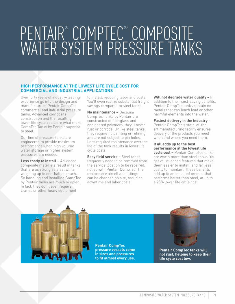
Pentair CompTec pressure vessels come in sizes and pressures to fit almost every use.
Pentair CompTec tanks will not rust, helping to keep their life cycle cost low.
PENTAIR® COMPTEC® COMPOSITE WATER SYSTEM PRESSURE TANKS
HIGH PERFORMANCE AT THE LOWEST LIFE CYCLE COST FOR COMMERCIAL AND INDUSTRIAL APPLICATIONSOver forty years of industry-leading experience go into the design and manufacture of Pentair CompTec commercial and industrial pressure tanks. Advanced composite construction and the resulting lower life cycle costs are what make CompTec Tanks by Pentair superior to steel.Our line of pressure tanks are engineered to provide maximum performance when high volume water storage or higher system pressures are needed.Less costly to install – Advanced composite materials result in tanks that are as strong as steel while weighing up to one-half as much. So handling and installing CompTec by Pentair tanks are much simpler. In fact, they don’t even require cranes or other heavy equipment
to install, reducing labor and costs. You’ll even realize substantial freight savings compared to steel tanks.No maintenance – Because CompTec Tanks by Pentair are constructed of fiberglass and engineered polymers, they’ll never rust or corrode. Unlike steel tanks, they require no painting or relining, and are not subject to pin holes. Less required maintenance over the life of the tank results in lower life cycle costs.Easy field service – Steel tanks frequently need to be removed from the service location to be repaired; not so with Pentair CompTec. The replaceable aircell and fittings can be changed on site, reducing downtime and labor costs.
Will not degrade water quality – In addition to their cost-saving benefits, Pentair CompTec tanks contain no metals that can leach lead or other harmful elements into the water.Fastest delivery in the industry – Pentair CompTec’s state-of-the-art manufacturing facility ensures delivery of the products you need when and where you need them.It all adds up to the best performance at the lowest life cycle cost – Pentair CompTec tanks are worth more than steel tanks. You get value-added features that make them easier to install, and far less costly to maintain. These benefits add up to an installed product that performs better than steel, at up to a 25% lower life cycle cost.
2 COMPTEC
PRESSURE TANKSTHREADED SERIES
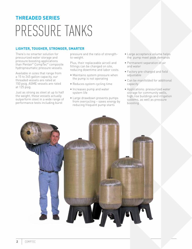
LIGHTER, TOUGHER, STRONGER, SMARTERThere’s no smarter solution for pressurized water storage and pressure boosting applications than Pentair® CompTec® composite hydropneumatic pressure vessels. Available in sizes that range from a 15 to 245 gallon capacity, our threaded vessels are rated at 150 psig. ASME vessels are rated at 125 psig.Just as strong as steel at up to half the weight, these vessels actually outperform steel in a wide range of performance tests including burst
pressure and the ratio of strength-to-weight.Plus, their replaceable aircell and fittings can be changed on site, reducing downtime and labor costs.• Maintains system pressure when
the pump is not operating• Reduces system cycling time• Increases pump and water
system life• Large drawdown prevents pumps
from overcycling – saves energy by reducing frequent pump starts
• Large acceptance volume helps the pump meet peak demands
• Permanent separation of air and water
• Factory pre-charged and field adjustable
• Can be manifolded for additional capacity
• Applications: pressurized water storage for community wells, high rise buildings and irrigation systems, as well as pressure boosting
COMPOS I T E W ATER S Y STEM PRESSURE TANKS 3
OPERATING SPECIFICATIONS
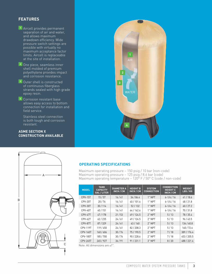
1 Aircell provides permanent separation of air and water, and allows maximum drawdown efficiency. Wide pressure switch settings are possible with virtually no maximum acceptance factor limits. Aircell is replaceable at the site of installation.
2 One piece, seamless inner shell molded of premium polyethylene provides impact and corrosion resistance.
3 Outer shell is constructed of continuous fiberglass strands sealed with high grade epoxy resin.
4 Corrosion resistant base allows easy access to bottom connection for installation and field service.
Stainless steel connection is both tough and corrosion resistant.
ASME SECTION X CONSTRUCTION AVAILABLE
FEATURES
Maximum operating pressure – 150 psig / 10 bar (non-code)Maximum operating pressure – 125 psig / 8.6 bar (code)Maximum operating temperature – 120° F / 50° C (code / non-code)
MODELTANK
CAPACITYGAL / LITER
DIAMETER AINCH / CM
HEIGHT BINCH / CM
SYSTEM CONNECTION
CONNECTION HEIGHT C INCH / CM
WEIGHTLBS / KG
CPV-15T 15 / 57 16 / 41 34 / 86.4 1" NPT 6-1/4 / 16 41 / 18.6CPV-20T 20 / 76 16 / 41 40 / 101.6 1" NPT 6-1/4 / 16 48 / 21.8CPV-30T 30 / 114 16 / 41 52 / 132 1" NPT 6-1/4 / 16 60 / 27.2CPV-40T 40 / 151 16 / 41 64 / 162.6 1" NPT 6-1/4 / 16 70 / 31.8CPV-47T 47 / 178 21 / 53 49 / 124.5 2" NPT 5 / 13 78 / 35.4CPV-62T 62 / 235 24 / 61 49 / 124.5 2" NPT 5 / 13 96 / 43.5CPV-87T 87 / 329 24 / 61 63 / 160 2" NPT 5 / 13 134 / 60.8
CPV-119T 119 / 450 24 / 61 82 / 208.3 2" NPT 5 / 13 160 / 72.6CPV-160T 160 / 606 30 / 76 75 / 190.5 2" NPT 7 / 18 389 / 176.4CPV-185T 185 / 700 30 / 76 90 / 228.6 2" NPT 7 / 18 453 / 205.5CPV-245T 245 / 927 36 / 91 91 / 231.1 3" NPT 8 / 20 488 / 221.4
Note: All dimensions are ±1".
1
2
3
4
WATER
A
B
C
AIR
4 COMPTEC
PRESSURE TANKSFLANGED SERIES
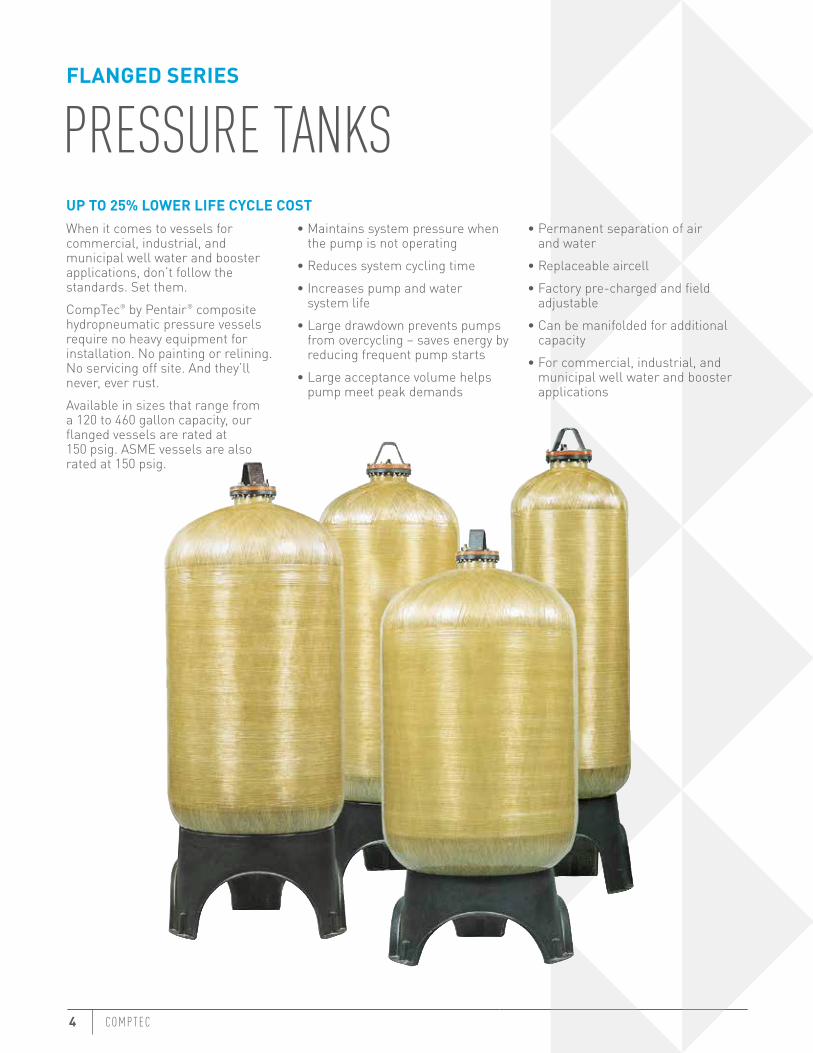
UP TO 25% LOWER LIFE CYCLE COSTWhen it comes to vessels for commercial, industrial, and municipal well water and booster applications, don’t follow the standards. Set them.CompTec® by Pentair® composite hydropneumatic pressure vessels require no heavy equipment for installation. No painting or relining. No servicing off site. And they’ll never, ever rust.Available in sizes that range from a 120 to 460 gallon capacity, our flanged vessels are rated at 150 psig. ASME vessels are also rated at 150 psig.
• Maintains system pressure when the pump is not operating
• Reduces system cycling time• Increases pump and water
system life• Large drawdown prevents pumps
from overcycling – saves energy by reducing frequent pump starts
• Large acceptance volume helps pump meet peak demands
• Permanent separation of air and water
• Replaceable aircell• Factory pre-charged and field
adjustable• Can be manifolded for additional
capacity• For commercial, industrial, and
municipal well water and booster applications
COMPOS I T E W ATER S Y STEM PRESSURE TANKS 5
OPERATING SPECIFICATIONS
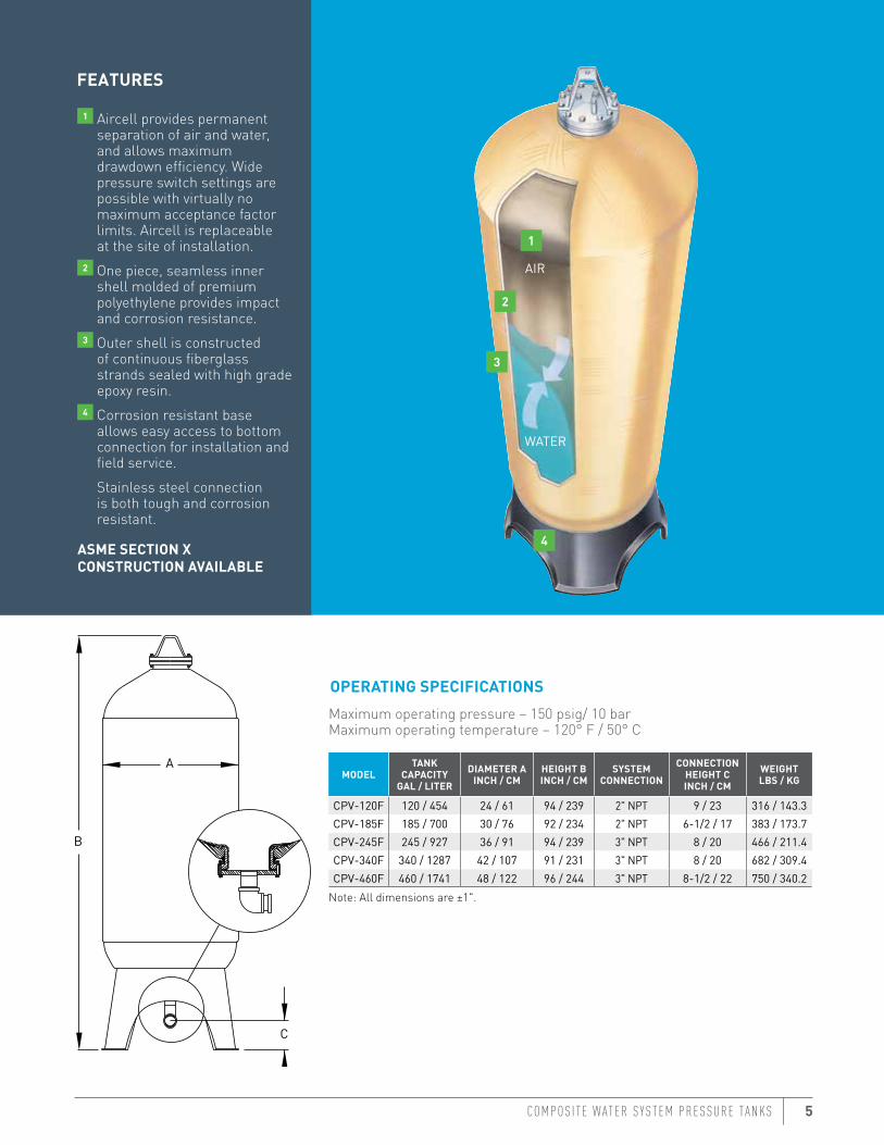
1 Aircell provides permanent separation of air and water, and allows maximum drawdown efficiency. Wide pressure switch settings are possible with virtually no maximum acceptance factor limits. Aircell is replaceable at the site of installation.
2 One piece, seamless inner shell molded of premium polyethylene provides impact and corrosion resistance.
3 Outer shell is constructed of continuous fiberglass strands sealed with high grade epoxy resin.
4 Corrosion resistant base allows easy access to bottom connection for installation and field service.
Stainless steel connection is both tough and corrosion resistant.
ASME SECTION X CONSTRUCTION AVAILABLE
FEATURES
Maximum operating pressure – 150 psig/ 10 barMaximum operating temperature – 120° F / 50° C
MODELTANK
CAPACITYGAL / LITER
DIAMETER AINCH / CM
HEIGHT BINCH / CM
SYSTEM CONNECTION
CONNECTION HEIGHT C INCH / CM
WEIGHTLBS / KG
CPV-120F 120 / 454 24 / 61 94 / 239 2" NPT 9 / 23 316 / 143.3CPV-185F 185 / 700 30 / 76 92 / 234 2" NPT 6-1/2 / 17 383 / 173.7CPV-245F 245 / 927 36 / 91 94 / 239 3" NPT 8 / 20 466 / 211.4CPV-340F 340 / 1287 42 / 107 91 / 231 3" NPT 8 / 20 682 / 309.4CPV-460F 460 / 1741 48 / 122 96 / 244 3" NPT 8-1/2 / 22 750 / 340.2
Note: All dimensions are ±1".
1
2
3
4
WATER
A
B
C
AIR
6 COMPTEC
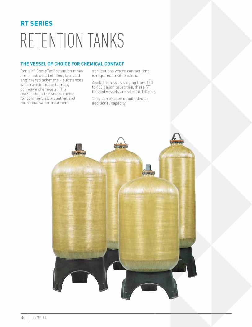
RETENTION TANKSRT SERIES
THE VESSEL OF CHOICE FOR CHEMICAL CONTACTPentair® CompTec® retention tanks are constructed of fiberglass and engineered polymers – substances which are immune to many corrosive chemicals. This makes them the smart choice for commercial, industrial and municipal water treatment
applications where contact time is required to kill bacteria.Available in sizes ranging from 120 to 460 gallon capacities, these RT flanged vessels are rated at 150 psig.They can also be manifolded for additional capacity.
COMPOS I T E W ATER S Y STEM PRESSURE TANKS 7
OPERATING SPECIFICATIONS
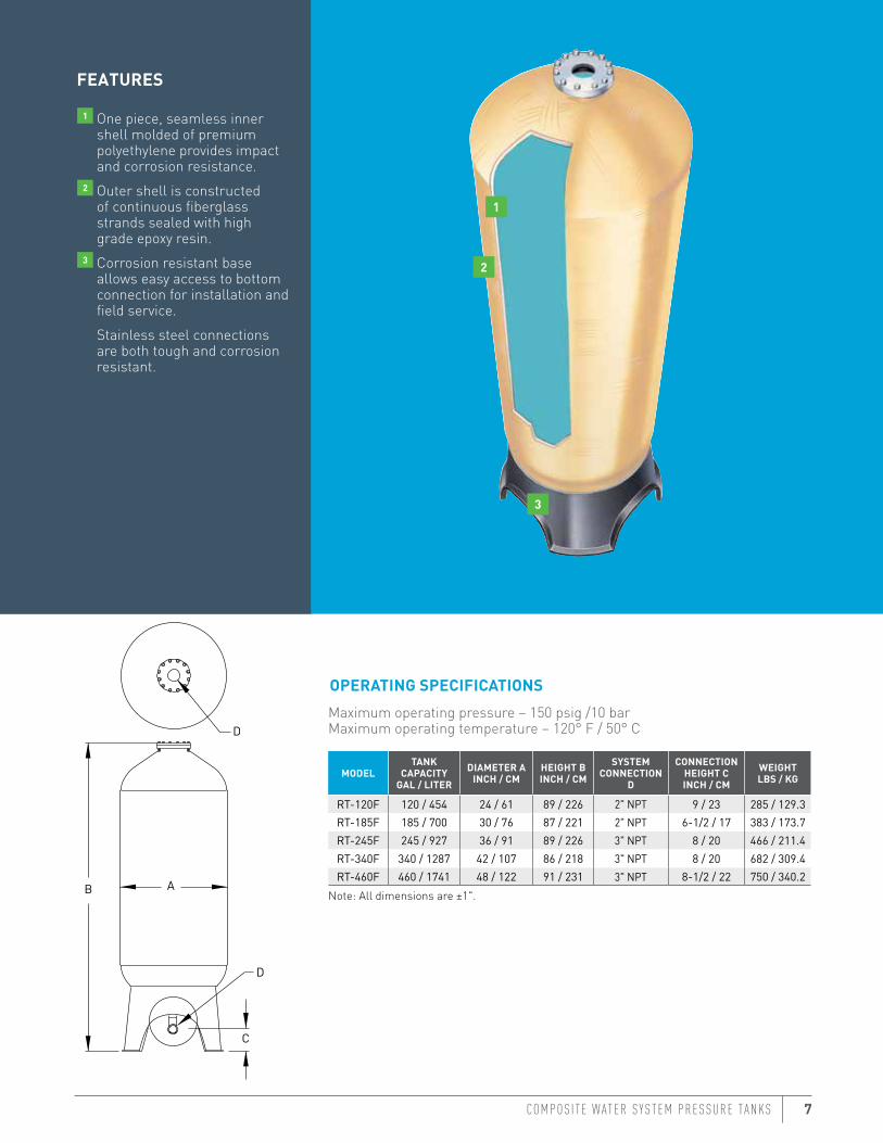
1 One piece, seamless inner shell molded of premium polyethylene provides impact and corrosion resistance.
2 Outer shell is constructed of continuous fiberglass strands sealed with high grade epoxy resin.
3 Corrosion resistant base allows easy access to bottom connection for installation and field service.
Stainless steel connections are both tough and corrosion resistant.
FEATURES
Maximum operating pressure – 150 psig /10 barMaximum operating temperature – 120° F / 50° C
MODELTANK
CAPACITYGAL / LITER
DIAMETER AINCH / CM
HEIGHT BINCH / CM
SYSTEM CONNECTION
D
CONNECTION HEIGHT C INCH / CM
WEIGHTLBS / KG
RT-120F 120 / 454 24 / 61 89 / 226 2" NPT 9 / 23 285 / 129.3RT-185F 185 / 700 30 / 76 87 / 221 2" NPT 6-1/2 / 17 383 / 173.7RT-245F 245 / 927 36 / 91 89 / 226 3" NPT 8 / 20 466 / 211.4RT-340F 340 / 1287 42 / 107 86 / 218 3" NPT 8 / 20 682 / 309.4RT-460F 460 / 1741 48 / 122 91 / 231 3" NPT 8-1/2 / 22 750 / 340.2
Note: All dimensions are ±1".
1
2
3
AB
C
D
D
8 COMPTEC
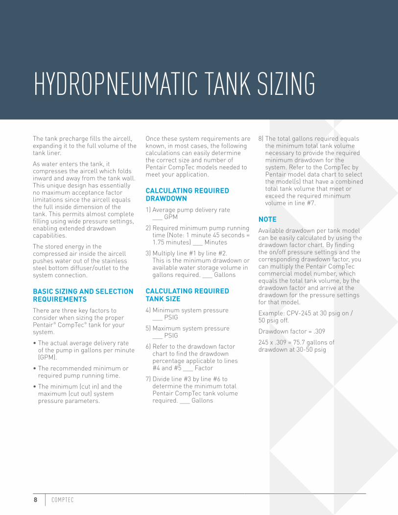
HYDROPNEUMATIC TANK SIZINGThe tank precharge fills the aircell, expanding it to the full volume of the tank liner.As water enters the tank, it compresses the aircell which folds inward and away from the tank wall. This unique design has essentially no maximum acceptance factor limitations since the aircell equals the full inside dimension of the tank. This permits almost complete filling using wide pressure settings, enabling extended drawdown capabilities.The stored energy in the compressed air inside the aircell pushes water out of the stainless steel bottom diffuser/outlet to the system connection.
BASIC SIZING AND SELECTION REQUIREMENTSThere are three key factors to consider when sizing the proper Pentair® CompTec® tank for your system.• The actual average delivery rate
of the pump in gallons per minute (GPM).
• The recommended minimum or required pump running time.
• The minimum (cut in) and the maximum (cut out) system pressure parameters.
Once these system requirements are known, in most cases, the following calculations can easily determine the correct size and number of Pentair CompTec models needed to meet your application.
CALCULATING REQUIRED DRAWDOWN1) Average pump delivery rate
___ GPM2) Required minimum pump running
time (Note: 1 minute 45 seconds = 1.75 minutes) ___ Minutes
3) Multiply line #1 by line #2. This is the minimum drawdown or available water storage volume in gallons required. ___ Gallons
CALCULATING REQUIRED TANK SIZE4) Minimum system pressure
___ PSIG5) Maximum system pressure
___ PSIG6) Refer to the drawdown factor
chart to find the drawdown percentage applicable to lines #4 and #5 ___ Factor
7) Divide line #3 by line #6 to determine the minimum total Pentair CompTec tank volume required. ___ Gallons
8) The total gallons required equals the minimum total tank volume necessary to provide the required minimum drawdown for the system. Refer to the CompTec by Pentair model data chart to select the model(s) that have a combined total tank volume that meet or exceed the required minimum volume in line #7.
NOTEAvailable drawdown per tank model can be easily calculated by using the drawdown factor chart. By finding the on/off pressure settings and the corresponding drawdown factor, you can multiply the Pentair CompTec commercial model number, which equals the total tank volume, by the drawdown factor and arrive at the drawdown for the pressure settings for that model.Example: CPV-245 at 30 psig on / 50 psig off.Drawdown factor = .309245 x .309 = 75.7 gallons of drawdown at 30-50 psig
COMPOS I T E W ATER S Y STEM PRESSURE TANKS 9
MAXIMUM (CUT-OUT)
TANK PRESSURE
(PSIG)
MINIMUM (CUT-IN) PRESSURE
10 15 20 25 30 35 40 45 50 55 60 65 70 75 80 85 90 95 100 105 110 115 120 125 130 135 140 145
30 .447 .336 .224 .11235 .503 .402 .302 .201 .10140 .548 .457 .366 .274 .183 .09145 .586 .503 .419 .335 .251 .168 .08450 .618 .541 .464 .386 .309 .232 .155 .07755 .646 .574 .502 .430 .359 .287 .215 .143 .07260 .669 .602 .535 .469 .402 .335 .268 .201 .134 .06765 .690 .627 .565 .502 .439 .376 .314 .251 .188 .125 .06370 .708 .649 .590 .531 .472 .413 .354 .295 .236 .177 .118 .05975 .725 .669 .613 .557 .502 .446 .390 .334 .279 .223 .167 .111 .05680 .739 .686 .634 .581 .528 .475 .422 .370 .317 .264 .211 .158 .106 .05385 752 .702 .652 .602 .552 .502 .451 .401 .351 .301 .251 .201 .150 .100 .05090 .764 .716 .669 .621 .573 .525 .478 .430 .382 .334 .287 .239 .191 .143 .096 .04895 .775 .729 .684 .638 .593 .547 .501 .456 .410 .385 .319 .273 .228 .182 .137 .091 .046
100 .785 .741 .697 .654 .610 .567 .523 .480 .436 .392 .349 .305 .262 .218 .174 .131 .087 .044105 .794 .752 .710 .668 .627 .585 .543 .501 .459 .418 .376 .334 .292 .251 .209 .167 .125 .084 .042110 .802 .762 .722 .682 .642 .601 .561 .521 .481 .441 .401 .361 .321 .281 .241 .200 .160 .120 .080 .040115 .810 .771 .732 .694 .655 .617 .587 .540 .501 .463 .424 .386 .347 .308 .270 .231 .193 .154 .116 .077 .039120 .817 .780 .742 .705 .668 .631 .594 .557 .520 .483 .445 .408 .371 .334 .297 .260 .223 .186 .148 .111 .074 .037125 .823 .787 .752 .716 .680 .644 .608 .573 .537 .501 .465 .429 .394 .358 .322 .286 .251 .215 .179 .143 .107 .072 .036130 .829 .795 .760 .726 .691 .657 .622 .587 .553 .518 .484 .449 .415 .380 .346 .311 .276 .242 .207 .173 .138 .104 .059 .035135 .835 .802 .768 .735 .701 .668 .635 .601 .568 .534 .501 .468 .434 .401 .367 .334 .301 .267 .234 .200 .167 .134 .100 .067 .033140 .840 .808 .776 .743 .711 .679 .646 .614 .582 .549 .517 .485 .452 .420 .388 .356 .323 .291 .259 .226 .194 .162 .129 .097 .065 .032145 .845 .814 .783 .751 .720 .689 .657 .626 .595 .564 .532 .501 .470 .438 .407 .376 .344 .313 .282 .250 .219 .188 .157 .125 .094 .063 .031150 .850 .820 .789 .759 .729 .698 .668 .638 .607 .577 .546 .516 .486 .455 .425 .395 .364 .334 .304 .279 .243 .213 .182 .152 .121 .091 .061 .030
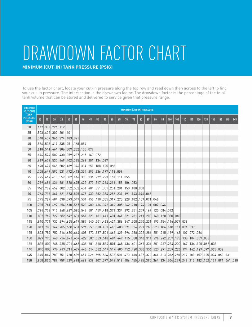
DRAWDOWN FACTOR CHARTMINIMUM (CUT-IN) TANK PRESSURE (PSIG)
To use the factor chart, locate your cut-in pressure along the top row and read down then across to the left to find your cut-in pressure. The intersection is the drawdown factor. The drawdown factor is the percentage of the total tank volume that can be stored and delivered to service given that pressure range.
10 COMPTEC
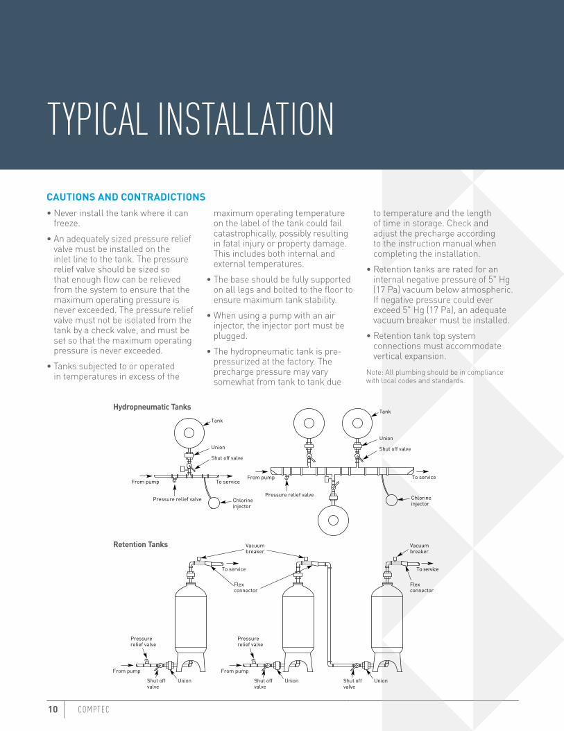
TYPICAL INSTALLATIONCAUTIONS AND CONTRADICTIONS• Never install the tank where it can
freeze.• An adequately sized pressure relief
valve must be installed on the inlet line to the tank. The pressure relief valve should be sized so that enough flow can be relieved from the system to ensure that the maximum operating pressure is never exceeded. The pressure relief valve must not be isolated from the tank by a check valve, and must be set so that the maximum operating pressure is never exceeded.
• Tanks subjected to or operated in temperatures in excess of the
maximum operating temperature on the label of the tank could fail catastrophically, possibly resulting in fatal injury or property damage. This includes both internal and external temperatures.
• The base should be fully supported on all legs and bolted to the floor to ensure maximum tank stability.
• When using a pump with an air injector, the injector port must be plugged.
• The hydropneumatic tank is pre-pressurized at the factory. The precharge pressure may vary somewhat from tank to tank due
to temperature and the length of time in storage. Check and adjust the precharge according to the instruction manual when completing the installation.
• Retention tanks are rated for an internal negative pressure of 5" Hg (17 Pa) vacuum below atmospheric. If negative pressure could ever exceed 5" Hg (17 Pa), an adequate vacuum breaker must be installed.
• Retention tank top system connections must accommodate vertical expansion.
Note: All plumbing should be in compliance with local codes and standards.
Chlorineinjector
Pressure relief valve
Pressurerelief valve
From pump To service
Tank
Union
Shut off valve
UnionShut offvalve
Pressure relief valve
From pump
Pressurerelief valve
UnionShut offvalve
UnionShut offvalve
From pump
From pump
To service To service
Vacuumbreaker
Flexconnector
Vacuumbreaker
Flexconnector
To service
Tank
Union
Shut off valve
Chlorineinjector
Retention Tanks
Hydropneumatic Tanks
COMPOS I T E W ATER S Y STEM PRESSURE TANKS 11
GENERAL SPECIFICATION LANGUAGEThe hydropneumatic tank shall be a pre-pressurized and sealed vessel (the retention tank shall be a sealed vessel) consisting of a composite design of a polyethylene seamless liner, reinforced with continuous strands of fiberglass covered with a two-part epoxy resin system.
SHORT FORM SPECIFICATIONSThe contractor shall provide fiberglass/composite pressure rated water system storage tanks with a diameter of ___" and overall length of ___" constructed of non-corrosive materials according to the features and dimensions shown on the drawings. The total tank capacity shall be ___ gallons/ ___ litres.The tanks shall have a maximum operating pressure of ____ PSIG and a maximum operating temperature of 120° Fahrenheit. The laminate outer shell shall be an epoxy and continuous strand fiberglass matrix. The liner shall be seamless polyethylene as manufactured by Pentair®
The pressure tanks shall meet a design safety factor of 4 to 1 (5 to 1 for ASME) for minimum burst pressure.
LONG FORM SPECIFICATIONSPart I. Quality Standards1.01 Acceptable manufacturers - Pentair Pump Group.
Part II. Performance Standards2.01 The maximum operating pressure of the tank shall be ___ PSIG and designed with a safety factor of 4 to 1 (5 to 1 for ASME) for minimum burst pressure.2.02 The maximum operating temperature of the tank shall be rated at 120° Fahrenheit.2.03 The tank shall be designed to pass a pressure cycle test of 250,000 cycles without failure. The test will cycle from 0 psi to the maximum operating pressure for that vessel.2.04 The tank shall be capable of withstanding negative pressure up to 5" Hg.
Part III. Inner Shell3.01 The tank inner shell shall be constructed of seamless polyethylene material.3.02 The tank inner shell will isolate the fluid contents of the tank to eliminate corrosion, intrusion or reaction.
Part IV. Outer Fiberglass Shell4.01 The outer tank shell shall be constructed of continuous fiberglass roving.4.02 The laminate matrix shall be epoxy with a glass transition temperature of 30° Fahrenheit higher than maximum use temperature. Laminate glass volume shall be no less than 70%.
Part V. Capacity and Dimensions5.01 The holding capacity of the tank inner shell shall be ___ gallons or ___ litres.5.02 The tank shall have a diameter of ___" and an overall length of ___".
Part IV. Tank Openings6.01 Threaded tank openings shall be an NPT thread specification.
Part VII. Tank Support Base7.01 The tank support base shall allow accessibility to the bottom of the tank if required for servicing and maintenance.7.02 Minimum tank clearance at the bottom of the tank shall be ___" as shown in the drawings provided.
12 COMPTEC
ASME SECTION X FOR FRPSection X of the ASME Pressure Vessel Code pertains to fiberglass reinforced plastic (FRP) pressure vessels. The code requirements for the design and manufacture of these composite pressure vessels are as complex as those for metal, but vastly different. A Class 1 ASME pressure vessel is one which is qualified through destructive testing of a prototype.Section X requires that a Class 1 design be qualified with a test of a prototype vessel. This prototype vessel is carefully reviewed and inspected by a third-party certified inspector. The vessel must be cycled 100,000 times over a pressure range of atmosphere-to-design pressure.Following this, the prototype vessel must withstand a hydrostatic burst test of not less than six times design pressure. An exception to the 100,000-cycle requirement is made for vessels constructed of uncut filaments. For these vessels, the classification is designed for a 5-to-1 safety factor, requiring 33,000 atmosphere-to-design pressure cycles. These uncut filament vessels must then withstand a hydrostatic
burst test of not less than five times design pressure. The code also requires the burst test pressure be applied very slowly, making for a very rigorous stress/rupture-type test.
DIFFERENT FOR METAL VESSELSBecause buyers or specifiers are familiar with the requirements of the ASME code for metal vessels, it is not uncommon to receive requests for design calculations. However, the Class 1 pressure vessels are not subject to the same design criteria as metal vessels, because of the prototype destructive qualification. Thus, design calculations alone are not meaningful.What is meaningful to specifiers and buyers is that the prototype vessel is designed to the strict requirements of Section X; it complies with exhaustive qualification testing; and each vessel is made to the exact standards of the prototype and passes proof testing before shipment.
The proof test for an ASME composite pressure vessel requires pressurization to one and one-half times the design pressure. Also, the vessel cannot vary more than 5 parts per 100 in volume during expansion under pressure and it meets the exact weight limitations set by the prototype vessel.Certified producers of composite pressure vessels under ASME Section X must develop and submit pressure vessel fabrication technologies to the Pressure Vessel Committee of the ASME. Fabricators must submit a design basis of each size of a pressure vessel, indicating diameter or length, to the ASME committee. A prototype vessel of each size is produced and proven to meet all requirements of the code by a certified third party.Each subsequent composite pressure vessel is then produced as an exact replica of the prototype, again certified by third-party inspection. The result of this testing and inspection is a composite pressure vessel that complies completely with the ASME Pressure Vessel Code and carries the “RP” stamp.
Section X of the ASME Pressure Vessel Code pertains to FRP pressure vessels. The code requirements for the design and manufacture of these composite pressure vessels are as complex as those for metal, but vastly different.

COMPOS I T E W ATER S Y STEM PRESSURE TANKS iii

FILTRATION & PROCESS5730 NORTH GLEN PARK ROAD, MILWAUKEE, WI 53209P: 262.238.4400 | F: 262.238.4404 | WWW.PENTAIRAQUA.COM | CUSTOMER CARE: 800.279.9404
All Pentair trademarks and logos are owned by Pentair, Inc. or its affiliates. All other registered and unregistered trademarks and logos are the property of their respective owners. Because we are continuously improving our products and services, Pentair reserves the right to change specifications without prior notice. Pentair is an equal opportunity employer.WM311 REV D JL14 © 2014 Pentair Residential Filtration, LLC. All Rights Reserved.