computation and visualization of patch geometries for the
TRANSCRIPT

Procedia CIRP 21 ( 2014 ) 437 – 442
Available online at www.sciencedirect.com
2212-8271 © 2014 Elsevier B.V. This is an open access article under the CC BY-NC-ND license (http://creativecommons.org/licenses/by-nc-nd/3.0/).Selection and peer-review under responsibility of the International Scientific Committee of “24th CIRP Design Conference” in the person of the Conference Chairs Giovanni Moroni and Tullio Toliodoi: 10.1016/j.procir.2014.03.133
ScienceDirect
24th CIRP Design Conference
Computation and visualization of patch geometries for the design of carbonfiber reinforced parts at early design stages
Daniel Kleina, Kaja Schelera, Sandro Wartzacka
aChair for Engineering Design, University of Erlangen-Nuremberg, Martensstrasse 9, Erlangen and 91058, Germany∗ Corresponding author. Tel.: +49-9131-85-232-16; fax: +49-9131-85-232-18. E-mail address: [email protected]
Abstract
The market for carbon fibers is forecast to experience a double-digit growth over the next years. The reason for this development can be found
in the special characteristics of Carbon Fiber Reinforced Plastics (CFRP) like high stiffness and strength at very low weight which make this
composite an ideal material for lightweight design. However, the design of parts made of CFRP is a tightrope walk between costs, mechanical
characteristics and manufacturability for product developers. On the one hand, the mechanical properties are highly dependent on the ideal fiber
orientation within the part and the unique material characteristics can only be exploited with a suitable fiber orientation, but on the other hand, the
ideal fiber orientation is often not manufacturable or the required manufacturing technique is too expensive.
Therefore, a novel algorithm to support product developers in finding a manufacturable fiber orientation or patch layout which is as close as
possible to the ideal fiber orientation is introduced. This algorithm computes and highlights areas with constant fiber orientation (=cluster) based
upon the ideal fiber alignment from the CAIO method. With the help of the visualization of the clusters, product developers can be supported in
the decision for the best patch placement and geometry as well as in choosing the best manufacturing technique. It is important to point out that
the algorithm is intended for endless fiber reinforced parts only.c© 2014 The Authors. Published by Elsevier B.V.
Selection and peer-review under responsibility of the International Scientific Committee of “24th CIRP Design Conference” in the person of the
Conference Chairs Giovanni Moroni and Tullio Tolio.
Keywords: Lightweight design; Early design stages; Endless fibre reinforced composites
Nomenclature
BFRP Basalt Fiber Reinforced Plastic
CAIO Computer Aided Internal Optimization
CFRP Carbon Fiber Reinforced Plastic
FEA Finite Element Analysis
GFRP Glass Fiber Reinforced Plastic
1. Composites - curse and blessing
With a forecast annual growth rate of about 17 % and a mar-
ket value of $ 7.3 billion by the year 2017, the market for CFRP
is experiencing a very positive development [1]. And even be-
yond the year 2017 the global carbon fiber market is forecast to
increase considerably from 118.000 t in 2017 to 500.000 t by
the year 2030 [1,2].
The reason for this tremendous development can be found in the
unique characteristics of CFRP, like high stiffness and strength
at low weight and the resulting lightweight potential, which of-
fers the opportunity to solve problems in many different indus-
tries. Nevertheless, CFRP has not been established as a ma-
terial for mass products yet, because manufacturers are facing
various problems. For example, the material price for CFRP
is much higher than for conventional lightweight materials like
aluminium. Experts estimate the price for CFRP parts at 570 %
of parts made of steel [3]. Additionally, the production of parts
made of CFRP can only hardly be automated and the cycle
times are very high resulting in high production costs, which
makes the use of CFRP very expensive and unsuitable for mass
products. Another very important characteristic of CFRP, or
composites in general, is the dependency on the correct fiber
alignment. Only if the fibers are oriented correctly (see chapter
3) the promised lightweight potential can be fully exploited and
the higher material prize and production costs can be justified.
2. The crux of fiber alignment
For the design of composite parts it is very important to
take into account the dependency of the mechanical behavior
of composites on the fiber alignment. Even the slightest devia-
© 2014 Elsevier B.V. This is an open access article under the CC BY-NC-ND license (http://creativecommons.org/licenses/by-nc-nd/3.0/).Selection and peer-review under responsibility of the International Scientifi c Committee of “24th CIRP Design Conference” in the person of the Conference Chairs Giovanni Moroni and Tullio Tolio

438 Daniel Klein et al. / Procedia CIRP 21 ( 2014 ) 437 – 442
439 Daniel Klein et al. / Procedia CIRP 21 ( 2014 ) 437 – 442
Considering the displacement in y’-directions as an indicator
for the part stiffness, the stiffness of the b-pillar can be increased
about 70.8 % in comparison with the unidirectional fiber layout
by using the CAIO method for the computation of the ideal
fiber direction. Another big advantage of the CAIO method is
that this method is invariant from the coordinate system and can
be used for arbitrary structures without any additional effort [4].
3.2. The need for a patch algorithm
Besides the good stiffness characteristics, the fiber layout
computed with the help of the CAIO method has one big dis-
advantage. Since the element coordinate system within each
element can be changed to find the best fiber orientation with
respect to the structural performance, the CAIO algorithm re-
sults in a very complex fiber layout which can even differ from
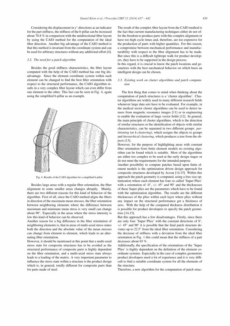
one element to the other. This fact can be seen in Fig. 4, again
using the simplified b-pillar as an example.
Fig. 4. Results of the CAIO algorithm for a simplified b-pillar
Besides large areas with a regular fiber orientation, the fiber
alignment in some smaller areas changes abruptly. Mainly,
there are two different reasons for this kind of behavior of the
algorithm. First of all, since the CAIO method aligns the fibers
in direction of the maximum mean stresses, the fiber orientation
between neighboring elements where the difference between
maximum and minimum mean stress is very small can change
about 90◦. Especially in the areas where the stress intensity is
low this kind of behavior can be observed.
Another reason for a big difference in the fiber orientation of
neighboring elements is, that in areas of multi-axial stress states
both the direction and the absolute value of the mean stresses
can change from element to element, which leads to an alter-
nating fiber orientation.
However, it should be mentioned at this point that a multi-axial
stress state for composite structures has to be avoided as the
structural performance of composite parts is highly dependent
on the fiber orientation, and a multi-axial stress state always
leads to a loading of the matrix. A very important parameter to
influence the stress state within a structure is the product design
which is, in general, totally different for composite parts than
for parts made of steel.
The result of the complex fiber layout from the CAIO method is
the fact that current manufacturing techniques either do not of-
fer the freedom to produce parts with this complex alignment or
have too high cycle times and, therefore, are too expensive for
the production of parts with higher quantities. For this reason,
a compromise between mechanical performance and manufac-
turability with respect to the fiber alignment has to be made.
But since this is a difficult tightrope walk for product develop-
ers, they have to be supported in the design process.
In this regard, it is crucial to know the patch locations and ge-
ometries with the best mechanical behavior on which basis an
intelligent design can be chosen.
3.3. Existing work on cluster algorithms and patch computa-tion
The first thing that comes to mind when thinking about the
computation of patch structures is a ‘cluster algorithm’. Clus-
ter algorithms are widely used in many different research fields
whenever large data sets have to be evaluated. For example, in
the medical sector cluster algorithms can be used to detect tu-
mors from magnetic resonance images [11] or in engineering
to enable the evaluation of large vector fields [12]. In general,
the main principle of cluster algorithms, which is the detection
of similar structures or the identification of objects with similar
characteristics, can be separated in two different groups: par-titioning (or k-clustering), which assigns the objects to groups
and hierarchical clustering, which produces a tree from the ob-
jects [13].
However, for the purpose of highlighting areas with constant
fiber orientation from finite element models no existing algo-
rithm can be found which is suitable. Most of the algorithms
are either too complex to be used at the early design stages or
do not meet the requirements for the intended purpose.
Another possibility to compute patches based upon finite el-
ement models is the optimization driven design approach for
composite structures developed by Altair [14,15]. Within this
approach the patch geometry is computed, using a free size op-
timization where each element has four so called ’Super Plies’
with a orientation of -0◦, +/- 45◦ and 90◦ and the thicknesses
of these Super plies are the parameters which have to be found
with the optimization algorithm. The results are the different
thicknesses of the plies within each layer where plies without
any impact on the structural performance get a thickness of
zero. With the help of the computed thickness distribution it
is possible for product developers to specify the patch geome-
tries [14,15].
But this approach has a few disadvantages. Firstly, since there
are only four ’Super Plies’ with the constant directions of 0◦,+/- 45◦ and 90◦ it is possible that the final patch structure de-
viates up to 22.5◦ from the ideal fiber orientation. Considering
the decrease of stiffness with a deviation from the ideal fiber
orientation in Fig. 1 this could mean that the stiffness of a part
decreases about 65 %.
Additionally, the specification of the orientations of the ’Super
Plies’ is highly dependent on the definition of the element co-
ordinate systems. Especially in the case of complex geometries
product developers need a lot of experience and it is very diffi-
cult to find a suitable coordinate system for all the elements of
the structure.
Therefore, a new algorithm for the computation of patch struc-

440 Daniel Klein et al. / Procedia CIRP 21 ( 2014 ) 437 – 442
tures will be introduced in the following. The main character-
istics of this new approach are that it is easy to use at the early
design stages, invariant from the chosen coordinate system as
it is based on the mean stresses and not restricted to previously
specified fiber orientations to have the maximum freedom in
design.
4. Introduction of a new patching algorithm
To walk the tightrope between structural performance and
manufacturability of composite parts the algorithm computes
patch geometries based on the fiber orientations from the CAIO
algorithm. With the help of the visualized patch geometries
product developers can create a manufacturable fiber layout
which is as close to the ideal fiber orientation as possible. It
is very important to point out, that even though the results in
this article are patch geometries which seem to be most appro-
priate for the handlamination technique, the algorithm does not
focus on one special manufacturing technique. The decision
which manufacturing technique has to be chosen is very diffi-
cult and has to be made for every part individually as the choice
depends on many different parameters like quantity, manufac-
turing costs, etc.
4.1. Explanation of the basic principle
The most important assumption is that within one patch the
fiber orientation does not change. Therefore, it is the task of the
algorithm to find areas where the fiber orientation is constant
(=cluster). The basic principle of the algorithm to accomplish
this task is shown in Fig. 5.
FEA-Model
CAIO method
Determination of neighboring elements
Comparison of fiber orientations
Elements added
Yes
Yes
Close cluster
Unclusteredelements left
END
Open a new cluster
No
No
Yes
Clu
ster
alg
orit
hm
1
2
3
4
5
Fig. 5. Basic principle of the algorithm
Before the algorithm can be used, a FEA model has to be
created and the fiber orientations have to be computed with the
help of the CAIO method. The inital step (1) of the algorithm is
to open a new cluster which is nothing else than the first patch
which is to be computed. Therefore, an element of the FEA
model is selected and in the second step (2) the neighbor ele-
ments are determined (see Fig.6).
Determination ofneighboring elements
Compare fibers and addelements if possible
Determination ofneighboring elements
= cluster element
= neighbor element
y
x
step 3 – first iterationstep 2 – first iteration step 2 – second iteration
Fig. 6. Visualization of the crucial steps of the algorithm
Since the fiber orientation within one patch has to be con-
stant, the orientation of each neighboring element is compared
to the first cluster element with the help of the angle of the fiber
orientation about the global coordinate system (3). If the dif-
ference lies within a given tolerance, the element is added to
the cluster and after the comparison it is checked whether any
new elements were added during the last step. In the case of a
positive feedback the algorithm goes on with step 2, again, oth-
erwise the cluster is closed (4) and it is checked whether there
are any unclustered elements left to form another cluster. The
algorithm is finished (5) when all elements are clustered and
the computed clusters can be visualized. The results for a plate
under tension is shown in Fig. 7.
a)
b)
x
y
Fig. 7. a) Fiber orientation from the CAIO method, b) Resulting clusters with a
tolerance of 10◦
By comparing the resulting fiber orientation from the CAIO
method and the proposed patch structure it becomes obvious
that the algorithm provides good results. Since the fiber orien-
tation in a large area of the plate is oriented in load direction
(= x-direction) this area could be manufactured with one single
patch whereas the area around the hole has to be manufactured
with four patches in order to get a patch layout close to the orig-
inal fiber orientation.
A very important task for the use of the algorithm is the choice
of a suitable tolerance field because the patch layout and, as a
consequence, the mechanical behavior of the part are highly de-
pendent on this tolerance field. In Fig. 8 the dependency of the
441 Daniel Klein et al. / Procedia CIRP 21 ( 2014 ) 437 – 442
part stiffness on the chosen tolerance for the plate from Fig. 7
is shown.
0 5 10 15 20 25 30Tolerance in degrees
Rel
ativ
e pa
rtst
iffn
ess CAIO
PatchedUniaxial
1
0.95
0.9
0.85
0.8
0.75
0.7
16 clusters
38 clusters
Fig. 8. Comparison of the part stiffness between a structure with a patched and
an uniaxial fiber layout
As it is indicated in the diagram, the relative part stiffness
decreases with increasing tolerance because the deviation from
the ideal fiber orientation increases, too. But on the other hand
the choice of a strict tolerance criterion leads to a fiber layout
with many different patches which can only be manufactured
at high expenses. For example, the result for the plate with
a tolerance of 10◦ is a fiber layout with 16 different clusters,
whereas with a tolerance of 5◦ the number of clusters increases
to 38 clusters. Therefore, the choice of the tolerance is always a
compromise between mechanical characteristics and manufac-
turability. Since the computation time for the algorithm even for
more complex parts is very short, it is advisable to compute the
patch layout with different tolerances and evaluate the relevant
mechanical part characteristics with respect to the variation of
the tolerance criterion.
Another aspect which was observed during the implementation
of the algorithm is the dependency of the choice of the starting
element on the algorithm. For this reason a random starting el-
ement selection was implemented and the patch geometries as
well as the mechanical behaviour of the part were evaluated. In
this observation it could be proven that the dependency of the
choice of the starting element on the results of the algorithm is
negligible. The starting element can therefore be chosen arbi-
trarily.
4.2. Extension to 3-dimensional geometries
The basic principle of the algorithm could be explained with
the help of a 2-dimensional example. But most of the parts used
in composites structures are very complex 3-dimensional parts.
For this reason the algorithm will be extended to spatial struc-
tures within this chapter by a modification of step 3 in Fig. 5.
Since the normal directions of the element planes in
3-dimensional models are different, the neighbor elements have
to be rotated into the plane of the starting element until the nor-
mal directions of the two elements point into the same direction,
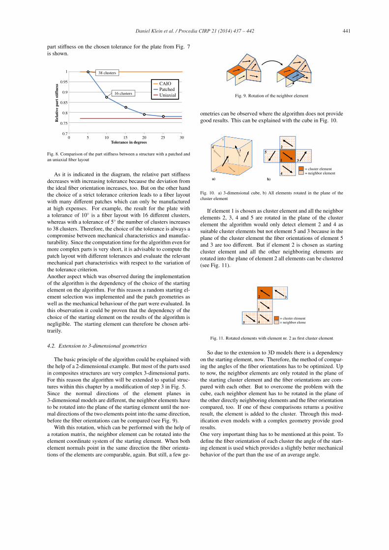
before the fiber orientations can be compared (see Fig. 9).
With this rotation, which can be performed with the help of
a rotation matrix, the neighbor element can be rotated into the
element coordinate system of the starting element. When both
element normals point in the same direction the fiber orienta-
tions of the elements are comparable, again. But still, a few ge-
Fig. 9. Rotation of the neighbor element
ometries can be observed where the algorithm does not provide
good results. This can be explained with the cube in Fig. 10.
a) b)
1 3
25
4= cluster element= neighbor element
Fig. 10. a) 3-dimensional cube, b) All elements rotated in the plane of the
cluster element
If element 1 is chosen as cluster element and all the neighbor
elements 2, 3, 4 and 5 are rotated in the plane of the cluster
element the algorithm would only detect element 2 and 4 as
suitable cluster elements but not element 5 and 3 because in the
plane of the cluster element the fiber orientations of element 5
and 3 are too different. But if element 2 is chosen as starting
cluster element and all the other neighboring elements are
rotated into the plane of element 2 all elements can be clustered
(see Fig. 11).
1
32
5 4= cluster element= neighbor eleme
Fig. 11. Rotated elements with element nr. 2 as first cluster element
So due to the extension to 3D models there is a dependency
on the starting element, now. Therefore, the method of compar-
ing the angles of the fiber orientations has to be optimized. Up
to now, the neighbor elements are only rotated in the plane of
the starting cluster element and the fiber orientations are com-
pared with each other. But to overcome the problem with the
cube, each neighbor element has to be rotated in the plane of
the other directly neighboring elements and the fiber orientation
compared, too. If one of these comparisons returns a positive
result, the element is added to the cluster. Through this mod-
ification even models with a complex geometry provide good
results.
One very important thing has to be mentioned at this point. To
define the fiber orientation of each cluster the angle of the start-
ing element is used which provides a slightly better mechanical
behavior of the part than the use of an average angle.
442 Daniel Klein et al. / Procedia CIRP 21 ( 2014 ) 437 – 442
4.3. Results of the algorithm
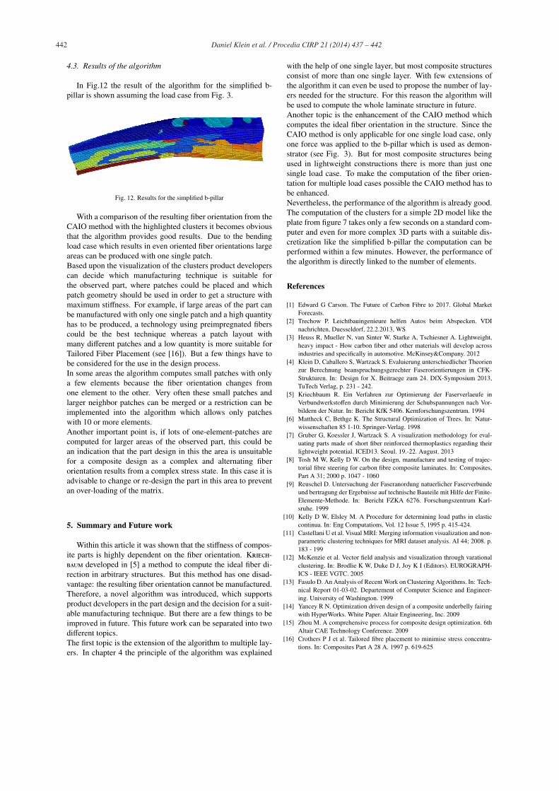
In Fig.12 the result of the algorithm for the simplified b-
pillar is shown assuming the load case from Fig. 3.
Fig. 12. Results for the simplified b-pillar
With a comparison of the resulting fiber orientation from the
CAIO method with the highlighted clusters it becomes obvious
that the algorithm provides good results. Due to the bending
load case which results in even oriented fiber orientations large
areas can be produced with one single patch.
Based upon the visualization of the clusters product developers
can decide which manufacturing technique is suitable for
the observed part, where patches could be placed and which
patch geometry should be used in order to get a structure with
maximum stiffness. For example, if large areas of the part can
be manufactured with only one single patch and a high quantity
has to be produced, a technology using preimpregnated fibers
could be the best technique whereas a patch layout with
many different patches and a low quantity is more suitable for
Tailored Fiber Placement (see [16]). But a few things have to
be considered for the use in the design process.
In some areas the algorithm computes small patches with only
a few elements because the fiber orientation changes from
one element to the other. Very often these small patches and
larger neighbor patches can be merged or a restriction can be
implemented into the algorithm which allows only patches
with 10 or more elements.
Another important point is, if lots of one-element-patches are
computed for larger areas of the observed part, this could be
an indication that the part design in this the area is unsuitable
for a composite design as a complex and alternating fiber
orientation results from a complex stress state. In this case it is
advisable to change or re-design the part in this area to prevent
an over-loading of the matrix.
5. Summary and Future work
Within this article it was shown that the stiffness of compos-
ite parts is highly dependent on the fiber orientation. Kriech-
baum developed in [5] a method to compute the ideal fiber di-
rection in arbitrary structures. But this method has one disad-
vantage: the resulting fiber orientation cannot be manufactured.
Therefore, a novel algorithm was introduced, which supports
product developers in the part design and the decision for a suit-
able manufacturing technique. But there are a few things to be
improved in future. This future work can be separated into two
different topics.
The first topic is the extension of the algorithm to multiple lay-
ers. In chapter 4 the principle of the algorithm was explained
with the help of one single layer, but most composite structures
consist of more than one single layer. With few extensions of
the algorithm it can even be used to propose the number of lay-
ers needed for the structure. For this reason the algorithm will
be used to compute the whole laminate structure in future.
Another topic is the enhancement of the CAIO method which
computes the ideal fiber orientation in the structure. Since the
CAIO method is only applicable for one single load case, only
one force was applied to the b-pillar which is used as demon-
strator (see Fig. 3). But for most composite structures being
used in lightweight constructions there is more than just one
single load case. To make the computation of the fiber orien-
tation for multiple load cases possible the CAIO method has to
be enhanced.
Nevertheless, the performance of the algorithm is already good.
The computation of the clusters for a simple 2D model like the
plate from figure 7 takes only a few seconds on a standard com-
puter and even for more complex 3D parts with a suitable dis-
cretization like the simplified b-pillar the computation can be
performed within a few minutes. However, the performance of
the algorithm is directly linked to the number of elements.
References
[1] Edward G Carson. The Future of Carbon Fibre to 2017. Global Market
Forecasts.
[2] Trechow P. Leichtbauingenieure helfen Autos beim Abspecken. VDI
nachrichten, Duesseldorf, 22.2.2013, WS
[3] Heuss R, Mueller N, van Sinter W, Starke A, Tschiesner A. Lightweight,
heavy impact - How carbon fiber and other materials will develop across
industries and specifically in automotive. McKinsey&Company. 2012
[4] Klein D, Caballero S, Wartzack S. Evaluierung unterschiedlicher Theorien
zur Berechnung beanspruchungsgerechter Faserorientierungen in CFK-
Strukturen. In: Design for X. Beitraege zum 24. DfX-Symposium 2013,
TuTech Verlag, p. 231 - 242.
[5] Kriechbaum R. Ein Verfahren zur Optimierung der Faserverlaeufe in
Verbundwerkstoffen durch Minimierung der Schubspannungen nach Vor-
bildern der Natur. In: Bericht KfK 5406. Kernforschungszentrum. 1994
[6] Mattheck C, Bethge K. The Structural Optimization of Trees. In: Natur-
wissenschaften 85 1-10. Springer-Verlag. 1998
[7] Gruber G, Koessler J, Wartzack S. A visualization methodology for eval-
uating parts made of short fiber reinforced thermoplastics regarding their
lightweight potential. ICED13. Seoul. 19.-22. August. 2013
[8] Tosh M W, Kelly D W. On the design, manufacture and testing of trajec-
torial fibre steering for carbon fibre composite laminates. In: Composites,
Part A 31; 2000 p. 1047 - 1060
[9] Reuschel D. Untersuchung der Faseranordung natuerlicher Faserverbunde
und bertragung der Ergebnisse auf technische Bauteile mit Hilfe der Finite-
Elemente-Methode. In: Bericht FZKA 6276. Forschungszentrum Karl-
sruhe. 1999
[10] Kelly D W, Elsley M. A Procedure for determining load paths in elastic
continua. In: Eng Computations, Vol. 12 Issue 5, 1995 p. 415-424.
[11] Castellani U et al. Visual MRI: Merging information visualization and non-
parametric clustering techniques for MRI dataset analysis. AI 44; 2008. p.
183 - 199
[12] McKenzie et al. Vector field analysis and visualization through varational
clustering. In: Brodlie K W, Duke D J, Joy K I (Editors). EUROGRAPH-
ICS - IEEE VGTC. 2005
[13] Fasulo D. An Analysis of Recent Work on Clustering Algorithms. In: Tech-
nical Report 01-03-02. Departement of Computer Science and Engineer-
ing. University of Washington. 1999
[14] Yancey R N. Optimization driven design of a composite underbelly fairing
with HyperWorks. White Paper. Altair Engineering, Inc. 2009
[15] Zhou M. A comprehensive process for composite design optimization. 6th
Altair CAE Technology Conference. 2009
[16] Crothers P J et al. Tailored fibre placement to minimise stress concentra-
tions. In: Composites Part A 28 A. 1997 p. 619-625