computational analysis of failure criteria of a multi
TRANSCRIPT

Computational analysis of failure criteria of a multi-storey steel frame exposed to fires: thermal vs. structuralEgle Rackauskaite, Panagiotis Kotsovinos, and Guillermo Rein

WHY? – Real Fires
NIST
Foad Ashtari
2A + P/A Alfonso Correas
WHY? – Traditional Design
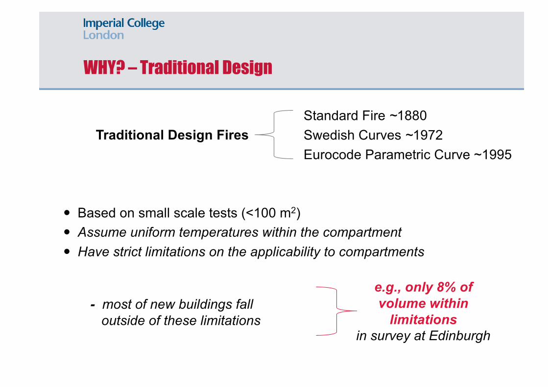
Traditional Design Fires
� Based on small scale tests (<100 m2)� Assume uniform temperatures within the compartment� Have strict limitations on the applicability to compartments
- most of new buildings fall outside of these limitations
Standard Fire ~1880 Swedish Curves ~1972Eurocode Parametric Curve ~1995
e.g., only 8% of volume within
limitations in survey at Edinburgh

Travelling Fires Methodology (iTFM)
• TFM - Stern-Gottfried, Law and Rein (2007-2012)
• iTFM - Rackauskaite, Hamel, Law and Rein (2015)
• Considers a family of fires → different % of floor areas engulfed in flames
• Takes into account highly non-uniformtemperature distributions

Travelling Fires Methodology (iTFM)
730°C641°C
548°C
AIM OF THE STUDY
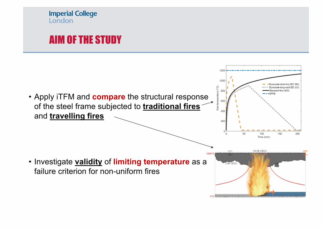
• Apply iTFM and compare the structural response of the steel frame subjected to traditional fires and travelling fires
• Investigate validity of limiting temperature as a failure criterion for non-uniform fires

INVESTIGATED STEEL FRAME
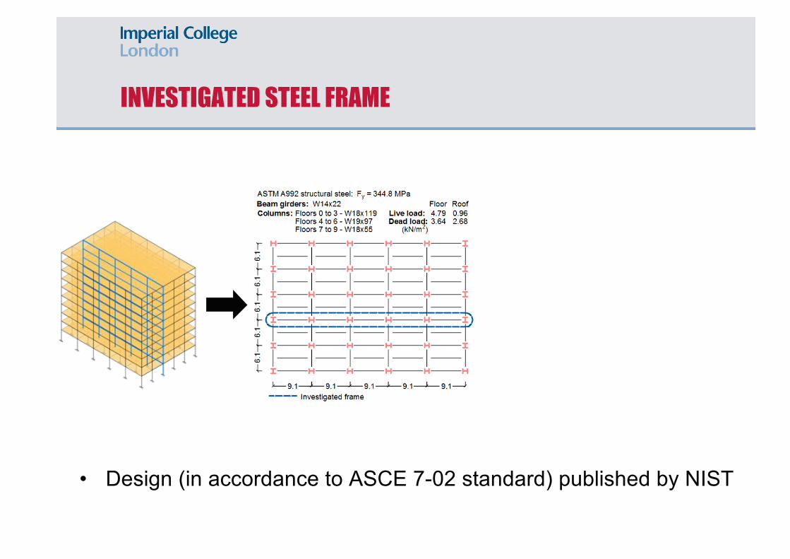
• Design (in accordance to ASCE 7-02 standard) published by NIST
INVESTIGATED STEEL FRAME
• Design (in accordance to ASCE 7-02 standard) published by NIST

INVESTIGATED STEEL FRAME
• Design (in accordance to ASCE 7-02 standard) published by NIST

FIRE SCENARIOS
4 travelling fires (TF)
- 2.5%, 10%, 25%, and 48%

FIRE SCENARIOS
4 travelling fires (TF)
- 2.5%, 10%, 25%, and 48%2 Eurocode (EC) parametric curves
- short-hot (SH) and long-cool (LC)
• Applied to every floor of the frame → 117 fire scenarios in total

THE MODEL
Structural analysis
• Finite Element Software LS-DYNA (explicit dynamic solver)
• Temperature dependent steel properties according to the Eurocode
Heat transfer
• Protected beams (60 min) and columns (120 min)
• Buchanan (2009):

• BM1: Gillie (2009)
• BM2: Cooke & Latham (1987)
• BM3: Rackauskaite & El-Rimawi (2015)
BENCHMARKING OF LS-DYNA

• BM1: Gillie (2009)
• BM2: Cooke & Latham (1987)
• BM3: Rackauskaite & El-Rimawi (2015)
BENCHMARKING OF LS-DYNA

FAILURE CRITERIA
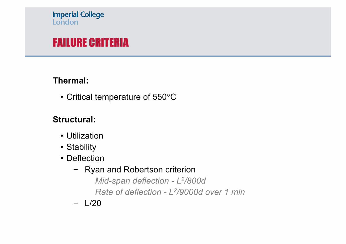
Thermal:
• Critical temperature of 550°C
Structural:
• Utilization• Stability• Deflection
− Ryan and Robertson criterionMid-span deflection - L2/800dRate of deflection - L2/9000d over 1 min
− L/20

FAILURE CRITERIA
Thermal:
• Critical temperature of 550°C
Structural:
• Utilization• Stability• Deflection
− Ryan and Robertson criterionMid-span deflection - L2/800dRate of deflection - L2/9000d over 1 min
− L/20550°C

FAILURE CRITERIA
Thermal:
• Critical temperature of 550°C
Structural:
• Utilization• Stability• Deflection
− Ryan and Robertson criterionMid-span deflection - L2/800dRate of deflection - L2/9000d over 1 min
− L/20

FAILURE CRITERIA
Thermal:
• Critical temperature of 550°C
Structural:
• Utilization• Stability• Deflection
− Ryan and Robertson criterionMid-span deflection - L2/800dRate of deflection - L2/9000d over 1 min
− L/200.2
FAILURE CRITERIA
Thermal:
• Critical temperature of 550°C
Structural:
• Utilization• Stability• Deflection
− Ryan and Robertson criterionMid-span deflection - L2/800dRate of deflection - L2/9000d over 1 min
− L/20

FAILURE CRITERIA
Thermal:
• Critical temperature of 550°C
Structural:
• Utilization• Stability
• Deflection
− Ryan and Robertson criterionMid-span deflection - L2/800dRate of deflection - L2/9000d over 1 min
− L/20

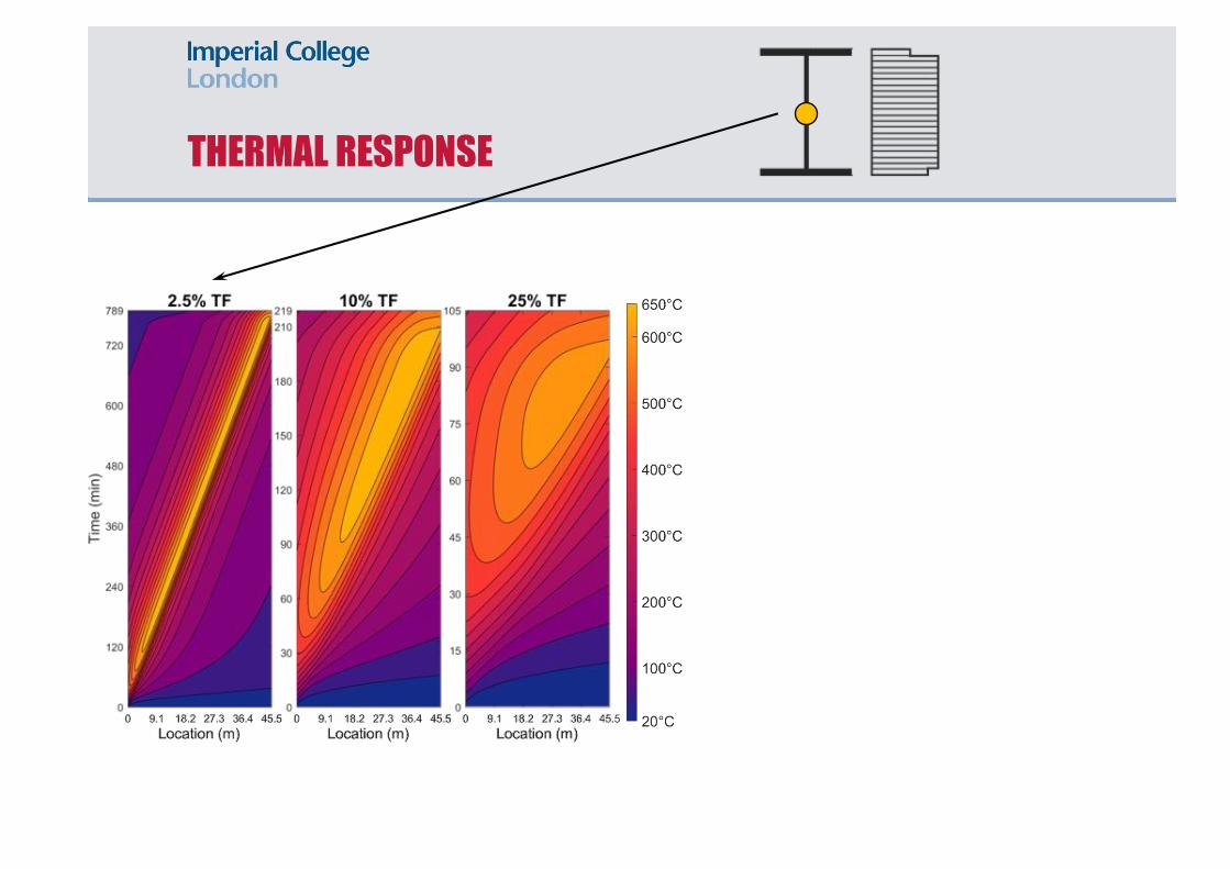
THERMAL RESPONSE

THERMAL RESPONSE
THERMAL RESPONSE

THERMAL RESPONSE

THERMAL RESPONSE

THERMAL RESPONSE
690°C680°C 635°C 370°C560°C 620°C

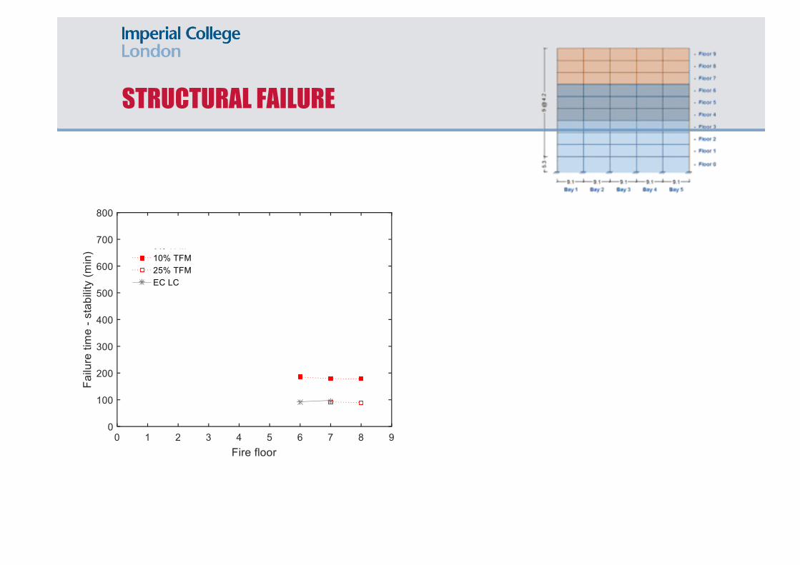
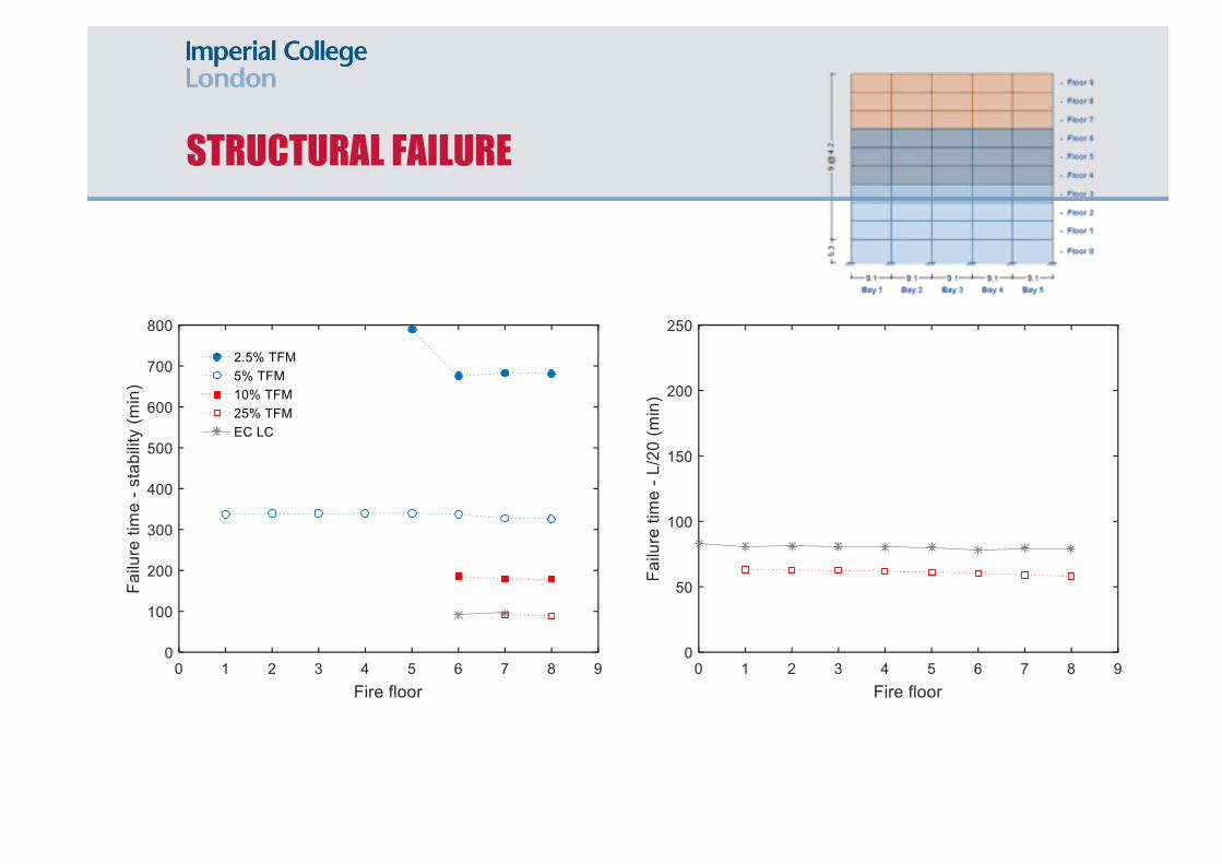
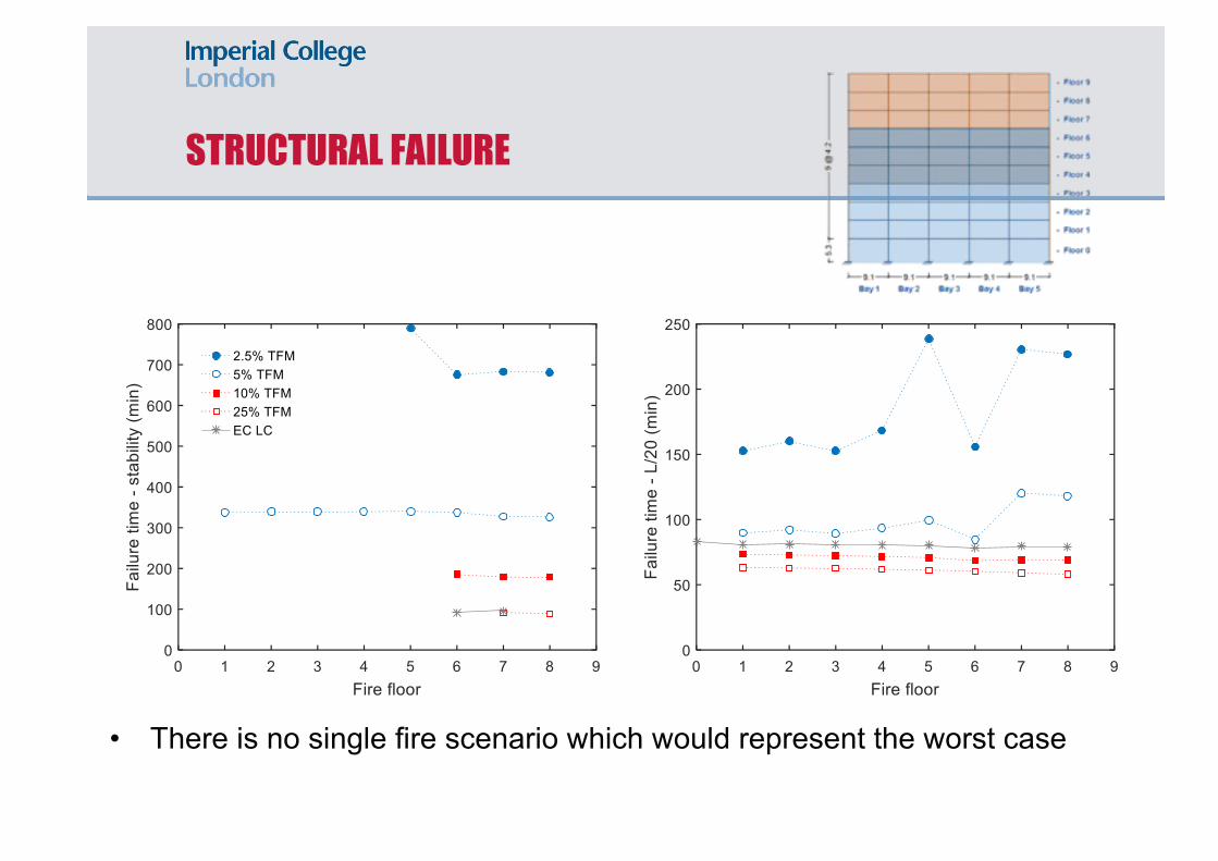
STRUCTURAL FAILURE

STRUCTURAL FAILURE

STRUCTURAL FAILURE
STRUCTURAL FAILURE

STRUCTURAL FAILURE

STRUCTURAL FAILURE

STRUCTURAL FAILURE
• There is no single fire scenario which would represent the worst case
• For different fire exposure failure occurs on different floors

STRUCTURAL FAILURE
• There is no single fire scenario which would represent the worst case
• For different fire exposure failure occurs on different floors
STRUCTURAL FAILURE
• There is no single fire scenario which would represent the worst case
• For different fire exposure failure occurs on different floors

STRUCTURAL FAILURE
• There is no single fire scenario which would represent the worst case
• For different fire exposure failure occurs on different floors

STRUCTURAL FAILURE
• There is no single fire scenario which would represent the worst case
• For different fire exposure failure occurs on different floors

STRUCTURAL FAILURE
• There is no single fire scenario which would represent the worst case
• For different fire exposure failure occurs on different floors
STRUCTURAL FAILURE
• There is no single fire scenario which would represent the worst case
• For different fire exposure failure occurs on different floors

STRUCTURAL FAILURE
• There is no single fire scenario which would represent the worst case
• For different fire exposure failure occurs on different floors

WEB TEMPERATURE AT FAILURE
• Stability criterion - 600–740°C• Deflection criterion - 450–700°C

WEB TEMPERATURE AT FAILURE
• Stability criterion - 600–740°C• Deflection criterion - 450–620°C

FAILURE TEMPERATURE

FAILURE TEMPERATURE
No
Does the element
fail during heating?
Yes
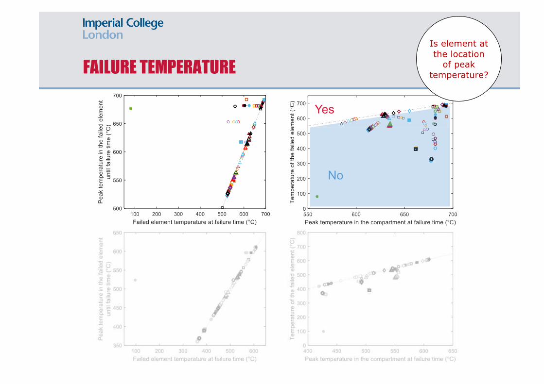
FAILURE TEMPERATURE
No
Is element at the location
of peak temperature?
Yes

FAILURE TEMPERATUREAv
erag
e Ba
y te
mpe
ratu
res

FAILURE TEMPERATURE
No
Aver
age
Bay
tem
pera
ture
s
Does the element
fail during heating?
Yes

FAILURE TEMPERATURE
Is element at the location
of peak temperature?
Aver
age
Bay
tem
pera
ture
s
No
Yes

TIME TO FAILURE
• No relationship between the time to reach the critical temperature in the compartment and the failure time.
• Good correlation between the times to reach the critical temperature in the failed element and times to failure.

TIME TO FAILURE
• No relationship between the time to reach the critical temperature in the compartment and the failure time.
• Good correlation between the times to reach the critical temperature in the failed element and times to failure.

TIME TO FAILURE
• No relationship between the time to reach the critical temperature in the compartment and the failure time.
• Best correlation between the times to reach the critical temperature in the failed element and times to failure.

CONCLUSIONS
• In large compartments, post-flashover fire cannot occur, but a travelling fire would develop
• Critical fire scenarios occur on the upper levels of the building.
• There is no single fire scenario which would represent the worst case.
• There is no relationship between the time to reach the critical temperature in the compartment and the failure time.

THANK YOU!
4 Pancras Square Battersea Power Plant
One New Ludgate
The Scalpel Two New Ludgate
S2 King’s Cross
NovaVictoria
View 58
Kings House
Barlett, UCL
39 iconic buildings
in UK
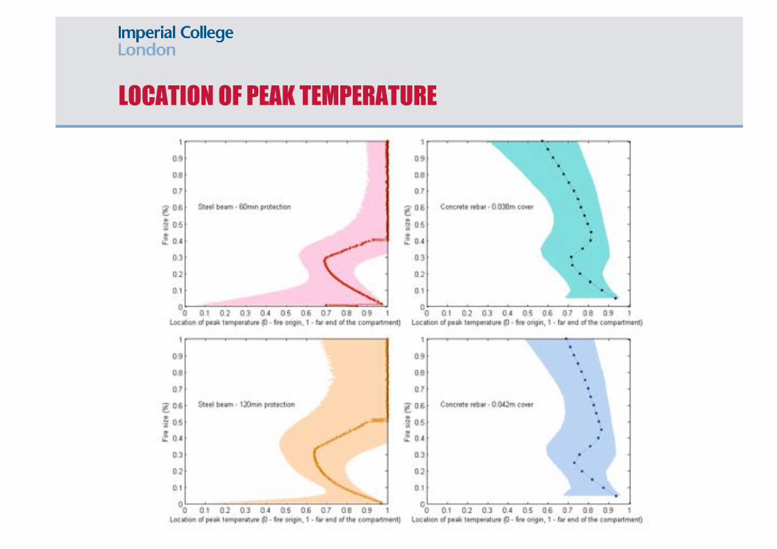
LOCATION OF PEAK TEMPERATURE

LOCATION OF PEAK TEMPERATURE
• Deflection criteria - no correlation with the location of the peak temperature.
• Stability - failure tends to occur towards the end of the fire path within the region where peak temperatures in the compartment develop.
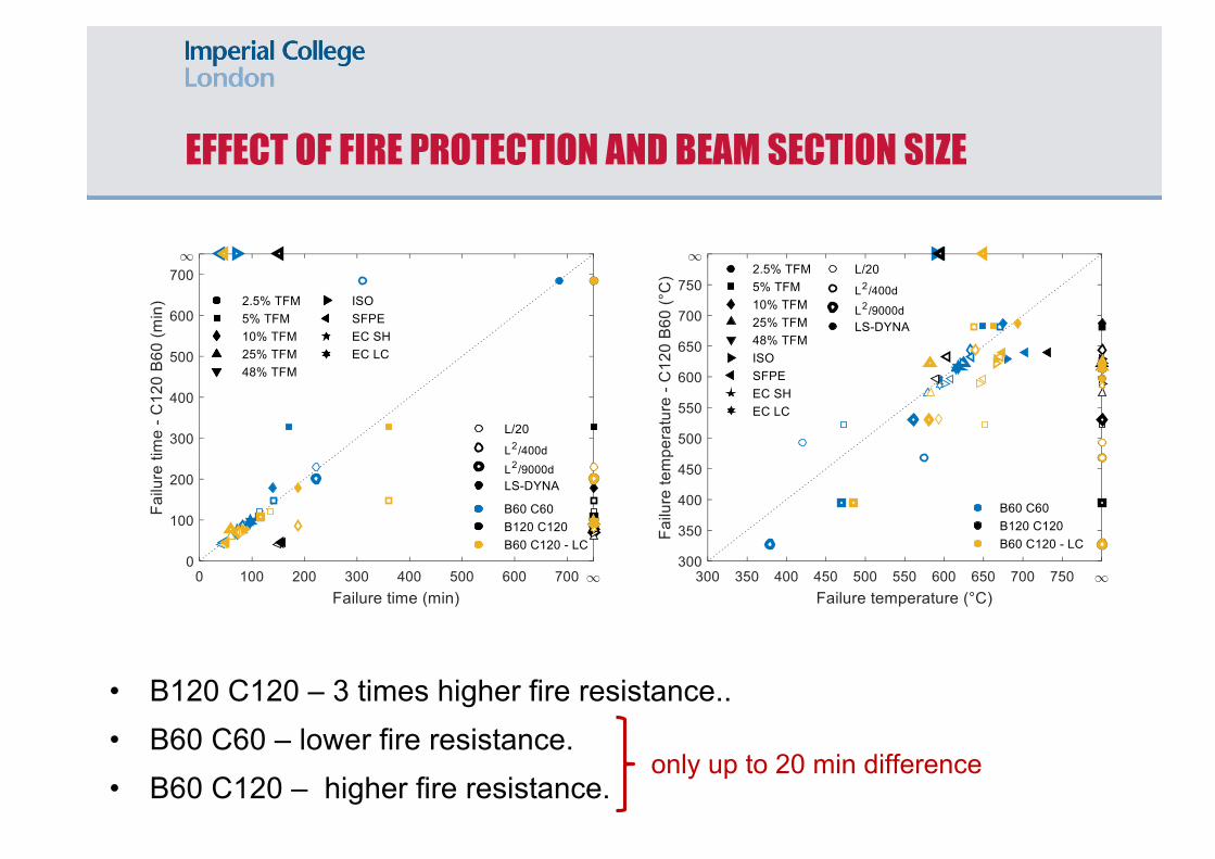
EFFECT OF FIRE PROTECTION AND BEAM SECTION SIZE
• B120 C120 – 3 times higher fire resistance..• B60 C60 – lower fire resistance.• B60 C120 – higher fire resistance.
only up to 20 min difference
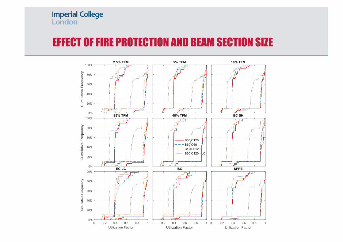
EFFECT OF FIRE PROTECTION AND BEAM SECTION SIZE
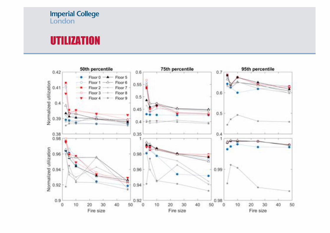
UTILIZATION