computational design of metal organic frameworks...
TRANSCRIPT
Computational Design of Metal−Organic Frameworks Based onStable Zirconium Building Units for Storage and Delivery of MethaneDiego A. Gomez-Gualdron,† Oleksii V. Gutov,‡ Vaiva Krungleviciute,§,∥ Bhaskarjyoti Borah,†
Joseph E. Mondloch,‡ Joseph T. Hupp,*,‡ Taner Yildirim,*,§,∥ Omar K. Farha,*,‡,⊥
and Randall Q. Snurr*,†
†Department of Chemical and Biological Engineering and ‡Department of Chemistry and International Institute for Nanotechnology,Northwestern University, 2145 Sheridan Road, Evanston, Illinois 60208, United States§NIST Center for Neutron Research, National Institute of Standards and Technology, Gaithersburg, Maryland 20899, United States∥Department of Materials Science and Engineering, University of Pennsylvania, Philadelphia, Pennsylvania 19104, United States⊥Department of Chemistry, Faculty of Science, King Abdulaziz University, Jeddah 22254, Saudi Arabia
*S Supporting Information
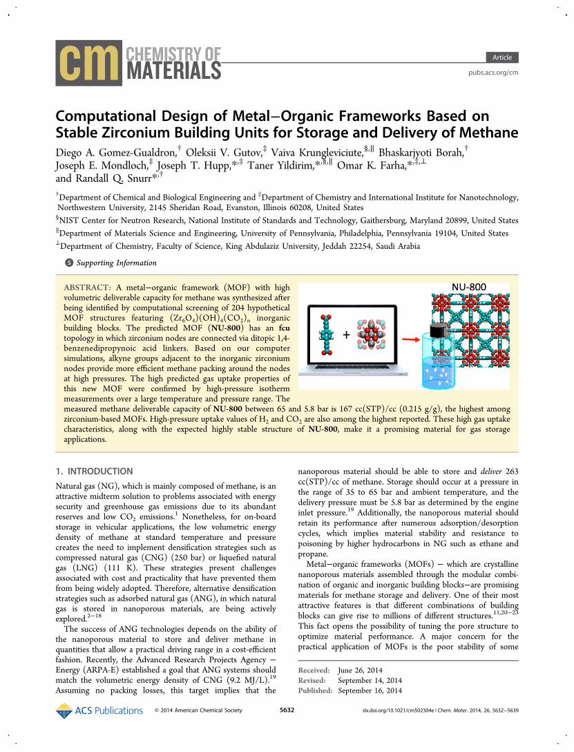
ABSTRACT: A metal−organic framework (MOF) with highvolumetric deliverable capacity for methane was synthesized afterbeing identified by computational screening of 204 hypotheticalMOF structures featuring (Zr6O4)(OH)4(CO2)n inorganicbuilding blocks. The predicted MOF (NU-800) has an fcutopology in which zirconium nodes are connected via ditopic 1,4-benzenedipropynoic acid linkers. Based on our computersimulations, alkyne groups adjacent to the inorganic zirconiumnodes provide more efficient methane packing around the nodesat high pressures. The high predicted gas uptake properties ofthis new MOF were confirmed by high-pressure isothermmeasurements over a large temperature and pressure range. Themeasured methane deliverable capacity of NU-800 between 65 and 5.8 bar is 167 cc(STP)/cc (0.215 g/g), the highest amongzirconium-based MOFs. High-pressure uptake values of H2 and CO2 are also among the highest reported. These high gas uptakecharacteristics, along with the expected highly stable structure of NU-800, make it a promising material for gas storageapplications.
1. INTRODUCTION
Natural gas (NG), which is mainly composed of methane, is anattractive midterm solution to problems associated with energysecurity and greenhouse gas emissions due to its abundantreserves and low CO2 emissions.1 Nonetheless, for on-boardstorage in vehicular applications, the low volumetric energydensity of methane at standard temperature and pressurecreates the need to implement densification strategies such ascompressed natural gas (CNG) (250 bar) or liquefied naturalgas (LNG) (111 K). These strategies present challengesassociated with cost and practicality that have prevented themfrom being widely adopted. Therefore, alternative densificationstrategies such as adsorbed natural gas (ANG), in which naturalgas is stored in nanoporous materials, are being activelyexplored.2−18
The success of ANG technologies depends on the ability ofthe nanoporous material to store and deliver methane inquantities that allow a practical driving range in a cost-efficientfashion. Recently, the Advanced Research Projects Agency −Energy (ARPA-E) established a goal that ANG systems shouldmatch the volumetric energy density of CNG (9.2 MJ/L).19
Assuming no packing losses, this target implies that the
nanoporous material should be able to store and deliver 263cc(STP)/cc of methane. Storage should occur at a pressure inthe range of 35 to 65 bar and ambient temperature, and thedelivery pressure must be 5.8 bar as determined by the engineinlet pressure.19 Additionally, the nanoporous material shouldretain its performance after numerous adsorption/desorptioncycles, which implies material stability and resistance topoisoning by higher hydrocarbons in NG such as ethane andpropane.Metal−organic frameworks (MOFs) − which are crystalline
nanoporous materials assembled through the modular combi-nation of organic and inorganic building blocks−are promisingmaterials for methane storage and delivery. One of their mostattractive features is that different combinations of buildingblocks can give rise to millions of different structures.11,20−23
This fact opens the possibility of tuning the pore structure tooptimize material performance. A major concern for thepractical application of MOFs is the poor stability of some
Received: June 26, 2014Revised: September 14, 2014Published: September 16, 2014
Article
pubs.acs.org/cm
© 2014 American Chemical Society 5632 dx.doi.org/10.1021/cm502304e | Chem. Mater. 2014, 26, 5632−5639

MOFs. However, MOFs with exceptional thermal, chemical,and hydrolytic stability,24−27 such as zirconium-based UiO-66,28 have now been synthesized. Furthermore, a variety ofMOFs having similar (Zr6O4)(OH)4(CO2)n inorganic buildingblocks have been found to be highly stable, suggesting that theirstability is linked to the presence of this type of buildingunit.23,29−37
To date, lack of hydrolytic and chemical stability (againstimpurities present in NG) has hindered the performance ofMOFs when subject to numerous adsorption/desorptioncycles. MOFs with the highest measured volumetric methanedeliverable capacity (storage at 65 bar and delivery at 5.8 bar)to date are MOF-51938 (203 cc(STP)/cc), UTSA-7639 (187cm3(STP/cc), MOF-517 (185 cc(STP)/cc), HKUST-115 (184cc(STP)/cc), and NU-12513 (174 cc(STP)/cc), which featureless stable inorganic building blocks such as Zn4O(CO2)6 orCu2(CO2)4. Improvement in the stability of, for instance,copper-based MOFs has been explored through the use ofbulky hydrophobic groups, which have been added postsyn-thesis via plasma treatment40 or prior to MOF synthesis as partof the organic building blocks.41 However, occupation of porevolume by bulky groups can be detrimental for storageapplications. Therefore, designing MOFs with inherent stabilityand high deliverable capacities is a very attractive goal.From an abstract perspective, creating new MOFs is as
simple as selecting appropriate organic and inorganic buildingunits and connecting them to form a three-dimensionalnetwork. However, experimentally, creating new MOFs canbe a time-consuming process that includes optimizing thesolvothermal reaction conditions for obtaining a crystallineproduct and optimizing the solvent evacuation procedure tofully “activate” the pores of the MOF. Molecular simulation canbe a valuable tool to accelerate the discovery of materials forapplications such as gas storage because it can provide valuableinsights to guide material design11,42−45 and can be used toscreen candidates and directly identify desirable candidates forsynthesis.11
Here we describe our efforts in computationally designingand screening 204 hypothetical MOFs featuring highly stable(Zr6O4)(OH)4(CO2)n inorganic building blocks, with the goalof identifying and synthesizing a zirconium based MOF withhigh volumetric deliverable capacity for methane. These effortsprovided valuable insights into structural features that improvemethane deliverable capacity and led to the synthesis,activation, and testing of the identified top zirconium-basedMOF in our screening: NU-800.
2. COMPUTATIONAL METHODSConstruction of Hypothetical MOFs. We used a reverse
topological approach,46 where the four topological nets shownin Figure 1 were used as “templates” for the construction ofzirconium-based hypothetical MOFs using the building blocksshown in Figure 2. Twelve ditopic organic building blocks werecombined with zirconium secondary building units (SBUs) toconstruct MOFs with a fcu topological net, which is thetopological net of UiO-66.28 The four central and nineperipheral building blocks were combined into 36 tetratopicbuilding blocks following the formula Y-4X, where Y refers tocentral building blocks and X to peripheral ones. These were inturn combined with zirconium SBUs to construct MOFs withftw, csq, and scu topological nets. ftw is the topological net ofMOF-52529 and NU-1100,33 while csq is the topological net ofMOF-54529 and NU-1000.32 The scu net was selected from
the RSCR database47 based on having the same connectivity ofthe zirconium SBUs as in the csq net. MOFs of csq and scutopological nets have 8-coordinated inorganic nodes, whereasthe fcu and ftw topological nets have 12-coordinated ones.Additionally, some ftw mixed-ligand and selected functionalizedMOFs were built (detailed description in the SI). Notice thatthe criterion for selecting topological nets was based onpreviously shown synthetic accessibility, for fcu, ftw, and csqnets, or their compatibility with experimentally observedzirconium SBU geometries (see Figure S3.1a), for the simpleedge-transitive scu net. This was done to increase theprobability for the hypothetical structures to be syntheticallyaccessible.fcu MOFs feature octahedral cages and smaller tetrahedral
ones, and ftw MOFs feature cubic cages and smaller octahedralones. On the other hand, csq MOFs have one-dimensionalhexagonal channels and smaller triangular ones, and scu MOFshave diamond channels. As noted by Bureekaew and Schmid,46
when the building blocks have lower symmetry than theircorresponding “vertex” in the network template, one canobserve isoreticular isomerism, which corresponds to structureswith the same topological net and same chemical formula, butdifferent arrangements of the building blocks. Here, one type ofisoreticular isomerism, which we refer to as type I, occurs forcsq and scu MOFs, because the somewhat rectangulartetratopic building blocks (with the exception of the perfectlysquare porphyrin-based building blocks) can be placed in twodifferent orientations in the network template, resulting inisoreticular isomeric MOF pairs that differ in their channel sizes
Figure 1. Four net topologies compatible with zirconium-basedMOFs.
Figure 2. Basic building blocks used to construct zirconium-basedhypothetical MOFs. The color-coded translucent dots indicateconnection points. In the names of the ditopic and peripheral buildingblocks, P indicates a phenyl ring and T indicates a triple bond.
Chemistry of Materials Article
dx.doi.org/10.1021/cm502304e | Chem. Mater. 2014, 26, 5632−56395633

(see illustration in Figure S3.3). Note that the tetratopicbuilding blocks were allowed to adopt their somewhatrectangular shape in mixed-ligand ftw MOFs but wereconstrained to a square shape in single-ligand ftw MOFs.Another type of isoreticular isomerism, which we refer to as
type II, occurs for csq, scu, fcu, and ftw MOFs when theorganic building blocks are isomers among themselves. Forinstance, the ditopic building blocks PTTP and TPPT areisomers, as are the tetratopic building blocks Py-4PTT, Py-4TPT, and Py-4TTP (Figure 3).
The type II isoreticular isomerism is interesting, because itresults in sets of MOFs with the same chemical formula thatfeature virtually equal unit cell sizes and, thus, virtually equalpore sizes and specific pore volumes. Remarkably, however, wefound that the adsorption properties can differ among thesetypes of isoreticular isomers, most notably for ftw and fcutopological nets, as we discuss in the next section. It is worthemphasizing that type II isoreticular isomerism can be readilycontrolled during synthesis through ligand selection. However,control over type I isoreticular isomerism (and sometimestopology) can be difficult to achieve, possibly requiring a carefultuning of synthesis conditions.After preliminary structures of the hypothetical MOFs were
obtained, they were subjected to structural optimization usingthe Universal force field48 to describe the energetics of thestructure (see details in the SI). We found that this procedurepredicts the experimental lattice constants of IRMOF-1,HKUST-1, UiO-66, and MOF-525 within 2.1%, 0.3%, 2.1%,and 0.62% accuracy, respectively. Furthermore, we havepreviously used this procedure to create preliminary MOFstructures to assess structural, textural, and adsorption proper-ties of materials of interest prior to their synthesis.33,49
Gas adsorption was calculated in these MOFs using grandcanonical Monte Carlo simulations using Universal force field48
parameters for MOF atoms, TraPPE force field parameters for
methane,50 nitrogen,51 and carbon dioxide,51 and the Levesquemodel for hydrogen.52 Lorentz−Berthelot mixing rules wereused to obtain the interaction parameters between MOF atomsand gas molecules. During the simulations, heats of adsorptionwere calculated using the fluctuation method.53 Surface areaswere calculated geometrically as the area of the surface createdby rolling a nitrogen-size probe over the MOF atoms.54 Voidfractions were calculated via Widom insertions of a heliumprobe, where the void fraction was equal to the average Widomfactor.55 Pore size distributions were calculated geometricallyusing the method of Gelb and Gubbins,56 where for a largenumber of random points in the pore volume, the largestsphere that can enclose each point without overlappingframework atoms is determined.
3. RESULTS
Property-Performance Relationships. We characterizedthe structural properties of the ∼200 hypothetical MOFs andsimulated their volumetric deliverable capacities for methanebetween 65 and 5.8 bar. The results revealed some relationshipswhich are important as guidelines for material design. In fact, asthese relationships were emerging from the screening (e.g., arelationship between deliverable capacity and the location oftriple bonds in the structures), we used them to guide theselection of new building blocks until the final set illustrated inFigure 2 was obtained. Figure 4a shows that the best volumetricdeliverable capacities are obtained with hypothetical MOFscontaining void fractions in the range of 0.78−0.85. It isapparent that MOFs with fcu and ftw topologies globallyexhibit better volumetric deliverable capacities than MOFs withcsq and scu topologies. Although the highest deliverablecapacity did not correspond to the MOF with the highestvolumetric surface area, in general these two variables arelinearly correlated as shown in Figure 4b. Moreover, the valuesof the volumetric surface area explain much of the difference inperformance among the four topologies explored here, as thesimilarity of Figures 4a and 4c suggests. These figures showthat, for the csq topology, upon variations in void fraction, thevolumetric surface area remained within the 1000−1450 m2/cm3 range, and the deliverable capacity remained within the106−142 cc(STP)/cc range.As mentioned above, some insights into the effect of MOF
structural features (i.e., location of triple-bonds) also emergedfrom our analysis. Notice that for a set of isomeric buildingblocks, such as the ones illustrated in Figure 3, the buildingblock can be terminated in a triple bond or in a phenyl group.
Figure 3. Example of a triad of isomeric tetratopic building blocks Y-4X, with Y = Py, and X = PTT, TPT, and TTP.
Figure 4. Performance-property and property-property relations for 200 hypothetical zirconium-based MOFs color-coded by topology. a)Deliverable capacity between 65 and 5.8 bar vs void fraction. b) Deliverable capacity between 65 and 5.8 bar vs volumetric surface area. c)Volumetric surface area vs void fraction. Pink: fcu topology; green: ftw topology; blue: scu topology; red: csq topology.
Chemistry of Materials Article
dx.doi.org/10.1021/cm502304e | Chem. Mater. 2014, 26, 5632−56395634

This posed an interesting design question: Does it matterwhich isomer is selected for synthesis. In previous work, someof us57 determined that incorporating triple bonds into theorganic building blocks is more efficient than incorporatingphenyl rings to increase the surface area, which as shown inFigure 4b correlates well with the performance of the MOF.Our simulations here suggest that the position of the triplebonds can also be important as apparent from comparing themethane deliverable capacities among MOFs of an isoreticular(type II) isomeric set (Figure 5a,b). Figure 5a shows this
comparison for triads of ftw isoreticular isomeric structuressuch as the one illustrated in Figure 3. Notice that the barsrepresenting structures with triple-bond termination (both setsof colored bars) are 10−20 cc(STP)/cc higher than the barsrepresenting the corresponding phenyl-terminated isomers(white bars).An analogous trend can be seen in Figure 5b for ftw and fcu
isoreticular isomeric pairs, where the bars for the structure withtriple-bond termination are 10−38 cc(STP)/cc higher thanthose for the corresponding isomer with phenyl ringtermination. For instance, the calculated deliverable capacityof TPPT is 38 cc(STP)/cc higher than that of PTTP and that ofPy-4PT is 15 cc(STP)/cc higher than that of Py-4TP. Weshould note that for the ftw topology, the position of the triplebond also helps boost the geometric surface areas (see moredetails in Figure S3.4). For instance, the hypothetical isomericftw MOFs TPE-4TTP, TPE-4TPT, and TPE-4PTT showgravimetric surface areas of 5950, 6300, and 6550 m2/g,respectively.The positive effect of the terminal triple bond can also be
extended to other MOFs. Indeed, seeking to design MOFs thatmay take advantage of this effect was a motivation to add theditopic TPT linker as an organic building block. Figure 5cshows the deliverable capacity comparison between fcu MOFs
based on linkers TPT, DPD, and PTP, which have similarlengths. The structure with the terminal triple bonds, TPT,outperforms the structure with the terminal phenyl rings, PTP.As a matter of fact, we found that the fcu MOF based on theTPT building block was predicted to have the highestdeliverable capacity between 65 and 5.8 bar among all of thehypothetical zirconium-based MOFs explored here. Thepredicted value is 197 cc(STP)/cc, which is among the bestvalues for predicted deliverable capacities at these operationconditions among all types of MOFs.44 This material was, thus,selected for synthesis, activation, and experimental testing.Before proceeding to synthesis, however, we tried to
understand why the “terminal” triple-bond configuration wasbeneficial for the cases illustrated in Figure 5. In Figure 6 we
show simulation-averaged methane density maps, in the lowpressure (1 bar) and high pressure (65 bar) regimes, comparingthe ftw MOFs Py-4TP and Py-4PT and the fcu MOFs TPT andPTP. Notice in the density maps at low pressure in Figure 6that the high-density red spots are located around thezirconium-based nodes. This observation agrees with thepreferred adsorption site of methane in UiO-66 determinedby neutron diffraction.58 In Figure 6a, at low pressure, thedifference between methane density around the nodes of ftwMOFs Py-4PT and Py-4TP is not significant, but at 65 bar thehigh density spots are larger and closer to the nodes of Py-4PTthan for Py-4TP. This indicates that at high pressure there is amore efficient packing of methane around the zirconium-basednodes in the triple-bond terminated Py-4PT. A similarobservation can be made in Figure 6b for the fcu MOFs PTPand TPT, where the high density spots at 65 bar are larger andextend closer to the nodes of TPT than for PTP. Thus, thehigher deliverable capacities of the structures with terminaltriple bonds are due to higher adsorption at the storagepressure.Figure 7 shows the simulated isotherms for the MOFs
discussed in Figure 6. Notice how the isotherms of Py-4PT andPy-4TP are similar at low pressure but start to diverge in favorof Py-4PT when the pressure increases. A similar trend isobserved when comparing TPT and PTP.
MOF Synthesis. Based on the simulation results, weproceeded to synthesize the zirconium-based fcu MOF basedon the TPT ligand, which features terminal triple bonds. We
Figure 5. Comparison of deliverable capacity between 65 and 5.8 baramong: a) triads of isoreticular isomeric ftw MOFs formed fromtetratopic building blocks Y-4X (where Y = TPE, Por, Py, and P). b)pairs of isoreticular isomeric MOFs formed from tetratopic buildingblocks Y-4X (ftw MOFs with Y = TPE, Por, Py, and P) and ditopicbuilding blocks TPPT and PTTP (fcu MOFs). c) fcu MOFs built withlinkers of similar lengths, including the MOF with the highestpredicted deliverable capacity among all MOFs studied here (TPT).
Figure 6. Simulation-averaged methane density maps at low (1 bar)and high (65 bar) pressure. The horizontal color bar indicates the scalefrom low density (black) to high density (orange). Regionsinaccessible to methane are not colored. a) Comparison betweenftw MOFs Py-4TP and Py-4PT. b) Comparison between fcu MOFsPTP and TPT. For clarity, the core of the zirconium-based node isdelineated in blue.
Chemistry of Materials Article
dx.doi.org/10.1021/cm502304e | Chem. Mater. 2014, 26, 5632−56395635

successfully synthesized the targeted MOF structure and referto it as NU-800. To the best of our knowledge, there are noother MOFs to date based on the terminal triple-bondconfiguration, with the exception of IRMOF-0,59 althoughthis MOF is based on a simple acetylene-dicarboxylic acidligand. We synthesized the organic ligand 3 (1,4-benzenedi-propynoic acid) from the commercially available 1,4-benzene-diacrylic acid (ligand 1) using a facile two-step procedureillustrated in Scheme 1.
We must note that application of synthesis protocols used forother zirconium-based MOFs did not result in a crystallineproduct when applied with ligand 3. Thus, screening of suitablesynthesis conditions was necessary. Based on the number ofconditions involving different solvents, modulators, reactantconcentrations, and reaction temperatures and times testeduntil conditions leading to a pure crystalline material werefound (see details in the SI), it is worth noting again that, in thesearch for the best materials for methane storage and delivery,computational efforts are able to drastically reduce syntheticefforts by suggesting the most promising structures.The best reaction conditions corresponded to a 120 h
solvothermal reaction of ligand 3 and ZrOCl2·H2O in DMFwith formic acid as a modulator at 70 °C. The generality of theprocedure was suggested by the successful synthesis of UiO-67(based on 4,4′-dibenzoic acid) and NU-801 (based on ligand1) also using the reaction conditions above.
There was good agreement between the PXRD pattern of thesynthesized material and the simulated pattern of the NU-800model (i.e., hypothetical fcu MOF TPT), confirming theformation of the targeted structure (Figure 8). Nevertheless,
the lattice constant of NU-800 was found to be 28.75 Å viaPawley refinement,60 indicating a 3.5% underprediction of thelattice constant by our structure generation procedure. With theexperimental value of the lattice constant, the NU-800 modelwas reoptimized, and the resulting structure was used tosimulate complete adsorption isotherms for various gases.Figure 8 also shows a view of the NU-800 structure,
illustrating the two cages characteristic of zirconium-basedMOFs with the fcu topological net. Accordingly, NU-800features large octahedral cages (indicated by purple spheres)formed by 12 linkers and six zirconium nodes, surrounded bysmall tetrahedral cages (indicated by blue spheres) formed bysix linkers and four zirconium nodes. The largest sphericalprobes that can fit in these pores are approximately 16.5 and 7.5Å, respectively, as shown by the pore size distribution shown asan inset in Figure 9.We were able to activate around 90% of the porosity of NU-
800 as indicated by a comparison of the simulated andmeasured nitrogen isotherms shown in Figure 9. SupercriticalCO2 activation
61 was necessary to get as close as possible to theideal surface area and pore volume, which is critical to achievethe best adsorption performance of a given MOF material.62
The measured BET surface area was ∼3150 m2/g, whichcorresponds to ∼89% of the simulated BET surface area of NU-800 (∼3560 m2/g), and similarly the activated pore volume was1.34 cc/g, which corresponds to ∼92% of the simulated porevolume (1.44 cc/g).
Figure 7. Simulated methane adsorption isotherms for the ftwisoreticular isomeric MOFs Py-4TP (empty triangles) and Py-4PT(filled triangles) and fcu MOFs PTP (empty circles) and TPT (filledcircles).
Scheme 1. Synthesis Procedure of Ligand 3 (TPT)
Figure 8. Top: Measured (purple) PXRD for NU-800 and simulatedPXRD for originally predicted (black) and reoptimized (blue) NU-800model structures. Bottom: View of the structure of the fcu MOF NU-800, with the purple spheres indicating the large octahedral cavities,and the blue spheres indicating the small tetrahedral cavities.
Chemistry of Materials Article
dx.doi.org/10.1021/cm502304e | Chem. Mater. 2014, 26, 5632−56395636

Gas Adsorption Measurements. In order to validate thepredicted adsorption characteristics of NU-800, we performedisotherm measurements over a large pressure and temperaturerange for methane. Additionally, we performed hydrogenadsorption measurements, which are also relevant for vehicularapplications. Figure 10 shows the comparison between the
simulated and measured isotherms. Overall there is goodagreement between the simulated and experimental results,with some discrepancies at high pressure partly due tosomewhat incomplete activation of the NU-800 sample. Themethane saturation loading at 125 K was measured as 34.3mmol/g, which corresponds to a pore volume of 1.37 cc/g, ingood agreement with the pore volume determined by nitrogenadsorption. A similar pore volume (1.30 cc/g) is alsodetermined by carbon dioxide adsorption at 220 K (FigureS7.1).The excess adsorption isotherm of hydrogen at 77 K (Figure
S7.3) shows a very shallow maximum at ∼35 bar, with a nearlyflat region between 20 and 65 bar. At 65 bar and 77 K, themeasured gravimetric hydrogen adsorption is 0.08 g/g. The
volumetric hydrogen adsorption capacity is 44.4 g/L, which isamong the highest reported at these conditions (i.e., 35 g/L forPCN-68,7 36 g/L for MOF-200,63 41 g/L for MOF-210,63 43g/L for NU-1100,33 47 g/L for NU-100,49 49 g/L for NU-11114 andMOF-17764). We note that among these MOFs onlyNU-1100 is based on highly stable zirconium building blocks.The high-pressure adsorption of carbon dioxide in NU-800 isalso significant, corresponding to 26 mmol/g at 35 bar. Theseresults clearly show that structurally stable zirconium-basedMOFs can compete with the copper paddle-wheel MOFs thathave large pore volumes and surface areas but are structurallyweaker.27
The room temperature methane uptake properties of NU-800 are shown in Figure 10 (and Figure 12) in gravimetric (andvolumetric) units. The methane deliverable capacity between65 and 5.8 bar was measured as 167 cc(STP)/cc, which is∼10% lower than the simulated value of 187 cc(STP)/cc. Weattribute this discrepancy to incomplete activation of oursample. With a different activation procedure it is quite possiblethat the methane uptake values of NU-800 could come closerto the simulated ones. We note, however, that even thisnonoptimized deliverable capacity of the zirconium-based MOFNU-800 is equal to or better than Ni-MOF-7414 (121cc(STP)/cc), PCN-1414 (149 cc(STP)/cc), and UTSA-2014
(162 cc(STP)/cc), and it is only 15% lower than the currentbest MOF-51938 (203 cc(STP)/cc) and 10% lower than theother top MOFs UTSA-76,39 HKUST-1,15 and MOF-517
(∼185 cc(STP)/cc). In addition, the measured NU-800gravimetric deliverable capacity of 0.216 g/g is higher thanthat of the MOFs mentioned above: MOF-519 (0.149 g/g),UTSA-76 (0.191 g/g), HKUST-1 (0.150 g/g), MOF-5 (0.213g/g), UTSA-20 (0.128 g/g), PCN-14 (0.129 g/g), and Ni-MOF-74 (0.075 g/g). It should be noted that MOF-519 hasbeen reported focusing on storage at higher pressures, with adeliverable capacity between 80 and 5.8 bar of 220 cc(STP)/cc.The simulated value for NU-800 at those operation conditionsis 203 cc(STP)/cc.In order to obtain additional insight about the guest−host
interactions in NU-800, we determined the heats of adsorption(Qst) for methane and hydrogen from the temperaturedependent experimental isotherms in Figure 10 using theClausius−Clapeyron equation (see the SI for details). Figure 11shows that the agreement between the simulated and measuredQst values is quite good for hydrogen and methane. Forhydrogen, the Qst initially remains roughly constant at ∼5 kJ/mol and then slowly decreases down to 3 kJ/mol with
Figure 9. Simulated (blue) and measured (purple) nitrogen isothermsat 77 K for NU-800. The inset shows the geometrically obtained poresize distribution.
Figure 10. Measured (blue lines with filled circles) and simulatedabsolute adsorption isotherms (dashed red lines) for methane andhydrogen at several temperatures.
Figure 11. Experimental (black lines from a spline and red lines from avirial fit) and simulated (scattered points) heats of adsorption.
Chemistry of Materials Article
dx.doi.org/10.1021/cm502304e | Chem. Mater. 2014, 26, 5632−56395637

increasing loading. For methane, the initial Qst is relatively lowwith values around 11 kJ/mol (simulated) and 12.5 kJ/mol(measured). A material with high methane deliverable capacityand a relatively low Qst may facilitate thermal management inANG on-board systems and may also make the material lessprone to “poisoning” by hydrocarbon impurities in natural gasduring adsorption/desorption cycles.Figure 12 illustrates the stability of NU-800 during
adsorption/desorption cycles. No evidence of sample degrada-
tion was found over a dozen cycles. The variation of theadsorption values at 65 bar and 298 K is within the 2%experimental error. Furthermore, we checked the pore volumeand surface area of the sample after a large number of isothermmeasurements were done with H2, CO2, and CH4 and did notsee any decrease in pore volume or surface area (Figure S6.5).
■ CONCLUSIONSWe have computationally constructed and screened over 200hypothetical MOFs based on highly stable zirconium buildingblocks. Our simulations suggest that alkyne groups adjacent tothe zirconium corner are more beneficial for methane storageand delivery than phenyl rings, because they allow an efficientpacking of methane around the zirconium corner at highpressure. It follows that this beneficial effect might be applicableto other MOFs where alkyne groups allow more efficientpacking around regions where methane/MOF interactions arestrong. Among the hypothetical zirconium-based materialsstudied, the MOF with the fcu topological net based on theditopic ligand 3 1,4-benzenedipropynoic acid was predicted tohave the best methane deliverable capacity. The MOF NU-800based on this ligand was successfully synthesized andcharacterized. The experimental structure was found to be ingood agreement with the preliminary NU-800 computermodel, as indicated by PXRD measurements. Upon super-critical CO2 activation, gas adsorption measurements confirmedthe predicted high capacity methane adsorption properties ofNU-800. In particular, the volumetric and gravimetric methanedeliverable capacities (between 65 and 5.8 bar) were measuredas 167 cc(STP)/cc (simulation: 187 cc(STP)/cc) and 0.215 g/g (simulation: 0.245 g/g), respectively. We determined thatNU-800 has a relatively low methane heat of adsorption (12.5kJ/mol measured and 11.6 kJ/mol simulated). Stability tests
over a large number of gas adsorption cycles indicated nosample degradation, consistent with the highly stable structuresof zirconium-based MOFs. Hydrogen adsorption in NU-800was also high with uptake values of 0.08 g/g and 44.4 g/L at 65bar and 77 K. Similarly the CO2 uptake at 35 bar was quite high(26 mmol/g). These promising gas uptake characteristics alongwith its expected superior stability make NU-800 a promisingmaterial for gas adsorption applications.
■ ASSOCIATED CONTENT*S Supporting InformationGeneral simulation, synthesis, and measurement methods.Simulation models. Details of MOF construction. Snapshotsof top hypothetical MOFs based on various metrics. Details ofNU-800 synthesis and activation. Nitrogen sorption and PXRDdata for NU-800, NU-801, and UiO-67. Detailed simulatedand measured CH4, H2, and CO2 adsorption isotherms for NU-800. Heats of adsorption. Excel file with tabulated screeningdata. Compressed file with 204 cif files for hypotheticalzirconium MOFs (including NU-800 molecular model). Thismaterial is available free of charge via the Internet at http://pubs.acs.org.
■ AUTHOR INFORMATIONCorresponding Authors*E-mail: [email protected].*E-mail: [email protected].*E-mail: [email protected].*E-mail: [email protected] ContributionsThe manuscript was written through contributions of allauthors. All authors have given approval to the final version ofthe manuscript. D.A.G.-G. and O.V.G. contributed equally.NotesThe authors declare the following competing financialinterest(s): Omar Farha, Joseph Hupp, and Randall Snurrhave a financial interest in the start-up company NuMatTechnologies, which is seeking to commercialize metal-organicframeworks.
■ ACKNOWLEDGMENTSThe Northwestern University team acknowledges that the workpresented herein was funded by the Advanced ResearchProjects Agency-Energy (ARPA-E), U.S. Department ofEnergy, under Award Number DE-AR0000248. T.Y. acknowl-edges support by the U.S. Department of Energy through BESGrant No. DE-FG02-08ER46522. The computations weremade possible by the high performance computing system,QUEST, at Northwestern University, and the National EnergyResearch Scientific Computing Center’s Carver Cluster.
■ REFERENCES(1) EIA U.S Crude Oil and Natural Gas Proved Reserves, 2011. http://www.eia.gov/naturalgas/crudeoilreserves/ (accessed Sept 13, 2014).(2) Wegrzyn, J.; Gurevich, M. Appl. Energy 1996, 55, 71.(3) Eddaoudi, M.; Kim, J.; Rosi, N.; Vodak, D.; Wachter, J.; O’Keeffe,M.; Yaghi, O. M. Science 2002, 295, 469.(4) Ma, S.; Sun, D.; Simmons, J. M.; Collier, C. D.; Yuan, D.; Zhou,H.-C. J. Am. Chem. Soc. 2007, 130, 1012.(5) Wu, H.; Zhou, W.; Yildirim, T. J. Am. Chem. Soc. 2009, 131, 4995.(6) Furukawa, H.; Yaghi, O. M. J. Am. Chem. Soc. 2009, 131, 8875.(7) Yuan, D.; Zhao, D.; Sun, D.; Zhou, H.-C. Angew. Chem., Int. Ed.2010, 49, 5357.
Figure 12. Experimental absolute methane adsorption isotherms forNU-800 at 298 K over a dozen adsorption/desorption cycles. Insetshows adsorption at 65 and 35 bar. The volumetric deliverable capacityof NU-800 between 65 and 5.8 bar is indicated by a vertical arrow.
Chemistry of Materials Article
dx.doi.org/10.1021/cm502304e | Chem. Mater. 2014, 26, 5632−56395638

(8) Klein, N.; Senkovska, I.; Baburin, I. A.; Grunker, R.; Stoeck, U.;Schlichtenmayer, M.; Streppel, B.; Mueller, U.; Leoni, S.; Hirscher, M.;Kaskel, S. Chem. − Eur. J. 2011, 17, 13007.(9) Mendoza-Cortes, J. L.; Pascal, T. A.; Goddard, W. A. J. Phys.Chem. A 2011, 115, 13852.(10) Stoeck, U.; Krause, S.; Bon, V.; Senkovska, I.; Kaskel, S. Chem.Commun. 2012, 48, 10841.(11) Wilmer, C. E.; Leaf, M.; Lee, C. Y.; Farha, O. K.; Hauser, B. G.;Hupp, J. T.; Snurr, R. Q. Nat. Chem. 2012, 4, 83.(12) Duan, X.; Yu, J.; Cai, J.; He, Y.; Wu, C.; Zhou, W.; Yildirim, T.;Zhang, Z.; Xiang, S.; O’Keeffe, M.; Chen, B.; Qian, G. Chem. Commun.2013, 49, 2043.(13) Wilmer, C. E.; Farha, O. K.; Yildirim, T.; Eryazici, I.;Krungleviciute, V.; Sarjeant, A. A.; Snurr, R. Q.; Hupp, J. T. EnergyEnviron. Sci. 2013, 6, 1158.(14) Peng, Y.; Srinivas, G.; Wilmer, C. E.; Eryazici, I.; Snurr, R. Q.;Hupp, J. T.; Yildirim, T.; Farha, O. K. Chem. Commun. 2013, 49, 2992.(15) Peng, Y.; Krungleviciute, V.; Eryazici, I.; Hupp, J. T.; Farha, O.K.; Yildirim, T. J. Am. Chem. Soc. 2013, 135, 11887.(16) He, Y.; Zhou, W.; Yildirim, T.; Chen, B. Energy Environ. Sci.2013, 6, 2735.(17) Mason, J. A.; Veenstra, M.; Long, J. R. Chem. Sci. 2014, 5, 32.(18) Barin, G.; Krungleviciute, V.; Gomez-Gualdron, D. A.; Sarjeant,A. A.; Snurr, R. Q.; Hupp, J. T.; Yildirim, T.; Farha, O. K. Chem. Mater.2014, 26, 1912.(19) ARPA-E Methane Opportunities for Vehicular Energy(MOVE),2012. http://arpa-e-foa.energy.gov(DE-FOA-000672) (accessed Sept13, 2014).(20) O’Keeffe, M.; Yaghi, O. M. Chem. Rev. 2011, 112, 675.(21) Martin, R. L.; Lin, L.-C.; Jariwala, K.; Smit, B.; Haranczyk, M. J.Phys. Chem. C 2013, 117, 12159.(22) Bon, V.; Senkovskyy, V.; Senkovska, I.; Kaskel, S. Chem.Commun. 2012, 48, 8407.(23) Feng, D.; Chung, W.-C.; Wei, Z.; Gu, Z.-Y.; Jiang, H.-L.; Chen,Y.-P.; Darensbourg, D. J.; Zhou, H.-C. J. Am. Chem. Soc. 2013, 135,17105.(24) Ferey, G.; Mellot-Draznieks, C.; Serre, C.; Millange, F.; Dutour,J.; Surble, S.; Margiolaki, I. Science 2005, 309, 2040.(25) Park, K. S.; Ni, Z.; Cote, A. P.; Choi, J. Y.; Huang, R.; Uribe-Romo, F. J.; Chae, H. K.; O’Keeffe, M.; Yaghi, O. M. Proc. Natl. Acad.Sci. U. S. A. 2006, 103, 10186.(26) Colombo, V.; Galli, S.; Choi, H. J.; Han, G. D.; Maspero, A.;Palmisano, G.; Masciocchi, N.; Long, J. R. Chem. Sci. 2011, 2, 1311.(27) Wu, H.; Yildirim, T.; Zhou, W. J. Phys. Chem. Lett. 2013, 4, 925.(28) Cavka, J. H.; Jakobsen, S.; Olsbye, U.; Guillou, N.; Lamberti, C.;Bordiga, S.; Lillerud, K. P. J. Am. Chem. Soc. 2008, 130, 13850.(29) Morris, W.; Volosskiy, B.; Demir, S.; Gandara, F.; McGrier, P.L.; Furukawa, H.; Cascio, D.; Stoddart, J. F.; Yaghi, O. M. Inorg. Chem.2012, 51, 6443.(30) DeCoste, J. B.; Peterson, G. W.; Schindler, B. J.; Killops, K. L.;Browe, M. A.; Mahle, J. J. J. Mater. Chem. A 2013, 1, 11922.(31) Zhang, W.; Huang, H.; Liu, D.; Yang, Q.; Xiao, Y.; Ma, Q.;Zhong, C. Microporous Mesoporous Mater. 2013, 171, 118.(32) Mondloch, J. E.; Bury, W.; Fairen-Jimenez, D.; Kwon, S.;DeMarco, E. J.; Weston, M. H.; Sarjeant, A. A.; Nguyen, S. T.; Stair, P.C.; Snurr, R. Q.; Farha, O. K.; Hupp, J. T. J. Am. Chem. Soc. 2013, 135,10294.(33) Gutov, O. V.; Bury, W.; Gomez-Gualdron, D. A.; Krungleviciute,V.; Fairen-Jimenez, D.; Sarjeant, A. A.; Snurr, R. Q.; Hupp, J. T.;Yildirim, T.; Farha, O. K. Chem. − Eur. J. 2014, DOI: 10.1002/chem.201402895.(34) Feng, D.; Gu, Z.-Y.; Li, J.-R.; Jiang, H.-L.; Wei, Z.; Zhou, H.-C.Angew. Chem., Int. Ed. 2012, 51, 10307.(35) Jiang, H.-L.; Feng, D.; Wang, K.; Gu, Z.-Y.; Wei, Z.; Chen, Y.-P.;Zhou, H.-C. J. Am. Chem. Soc. 2013, 135, 13934.(36) Mondloch, J. E.; Katz, M. J.; Planas, N.; Semrouni, D.; Gagliardi,L.; Hupp, J. T.; Farha, O. K. Chem. Commun. 2014, 50, 8944.(37) Nickerl, G.; Leistner, M.; Helten, S.; Bon, V.; Senkovska, I.;Kaskel, S. Inorg. Chem. Front. 2014, 1, 325.
(38) Gandara, F.; Furukawa, H.; Lee, S.; Yaghi, O. M. J. Am. Chem.Soc. 2014, 136, 5271.(39) Li, B.; Wen, H.-M.; Wang, H.; Wu, H.; Tyagi, M.; Yildirim, T.;Zhou, W.; Chen, B. J. Am. Chem. Soc. 2014, 136, 6207.(40) Decoste, J. B.; Peterson, G. W.; Smith, M. W.; Stone, C. A.;Willis, C. R. J. Am. Chem. Soc. 2012, 134, 1486.(41) Makal, T. A.; Wang, X.; Zhou, H.-C. Cryst. Growth Des. 2013,13, 4760.(42) Duren, T.; Sarkisov, L.; Yaghi, O. M.; Snurr, R. Q. Langmuir2004, 20, 2683.(43) Simon, C. M.; Kim, J.; Lin, L.-C.; Martin, R. L.; Haranczyk, M.;Smit, B. Phys. Chem. Chem. Phys. 2014, 16, 5499.(44) Gomez-Gualdron, D. A.; Wilmer, C. E.; Farha, O. K.; Hupp, J.T.; Snurr, R. Q. J. Phys. Chem. C 2014, 118, 6941.(45) Rana, M. K.; Koh, H. S.; Zuberi, H.; Siegel, D. J. J. Phys. Chem. C2014, 118, 2929.(46) Bureekaew, S.; Schmid, R. CrystEngComm 2013, 15, 1551.(47) O’Keeffe, M.; Peskov, M. A.; Ramsden, S. J.; Yaghi, O. M. Acc.Chem. Res. 2008, 41, 1782.(48) Rappe, A. K.; Casewit, C. J.; Colwell, K. S.; Goddard, W. A.;Skiff, W. M. J. Am. Chem. Soc. 1992, 114, 10024.(49) Farha, O. K.; Yazaydin, A. O.; Eryazici, I.; Malliakas, C. D.;Hauser, B. G.; Kanatzidis, M. G.; Nguyen, S. T.; Snurr, R. Q.; Hupp, J.T. Nat. Chem. 2010, 2, 944.(50) Martin, M. G.; Siepmann, J. I. J. Phys. Chem. B 1998, 102, 2569.(51) Potoff, J. J.; Siepmann, J. I. AIChE J. 2001, 47, 1676.(52) Levesque, D.; Gicquel, A.; Darkrim, F. L.; Kayiran, S. B. J. Phys.:Condens. Matter 2002, 14, 9285.(53) Nicholson, D.; Parsonage, N. G. Computer simulation and thestatistical mechanics of adsorption; Academic Press: London, 1982.(54) Bae, Y.-S.; Yazaydın, A. O.; Snurr, R. Q. Langmuir 2010, 26,5475.(55) Talu, O.; Myers, A. L. AIChE J. 2001, 47, 1160.(56) Gelb, L. D.; Gubbins, K. E. Langmuir 1998, 15, 305.(57) Farha, O. K.; Wilmer, C. E.; Eryazici, I.; Hauser, B. G.; Parilla, P.A.; O’Neill, K.; Sarjeant, A. A.; Nguyen, S. T.; Snurr, R. Q.; Hupp, J. T.J. Am. Chem. Soc. 2012, 134, 9860.(58) Wu, H.; Chua, Y. S.; Krungleviciute, V.; Tyagi, M.; Chen, P.;Yildirim, T.; Zhou, W. J. Am. Chem. Soc. 2013, 135, 10525.(59) Tranchemontagne, D. J.; Hunt, J. R.; Yaghi, O. M. Tetrahedron2008, 64, 8553.(60) Pawley, G. J. Appl. Crystallogr. 1981, 14, 357.(61) Nelson, A. P.; Farha, O. K.; Mulfort, K. L.; Hupp, J. T. J. Am.Chem. Soc. 2008, 131, 458.(62) Chowdhury, P.; Bikkina, C.; Meister, D.; Dreisbach, F.; Gumma,S. Microporous Mesoporous Mater. 2009, 117, 406.(63) Furukawa, H.; Ko, N.; Go, Y. B.; Aratani, N.; Choi, S. B.; Choi,E.; Yazaydin, A. O.; Snurr, R. Q.; O’Keeffe, M.; Kim, J.; Yaghi, O. M.Science 2010, 329, 424.(64) Furukawa, H.; Miller, M. A.; Yaghi, O. M. J. Mater. Chem. 2007,17, 3197.
Chemistry of Materials Article
dx.doi.org/10.1021/cm502304e | Chem. Mater. 2014, 26, 5632−56395639