computational parametric investigation on single … · computational parametric investigation on...
TRANSCRIPT

47RRJET | Volume 7 | Issue 1 | March, 2018
Research & Reviews: Journal of Engineering and Technology e-ISSN:2319-9873
Computational Parametric Investigation on Single Cylinder Spark Ignition Engine using Blends of Gasoline-Ethanol-H2O Micro Emulsions Under Varying Percentage
LoadUfaith Hussain Qadri* and M Marouf Wani
Department of Mechanical Engineering, National Institute of Technology, Hazratbal, Srinagar, Kashmir, India
Research Article
INTRODUCTIONIt is well known that fossil fuel reserves are diminishing at an alarming rate, so the need is to work on various alternative
technologies in order to overcome energy crises. Various alternative fuels are already in use and have been commercialized in many countries including India. The most commonly used alternative fuel is Ethanol, used as blended fuel in conventional gasoline. Ethanol is one of the alternative fuels which are obtained from sugar cane, starch (corn, wheat, grains). Ethanol is classified into two groups: "First-generation" or conventional bio fuels are made from vegetable oil, starch, or sugar. Correspondingly second generation ethanol is produced from biomass (straw, wood, and grasses) with scientific knowledge which is under technical description [1]. Micro emulsions are visually transparent and thermodynamically reliable diffusion systems having three ingredients a polar phase and a non-polar phase (water and Oil respectively) and a relevant surfactant usually in blending with a co-surfactant such as alcohol [2,3]. Micro emulsion is formed when oil droplets in O/W systems or water droplets in W/O systems are small (Table 1).
Table 1. Characteristics of micro-emulsions.
Parameter Micro-emulsionFormation SpontaneousStable ThermodynamicallyDroplet size(μm) 0.01-0.10Appearance TransparentSurface area High(200)Interfacial Tension Ultra low
Received date: 16/10/2017
Accepted date: 09/11/2017
Published date: 30/01/2018
*For Correspondence
Ufaith Hussain Qadri, Faculty of Engineering, Department of Mechanical Engineering, National Institute of Technology, Hazratbal, Srinagar, Kashmir, India, Tel: 0194 242 2032.
E-mail: [email protected]
Keywords: AVL, Boost, Combustion, Emissions, Micro-emulsion, Performance
ABSTRACT
In reply to detrimental environmental conditions from batch depletion of gasoline fuels as well as global petroleum reserves being limited, many countries initiate to find solution for meeting the future demand of fuel used for transport. Ethanol-gasoline fuel blends have already been commercialized in many countries including India. Gasoline-alcohol-H2O based micro-emulsion fuel substitute a new and economically a better option. Micro-emulsions are thermodynamically stable so it has received lot of consideration because of physico-chemical behaviour, and diverse applications. Lot of work has already been done in the areas of micro emulsion gels and preparation of vitamin E emulsions. But preparing, characterizing, and testing of micro emulsion fuels composed of Gasoline-H2O and especially of ethanol-blended gasoline and H2O,used in spark ignition engines remain virtually unexplored. In this work we have prepared blends of various micro emulsion compositions of gasoline-ethanol and water in definite proportions, and tested the performance and emission characteristics in AVL Boost software in order to see if micro emulsion fuel is efficient in terms of performance and exhaust emissions. It was observed that micro emulsion fuel is more efficient as power increased and exhaust emission were reduced.

48RRJET | Volume 7 | Issue 1 | March, 2018
Research & Reviews: Journal of Engineering and Technology e-ISSN:2319-9873
system type W/O,O/W, and bicontinuousCo-surfactant type Short Chain Alcohol
Micro emulsions and micelles provide an additional method for changing fuel compositions to accommodate the addition of alcohols, industrial by products, and vegetable or tree oil free fatty acids. Because of the small amount of water or methanol normally included as a dispersed phase in diesel fuel, it is possible to include inorganic salts, such as ammonium nitrate, which are good, inexpensive cetane enhancers [4]. These materials are also sparingly soluble in micellar fuels in which a polar alcohol forms the continuous phase. Hydrocarbon fuels like diesel oil, gasoline, fuel oil are derived from fossil fuels like petroleum. The detrimental effects of the toxic waste such as carbon monoxide, nitrogen oxide, hydrocarbon, Sulphur products and soot throw out by combustion of fossil fuels on the environment and depleting petroleum reserves have driven the need for exploring alternative fuel sources to meet the future energy demand. There is also a growing need for fuels, which promise major improvements in efficiency, emissions and cost effectiveness. Renewable biomass fuels have been gaining increasing acceptance globally because of far less emissions compared to fossil fuels. Canadian Patent CN 1441035 discloses the production of ethanol gasoline, which involves screening, cleaning, stamping, fermentation, distillation of rotten sugarcane, rotten apple, sawdust and crop straw materials to produce ethanol followed by mixing the industrial ethanol so produced with, denaturing agent such as isopropanol and gasoline with stirring. The patent claims rich raw material source and low cost. Hydrous alcohol and gasoline have mutual solubility problems, which limits the minimum concentration of alcohol in the blend. On the other hand, higher alcohol concentration is unacceptable to the existing engines and thus requires modification to the engine. Ethanol gasoline fuel mixture straightly defines vehicular pollutions and the sustainable ethanol blend in the gasoline can result in net reduction of emissions like carbon monoxide. Researchers have attempted to dissolve water –soluble alcohols like methanol and ethanol in hydrocarbon fuels to reduce petroleum consumption. In the Brazil, Sweden, and United states there is at present on a large scale use of ethanol fuel and gasoline ethanol fuel blends. However, the amount of ethanol used is rather on higher side to permit the existing engines to use the same without any modifications [4]. Japanese patent 2-140568 introduce a fuel blend contained reformed butanol, methanol, and gasoline at a blending ratio of approximately 1:2:2 with pigment and antirust as additives. The composition because of elevated combustion temperature results in the rise of temperature, which is detrimental to structural parts of the engine, and is apt to cause knocking.
PHYSICAL AND CHEMICAL PROPERTIES OF MICROEMULSIONSMicro emulsions and micellar fluids are thermodynamically stable liquid systems in which aggregates of one phase are
distributed throughout a second continuous and immiscible phase. They may appear transparent because the aggregates are smaller than the wavelength of visible light. At the extremely small sizes of the aggregates 1 to 100 nanometers Brownian motion is sufficient to make the aggregates stable in solution. Both micelles and micro emulsions are stable within definable ranges of chemical composition, temperature, and pressure, although current theory suggests that the dispersed phase aggregates may transition through a variety of shapes and sizes. Polar heads turned outward into a polar continuous phase generally characterize micelles. If hydrocarbon is solubilized by incorporation into the micelles, they are sometimes called “swollen micelles” and the system, an oil-in-water, or O/W micro emulsion, to distinguish it from a W/O micro emulsion, in which the hydrocarbon phase is continuous [2].
DROPLETS PHASESO/W Micro Emulsion
In the case of micro emulsions oil in water (O/W), droplets are formed with the surfactants head- groups oriented towards the continuous water phase and the non-polar tails grouped inside the hydrophobic core of the aggregate [5].
W/O Micro Emulsion
In oil-rich micro emulsions, water is solubilized as small droplets surrounded by a membrane of surfactant and co surfactant molecules. At high water concentration, micro emulsions consist of small oil droplets dispersed in water, whereas at lower water concentrations the situation is reversed and the system consists of water droplets dispersed in oil. In each phase the oil and water are separated by surfactant-rich film [5].
Heat Transfer Model
Heat transfer in engines during exchange of gas greatly affects the volumetric efficiencies specifically at lower engine speeds [6]. Based on AVL experience and measurements conducted at Graz Technical University, the heat transfer model namely woschni model has been modified to take this effect [7]. The heat transfer coefficient is calculated from the following equation.
( ){ }0.820.2 0.8[ ,0.013 ^ 0.53 4 / ]Max woschini d P T c din d vin−∝= ∝ − (1)
α = heat transfer coefficients [J/K/M2]
C4 = 14.0

49RRJET | Volume 7 | Issue 1 | March, 2018
Research & Reviews: Journal of Engineering and Technology e-ISSN:2319-9873
d = bore [m]
p = pressure [Pa]
T = temperature [K]
din = Pipe diameter connected to intake port [m]
vin = intake port velocity [m/s]
In the woschni heat transfer model the diameter of intake port is very significant and they need to be specified very accurately over the whole Port length [7].
Combustion Model
In this simulation set up we have used the vibe 2 zone model for analysis of combustion of micro emulsion fuel [7]. The hydrocarbon fuel which is used in engines is not that simple like methane fuel, but it consists of Isooctane and man additives. The reaction between oxygen and isooctane is shown below [8]:
C8H18 + 12.5O2 = 8CO2 + 9H2O (1)
Both nitrogen and oxygen are found in atmosphere with oxygen composition 21% and nitrogen 78% by mole. The combustion of isooctane with air is
C8H18 + 12.5O2 + 12.5(3.76) N2 = 8CO2 + 9H2O + 12.5(3.76) N2 (2)
The combustion process for ethanol is
C2H5OH + 3O2 = 2CO2 + 3H2O (3)
Ethanol described by C2H5OH mixes with oxygen with six atoms which is represented as 3O2. As the reaction initiates after adding energy which is in the form of Spark or heat 2CO2 and 3H2O are formed. In this reaction there is release of energy as well.
Simulation Setup
SB1
SB2PL1 PL2 PL3
C1
R1R2
R3
I1
MP1MP2MP3
MP4
MP5
MP6
MP7
CL11234
5
6
7
8 9 10
11
Figure 1. Layout of single cylinder gasoline SI engine model made in AVL boost simulation software for checking the performance and exhaust emission under constant speed and varying percentage loads using various micro emulsion fuels.
The one-Dimensional Simulation model of engine is made by software AVL Boost, and after developing the model it is made to investigate the engine performance which works on micro emulsion blends of anhydrous ethanol, H2O, and gasoline in varying proportions. The simulation software model was used for performing the simulations on a single cylinder Spark ignition engine. This Engine model has been calibrated by AVL Boost and the Layout is shown in Figure 1, and specifications of engine are shown in Table 2. The various elements of AVL Software enables user to develop a model of one- Dimensional test engine bench setup by using the Pre-defined elements which are present in the toolbox of software. All these elements are joined by various connectors for making the engine model complete by using pipelines [9].
In Figure 1, engine is denoted by E1 and C1 represent the single cylinder of Engine. Mp1 to Mp7 denote measuring points. Pl1 to Pl3 denotedplenum. SB1 and SB2 are system boundary and the flow pipes are from 1 to 10.CL1 represents cleaner, R1 to R3 are restrictions.

50RRJET | Volume 7 | Issue 1 | March, 2018
Research & Reviews: Journal of Engineering and Technology e-ISSN:2319-9873
Table 2. Engine specifications.
Criteria DescriptionMake Briggs and StrattonType Air cooled 4 stroke OHV Gasoline
Displacement 206 ccCompression ratio 9Bore and Stroke 65.09 × 61.91
Maximum HP 6.5Cooling System Air CooledIgnition System Magnetron Electronic
Compositions Used For Micro Emulsions
The alcohol used may be having carbon atoms up to 10. The alcohol used preferably be ethanol more preferably be industrial ethanol when the fuel is to be used at normal ambient temperature and iso-amyl alcohol, 1-octanol, 1-decanol in isolation or in combination when the fuel is to be used at low temperatures still more preferably in combination with ethanol. The following description further illustrates the underlying principles that help in achieving the objectives. Addition of water helps in better combustion, lesser pollution and lesser emission. One of the direct advantages of the presence of water in a stable micro emulsion is successful reduction of soot formation. As soon as the micro emulsion reaches the combustion space, the water domains evaporate instantly with such energy that all particles around it are broken into fragments. More specifically, within the space covered by a water domain, the sudden rise in water temperature cause a sudden rise of pressure and that bursts the drop. Thus presence of additive which is water formed micro emulsion fuel improves fuel economy in terms of price and miles/volume of the fuel. It reduces the excess air requirements. Further, ethanol contains oxygen. So blending hydrous ethanol with gasoline results in more complete fuel combustion. Another attractive quality of micro emulsion fuel is an increased octane number of gasoline, which helps in better combustion [4].
Though the micro emulsion is possible without addition of surfactant, it fails to remain stable at low temperatures and also leads to increase in the concentration of alcohol. Table 3 accompanying this specification illustrates the possible composition of stable fuel.
Table 3. Compositions used without surfactant.
Gasoline percentage (%) Water (%) Ethanol Anhydrous (%)62.5 6.25 31.2565.2 2.17 32.6
65.5 1.63 32.7
MATHEMATICAL MODELMathematical models for spark–ignition engines can be divided into two main groups’ thermodynamic and dimensional
models. Thermodynamic models can in turn be classified in two subgroups single and multi-zone models whereas dimensional models can be divided into one and multi-dimensional models. Single zone models can also be used as predictive tools if the mass burning rate is specified. The mass burning rate depends on the engine geometry, equivalence ratio, ignition angle, combustion duration, residual mass etc. Therefore tuning may be required to presume the diagrams for pressure in various engines which operates under different conditions [10].
Single – Zone Models
In this model we assume pressure, temperature, and composition of cylinder charge is assumed to be uniform. In this model the state of cylinder charge for average properties do not classify between burnt and un-burnt gasses, and suppose that there is homogenous cylinder charge. Multi zone models permit a more accurate treatment of the thermodynamic properties of the cylinder mixture; the burnt and un-burnt gasses are considered as independent thermodynamic systems whose composition and state are uniform. However the geometry of each zone must be tracked in order to calculate the heat transfer and composition of the burnt and un-burnt gasses are considered as independent thermodynamic systems whose composition and state are uniform [11]. In single zone model combustion is considered as heat addition process and the charge chamber is regarded as a simple fluid. For open system the first law of thermodynamics can be written as:
( )
0
0 T
mev
T
d dV dQp mi hi e e C dTd d dθ θ θ
= − − + = +∑ ∫ (1)
Where m, p, and T are mass, pressure, and temperature of the cylinder charge, respectively is the mixture specific internal

51RRJET | Volume 7 | Issue 1 | March, 2018
Research & Reviews: Journal of Engineering and Technology e-ISSN:2319-9873
energy is the combustion chamber volume; dQ/dθ represents the heat losses; hi is specific enthalpy which flows into the cylinder having mass flow rate equal to Ai;T0 is a reference temperature;𝑒0 is the internal energy of formation at the reference temperature T0; and θ is the crank shaft angle [12].
In the absence of injection and flows into crevices, dm/dθ = 0.In premixed charge engines, there are flows into and out of crevices (i.e., volumes between the Cylinder wall, piston rings and piston and the spark plug threads). The crevices can be modeled as a single volume at the cylinder pressure or as a series of volumes, connected by restrictions to simulate the piston ring- cylinder wall region and blow by. Equation (1) can be written as:
( )CH CRv
dQ dmdT dV dQmC p h ed d d d dθ θ θ θ θ
= + + + − (2)
Where dQCH /dθ represent the heat released by combustion, dmCR/dθ represents the mass flow rate into crevices, and h is the specific enthalpy. Conservation of mass applied to the combustion chamber yields:
CRdmdmd dθ θ
=− (3)
When the cylinder pressure is high and the value of h corresponds to that in the combustion chamber:
h = e + PV/m (4)
However, during the expansion stroke, dmcr/dθ< 0 and the value of h is that of the gasses contained in the crevices. If the crevice volume and temperature are assumed constant and the crevice pressure is equal to that of the cylinder charge, the mass flow rate into the crevices can be written as:
/ CR
CRdm dp dVd RTw
θθ
= (5)
Where the crevice temperature was set equal to the temperture of the cylinder wall Tw and VCR is the crevice volume. Equation (5) can be substituted into equation (2) and (3) to obtain an equation for the heat released by combustion once the heat transfer losses dQ/dθ are specified. Heat transfer correlations once the heat transfer losses dQ/dθ is specified [11].
RESULTS AND DISCUSSIONPower And Torque
Figure 2. (a) Plot between power and percentage load, at varying micro-emulsion compositions (b) Plot between torque and percentage load.
In Figure 2a plot shows the power with various blends of micro emulsion fuels, under varying Loads. The graph clearly shows the variation of power with increase in the percentage of ethanol and H2O concentration in the conventional gasoline fuel. There is slight variation in power with concentration of water as 6.25% as additive in fuel, since power is increasing for almost for all the micro emulsion fuels, so in terms of performance micro emulsion fuel play an important role in increasing the power of an SI engine at increasing Loads. Figure 2b defines the role of Torque with respect to increase in percentage Load. The plot shows variation of torque with various micro emulsion fuels, Torque is increasing for 2.17% water as additive in gasoline-ethanol blends. So the graph clearly defines that by keeping the concentration of water less, the power and torque is increasing [13].

52RRJET | Volume 7 | Issue 1 | March, 2018
Research & Reviews: Journal of Engineering and Technology e-ISSN:2319-9873
Bmep And Bsfc
Figure 3. (a) Shows the plot between Bmep and load under varying compositions of micro emulsion fuel. (b) Shows the plot between Bsfc and percentage load.
In Figure 3a there is comparison of various micro emulsion fuels for varying loads, in order to see the effect of Bmep. In the graph it is explaining the increase in Bmep after increasing loads on engine. So pressure increases for almost for all the micro emulsion fuels. So micro emulsion fuel is efficient in terms of performance, as work output is increasing for all the compositions of micro emulsions. In Figure 3b, the Bsfc continuously decreases up to the load of 60%, for all the micro emulsion fuels in varying proportions. At start of the combustion the mixture is rich so Bsfc is more for all the micro emulsion fuels, but as the load increases the mixture turns more towards the leaner side and the air consumption increases, and fuel is going less to the engine, so combustion completes and Bsfc also decreases, so Bsfc decreases after increasing loads, which is actually the increase in consumption of air. So we concluded that at leaner side of the mixture fuel is more efficient in terms of performance and exhaust emissions.
Pressure v/s Crank Angle
Figure 4. Shows the plot between pressure and crank angle under varying micro emulsion fuels.
In Figure 4 the plot between pressure and crank angle shows how pressure increases for all the micro emulsion fuels. The pressure is almost same for all the micro emulsion fuels, as peak in pressure occurs at the start of compression stroke. So pressure is more at the start of combustion. Therefore pressure increases up to 20 bar [13]. Both pressure and temperature increases at higher compression ratio and also decreases the concentration of residual gases. With increase in load the cycle pressure increases and the flame speed also increases.
53RRJET | Volume 7 | Issue 1 | March, 2018
Research & Reviews: Journal of Engineering and Technology e-ISSN:2319-9873
Exhaust Temperature
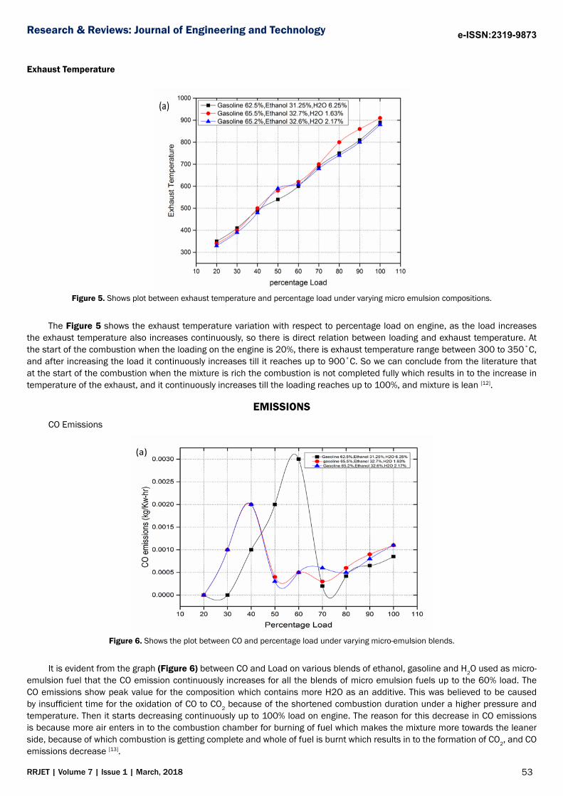
Figure 5. Shows plot between exhaust temperature and percentage load under varying micro emulsion compositions.
The Figure 5 shows the exhaust temperature variation with respect to percentage load on engine, as the load increases the exhaust temperature also increases continuously, so there is direct relation between loading and exhaust temperature. At the start of the combustion when the loading on the engine is 20%, there is exhaust temperature range between 300 to 350˚C, and after increasing the load it continuously increases till it reaches up to 900˚C. So we can conclude from the literature that at the start of the combustion when the mixture is rich the combustion is not completed fully which results in to the increase in temperature of the exhaust, and it continuously increases till the loading reaches up to 100%, and mixture is lean [12].
EMISSIONSCO Emissions
Figure 6. Shows the plot between CO and percentage load under varying micro-emulsion blends.
It is evident from the graph (Figure 6) between CO and Load on various blends of ethanol, gasoline and H2O used as micro-emulsion fuel that the CO emission continuously increases for all the blends of micro emulsion fuels up to the 60% load. The CO emissions show peak value for the composition which contains more H2O as an additive. This was believed to be caused by insufficient time for the oxidation of CO to CO2 because of the shortened combustion duration under a higher pressure and temperature. Then it starts decreasing continuously up to 100% load on engine. The reason for this decrease in CO emissions is because more air enters in to the combustion chamber for burning of fuel which makes the mixture more towards the leaner side, because of which combustion is getting complete and whole of fuel is burnt which results in to the formation of CO2, and CO emissions decrease [13].

54RRJET | Volume 7 | Issue 1 | March, 2018
Research & Reviews: Journal of Engineering and Technology e-ISSN:2319-9873
HC Emissions
Figure 7. Shows the plot between HC and percentage load under varying micro emulsion blends.
Similarly in case of HC emissions the emissions are at higher side at lower loads, as shown in Figure 7, and decreasing continuously after increasing loads on engine, this happens because of incomplete combustion at the start of engine loads. The reason behind this higher HC emission up to 60% load is because the mixture is rich, the air is going less at lower loads, and fuel is not burning fully so HC emissions are going up, while as at increasing loads the mixture starts going from rich to leaner side, and fuel consumption is going at lower side, and air is going more into the engine, so combustion is getting completed fully resulting into the formation of less HC emissions, and it continuously decreases at increasing loads [13].
CONCLUSION In this study, we tried to investigate various micro emulsion blends by using (gasoline, water and ethanol) as co surfactant
for the micro emulsion formation. For this purpose effects of change in brake power, torque, Bsfc on both performance and emission characteristics of engine having different micro emulsion use on engine operated with single cylinder SI engine fitted to a petrol generator were investigated. All the simulations were performed on single cylinder SI engine at varying load and engine speed was kept constant. The change in Brake power, Torque, Bmep, Bsfc, and emissions from exhaust were investigated. In this study the results obtained are described below.
• While power showed continuously increasing for all the micro emulsion blends, so in terms of power production the fuel seems very efficient.
• In Torque we saw some variation for all the micro-emulsion blends, as it showed torque increases for 2.17% H2O addition as additive and for maximum H2O addition there was slight decrease in power.
• For CO emissions there was again variation in micro emulsion compositions, for lower loads there is increase in emission formation, but it decreases for all the micro emulsions at higher loads.
• Similarly for HC emissions at lower loads there were more hydro carbon emissions, and continuously start decreasing at higher loads, this is due to the reason, there is sufficient time for oxidation of fuel, as at higher loads fuel needs more air supply for complete combustion of fuel.
REFERENCES1. Mustafa C, et al. Impact of alcohol-gasoline fuel blends on the exhaust emission of an SI engine, Renew. Energy. Renewable
Energy. 2013;52:111–117.
2. Griffith WL, et al. Correlating microemulsion fuel composition, structure, and combustion Properties. US Department of Energy. 1989:45.
3. Burguera JL, et al. Analytical applications of emulsions and microemulsions. Talanta. 2012;96:11-20.
4. https://patents.google.com/patent/US4177779
5. C Mayur. Organised surfactant system: Micro emulsion. Novel approach in drug designing. 2017;1:1-3.
55RRJET | Volume 7 | Issue 1 | March, 2018
Research & Reviews: Journal of Engineering and Technology e-ISSN:2319-9873
6. https://www.bimmerforums.com/forum/showthread.php?2187043-Theory-Manual-Boost-Controller
7. Cem S. Spark ignition engine combustion. Istanbul Technical University ITU Automotive Laboratories. 2017.
8. https://www.avl.com/boost
9. Ramos JI, Internal combustion engine modeling. CRC Press, US. 1989.
10. Carpenter MH, et al. Mathematical modelling of spark-ignition engines. Appl Math Model. 1985;9:40-52.
11. Qadri U. Computational parametric investigation on single cylinder SI engine using LPG and gasoline in dual fuel mode under constant speed and varying load. International Journal of I.C. Engines and Gas Turbines. 2015;83:33115-33119.
12. Heywood JB. Fundamentals of IC engines. McGraw-Hill, US. 1988.
13. Flagan RC, et al. Internal combustion engines. In: Fundamentals of air pollution engineering. Prentice Hall. 1988:226-289.