computational simulation of damping in composite structures · ce_ to i computational simulation of...
TRANSCRIPT

NASA Technical Memorandum 102567 ...............
Computational Simulation of Dampingin Composite Structures .......
D.A. Saravanos and C.C. Chami_ .....................
Lewis Research Center .......
Cleveland, Ohio
Prepared for the
2nd National Congress in MechanicsAthens, Greece, June 29--July 1, 1989
NASA_(NA_A-T_-107567) COHPUTATIgNAL SIMULATIONOF OA_PTN G IN CnM°0 qlTE STFJICTURES (NASA)
CSCL ?__OK_26 D
Ng0-20492
uncl_s
G3/39 0772_36
https://ntrs.nasa.gov/search.jsp?R=19900011116 2018-07-09T21:38:38+00:00Z


Ce_
tO
I
COMPUTATIONAL SIMULATION OF DAMPING IN COMPOSITE STRUCTURES
D.A. Saravanos* and C.C. Chamis**
National Aeronautics and Space AdministrationLewis Research Center
Cleveland, Ohio 44135
ABSTRACT
A computational methodology is developed for the prediction of passive damping
in composite structures. The method involves multiple levels of damping modelIing by
integrating micromechanics, laminate, and structural damping theories. The effects of
temperature and moisture on structural damping are included. The simulation of damping
in the structural level is accomplished with £nite-element discretization. Applications
are performed on graphite�epoxy composite beams, plates, and shells to illustrate the
methodology. Additional parametric studies demonstrate the variation of structural modal
damping with respect to ply angles, !_ber volume ratio, and temperature.
NOMENCLATURE
A
lAd]
[A_]
[B]
[C]
[C,]
[D,]E
ft
F
G
Area.
3 x 3 extensional laminate damping matrix.
3 x 3 extensional laminate stiffness matrix.
Strain shape function matrix.
Global damping matrix.
3 x 3 coupling laminate damping matrix.
3 × 3 coupling laminate stiffness matrix.
3 x 3 flexurM laminate damping matrix.
3 × 3 flexurM laminate stiffness matrix.
Normal modulus.
Force.
Discretized force.
Shear modulus.
*National Research Council - NASA Research Associate at Lewis Research Center.**Senior Research Scientist.
tBold characters indicate vectors.

k
[K]
m
[/]
[u]
P
t
T
V
U
U_Uy_'az
W_ AW
W,_W
E
6
/J
P
O"
Cx,¢y,¢=
¢
o)
Volume ratio.
Global stiffness matrix.
Percent of moisture by weight.
Global mass matrix.
Displacement shape function matrix.
Property.
Time.
Temperature.
Volume.
Displacement.
Deflections along x,y,z structural axes.
Stored and dissipated specific strain energies.
Stored and dissipated strain energies.
Engineering strain.
Damping coefficient matrix.
Fiber orientation angle.
Curvature.
Poisson's ratio.
Mass density.
Stress.
Rotations about x,y,z structural axes.
Specific damping capacity.
Angular velocity.
Subscripts
a
b
C
d
e
f
Dynamic amplitude.
Field force.
Ply (off-axis).
Damping.
Finite element.
Fiber.
2

gd Glass transition, dry.
gw Glass transition, wet.
i Node.
l Ply (on-axis).
/) Laminate.
m Matrix.
M Mechanical.
n n-th vibration mode.
o Reference.
t Surface traction.
Superscripts
o Laminate mid-plane.
Direction
11 Normal longitudinal.
22 Normal in-plane transverse.
12 Shear in-plane.
n Normal.
s Shear.
1. INTRODUCTION
The significance of damping to the dynamic performance of structures is broadly
recognized. Passive damping is a significant dynamic parameter for vibration and sound
control, fatigue endurance, and impact resistance. However, present light-weight and high-
performance requirements imposed on most structural applications restrict the use of many
traditional non-structural damping sources. It is desirable, therefore, to use materials
which combine high damping in addition to other favorable mechanical properties. Fiber
reinforced polymer- matrix composites are known to exhibit material damping one or two
orders higher than most common metals as a result of the high damping of polymer matri-
ces and the material heterogeneity. Composites are already preferred in many structural

applications due to their high specific Stiffness and strength, hence, the option of passive
structurM damping is an added advantage to these advanced materials. Recent work on
the damping of unidirectional composites [1] and composite laminates [2] has shown that
composite damping depends on an array of micromechanics and laminate parameters, in-
cluding constituent material properties, fiber volume ratios, ply angles, ply thicknesses,
ply stacking sequence, temperature, moisture, and existing damage. Composite damping
is also anisotropic, but exhibits an opposite anisotropy trend than stiffness and strength,
being minimum in the direction of the fibers and maximum in the transverse direction and
in shear. It is apparent, therefore, that in order to realize significant structural benefits
from the damping of composite materials, integrated structural mechanics theories should
be formulated correlating the damping of composite structures to parameters of the ba-
sic constituent materials, laminate configuration, hygro-thermal conditions, and structural
geometry.
Unified mechanics theories are available for many elastic properties [3] required for
the prediction of the undamped dynamic response of composite structures. However, it
seems that an integrated methodology for predicting the damping of composite structures,
and their damped dynamic response, needs yet to be developed. Reported research on
the subject is mostly limited to the damping of unidirectional composites and laminates.
Analytical and experimental studies on the damping of continuous unidirectional fiber
composites have been reported [4-6]. These studies mostly assumed nondissipative fibers,
were restricted to longitudinal and in-plane shear damping, and overlooked the anisotropic
fiber damping properties. Theoretical and experimental work for the damping in discon-
tinuous fiber composites is presented in refs. 7-9. The damping of off-axis composites and
symmetric laminates has been investigated [7,9-12]. Work on the structural damping of
symmetric composite plates has been also reported [13,14].
In this paper, an integrated finite-element based method is developed for simulating
the damping of composite structures. In contrast to the limitations of other methods
[13,14], the present methodology is applicable to both plate and shell-type structures and
4

general laminate configurations. It includes damping due to flexure (bending and torsion),
in-plane extension, and extension-flexure coupling. Furthermore, the method includes
the effects of temperature, moisture, micro-damage_ and interlaminar matrix layers on
structural damping. A specialty triangular plate element has been developed for the direct
formulation of finite element damping matrices based on micromechanics and laminate
damping theories. An additional feature of the method is the capability to calculate the
modal damping capacities of composite structures. Applications of the method are focused
on composite beams, plates, and shells. In this manner, the effect of structural geometry
on the structural composite damping is illustrated. Moreover, parametric studies illustrate
the effect of fiber volume ratio (FVR), ply angles, and operating temperature on structural
composite damping.
2. METHOD
In this section an integrated theory for simulating structural composite damping is
briefly described. The on-axis damping of each composite material (damping along the
material axes) is synthesized from the constituent fiber/matrix properties and fiber vol-
ume ratios (FVR's). Then, the damping capacities of off-axis composites are calculated
and, subsequently, the local laminate damping capacity is formulated. Finite element
discretization is utilized for the assembly of the global damping matrix and/or the calcula-
tion of modal structural damping. Analogous approaches are utilized for other mechanical
properties [3].
Damped Dynamic Response
Application of the principle of virtual work to an elastic structure under dynamic
loading requires that the work of discrete forces, body forces_ and surface tractions during
an infinitesimal virtual displacement should be equal to the sum of strain energy and
dissipated strain energy variations,
5

where, gui'rFi is the virtual work of discrete forces, 6uTfb the virtual work of non-inertial
body forces per unit volume, guT(--pfi) the virtual work of inertial body forces per unit
volume, 6uWf't the virtual work of surface tractions per unit area, _To the variation of
specific strain energy, and 6(Aw) the dissipated specific strain energy during the virtual
motion.
The virtual dissipated strain energy in eq. (1) depends on the viscoelastic behavior
of the material. Assuming a Voigt type of solid, the virtual dissipated strain energy is
express as,
s(Aw) = Jv 6 T[<] av (2)
By combining eqs. (1-2) and applying a finite element discretization scheme a = [N]u
and _ = [B]u, eq. (1) results in a system of discrete dynamic equations:
[M]ii + [C]fi + [K]u = Fi + Fb + Ft (3)
(4.1)
Aw = f (5)
/,
[M] =/v [N]T p[N]dV
[C] =/v[B]T[(][B]dV (4.2)
[K] =/v[B]T[EI[B]dV (4.3)
where, [N] and [B] are the displacement and strain shape functions respectively. In the
previous equations, [E] and [(] represent the local stiffness and damping coefficient matrices
of the material respectively. In the case of plate/shell composite structures, [E] and [(]
represent the local laminate stiffness and damping matrices [EL] and [_L] respectively.
Laminate Damping
Based on eq. (2), integration over a complete vibration cycle provides the specific
dissipated strain energy per cycle Aw,

For sinusoida/vibration, e = easin(wt), the previous equation yields,
Aw= (6)
In the case of composite laminates, the generalized strain eL represents the midplane strain
and curvature vector,
eL,a = {e°,k} (7)
and in accordance with eq. (6) the dissipated strain energy per cycle per unit area is:
AwL= (s)
As shown in ref. 2, The dissipated strain energy of a laminate is also expressed in
terms of the damping matrices [Ad], [Cd], and [Da].
1 [[Ad][Ca] [Dd][Ca]]AWL= _eL,a T _L,a (9)
In the previous equation, the extensionai damping matrix [Ad] is associated with exten-
sional deformations, the flexural damping matrix [Dd] is associated with bending and
torsional deformations, and the extension-flexure coupling damping matrix [Cd] is associ-
ated with coupled extension-flexure deformations. All three matrices in eq. (9) are fully
populated. The damping matrices depend on the off- axis SDC's of the individual plies
and the laminate configuration. They also include the interlaminar damping contributions
of the interply matrix layer, which have shown to be a significant additional source of
damping in composite laminates [2]. The damping coefficient matrix [eLi is expressed in
terms of the previous damping matrices by combining eqs. (8) and (9),
Ref. 1 describes the micromechanics theory for the damping of composite plies. The
off-axis composite damping is related to the on-axis elastic and dissipative properties and
fiber orientation. The off-axis damping matrix [¢¢] is fully populated due to in-plane
coupling between extension and shear. The on-axis SDC's depend on the hysteretic damp-
ing and the elastic properties of the matrix and fibers, the fiber volume ratio, and the
interfacia/friction damping from broken/debonded fibers.
7

Hygrothermal Effect
Temperature and moisture primarily affect the properties of the polymer matrix in-
cluding damping, as a result, many properties of composites are sensitive to hygrothermal
variations. In this manner, temperature and moisture may have a definite effect on the
response of composite structures. Previous studies [15] have shown that the hygro-thermal
effect on most mechanical properties of the matrix can be expressed as,
PM Tg, -T o- [Tg,_ - To ] .s
(10)
Based on the fact that for temperature ranges below the glass transition the matrix damp-
ing is increasing with temperature, an inverted form of equation (10) has been proposed
for the hygro-thermal effect on the matrix damping [1]:
To] (11)
The wet glass transition temperature is [15],
Tg_, = Tg,l(0.005rn _ - 0.1mz + 1) (12)
The exponent q in eq. (11) can be correlated to experimental damping data of each
individual polymer matrix. In the present study, the value q=0.5 is assumed. The effects
of temperature and moisture on structural damping axe simulated based on the previously
described micromechanics, laminate, and structural damping theories. A similar approach
is used for other mechanical properties.
Structural Modal Damping
Since the elasto-dynamic response of any structure, undergoing small deflections, is
a linear combination of individual vibration modes, structural damping associated with
each mode would provide a natural and meaningful measure regarding the overall damping
capacity of the composite structure. In the remaining sections, the global damping capacity
of the structure for a particular mode will be identified as structural modal damping.

Thus, an array of modal damping factors is generated,eachonerepresentingthe damping
capacity of the structure vibrating solely at the respectivemode shape. The modal specific
damping capacity (SDC) associatedwith the n-th vibration mode ¢,_ is:
¢,, = L, w,,avfv,,,,,d v (is)
where Awn and w_ represent the dissipated and maximum specific modal strain energies
per cycle. For the case of plate/shell composite structures the structural modal damping
becomes,
¢_ fA AWL,_dA (14)"- fA wLndA
where Awn,_ and WL,_ are respectively the dissipated and maximum laminate modal strain
energies of the n-th mode, as defined in eq. (9).
The integrations in eq. (14) are performed numerically using finite element discretiza-
tion. Such a finite element scheme has been developed for a triangular plate element with
3 nodes, 6 degrees of freedom per node ul = {u_, uv, uz, ¢_, ev, ¢_}, linear shape functions
for membrane deflections, and cubic shape functions for flexure.
Integration is first performed over the area of the triangular finite element. The
damping and maximum strain energies per cycle, over the area of the triangular element
Ae would be respectively:
1 /A Ue,nT[Be]T[ [Ad]
1
14zem = 2 /A Ue'nT[Be]T [ [A'][Cs]
[cd][Od]] [B_]ue,ndA,
[C,]] [B_]ue,=dA_[D.]
(15)
(16)
where [A,], [C,], and [D s], are the extensional, coupling, and flexural laminate stiffness
matrices. [B_] is the element strain shape function matrix, and Ue.n is the nodal dis-
placement vector of the respective mode. Both integrals are calculated numerically using
three-point quadrature. The modal SDC of the n-th mode ¢,_ is assembled according to
eq. (14):Nil
E (aw,,,,)j¢_ = j=l
N,
j=l
(17)

For lightly damped systems with nonclustered natural frequencies, as may be the case
of most composite structures, use of the undamped modes of eq. (3) will provide sufficient
accuracy. In this case, the direct solution of the damped dynamic system (3) may be
substituted by a less computationally intensive scheme of modal superposition.
3. APPLICATIONS AND DISCUSSION
Modal damping capacities of three different composite structures were simulated to
illustrate the present methodology. The three structures were: (1) a composite beam 16in
long, 2in wide, 0.2in thick (in some cases 0.08in thick); (2) a square plate 16in long, 16in
wide, 0.2in thick; and (3) a cylindrical shell panel 16in long, 16in wide, 10in in radius, and
0.2in thick. These three typical structural components were selected in order to demon-
strate the effect of structural configuration on the modal SDC's. The structural complexity
increases from Structure 1 (beam) to Structure 3 (shell). All structures were assumed fab-
ricated from the same composite system of high-modulus surface treated graphite (HM-S)
fiber in an epoxy matrix. The mechanical properties of this composite system are shown
in Table 1. The composite system was selected to match the 0.50 FVR HM-S/DX210
graphite/epoxy composite for which experimental damping data values are available [16].
The damping properties of the fiber and matrix for this composite system were back-
calculated from measured on-axis SDC's based on the micromechanics damping theory in
ref. 1. The dry glass transition temperature of the matrix was taken to be 215°C (420°F).
Each structure was modeled using a finite element mesh of 55 nodes and 80 triangular
plate elements. Undamped mode shapes were used in the formation of structural modal
SDC's
The SDC of the first mode of the composite beam in free-free support with a symmetric
(8/90+0/45+0/-45+8)s laminate configuration is shown in Fig. 1 as a function of the outer
ply fiber orientation angle 0 with respect to azdal beam direction. Each ply was 0.010in
thick. The predictions correlate very well with measured damping values reported in ref.
16. The measurements were performed on composite beams vibrating at their first mode
(first bending) in a nearly free-free configuration. The experiments were conducted in
10
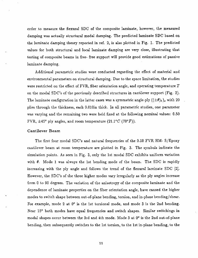
order to measurethe flexural SDC of the composite laminate, however, the measured
damping wasactually structural modal damping. The predicted laminate SDC basedon
the laminate damping theory reported in ref. 2, is also plotted in Fig. 1. The predicted
values for both structural and local laminate damping are very close, illustrating that
testing of composite beamsin free- free support will provide good estimations of passive
laminate damping.
Additional parametric studies were conducted regarding the effect of material and
environmental parameterson structural damping. Due to the spacehmitation, the studies
wererestricted on the effect of FVR, fiber orientation angle,and operating temperature T
on the modal SDC's of the previously described structures in cantilever support (Fig. 2).
The laminate configuration in the latter cases was a symmetric angle-ply ((-l-0)s)s with 20
plies through the thickness, each 0.010in thick. In all parametric studies, one parameter
was varying and the remaining two were held fixed at the following nominal values: 0.50
FVR, +45 ° ply angles, and room temperature (21.1°C (700F)).
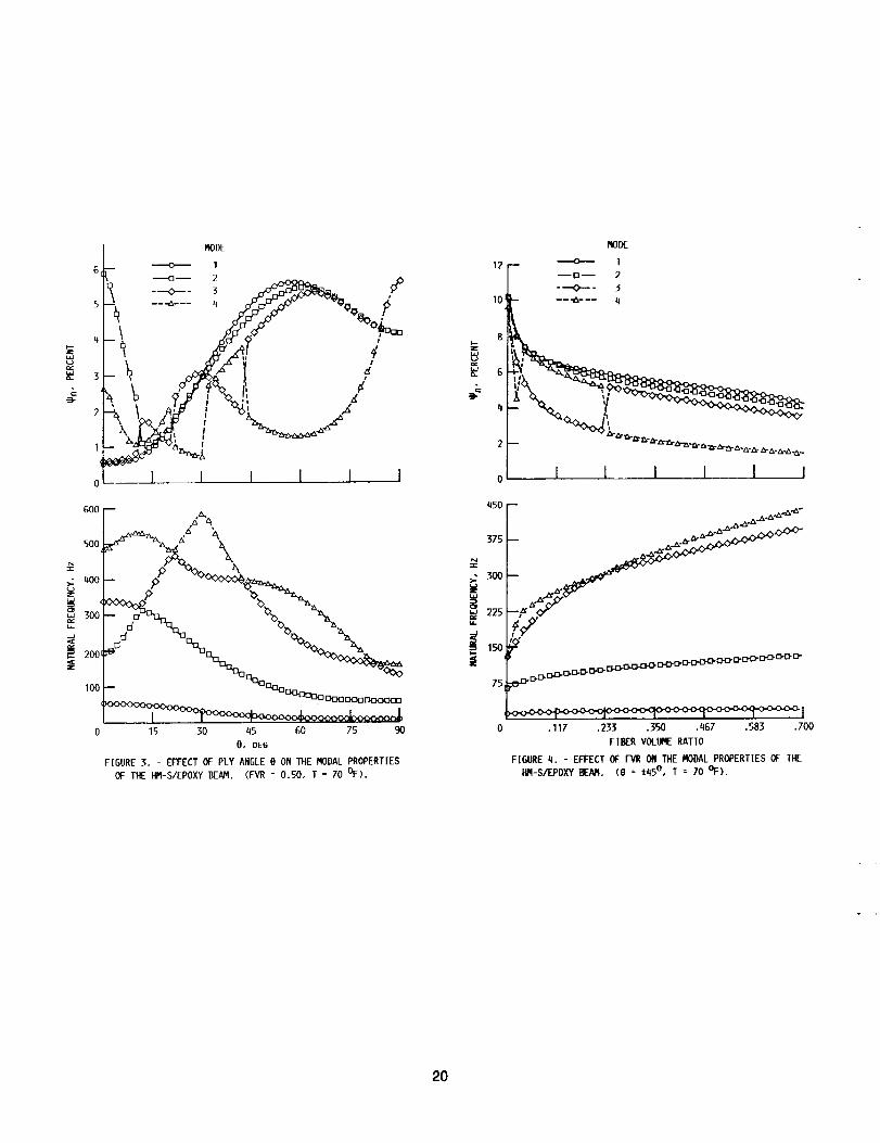
Cantilever Beam
The first four modal SDC's and natural frequencies of the 0.50 FVR HM- S/Epoxy
cantilever beam at room temperature are plotted in Fig. 3. The symbols indicate the
simulation points. As seen in Fig. 3, only the 1st modal SDC exhibits uniform variation
with 0. Mode 1 was always the 1st bending mode of the beam. The SDC is rapidly
increasing with the ply angle and follows the trend of the flexural laminate SDC [2].
However, the SDC's of the three higher modes vary irregularly as the ply angles increase
from 0 to 90 degrees. The variation of the anisotropy of the composite laminate and the
dependence of laminate properties on the fiber orientation angle, have caused the higher
modes to switch shape between out-of-plane bending, torsion, and in-plane bending/shear.
For example, mode 2 at 0 ° is the 1st torsional mode, and mode 3 is the 2rid bending.
Near 15 ° both modes have equal frequencies and switch shapes. Similar switchings in
modal shapes occur between the 3rd and 4th mode. Mode 3 at 0 ° is the 2nd out-of-plane
bending, then subsequently switches to the 1st torsion, to the 1st in-plane bending, to the
11

3rd out-of- plane bending, and finally to the 1st in-plane bending. Mode 4 at 0 ° is the 1st
in-plane bending, and then switches to the 1st torsion, the 3rd bending, the 1st in-plane
bending, and the 3rd bending respectively.
As seen in Fig. 3, at double natural frequencies the respective modal SDC's change
rapidly. This happens because the modes switch shapes, therefore, the strains and stresses
associated with modal SDC's also change near the double natural frequencies resulting in
the observed damping variations. The out-of-plane 1st, 2nd, and 3rd bending modes follow
similar trends to the laminate flexural SDC, but they have different values for ply angles
between 15 ° and 70 ° due to transverse bending in the modes.
Fig. 4 presents the variation of modal SDC's and natural frequencies of a (4-45 °)
cross-ply laminate at room temperature with respect to the FVR. The modal SDC's vary
more uniformly with the FVR than with the ply angle. A switching occurs between modes
3 and 4. This reduction of modal SDC's as the FVR increases was expected [1].
The temperature effect on the modal SDC's and natural frequencies of the 0.50 FVR
(4-45 ° ) cantilever beam is illustrated in Fig. 5. The temperature significantly affects the
modal SDC's but has small effect on the natural frequencies.
Cantilever Plate
Fig. 6 shows the variation of modal SDC's and natural frequencies with respect to
the ply angle. Mode 1 is the 1st out-of-plane bending along the x-axis coupled with some
bending in the y-direction, and mode 2 is mostly the 1st torsional modal shape. Mode 3
is initially the 1st out-of-plane bending in the y-directlon, then as the ply angle increases
is gradually coupled with the 2nd out-of-plane bending mode in x-direction, and near 90 °
is mostly the 2nd bending in x-direction. The 4th mode is mostly the 2nd torsional shape
near 0 °, switches gradually to a coupled out-of-plane bending mode in x and y-directions,
and then switches to the 2nd torsional shape. As seen in Fig. 6, the modal SDC's follow
more or less continuous variations with the ply angle. Again, the modal SDC's follow the
opposite trend of the natural frequencies. In contrast to the beam, the plate is a two-
dimensional structure and its modes are mostly coupled changing shapes gradually. The
12

only exemption is mode 4 near 70% The coupled mode shapes have resulted in different
variations of the modal SDC's than in the previous case of the beam. The modal SDC's
of the plate do not follow closely the trends of laminate damping in bending and torsion.
Furthermore, the results illustrate the importance of the aspect ratio on modal damping.
The curves in Figs. 3 and 6 suggest that specimens of low aspect ratios may yield lower
experimental damping values for angle-ply composites and laminates. The same figures
also demonstrate that measured modal damping values depend on structure type and
should be properly interpreted.
Fig. 7 presents the variation of modal SDC's and natural frequencies of the +45 ° plate
with respect to the FVlZ. The modal SDC's of the plate decrease faster than the respective
SDC's of the beam in Fig. 3, and resemble more the variation of the longitudinal on-axis
damping of unidirectional composites. The fact that the structural damping of the plate
appears more fiber controlled than in the case of the beam has been attributed to the
two-dimensional nature of the plate.
The effect of temperature on the modal SDC's and natural frequencies is shown in
Fig. 8. The modal SDC's are more sensitive to temperature variations than the natural
frequencies. Both SDC's and natural frequencies of the plate are less sensitive to temper-
ature than the SDC's and natural frequencies of the beam. This is in agreement with the
previous observation that the modal SDC's of the plate appear more fiber controlled than
the modal SDC's of the beam.
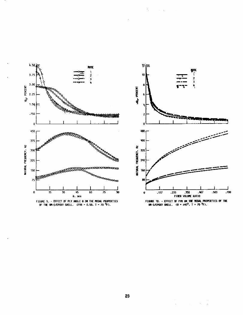
Cylindrical Shell
Compared to the previous beam and plate, the cylindrical shell panel in Fig. 2c
incorporates additional structural coupling between flexural and membrane deflections.
As a result, the cylindrical composite shell has the more complicated mode shapes of the
three structures considered in this study. Fig. 9 shows the variation of modal SDC's and
natural frequencies vs. the ply angle. All modal SDC's have high values at 0 ° and decrease
continuously as the fiber angle is increasing. This type of variation is substantially different
than the SDC's of the beam and plate. The structural membrane-flexure coupling and the
13
coupled mode shapesare in part responsiblefor this type of behavior.
At 0 ° , mode 1 is an opening mode, then is coupled with the 1st torsional shape as
a result of increased material coupling between flexure and torsion, and for angles greater
than 50 ° becomes mostly the 1st torsional modal shape. Mode 2 follows the opposite
pattern. Interestingly, the SDC of the torsional modal shape is not increasing for ply
angles higher than 45 degrees and follows the SDC of the opening mode. Modes 3 and 4
follow almost a similar pattern. Near 00 they are respectively the 2nd opening and 2nd
torsional modal shapes, then they appear coupled and switch shapes near 15 ° , and switch
again near 55 °. In general, the modal SDC's of the shell follow different variations with
the ply angle than the previous two plane composite structures. The results illustrate
the significant effect which curvature may have on the structural damping and dynamic
response.
Typical variations of modal SDC's and natural frequencies with respect to the FVR
are shown in Fig. 10. All modal SDC's decrease rapidly at low FVR's and then decrease
slowly. For FVR's of practical interest, the modal SDC's show small sensitivity to FVR.
The temperature effect on modal SDC's and natural frequencies is shown in Fig. 11.
As in the case of the plate, the modal SDC's increase with temperature. The natural
frequencies decrease slowly as the temperature increases and remain mostly insensitive to
the temperature variation.
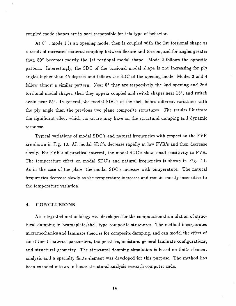
4. CONCLUSIONS
An integrated methodology was developed for the computational simulation of struc-
tural damping in beam/plate/shell type composite structures. The method incorporates
micromechanics and laminate theories for composite damping, and can model the effect of
constituent material parameters, temperature, moisture, general laminate configurations,
and structural geometry. The structural damping simulation is based on finite element
analysis and a specialty finite element was developed for this purpose. The method has
been encoded into an in-house structural-analysis research computer code.
14

Correlations with limited available experimental data, illustrated the accuracy of the
method. The modal SDC's of a composite beam, a composite plate, and a composite shell
panel were simulated. Parametric studies illustrated the sensitivity of modal structural
damping to the fiber volume ratio, ply angles, temperature, and structural shape. The
obtained results lead to the following conclusions:
i. The structural damping has shown significant dependence on structural configuration.
Each modal SDC has also shown great dependence on the shape of the respective mode.
The damping of beam-type structural components is most sensitive to variations of
fiber volume ratio, fiber orientation, and temperature, while the damping of shell-type
components the least.
ii. In case of simple composite structural components (beams), the 1st modal SDC fol-
lows the trend of the ftexural laminate SDC, but the SDC's of the higher modes
have shown a pattern of rapid variations near double natural frequencies. In more
complicated composite structures (plates and shells), the pattern of rapid switchings
was less predominant, however, unpredictability in modal SDC's was induced as a
result of coupled mode shapes, l_Ience, structural analysis is recommended for reliable
predictions of structural damping and proper measured data interpretation.
iii. The aspect ratio has a significant effect on the modal SDC's of composite plane struc-
tures (beams or plates). The effect was more significant for higher modes. Geometric
curvature has also a significant effect on composite structural damping. The results
illustrate that the aspect ratio and warping of specimens may significantly affect the
accuracy of experimental damping measurements in off-axis composite laminates, es-
pecially in higher modes.
iv. PIy angles were found to be the most important parameters affecting the modal damp-
ing of composite structures. Significant alterations in the dynamic response may occur
by tailoring the ply angles. The effect of fiber volume ratio on modal SDC's was less
important.
v. The temperature had also a significant effect on structural modal damping. In all
15

structural cases, structural damping was more sensitive than the natural frequencies
to temperature variations.
Overall, the application examples demonstrated the versatility of the current method
in the dynamic analysis of composite structures. Proper tailoring of the basic composite
materials, lamination, and structural shape may significantly improve the damped dynamic
response of composite structures. The results also suggest that the tailoring of composite
structures for improved damped dynamic performance would be a complicated task and
may be best accomplished by combining the methodology described herein with formal
optimization methods.
ACKNOWLEDGEMENT
This work was performed while the author held a National Research Council - NASA
Research Associateship.
REFERENCES
1. Saravanos D. A. and Chamis C. C. "Unified Micromechanics of Damping for Unidirec-
tional Fiber Composites," NASA TM-102107, (1989). (Also, Journal of Composites
Technology and Research, Spring 1990).
2. Saravanos D. A. and Chamis C. C. "Mechanics of Damping for Fiber Composite Lami-
nates Including Hygro-Therma/Effects," $Oth AIAA Structures, Structural Dynamics,
and Materials Conference, Paper No. 89-1191-CP, Mobile, Alabama, (1989). (Also,
AIAA Journad, Aug. 1990).
3. Murthy P. L. N. and Chamis C. C. "ICAN: Integrated Composite Analyzer," AIAA
Paper 8_-097_, (1984).
4. Hashin Z. "Complex Moduli of Viscoelastic Composites - II. Fiber Reinforced Com-
posite Materials," International Journal of Solid_ and Structures, 6:797-807 (1970).
5. Adams R. D., Fox M. A. O., Flood R. J. L., Friend R. J. and ttewitt R. L. "The
Dynamic Properties of Unidirectional Carbon and Glass Fiber-Reinforced Plastics in
Torsion and Flexure," Journal of Composite Materials, 3:594-603 (1969).
16

6. Chang S. and Bert C. W. "Analysis of Damping for Filamentary CompositeMateri-
als," Composite Materials in Engineering Design, American Society for Metals, Metals
Park, 51-62 (1973).
7. Gibson R. F. and Plunkett R. "Dynamic Mechanical Behavior of Fiber-Reinforced
Composites: Measurement and Analysis," Journal of Composite Materials, 10:325-
341 (1976).
8. Sun C. T., Chaturvedi S. K. and Gibson R. F. "Internal Damping of Short-Fiber
Reinforced Polymer Matrix Composites," Computers and Structures, 20(1-3):391-400
(1985).
9. Suarez S. A., Gibson R. F., Sun C. T. and Chaturvedi S. K. "The Influence of Fiber
Length and Fiber Orientation on Damping and Stiffness of Polymer Composite Ma-
terials," Ezperimental Mechanics, 26(2):175-184 (1986).
10. Schultz A. B. and Tsai S. W. "Measurement of Complex Dynamic Moduli for Lam-
inated Fiber-Reinforced Composites," Journal of Composite Materials, 3:434-443
(1969).
11. Adams R. D. and Bacon D. G. C. "Effect of Fibre Orientation and Laminated Geom-
etry on the Dynamic Properties of CFRP," Journal of Composite Materials, 7:402-428
(1973).
12. Siu C. C. and Bert C. W. "Sinusoidal Response of Composite-Material Plates with
Material Damping," ASME Journal of Engineering for Industry, 603-610 (1974).
13. Cawley P. and Adams R. D. "The Predicted and Experimental Natural Modes of
Free-Free CFRP Plates," Journal of Composite Materials, 12:336-347 (1978).
14. Lin D. X., Ni R. G., and Adams R. D. "Prediction and Measurement of the Vibration
Damping Parameters of Carbon and Glass Fibre-Reinforced Plastic Plates," Journal
of Composite Materials, 18:132-152 (1984).
15. Chamis, C. C., Lark R. F. and Sinclair J. H., "Integrated Theory for Predicting the
Hygrothermomechanical Response of Advanced Composite Structural Components,"
Advanced Composite Materials - Environmental Effects, ASTM STP-658, American
17

Society for Testing and Materials, 160-192 (1978).
16. Ni R. G. and Adams R. D. "The Damping and Dynamic Moduli of Symmetric Lam-
inated Composite Beams - Theoretical and Experimental Results," Journal of Com-
oosite Materials, 18:104-121 (1984).
Table 1. Mechanical properties of HM-S/epoxy system.
Epoxy HM-S Graphite 50o HM-S/Epoxy(ref. [16])
E,,_= 0.500 Mpsi(3.45 GPa)
G,_ = 0.185 Mpsi
(1.27 GPa)¢,,_ = 10.30 %
"¢,,_s = 11.75 %
E¢11 = 55.0 Mpsi(379.3 GPa)
E:22 = 0.9 Mpsi( 6.2 GPa)
G f12 = 1.1 Mpsi( 7.6 GPa)
vii2 = 0.20¢:11 = 0.4 %
¢:._2 = 0.4 %¢:12 = 0.4 %
¢al = 0.45 %
¢z22 = 4.22 %
¢a2 = 7.05 %
18

c=.
d
3,33
2.5(]
1.67
•83)
u FREE-FREE BEAM
0 MEASUREMENT [I(;]
..... LA/IINATETHEORY [2]
of%,
! XI I I _ _I I
30 60 90 120 150 180
O, DEG
FIGURE I. - FIRST MODAL SDC OF THE O.SO FVR (O/90+B/l15+
O/-LIS+B)s HM-S/EPOXY BEAM IN FREE-FREE SUPPORT.
IG
(a) CANTILEVER BEAM.
Z
Y
___.._" 16 -
(b) CANTILEVER PLATE.
Z
(c) CANTILEVER SHELL.
FIGURE 2. - THE THREE COMPOSITES STRUCTURES.
19
-3-
6
5
4
3
2
I
0
MODE
I[-- '--'0-- 2 _ 4')
+...,f
, ,_ _ -_. _._._
- _ J
I I I I I I
I ,.,_'_._. ,/_ \
500_._- _,
200,J -_%% %_%% -+_<++,_
100 - o_:_ _:}o_:} _3o Doc:__oo_o: ]
15 30 45 GO 75 90
0, DEG
FIGURE 3. EFFECT OF PLY ANGLE0 ON TIE MODALPROPERTIES
OF THE I'_-S/EPOXY BEAM. (IL'VR= 0.50, T = 70 OF).
=_
I,L
l_ODE
12 -- ----o--- 1--o-- 2
---¢,--- 3
I 1 I I I I
++50--
75
I0 .117 .233 .350 .467 .583 .700
FIBER VOLUMERATIO
FIGURE _1. - EFFECT OF F"VRON THE MODALPROPERTIESOF THE
I_I-S/EPOXY EAR. (e = ±45 °, T = 70 OF).
20

15--
12
6
MODE
I
_ 2
.... 4 _
I I [ I I ]
420 --
350 --
• 280 --
210-LL
lqO --
70 --
I I I I_, I I20 40 60 80 100 120
T - To, DEG
FIGURE 5. - EFFECT OF TEMPERATUREON THE MODALPROPERTIESOF THE HM-S/EPOXY BEAM. (FVR = 0.50, e = ±q50).
7.5 _" RODE----o---- 1
I --n-- 2 P
3.0
^_ _
°Ts270 f--- . ..,_._-A-_-z_
; 1801--
135
45
15 30 45 60 75 90
0, DEG
FIGURE 6. - EFFECT OF PLY ANGLE 0 ON THE MODAL PROPERTIES
OF THE HM-S/EPOXY PLATE. (FVR = 0.50, T = 70 OF).
21

270 --
225 --
• 180
155u_
45
m j.S_,oS_; J
-- Is SSS /"/'/ _
/------ I 1 I I I I
.117 .233 .350 ,h67 .583 .700
FIBER VOLURERATIO
FIGURE 7. - EFFECT OF F-VR ON THE MODALPROPERTES OF THEHR-S/EPOXY PLATE. (0 = _:_5°, T = 70 °F),
240 --
20O
160z
12oI.L
_ 8o
_0
B
m
I 1 1 1 I I0 20 40 60 80 100 120
T - To, DES
FIGURE 8. - EFFECT OF TEMPERATUREON TIlE MODALPROPERTIES
OF THE HR-S/EPOXY PLATE. (FVR = 0.50, 0 = :L450),
22
.7
!
• 320I-- s s.s_"
0 15 50 q5e, z>e_ FIGORE 10, - EFFECT OF FVU ON THE _ I_OPERT[ES OF "THE
F|GLIRE 9. - EFFECT OF PLY ANGLE0 ON THE RO1)A[.pROPERTIES HIR-S,/1F..POXYSHELL, (0 - :I:elS°, T = 70 OF).
OF THE HR-S/EPOX'YSHELL. (FVR = 0.50, T = 70 OF),
23

1.8
1.5
1.2
x_ .90
c
.50
•30
450
375
300,T .
225
d150
75
0
_ 2
1 ) I I I I
_ _ i_i_ _ _ _ .._im -
I I I I I I20 _0 GO 80 100 120
T - T 0, DEG
FIGURE ll. - EFFECT" OF TEMPERATURE ON THE PA)DAL PROPERTIES
OF THE HIq-SAEPOXY SHELL. (FVR = 0.50, 0 = i450).
24
Natienal Aeronautics and Report Documentation PageSpace Administration
1, Report No. 2. Government Accession No. 3. Recipient's Catalog No.
" NASA TM-102567
5. Report Date4. Title and Subtitle
Computational Simulation of Damping in Composite Structures
7. Author(s)
D.A. Saravanos and C.C. Chamis
9.
12.
Performing Organization Name and Address
National Aeronautics and Space Administration
Lewis Research Center
Cleveland, Ohio 44135-3191
Sponsoring Agency Name and Address
National Aeronautics and Space Administration
Washington, D.C. 20546-0001
6. Performing Organization Code
8. Performing Organization Report No.
E-5143
10. Work Unit No.
505-63-1B
11. Contract or Grant No.
13. Type of Report and Period Covered
Technical Memorandum
14. Sponsoring Agency Code
15 Supplementary Notes
Prepared for the 2nd National Congress in Mechanics, Athens, Greece, June 29--July 1, 1989. D.A. Saravanos,
National Research Council--NASA Research Associate at Lewis Research Center. C.C. Chamis, NASA Lewis
Research Center.
16. Abstract
A computational methodology is developed for the prediction of passive damping in composite structures. The
method involves multiple levels of damping modeling by integrating micromechanics, laminate, and structural
damping theories. The effects of temperature and moisture on structural damping are included. The simulation of
damping in the structural level is accomplished with finite-element discretization. Applications are performed on
graphite/epoxy comlx_sitc bearns, plates, and shells to illustrate the methodology. Additional parametric studies demon-
strate the variation of structural modal damping with respect to ply angles, fiber volume ratio, and temperature.
i 17. Key Words (Suggested by Author(s))
Properties; Damping; Composites; Composite structures;
Fiber volume; Ply angles; Temperature; Beams; Plates;
Shells
18. Distribution Statement
Unclassified - Unlimited
Subject Category 39
19. Security Classif, (of this report) 20. Security Classif. (of this page) 21. No. of pages
Unclassified Unclassified 26
NASAFORM1626OCT86 *For sale by the National Technical Information Service, Springfield, Virginia 22161
22. Price*
A03
