computationally supported sketching …...computationally supported sketching for design 3 using...
TRANSCRIPT
COMPUTATIONALLY SUPPORTED SKETCHING FOR DESIGN
a drawing centered view of design process
Abstract. A drawing centered view of design process focuses on theinterplay between designer expertise, domain knowledge and mediamanipulation. We report on a collection of computational sketchingsoftware systems we have implemented to support the various aspectsof recording, reasoning, and resolving involved in design.
1. Introduction
1.1. MOTIVATION AND RELATED WORK
Ivan Sutherland’s Sketchpad system first demonstrated the power andpromise of interactive, intelligent, pen based graphics to supportengineering design (Sutherland 1963). Among other innovative ideas,Sketchpad employed what later came to be known as object-orientedprogramming, graphics scene-graph hierarchy, interaction with a stylus,on-screen menus, two-handed interaction, and a relaxation-basedconstraint solver to maintain user-specified design constraints on adrawing. In addition to these technological innovations, Sketchpaddemonstrated how computers might support semantically attachedinteractive design drawing, yet for many years little further work wasdone.
Several factors fueled a resurgence of interest in pen-based computing,beginning in the 1990s. Low cost LCD screens and tablet-stylustechnology led to pen-based PDAs such as the Apple Newton, PalmPilot, and others, as well as early pen computers and recently the TabletPC. This new hardware combined with advances in pattern recognitionrekindled interest in drawing-based systems for design. Over the past fewyears a great deal of new work has appeared on sketch design systems.
Many have noted the affordances of sketching in design. Sketching,for example, allows quick exploration of ideas at a high level of
2
abstraction, avoids early commitment to a particular solution, allowingmany alternatives to be explored (Fish and Scrivener 1990; Ullman,Wood et al. 1990). Some experienced designers postpone usingcomputer-aided design tools because they feel that these tools require adegree of precision and commitment that is inappropriate for the earlyphases of design. They prefer to develop conceptual design sketches withpencil and paper, moving to computer-aided tools at a later stage ofdesigning (Cross, Christiaans et al. 1996; Suwa and Tversky 1997).
Many systems aim to understand drawing to provide design feedback.For example, SILK enables a designer to sketch and test a user interfacedesign prototype (Landay 2001). EsQUIsE interprets architecturalsketches for design performance evaluation (Leclercq and Juchmes 2002).An increasing number of researchers consider sketch understanding aknowledge-based task. They argue that computer can provide domainknowledge for the task through sketching. For example, the recognitionof device symbols and connections among them in a motor drivenconveyor system diagram could infer motion by reasoning from domainknowledge (Kurtoglu and Stahovich 2002). The ASSIST mechanicalengineering sketch design system can simulate mechanical movementsand create movies of them, such as a car rolling down a hill (Davis 2002).Forbus et al, working on military “course of action” diagrams minimizethe role of sketch recognition. They argue that sketch recognition isdifficult for computers and easy for people, and the same informationcan be obtained from other sources such as speech and deictic references(Forbus, Ferguson et al. 2001). Their system (Forbus and Usher 2002)therefore attempts only basic recognition of spatial pointers (arrows)combined with speech recognition; their structure-mapping engine(Falkenhainer, Forbus et al. 1990) is used to infer and interpret useractions.
There is also a growing recognition of the value of ambiguity andtolerance for multiple interpretations (Mankoff, Hudson et al. 2000;Gaver, Beaver et al. 2003). Saund’s “perceptual sketching” systems(Saund and Moran 1994; Saund, Fleet et al. 2003) identify patterns in thelines of a sketch that enable users to select and work with the (emergent)objects that they see—regardless of how the sketch was initiallyconstructed. Oviatt & Cohen’s QuickSet system (Oviatt and Cohen2000) combined sketch and speech recognition, showing that cues fromthe sketch recognition can improve speech recognition performance, andvice-versa. Other work on computational support for drawing focuses onusing sketches to produce more refined three-dimensional models(Igarashi and Hughes 2001; Contero, Naya et al. 2003).
1.2. DESIGN: EXPERTISE, KNOWLEDGE, AND MEDIA
Observing designers at work, we find them simultaneously engaged inthree rather different kinds of tasks. At a practical level we see that theywork with various media, for example making drawings and models and
COMPUTATIONALLY SUPPORTED SKETCHING FOR DESIGN 3
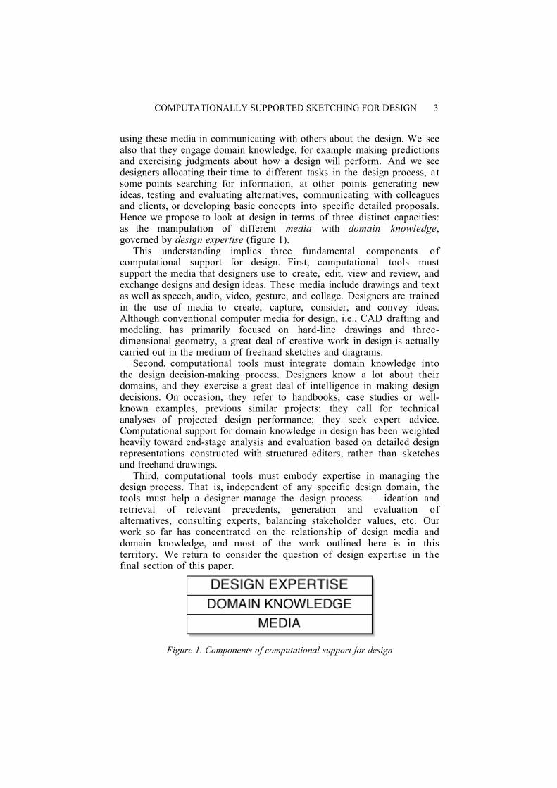
using these media in communicating with others about the design. We seealso that they engage domain knowledge, for example making predictionsand exercising judgments about how a design will perform. And we seedesigners allocating their time to different tasks in the design process, atsome points searching for information, at other points generating newideas, testing and evaluating alternatives, communicating with colleaguesand clients, or developing basic concepts into specific detailed proposals.Hence we propose to look at design in terms of three distinct capacities:as the manipulation of different media with domain knowledge,governed by design expertise (figure 1).
This understanding implies three fundamental components ofcomputational support for design. First, computational tools mustsupport the media that designers use to create, edit, view and review, andexchange designs and design ideas. These media include drawings and textas well as speech, audio, video, gesture, and collage. Designers are trainedin the use of media to create, capture, consider, and convey ideas.Although conventional computer media for design, i.e., CAD drafting andmodeling, has primarily focused on hard-line drawings and three-dimensional geometry, a great deal of creative work in design is actuallycarried out in the medium of freehand sketches and diagrams.
Second, computational tools must integrate domain knowledge intothe design decision-making process. Designers know a lot about theirdomains, and they exercise a great deal of intelligence in making designdecisions. On occasion, they refer to handbooks, case studies or well-known examples, previous similar projects; they call for technicalanalyses of projected design performance; they seek expert advice.Computational support for domain knowledge in design has been weightedheavily toward end-stage analysis and evaluation based on detailed designrepresentations constructed with structured editors, rather than sketchesand freehand drawings.
Third, computational tools must embody expertise in managing thedesign process. That is, independent of any specific design domain, thetools must help a designer manage the design process — ideation andretrieval of relevant precedents, generation and evaluation ofalternatives, consulting experts, balancing stakeholder values, etc. Ourwork so far has concentrated on the relationship of design media anddomain knowledge, and most of the work outlined here is in thisterritory. We return to consider the question of design expertise in thefinal section of this paper.
Figure 1. Components of computational support for design
4
1.3. DRAWING—THE CENTRAL REPRESENTATION IN DESIGN
We take a drawing-centered view of designing. In domains such asmechanical engineering and architectural design where the product is aphysical object, the drawing is typically the single representation that thedesigner uses throughout the designing process, from initial rough sketchto final fabrication drawing. Although other representations (such asspecifications, component lists, and schedules) also play roles, thedrawing remains the focus of design activity.
Our view of design is colored in the first place and most strongly byour own training and experience as practicing designers and by first-handobservation of colleagues and students in the architecture schools wherewe have worked, as well as in other disciplines (such as mechanicalengineering) where design is taught. Although we have done a few studiesof design activity (Do, Gross et al. 1999) we largely rely on empiricalwork by Goldschmidt, Tversky, and others for insights about thecognitive roles and functions of drawing in design (Schon 1992;Goldschmidt 1994; Tversky 2002).
1.4. THREE R’S OF DRAWING AND DESIGN
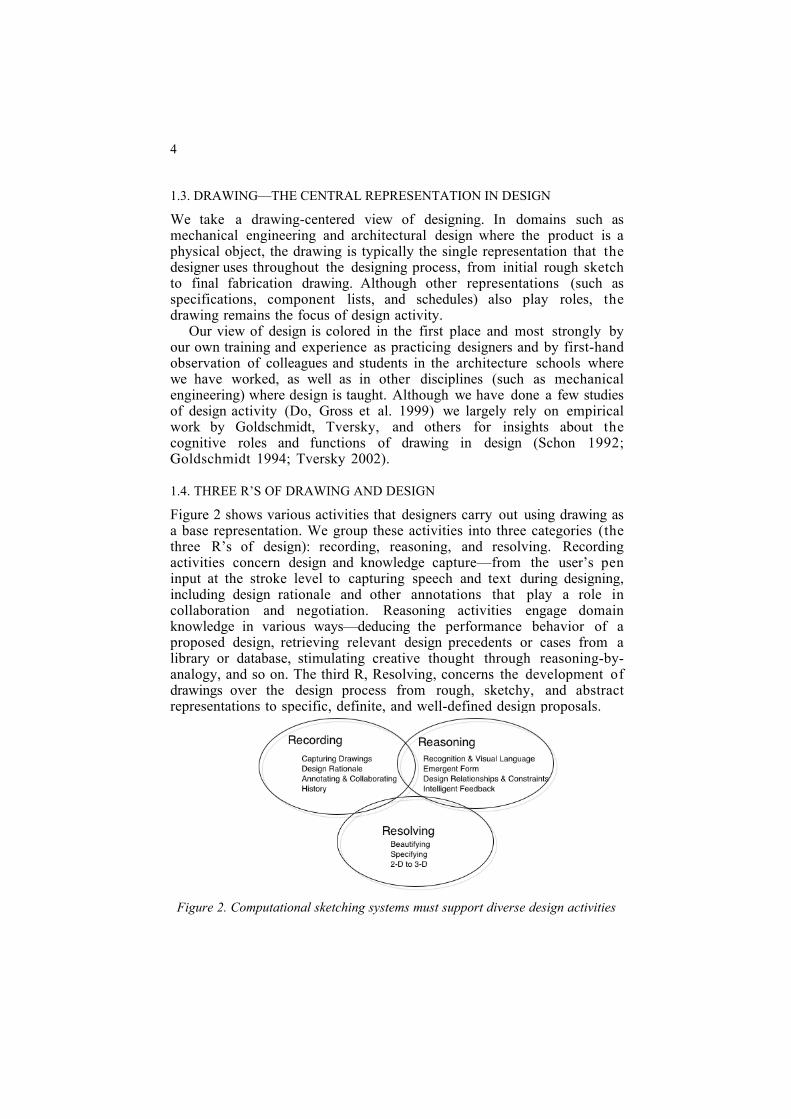
Figure 2 shows various activities that designers carry out using drawing asa base representation. We group these activities into three categories (thethree R’s of design): recording, reasoning, and resolving. Recordingactivities concern design and knowledge capture—from the user’s peninput at the stroke level to capturing speech and text during designing,including design rationale and other annotations that play a role incollaboration and negotiation. Reasoning activities engage domainknowledge in various ways—deducing the performance behavior of aproposed design, retrieving relevant design precedents or cases from alibrary or database, stimulating creative thought through reasoning-by-analogy, and so on. The third R, Resolving, concerns the development ofdrawings over the design process from rough, sketchy, and abstractrepresentations to specific, definite, and well-defined design proposals.
Figure 2. Computational sketching systems must support diverse design activities
COMPUTATIONALLY SUPPORTED SKETCHING FOR DESIGN 5
It is widely recognized that much design takes place collaboratively;drawing plays a central role not only in supporting the individualdesigner’s thinking, but also in team collaboration. These three categoriesof design activities enable not only individual designing, but they mediatecollaboration and communication among members of design teams.
1.5. OUR MULTIFARIOUS EFFORTS TO SUPPORT DESIGN DRAWING
Over the past decade we have engaged in a research program anddeveloped computational support to investigate various aspects ofdesigning. We began with a recognition-based sketching program writtenin Lisp called the Electronic Cocktail Napkin, which formed the platformfor several initial forays into the territory. These efforts focusedprincipally on how to recognize and interpret freehand drawings andextract and embed semantic content. We later extended this work withseveral components focused on other aspects of designing. For the mostpart, we developed each module separately, following the exigencies ofstudent interest and funding. The result is a collection of apparentlydiverse projects that are published in disparate venues. Yet takentogether, we believe that they outline the principal components of adrawing-centered design system. The purpose of the current paper is t oassemble this body of work in relation to our view of design and decisionsupport. In the interest of providing a larger picture, we omit technicaldetails, which can be found in the reports we cite on the individualprojects.
We feel compelled to point out that although most of the examples inthe work described below are from architecture, the model of designingand the systems we have built are quite independent of this domain.Although we would be pleased to see computer support systems forarchitectural design built along the lines we outline, we feel the strategiespresented here could be incorporated into a wide variety of design supportsystems for many domains.
2. Design Activities and systems we have built to support them
2.1. KNOWLEDGE CAPTURE
The capture and management of drawings is central, but importantadditional information about a design often accompanies drawings invarious media—speech, text, photographs, even physical samples ofmaterials—and at various levels of formal representation.
2.1.1. Capturing strokes and recognizing drawing elementsThe Electronic Cocktail Napkin (Gross 1996) captures the designer’s
drawing strokes from a tablet. The program stores raw data as a time-stamped sequence of tuples (x, y, and pressure) which it then analyzes t o
6
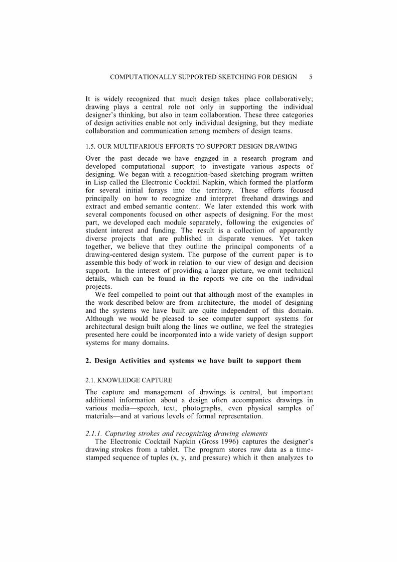
extract features such as drawing speed, corners and points of inflection,direction, bounding box, size, and aspect ratio, and path through a 3x3grid inscribed in the bounding box. These features form the basis of amatching scheme in which glyphs drawn on the tablet are comparedagainst a library of previously trained templates. The recognizer returns aset of most likely matching glyphs along with certainty values and detailsabout the match (for example, that a figure was recognized but drawnupside down). If the program cannot identify a figure, recognition issimply deferred. Figure 3 shows examples of user-trained figures thesystem recognizes.
Figure 3. Electronic Cocktail Napkin recognizes basic symbols and configurations.
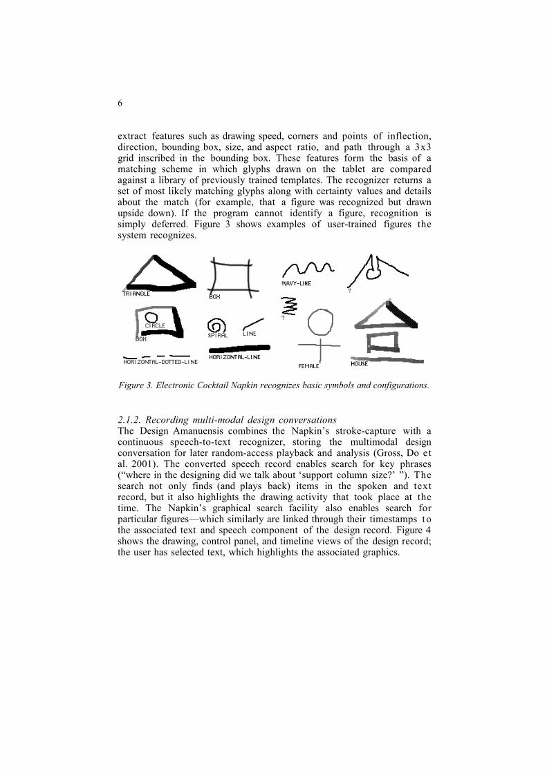
2.1.2. Recording multi-modal design conversationsThe Design Amanuensis combines the Napkin’s stroke-capture with acontinuous speech-to-text recognizer, storing the multimodal designconversation for later random-access playback and analysis (Gross, Do etal. 2001). The converted speech record enables search for key phrases(“where in the designing did we talk about ‘support column size?’ ”). Thesearch not only finds (and plays back) items in the spoken and textrecord, but it also highlights the drawing activity that took place at thetime. The Napkin’s graphical search facility also enables search forparticular figures—which similarly are linked through their timestamps t othe associated text and speech component of the design record. Figure 4shows the drawing, control panel, and timeline views of the design record;the user has selected text, which highlights the associated graphics.
COMPUTATIONALLY SUPPORTED SKETCHING FOR DESIGN 7
Figure 4. Design Amanuensis offers recording, playback, and search of thegraphical and spoken design conversation.
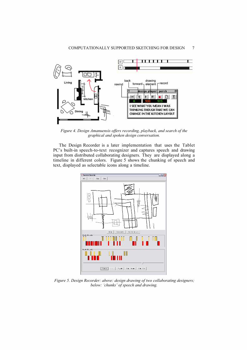
The Design Recorder is a later implementation that uses the TabletPC’s built-in speech-to-text recognizer and captures speech and drawinginput from distributed collaborating designers. They are displayed along atimeline in different colors. Figure 5 shows the chunking of speech andtext, displayed as selectable icons along a timeline.
Figure 5. Design Recorder: above: design drawing of two collaborating designers;below: ‘chunks’ of speech and drawing.
8
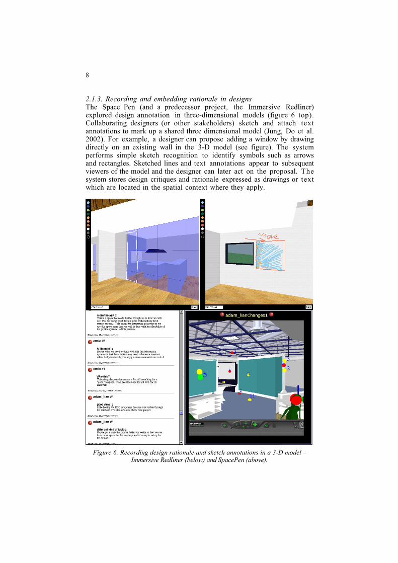
2.1.3. Recording and embedding rationale in designsThe Space Pen (and a predecessor project, the Immersive Redliner)explored design annotation in three-dimensional models (figure 6 top).Collaborating designers (or other stakeholders) sketch and attach textannotations to mark up a shared three dimensional model (Jung, Do et al.2002). For example, a designer can propose adding a window by drawingdirectly on an existing wall in the 3-D model (see figure). The systemperforms simple sketch recognition to identify symbols such as arrowsand rectangles. Sketched lines and text annotations appear to subsequentviewers of the model and the designer can later act on the proposal. Thesystem stores design critiques and rationale expressed as drawings or textwhich are located in the spatial context where they apply.
Figure 6. Recording design rationale and sketch annotations in a 3-D model –Immersive Redliner (below) and SpacePen (above).
COMPUTATIONALLY SUPPORTED SKETCHING FOR DESIGN 9
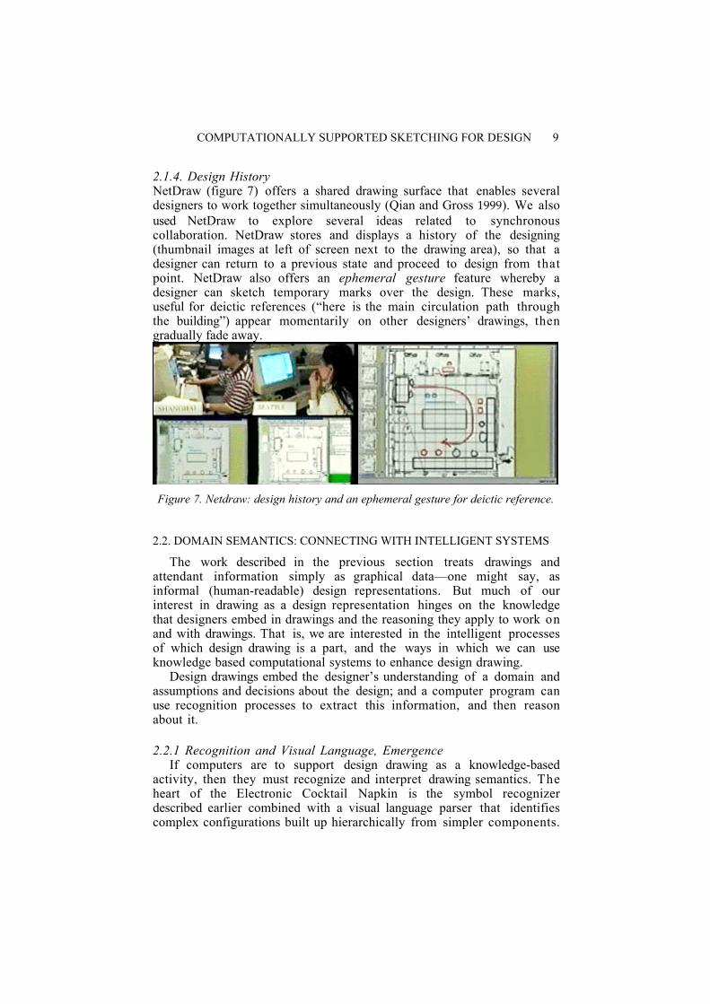
2.1.4. Design HistoryNetDraw (figure 7) offers a shared drawing surface that enables severaldesigners to work together simultaneously (Qian and Gross 1999). We alsoused NetDraw to explore several ideas related to synchronouscollaboration. NetDraw stores and displays a history of the designing(thumbnail images at left of screen next to the drawing area), so that adesigner can return to a previous state and proceed to design from thatpoint. NetDraw also offers an ephemeral gesture feature whereby adesigner can sketch temporary marks over the design. These marks,useful for deictic references (“here is the main circulation path throughthe building”) appear momentarily on other designers’ drawings, thengradually fade away.
Figure 7. Netdraw: design history and an ephemeral gesture for deictic reference.
2.2. DOMAIN SEMANTICS: CONNECTING WITH INTELLIGENT SYSTEMS
The work described in the previous section treats drawings andattendant information simply as graphical data—one might say, asinformal (human-readable) design representations. But much of ourinterest in drawing as a design representation hinges on the knowledgethat designers embed in drawings and the reasoning they apply to work onand with drawings. That is, we are interested in the intelligent processesof which design drawing is a part, and the ways in which we can useknowledge based computational systems to enhance design drawing.
Design drawings embed the designer’s understanding of a domain andassumptions and decisions about the design; and a computer program canuse recognition processes to extract this information, and then reasonabout it.
2.2.1 Recognition and Visual Language, EmergenceIf computers are to support design drawing as a knowledge-based
activity, then they must recognize and interpret drawing semantics. Theheart of the Electronic Cocktail Napkin is the symbol recognizerdescribed earlier combined with a visual language parser that identifiescomplex configurations built up hierarchically from simpler components.
10
For example, the system recognizes a building façade as composed ofwindows, doors, and a roof composed in certain spatial relationships. Thevisual language allows for multiple alternative parses, so that a drawingcan be “read” in several different ways, variously grouping itscomponents into alternative assembly graphs.
The Napkin’s recognition scheme is contextual: depending on thedrawing context the program recognizes symbols and configurationsdifferently (Gross and Do 1996). For example, the same symbol may berecognized in an analog circuit diagram as an inductance and in amechanical drawing as a spring. Conversely, when the Napkin identifies asymbol or configuration that is unique to a context (for example, atransistor symbol in an analog circuit diagram) then it uses this t odetermine the context and thereby resolve pending recognitionambiguities.
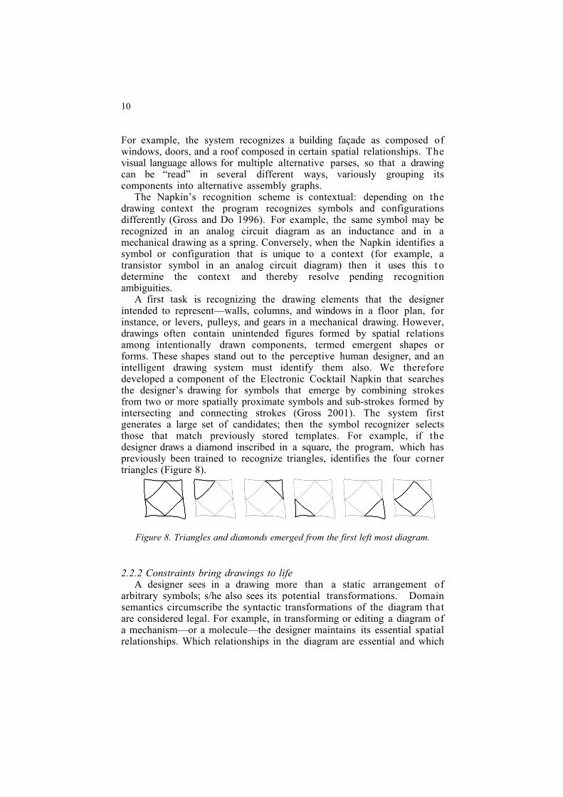
A first task is recognizing the drawing elements that the designerintended to represent—walls, columns, and windows in a floor plan, forinstance, or levers, pulleys, and gears in a mechanical drawing. However,drawings often contain unintended figures formed by spatial relationsamong intentionally drawn components, termed emergent shapes orforms. These shapes stand out to the perceptive human designer, and anintelligent drawing system must identify them also. We thereforedeveloped a component of the Electronic Cocktail Napkin that searchesthe designer’s drawing for symbols that emerge by combining strokesfrom two or more spatially proximate symbols and sub-strokes formed byintersecting and connecting strokes (Gross 2001). The system firstgenerates a large set of candidates; then the symbol recognizer selectsthose that match previously stored templates. For example, if thedesigner draws a diamond inscribed in a square, the program, which haspreviously been trained to recognize triangles, identifies the four cornertriangles (Figure 8).
Figure 8. Triangles and diamonds emerged from the first left most diagram.
2.2.2 Constraints bring drawings to lifeA designer sees in a drawing more than a static arrangement of
arbitrary symbols; s/he also sees its potential transformations. Domainsemantics circumscribe the syntactic transformations of the diagram thatare considered legal. For example, in transforming or editing a diagram ofa mechanism—or a molecule—the designer maintains its essential spatialrelationships. Which relationships in the diagram are essential and which
COMPUTATIONALLY SUPPORTED SKETCHING FOR DESIGN 11
are arbitrary depends on the domain. In an architectural plan geometry isessential; in an analog circuit diagram, it is not.
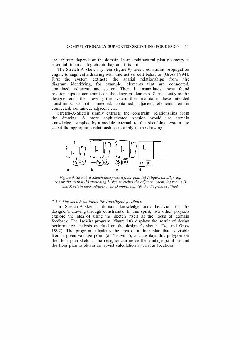
The Stretch-A-Sketch system (figure 9) uses a constraint propagationengine to augment a drawing with interactive edit behavior (Gross 1994).First the system extracts the spatial relationships from thediagram—identifying, for example, elements that are connected,contained, adjacent, and so on. Then it instantiates these foundrelationships as constraints on the diagram elements. Subsequently as thedesigner edits the drawing, the system then maintains these intendedconstraints, so that connected, contained, adjacent, elements remainconnected, contained, adjacent etc.
Stretch-A-Sketch simply extracts the constraint relationships fromthe drawing. A more sophisticated version would use domainknowledge—supplied by a module external to the sketching system—toselect the appropriate relationships to apply to the drawing.
Figure 9. Stretch-a-Sketch interprets a floor plan (a) It infers an align-topconstraint so that (b) stretching L also stretches the adjacent room, (c) rooms D
and K retain their adjacency as D moves left, (d) the diagram rectified.
2.2.3 The sketch as locus for intelligent feedbackIn Stretch-A-Sketch, domain knowledge adds behavior to the
designer’s drawing through constraints. In this spirit, two other projectsexplore the idea of using the sketch itself as the locus of domainfeedback. The IsoVist program (figure 10) displays the result of designperformance analysis overlaid on the designer’s sketch (Do and Gross1997). The program calculates the area of a floor plan that is visiblefrom a given vantage point (an “isovist”), and displays this polygon onthe floor plan sketch. The designer can move the vantage point aroundthe floor plan to obtain an isovist calculation at various locations.
12
Figure 10. IsoVist overlays design performance evaluation on the sketch.
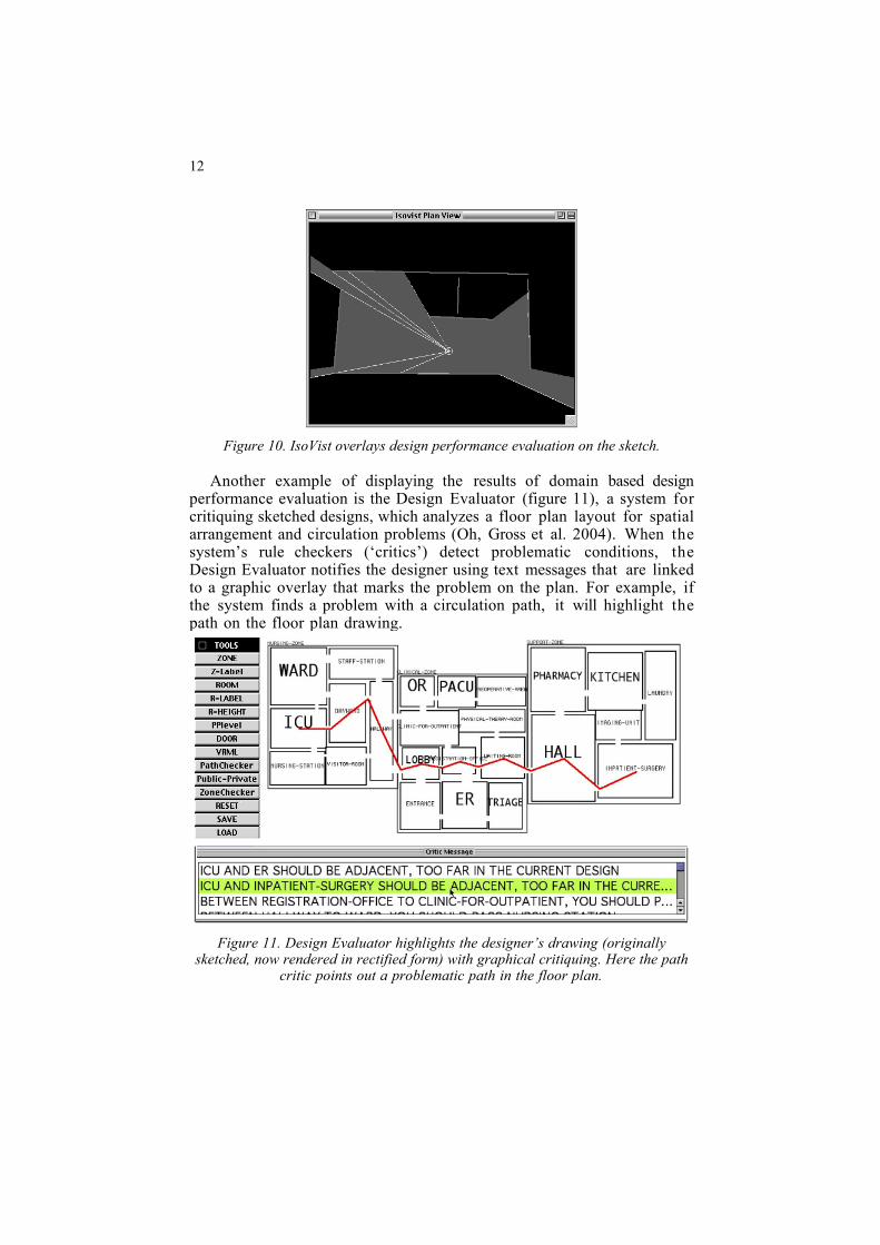
Another example of displaying the results of domain based designperformance evaluation is the Design Evaluator (figure 11), a system forcritiquing sketched designs, which analyzes a floor plan layout for spatialarrangement and circulation problems (Oh, Gross et al. 2004). When thesystem’s rule checkers (‘critics’) detect problematic conditions, theDesign Evaluator notifies the designer using text messages that are linkedto a graphic overlay that marks the problem on the plan. For example, ifthe system finds a problem with a circulation path, it will highlight thepath on the floor plan drawing.
Figure 11. Design Evaluator highlights the designer’s drawing (originallysketched, now rendered in rectified form) with graphical critiquing. Here the path
critic points out a problematic path in the floor plan.
COMPUTATIONALLY SUPPORTED SKETCHING FOR DESIGN 13
2.2.4 External intelligent systemsA design drawing can serve as input to various external design aids or
tools, which can diagnose problems and opportunities in the design,suggest relevant or interesting references, offer advice, or evaluate designperformance.
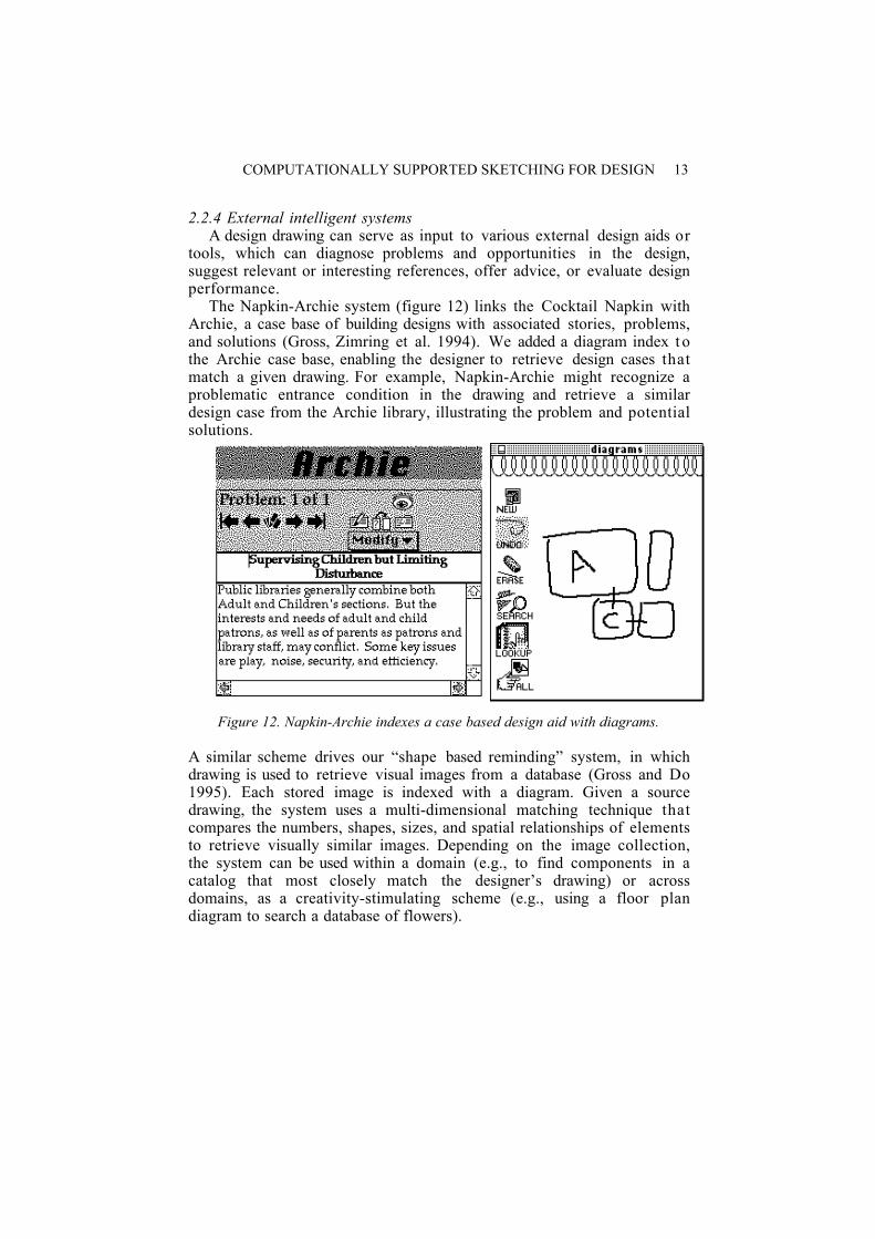
The Napkin-Archie system (figure 12) links the Cocktail Napkin withArchie, a case base of building designs with associated stories, problems,and solutions (Gross, Zimring et al. 1994). We added a diagram index t othe Archie case base, enabling the designer to retrieve design cases thatmatch a given drawing. For example, Napkin-Archie might recognize aproblematic entrance condition in the drawing and retrieve a similardesign case from the Archie library, illustrating the problem and potentialsolutions.
Figure 12. Napkin-Archie indexes a case based design aid with diagrams.
A similar scheme drives our “shape based reminding” system, in whichdrawing is used to retrieve visual images from a database (Gross and Do1995). Each stored image is indexed with a diagram. Given a sourcedrawing, the system uses a multi-dimensional matching technique thatcompares the numbers, shapes, sizes, and spatial relationships of elementsto retrieve visually similar images. Depending on the image collection,the system can be used within a domain (e.g., to find components in acatalog that most closely match the designer’s drawing) or acrossdomains, as a creativity-stimulating scheme (e.g., using a floor plandiagram to search a database of flowers).
14
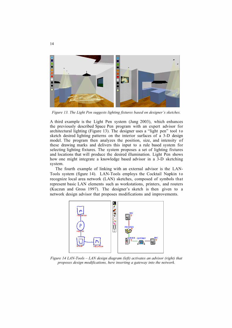
Figure 13. The Light Pen suggests lighting fixtures based on designer’s sketches.
A third example is the Light Pen system (Jung 2003), which enhancesthe previously described Space Pen program with an expert advisor forarchitectural lighting (Figure 13). The designer uses a “light pen” tool t osketch desired lighting patterns on the interior surfaces of a 3-D designmodel. The program then analyzes the position, size, and intensity ofthese drawing marks and delivers this input to a rule based system forselecting lighting fixtures. The system proposes a set of lighting fixturesand locations that will produce the desired illumination. Light Pen showshow one might integrate a knowledge based advisor in a 3-D sketchingsystem.
The fourth example of linking with an external advisor is the LAN-Tools system (figure 14). LAN-Tools employs the Cocktail Napkin t orecognize local area network (LAN) sketches, composed of symbols thatrepresent basic LAN elements such as workstations, printers, and routers(Kuczun and Gross 1997). The designer’s sketch is then given to anetwork design advisor that proposes modifications and improvements.
Figure 14 LAN-Tools – LAN design diagram (left) activates an advisor (right) thatproposes design modifications, here inserting a gateway into the network.
COMPUTATIONALLY SUPPORTED SKETCHING FOR DESIGN 15
2.3. RESOLVING DESIGNS, FROM ABSTRACT TO SPECIFIC
The previous two sections have examined the activities of recordingdesign information and applying domain knowledge and expertise to thedesign drawing. We turn now to the process of specifying a design, frominitial concept to detailed specification. Although we have stressed theimportance of retaining a sketchy look and feel to accurately reflect thedesigner’s level of commitment and decision-making in the early stages,sooner or later the designer must commit to decisions proceed to specifythe design. Computational drawing systems must recognize and supportthis trajectory—allowing vague, ambiguous, and abstract representationsat the outset, supporting the development of more detailed and definiteones, and allowing for some interplay and movement in both directions.
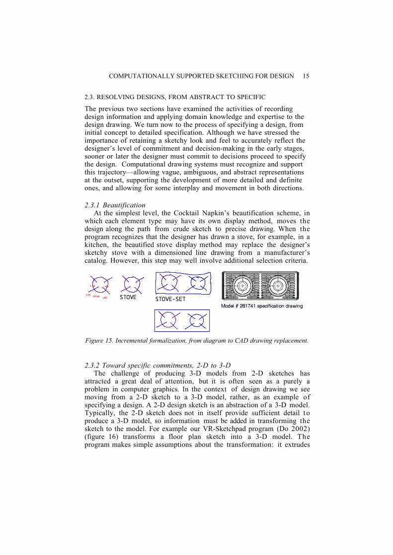
2.3.1 BeautificationAt the simplest level, the Cocktail Napkin’s beautification scheme, in
which each element type may have its own display method, moves thedesign along the path from crude sketch to precise drawing. When theprogram recognizes that the designer has drawn a stove, for example, in akitchen, the beautified stove display method may replace the designer’ssketchy stove with a dimensioned line drawing from a manufacturer’scatalog. However, this step may well involve additional selection criteria.
Figure 15. Incremental formalization, from diagram to CAD drawing replacement.
2.3.2 Toward specific commitments, 2-D to 3-DThe challenge of producing 3-D models from 2-D sketches has
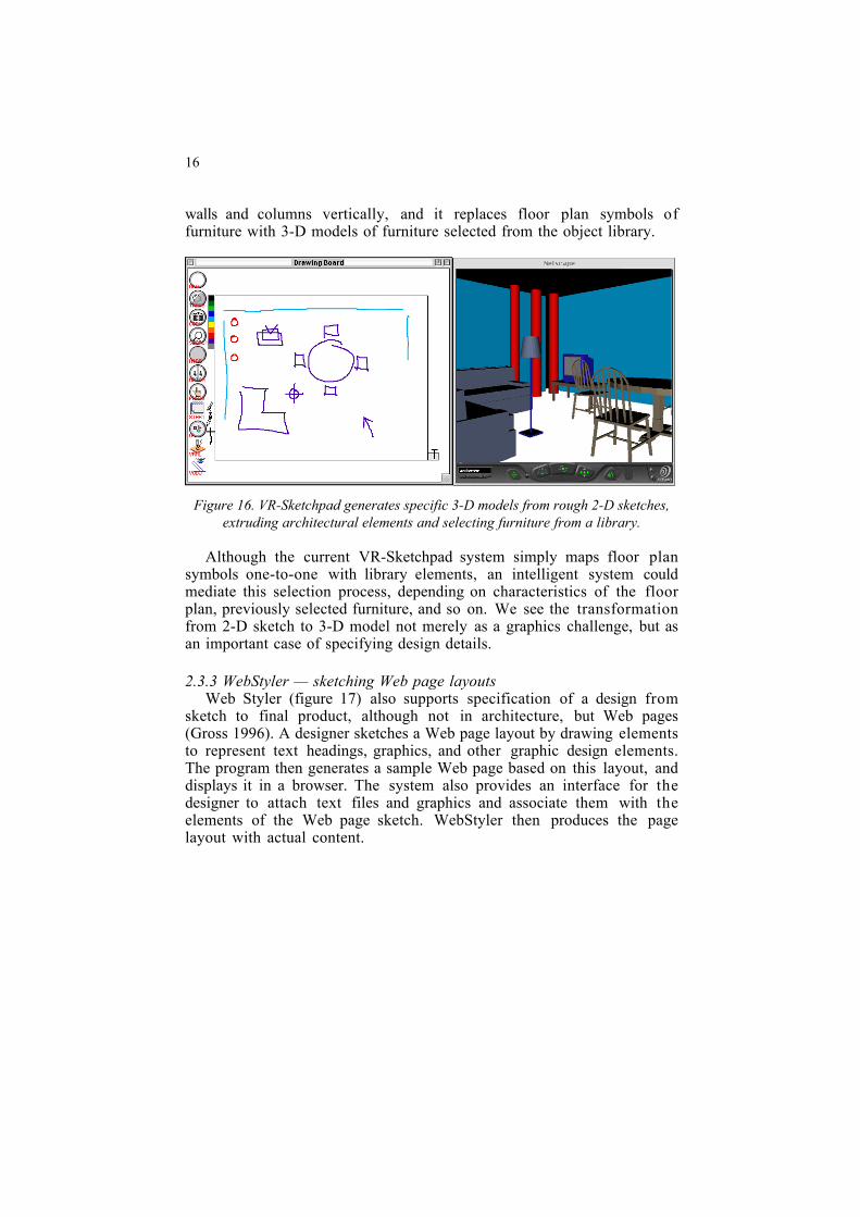
attracted a great deal of attention, but it is often seen as a purely aproblem in computer graphics. In the context of design drawing we seemoving from a 2-D sketch to a 3-D model, rather, as an example ofspecifying a design. A 2-D design sketch is an abstraction of a 3-D model.Typically, the 2-D sketch does not in itself provide sufficient detail t oproduce a 3-D model, so information must be added in transforming thesketch to the model. For example our VR-Sketchpad program (Do 2002)(figure 16) transforms a floor plan sketch into a 3-D model. Theprogram makes simple assumptions about the transformation: it extrudes
16
walls and columns vertically, and it replaces floor plan symbols offurniture with 3-D models of furniture selected from the object library.
Figure 16. VR-Sketchpad generates specific 3-D models from rough 2-D sketches,extruding architectural elements and selecting furniture from a library.
Although the current VR-Sketchpad system simply maps floor plansymbols one-to-one with library elements, an intelligent system couldmediate this selection process, depending on characteristics of the floorplan, previously selected furniture, and so on. We see the transformationfrom 2-D sketch to 3-D model not merely as a graphics challenge, but asan important case of specifying design details.
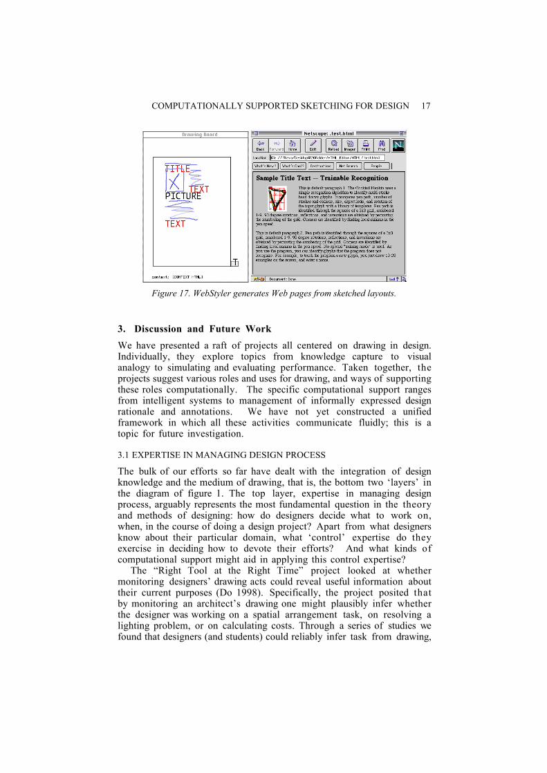
2.3.3 WebStyler — sketching Web page layoutsWeb Styler (figure 17) also supports specification of a design from
sketch to final product, although not in architecture, but Web pages(Gross 1996). A designer sketches a Web page layout by drawing elementsto represent text headings, graphics, and other graphic design elements.The program then generates a sample Web page based on this layout, anddisplays it in a browser. The system also provides an interface for thedesigner to attach text files and graphics and associate them with theelements of the Web page sketch. WebStyler then produces the pagelayout with actual content.
COMPUTATIONALLY SUPPORTED SKETCHING FOR DESIGN 17
Figure 17. WebStyler generates Web pages from sketched layouts.
3. Discussion and Future Work
We have presented a raft of projects all centered on drawing in design.Individually, they explore topics from knowledge capture to visualanalogy to simulating and evaluating performance. Taken together, theprojects suggest various roles and uses for drawing, and ways of supportingthese roles computationally. The specific computational support rangesfrom intelligent systems to management of informally expressed designrationale and annotations. We have not yet constructed a unifiedframework in which all these activities communicate fluidly; this is atopic for future investigation.
3.1 EXPERTISE IN MANAGING DESIGN PROCESS
The bulk of our efforts so far have dealt with the integration of designknowledge and the medium of drawing, that is, the bottom two ‘layers’ inthe diagram of figure 1. The top layer, expertise in managing designprocess, arguably represents the most fundamental question in the theoryand methods of designing: how do designers decide what to work on,when, in the course of doing a design project? Apart from what designersknow about their particular domain, what ‘control’ expertise do theyexercise in deciding how to devote their efforts? And what kinds ofcomputational support might aid in applying this control expertise?
The “Right Tool at the Right Time” project looked at whethermonitoring designers’ drawing acts could reveal useful information abouttheir current purposes (Do 1998). Specifically, the project posited thatby monitoring an architect’s drawing one might plausibly infer whetherthe designer was working on a spatial arrangement task, on resolving alighting problem, or on calculating costs. Through a series of studies wefound that designers (and students) could reliably infer task from drawing,

18
and that specific drawing symbols and configurations were good predictorsof task intentions. We then constructed the Right Tool Right TimeManager. This program watches over the designer’s sketches and—whenit recognizes a symbol belonging to a specific subtask domain such aslighting or cost estimating, it proffers a supporting application (e.g., alighting advisor or a cost calculator).
Although it only considers a small piece of the design expertiseproblem (what is the designer working on and what tools might beappropriate?) the Right Tool at the Right Time project does illustratethe possible relationship between design drawing and questions ofexpertise. Although one can—conceptually—distinguish the use of media,the application of knowledge, and the exercise of expertise, in designpractice the three are often intertwined.
3.2 OTHER MEDIA (GESTURE, COLLAGE, PHYSICAL MODELS)
We have taken a drawing-centered view of designing, focusing on theroles that drawing plays in design, the activities that designers do withdrawings, and the ways in which computational tools might support thoseactivities. However, we recognize that real-world designing is muchricher. Designers employ other media as well in the course of designing,for example, physical models, collages, text, speech, drawing, and gestureinteraction. In other, related, projects we have built systems to supportthe use of these media for designing, and we plan future work to integratethese efforts into our drawing centered model of design.
Acknowledgements
This research was supported in part by the National Science Foundation underGrants IIS-96-19856 and IIS-00-96138. The views and findings contained in thismaterial are those of the authors and do not necessarily reflect the views of theNational Science Foundation.
References
Contero, M., F. Naya, et al. (2003). CIGRO: A Minimal Instruction Set CalligraphicInterface for Sketch-Based Modelling. Computational Science and ItsApplications - ICCSA 2003 (Lecture Notes in Computer Science) . V. Kuma and
P. L'Ecuyer. Montreal, Springer.
Cross, N., H. Christiaans, et al., Eds. (1996). Analyzing Design Activity . New York, John
Wiley & Sons.
Davis, R. (2002). Sketch Understanding in design: Overview of Work at the MIT AI lab.Sketch Understanding, Papers from the 2002 AAAI Symposium , American
Association for Artificial Intelligence (AAAI): 24-31.
COMPUTATIONALLY SUPPORTED SKETCHING FOR DESIGN 19
Do, E. Y.-L. (1998). The Right Tool at the Right Time: Investigation of Freehand Drawingas an Interface to Knowledge Based Design Tools, Ph.D. dissertation, GeorgiaInstitute of Technology.
Do, E. Y.-L. (2002). "Drawing Marks, Acts, and Reacts, toward a computational sketchinginterface for architectural design." AIEDAM, Artificial Intelligence forEngineering Design, Analysis and Manufacturing, 16(3): 149-171.
Do, E. Y.-L. and M. D. Gross (1997). Tools for visual and spatial analysis of CAD models.Computer Assisted Architectural Design Futures ‘97 . R. Junge. Dordrecht,
Kluwer Academic Publishers: 189-202.
Do, E. Y.-L., M. D. Gross, et al. (1999). Drawing and Design Intentions -- an Investigationof freehand drawing conventions in design . Design Thinking Research
Symposium, Cambridge MA.
Falkenhainer, B., K. D. Forbus, et al. (1990). "The Structure Mapping Engine." ArtificialIntelligence 41(1): 1-63.
Fish, J. and S. Scrivener (1990). "Amplifying the Mind's Eye: Sketching and VisualCognition." Leonardo 23(1): 117-126.
Forbus, K. D., R. W. Ferguson, et al. (2001). Towards a computational model of sketching.Proceedings of the 6th international conference on Intelligent user interfaces .
Santa Fe, New Mexico, United States, ACM Press: 77-83.
Forbus, K. D. and J. M. Usher (2002). Sketching for Knowledge Capture: A ProgressReport. Proceedings of the 7th international conference on intelligent userinterfaces (IUI) . San Francisco, ACM: 71-77.
Gaver, W. W., J. Beaver, et al. (2003). Ambiguity as a Resource for Design. Proceedings ofthe ACM Conference on Human Factors (CHI 2003) . ACM: 233-240.
Goldschmidt, G. (1994). "Sketching in Design: Past, Present and Future." 132-137.
Gross, M. D. (1994). Stretch-A-Sketch, a Dynamic Diagrammer. Proceedings of the IEEESymposium on Visual Languages '94 . A. Ambler, IEEE Press: 232-238.
Gross, M. D. (1996). "The Electronic Cocktail Napkin - working with diagrams." DesignStudies 17(1): 53-70.
Gross, M. D. (2001). Emergence in a Recognition Based Drawing Interface,. Visual andSpatial Reasoning II . B. T. J. Gero, T. Purcell. Sydney Australia, Key Centre for
Design Cognition and Computing: 51-65.
Gross, M. D. and E. Y.-L. Do (1995). Shape Based Reminding in Creative Design. GlobalDesign Studio: Computer Aided Architectural Design Futures '95 . M. Tan and
R. Teh. Singapore. 2: 1-11.
Gross, M. D. and E. Y.-L. Do (1996). Ambiguous Intentions. Proceedings, ACMSymposium on User Interface Software and Technology (UIST '96) . Seattle, WA,
ACM SIGGRAPH and SIGCHI: 183-192.
Gross, M. D., E. Y.-L. Do, et al. (2001). The Design Amanuensis : an Instrument forMultimodal Design Capture. Proceedings Computer Aided Architectural DesignFutures 2001 . Eindhoven, Netherlands., Kluwer: 1-13.
Gross, M. D., J. Lewin, E, Do, K. Kuczun, and A. Warmack (1996). Drawing as an Interfaceto Knowledge Based Design, Colorado Advanced Software Institute.
20
Gross, M. D., C. Zimring, et al. (1994). Using Diagrams to Access a Case Base ofArchitectural Designs. Artificial Intelligence in Design '94 . J. Gero. Lausanne,
Kluwer: 129-144.
Igarashi, T. and J. F. Hughes (2001). A Suggestive Interface for 3D Drawing. Proceedingsof the ACM Symposium on User Interface Software and Technology (UIST) :
173-181.
Jung, T., E. Do, et al. (2002). Sketching Annotations in 3D on the Web . ACM Conference
on Human Factors (SIGCHI), Minneapolis, ACM Press.
Kuczun, K. and M. D. Gross (1997). Local Area Network Tools and Tasks. ACMConference on Designing Interactive Systems 1997 . Amsterdam: 215-221.
Kurtoglu, T. and T. F. Stahovich (2002). Interpreting Schematic Sketches Using PhysicalReasoning. AAAI Spring Symposium on Sketch Understanding ., AAAI Press:
78-85.
Landay, J. a. M. B. ( 2001). "Sketching Interfaces: Toward More Human Interface Design."IEEE Computer : 56-64.
Leclercq, P. and R. Juchmes (2002). "The Absent Interface In Design Engineering."Artificial Intelligence for Engineering Design, Analysis and Manufacturing (AIEDAM) 16(3): 219 - 227.
Mankoff, J., S. E. Hudson, et al. (2000). Providing Integrated Toolkit-Level Support forAmbiguity in Recognition-Based Interfaces. CHI 2000 , ACM Press: 368-375.
Oh, Y., M. D. Gross, et al. (2004). Design Evaluator: critiquing freehand sketches.Proceedings of Generative Computer Aided Design Systems : in review.
Oviatt, S. and P. Cohen (2000). "Multimodal Interfaces That Process What ComesNaturally." Communications of the ACM 43(3): 45-53.
Qian, D. and M. D. Gross (1999). Collaborative Design with NetDraw. Proceedings ofComputer Aided Architectural Design Futures ’99 . G. Augenbroe and C.
Eastman. Atlanta, Kluwer.
Saund, E., D. Fleet, et al. (2003). Perceptually-Supported Image Editing of Text andGraphics. ACM conference on User Interface Software Technology . Vancouver,
ACM.
Saund, E. and T. P. Moran (1994). A Perceptually-Supported Sketch Editor . ACM
Symposium on User Interface Software and Technology, ACM Press.
Schon, D. A., and Wiggins, G. (1992). "Kinds of Seeing and their functions in designing."Design Studies 13(#2): 135-156.
Sutherland, I. (1963). Sketchpad - a Graphical Man-Machine Interface, M.I.T.Suwa, M. and B. Tversky (1997). "What architects and students perceive in their
sketches: A protocol analysis." Design Studies (18): 385-403.
Tversky, B. (2002). What do Sketches say about Thinking? 2002 AAAI SpringSymposium Series -- Sketch Understanding . T. Stahovich, J. Landay and R.
Davis, AAAI.
Ullman, D., S. Wood, et al. (1990). "The Importance of Drawing in the Mechanical DesignProcess." Computers and Graphics 14(2): 263-274.