computations on wings with full-span oscillating control ...€”2013–216601 computations on...
TRANSCRIPT

NASA/TM—2013–216601
Computations on Wings with Full-Span Oscillating Control Surfaces using Navier-Stokes Equations Guru P. Guruswamy Ames Research Center, Moffett Field, California
May 2013
https://ntrs.nasa.gov/search.jsp?R=20140010808 2018-07-14T09:53:43+00:00Z

NASA STI Program ... in Profile
Since its founding, NASA has been dedicated to the advancement of aeronautics and space science. The NASA scientific and technical information (STI) program plays a key part in helping NASA maintain this important role.
The NASA STI program operates under the auspices of the Agency Chief Information Officer. It collects, organizes, provides for archiving, and disseminates NASA’s STI. The NASA STI program provides access to the NASA Aeronautics and Space Database and its public interface, the NASA Technical Reports Server, thus providing one of the largest collections of aeronautical and space science STI in the world. Results are published in both non-NASA channels and by NASA in the NASA STI Report Series, which includes the following report types:
TECHNICAL PUBLICATION. Reports of
completed research or a major significant phase of research that present the results of NASA Programs and include extensive data or theoretical analysis. Includes compila- tions of significant scientific and technical data and information deemed to be of continuing reference value. NASA counter-part of peer-reviewed formal professional papers but has less stringent limitations on manuscript length and extent of graphic presentations.
TECHNICAL MEMORANDUM. Scientific and technical findings that are preliminary or of specialized interest, e.g., quick release reports, working papers, and bibliographies that contain minimal annotation. Does not contain extensive analysis.
CONTRACTOR REPORT. Scientific and technical findings by NASA-sponsored contractors and grantees.
CONFERENCE PUBLICATION. Collected papers from scientific and technical conferences, symposia, seminars, or other meetings sponsored or co-sponsored by NASA.
SPECIAL PUBLICATION. Scientific, technical, or historical information from NASA programs, projects, and missions, often concerned with subjects having substantial public interest.
TECHNICAL TRANSLATION. English-language translations of foreign scientific and technical material pertinent to NASA’s mission.
Specialized services also include organizing and publishing research results, distributing specialized research announcements and feeds, providing information desk and personal search support, and enabling data exchange services.
For more information about the NASA STI program, see the following:
Access the NASA STI program home page
at http://www.sti.nasa.gov
E-mail your question to [email protected]
Fax your question to the NASA STI Information Desk at 443-757-5803
Phone the NASA STI Information Desk at 443-757-5802
Write to: STI Information Desk NASA Center for AeroSpace Information7115 Standard Drive Hanover, MD 21076-1320
.
NASA/TM—2013–216601
Computations on Wings with Full-Span Oscillating Control Surfaces using Navier-Stokes Equations Guru P. Guruswamy Ames Research Center, Moffett Field, California
National Aeronautics and Space Administration Ames Research Center Moffett Field, CA 94035-1000
May 2013

Click here: Press F1 key (Windows) or Help key (Mac) for help
Available from:
Click here: Press F1 key (Windows) or Help key (Mac) for help This report is also available in electronic form at
http://www.nas.nasa.gov/publications/reports/reports.html
NASA Center for AeroSpace Information
7115 Standard Drive
Hanover, MD 21076-1320
443-757-5802
Computations on Wings with Full-Span Oscillating Control Surfaces using Navier-Stokes Equations
Guru P. Guruswamy
NASA Advanced Supercomputing Division, Ames Research Center Moffett Field, CA
Abstract
This paper presents a time-accurate procedure for computing unsteady aerodynamic forces on wings with a full-span oscillating control surface by using sheared grids. In this procedure, the flow is computed by solving the unsteady Reynolds-Averaged Navier-Stokes (RANS) equations in conjunction with the one-equation Spalart-Allmaras turbulence model. A module to model control surface oscillations is embedded into a general purpose RANS solver. Unsteady pressures and forces are validated with experimental data for wall-to-wall mounted and finite-tip wings with full span control surfaces. The effect of Mach number on unsteady aerodynamic loads is investigated for the transonic flow regime.
I. Introduction he use of active controls for fixed-wing aircraft [1] and rotorcraft [2] is becoming more important for modern configurations. Advanced transport designs, such as blended wing-bodies [3], need active controls to achieve
safe and efficient flight. Efforts to reduce the vibrations of helicopter blades with use of active-controls are also in progress [2]. Modeling oscillating control surfaces using linear aerodynamics theory is well established. However, higher-fidelity methods are needed to account for nonlinear effects, such as those that occur in transonic flow [4]. The aeroelastic responses of a wing with an oscillating control surface, computed using the transonic small perturbation (TSP) theory, have been shown to cause important transonic flow effects [5] such as a reversal of control surface effectiveness that occurs as the shock wave crosses the hinge line. In order to account for flow complexities such as blade-vortex interactions of rotor blades [6] and leading edge vortex-induced aeroelastic oscillations of blended wing body transports [3, 7], higher-fidelity methods based on the Navier-Stokes equations are used. Since the original development of moderate-fidelity TSP methods [5, 8], higher-fidelity flow equations have come into use to model oscillating control surfaces. The first successful computation using TSP for a fixed wing with an oscillating control surface in the transonic flow regime is reported in Ref. 8. Computations using transpiration boundary conditions (without physically moving the control surface) were made in Ref. 9, using the full-potential theory. Ref. 10 presents a procedure that uses the Navier-Stokes equations with moving-sheared grids and demonstrates up to 8 degrees of control-surface amplitude, using a single grid. Later, this procedure was extended to accommodate larger amplitudes, based on sliding grid zones [11]. Reference 12 reports an effort using a sheared grid to validate results for a transport wing. The sheared grid method implemented in the Euler/Navier-Stokes-based aeroelastic code ENSAERO [13] was successfully applied to active control design by industry [14]. To date, the sheared grid technique of modeling control surfaces has been successfully applied to complex geometries using patched structured grids [15] and has been implemented on parallel computers [16]. The aeroelastic code HIMAP [17] based on the Navier-Stokes equations using patched structured grids includes a control surface module that has been implemented in a parallel computing environment. In addition to such patched structured grid codes, aeroelastic capabilities have been implemented in OVERFLOW [18], which is based on the RANS equations and uses overset grids, which has been well established to model flows over non-oscillating control surfaces [19]. Recently, an oscillating control surface capability for rotorcraft was added to OVERFLOW using overset grids in gaps [20] and was validated for integrated air loads. Ref. 20 reports significant differences between computations and measurements, particularly for flap moments. While the approach presented in Ref. 20 promises to be accurate, a promise that has yet to be realized in such quantities as unsteady surface pressures, it also requires more grid points and a more complicated grid generation process. Time step restrictions associated with tightly spaced grid points in gaps can also be an issue with this approach.
T
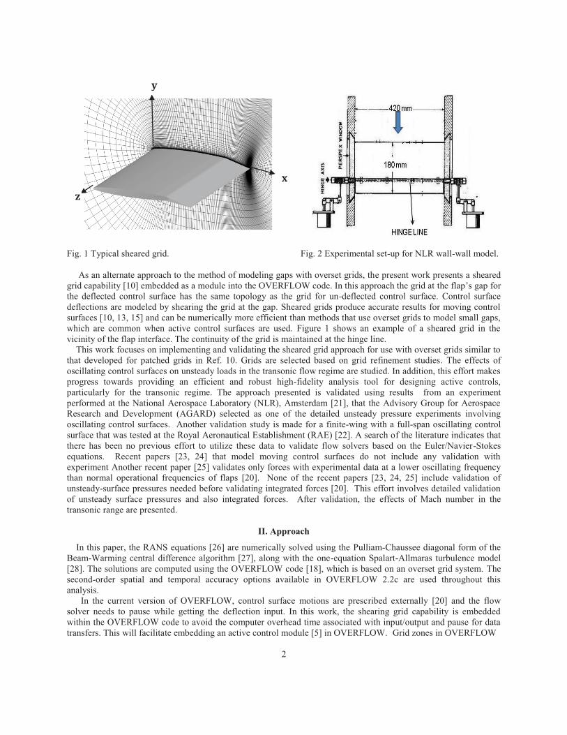
Fig. 1 Typical sheared grid.
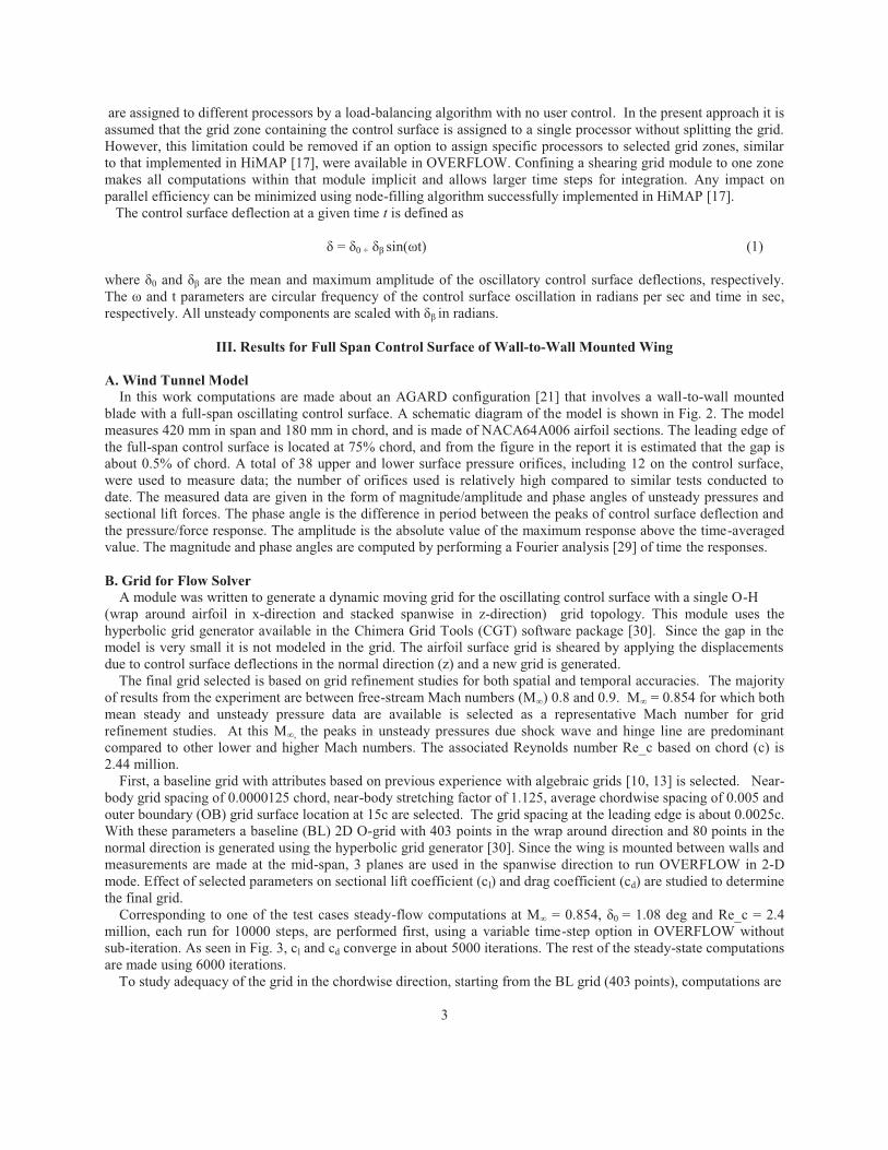
Fig. 2 Experimental set-up for NLR wall-wall model.
As an alternate approach to the method of modeling gaps with overset grids, the present work presents a sheared grid capability [10] embedded as a module into the OVERFLOW code. In this approach the grid at the flap’s gap for the deflected control surface has the same topology as the grid for un-deflected control surface. Control surface deflections are modeled by shearing the grid at the gap. Sheared grids produce accurate results for moving control surfaces [10, 13, 15] and can be numerically more efficient than methods that use overset grids to model small gaps, which are common when active control surfaces are used. Figure 1 shows an example of a sheared grid in the vicinity of the flap interface. The continuity of the grid is maintained at the hinge line. This work focuses on implementing and validating the sheared grid approach for use with overset grids similar to that developed for patched grids in Ref. 10. Grids are selected based on grid refinement studies. The effects of oscillating control surfaces on unsteady loads in the transonic flow regime are studied. In addition, this effort makes progress towards providing an efficient and robust high-fidelity analysis tool for designing active controls, particularly for the transonic regime. The approach presented is validated using results from an experiment performed at the National Aerospace Laboratory (NLR), Amsterdam [21], that the Advisory Group for Aerospace Research and Development (AGARD) selected as one of the detailed unsteady pressure experiments involving oscillating control surfaces. Another validation study is made for a finite-wing with a full-span oscillating control surface that was tested at the Royal Aeronautical Establishment (RAE) [22]. A search of the literature indicates that there has been no previous effort to utilize these data to validate flow solvers based on the Euler/Navier-Stokes equations. Recent papers [23, 24] that model moving control surfaces do not include any validation with experiment Another recent paper [25] validates only forces with experimental data at a lower oscillating frequency than normal operational frequencies of flaps [20]. None of the recent papers [23, 24, 25] include validation of unsteady-surface pressures needed before validating integrated forces [20]. This effort involves detailed validation of unsteady surface pressures and also integrated forces. After validation, the effects of Mach number in the transonic range are presented.
II. Approach
In this paper, the RANS equations [26] are numerically solved using the Pulliam-Chaussee diagonal form of the Beam-Warming central difference algorithm [27], along with the one-equation Spalart-Allmaras turbulence model [28]. The solutions are computed using the OVERFLOW code [18], which is based on an overset grid system. The second-order spatial and temporal accuracy options available in OVERFLOW 2.2c are used throughout this analysis. In the current version of OVERFLOW, control surface motions are prescribed externally [20] and the flow solver needs to pause while getting the deflection input. In this work, the shearing grid capability is embedded within the OVERFLOW code to avoid the computer overhead time associated with input/output and pause for data transfers. This will facilitate embedding an active control module [5] in OVERFLOW. Grid zones in OVERFLOW
2
x
y
z
are assigned to different processors by a load-balancing algorithm with no user control. In the present approach it is assumed that the grid zone containing the control surface is assigned to a single processor without splitting the grid. However, this limitation could be removed if an option to assign specific processors to selected grid zones, similar to that implemented in HiMAP [17], were available in OVERFLOW. Confining a shearing grid module to one zone makes all computations within that module implicit and allows larger time steps for integration. Any impact on parallel efficiency can be minimized using node-filling algorithm successfully implemented in HiMAP [17]. The control surface deflection at a given time t is defined as δ = δ0 + δβ sin(ωt) (1) where δ0 and δβ are the mean and maximum amplitude of the oscillatory control surface deflections, respectively. The ω and t parameters are circular frequency of the control surface oscillation in radians per sec and time in sec, respectively. All unsteady components are scaled with δβ in radians.
III. Results for Full Span Control Surface of Wall-to-Wall Mounted Wing A. Wind Tunnel Model In this work computations are made about an AGARD configuration [21] that involves a wall-to-wall mounted blade with a full-span oscillating control surface. A schematic diagram of the model is shown in Fig. 2. The model measures 420 mm in span and 180 mm in chord, and is made of NACA64A006 airfoil sections. The leading edge of the full-span control surface is located at 75% chord, and from the figure in the report it is estimated that the gap is about 0.5% of chord. A total of 38 upper and lower surface pressure orifices, including 12 on the control surface, were used to measure data; the number of orifices used is relatively high compared to similar tests conducted to date. The measured data are given in the form of magnitude/amplitude and phase angles of unsteady pressures and sectional lift forces. The phase angle is the difference in period between the peaks of control surface deflection and the pressure/force response. The amplitude is the absolute value of the maximum response above the time-averaged value. The magnitude and phase angles are computed by performing a Fourier analysis [29] of time the responses. B. Grid for Flow Solver A module was written to generate a dynamic moving grid for the oscillating control surface with a single O-H (wrap around airfoil in x-direction and stacked spanwise in z-direction) grid topology. This module uses the hyperbolic grid generator available in the Chimera Grid Tools (CGT) software package [30]. Since the gap in the model is very small it is not modeled in the grid. The airfoil surface grid is sheared by applying the displacements due to control surface deflections in the normal direction (z) and a new grid is generated. The final grid selected is based on grid refinement studies for both spatial and temporal accuracies. The majority of results from the experiment are between free-stream Mach numbers (M∞) 0.8 and 0.9. M∞ = 0.854 for which both mean steady and unsteady pressure data are available is selected as a representative Mach number for grid refinement studies. At this M∞, the peaks in unsteady pressures due shock wave and hinge line are predominant compared to other lower and higher Mach numbers. The associated Reynolds number Re_c based on chord (c) is 2.44 million. First, a baseline grid with attributes based on previous experience with algebraic grids [10, 13] is selected. Near- body grid spacing of 0.0000125 chord, near-body stretching factor of 1.125, average chordwise spacing of 0.005 and outer boundary (OB) grid surface location at 15c are selected. The grid spacing at the leading edge is about 0.0025c. With these parameters a baseline (BL) 2D O-grid with 403 points in the wrap around direction and 80 points in the normal direction is generated using the hyperbolic grid generator [30]. Since the wing is mounted between walls and measurements are made at the mid-span, 3 planes are used in the spanwise direction to run OVERFLOW in 2-D mode. Effect of selected parameters on sectional lift coefficient (cl) and drag coefficient (cd) are studied to determine the final grid. Corresponding to one of the test cases steady-flow computations at M∞ = 0.854, δ0 = 1.08 deg and Re_c = 2.4 million, each run for 10000 steps, are performed first, using a variable time-step option in OVERFLOW without sub-iteration. As seen in Fig. 3, cl and cd converge in about 5000 iterations. The rest of the steady-state computations are made using 6000 iterations. To study adequacy of the grid in the chordwise direction, starting from the BL grid (403 points), computations are
3

made using a series of grids with increased spacing: double the spacing (203 points), quadruple the spacing (103 points) and octuple the spacing (53 points), while keeping the remaining of the grid parameters the same. This is Fig. 3 Convergence of steady cl and cd at M∞ = 0.854, δ0 = 1.0 deg and Re_c = 2.44 million.
Fig. 4 Effect of chordwise spacing on cl and cd at M∞ = 0.854, δ0 = 1.0 deg and Re_c = 2.44 million.
accomplished by modifying the baseline grid (403 points) using the cubic spline interpolations in CGT [30]. Figure 4 shows the effect of grid refinement in the x-direction on cl and cd. As seen, both cl and cd converge for the baseline grid. Next normal grid spacing near the surface is varied from 0.00001 to 0.00003. As observed in Fig. 5, the initially selected spacing of 0.0000125 is considered adequate. Effects of decreasing stretching factor at surface in Fig. 6 show that the selected surface stretching factor of 1.125 is adequate. These selected parameters yield an average y+ value of 0.9712 which is considered adequate to resolve flows at the surface. Using the above selected grid parameters the effect of location of the outer boundary (OB) is studied next. From Fig. 7 it is seen that the outer grid needs to be at least at 25 chords which requires a grid size of 403 x 85. .
Fig. 5 Effect of normal spacing at surface on cl and cd at M∞ = 0.854, δ0 = 1.0 deg and Re_c = 2.44 million.
Fig. 6 Effect of normal grid stretching factor on cl and cd at M∞ = 0.854, δ0 = 1.0 deg and Re_c = 2.44 million.
4
Baseline Grid
Baseline Grid
Baseline Grid Baseline Grid
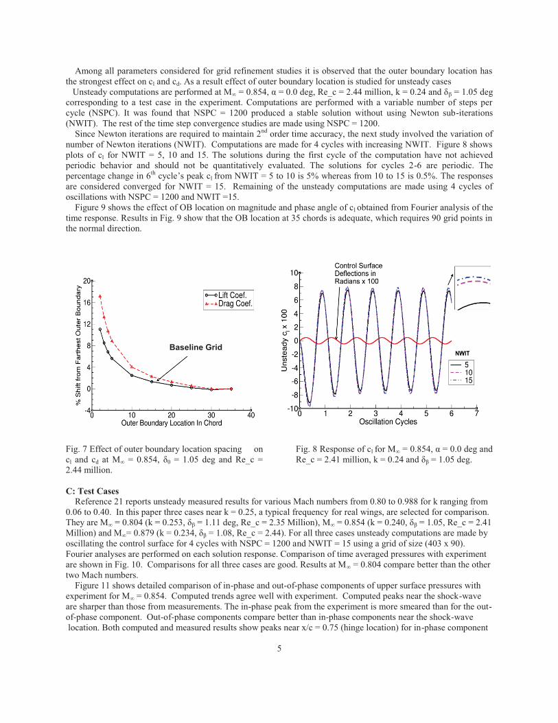
Among all parameters considered for grid refinement studies it is observed that the outer boundary location has the strongest effect on cl and cd. As a result effect of outer boundary location is studied for unsteady cases Unsteady computations are performed at M∞ = 0.854, α = 0.0 deg, Re_c = 2.44 million, k = 0.24 and δβ = 1.05 deg corresponding to a test case in the experiment. Computations are performed with a variable number of steps per cycle (NSPC). It was found that NSPC = 1200 produced a stable solution without using Newton sub-iterations (NWIT). The rest of the time step convergence studies are made using NSPC = 1200. Since Newton iterations are required to maintain 2nd order time accuracy, the next study involved the variation of number of Newton iterations (NWIT). Computations are made for 4 cycles with increasing NWIT. Figure 8 shows plots of cl for NWIT = 5, 10 and 15. The solutions during the first cycle of the computation have not achieved periodic behavior and should not be quantitatively evaluated. The solutions for cycles 2-6 are periodic. The percentage change in 6th cycle’s peak cl from NWIT = 5 to 10 is 5% whereas from 10 to 15 is 0.5%. The responses are considered converged for NWIT = 15. Remaining of the unsteady computations are made using 4 cycles of oscillations with NSPC = 1200 and NWIT =15. Figure 9 shows the effect of OB location on magnitude and phase angle of cl obtained from Fourier analysis of the time response. Results in Fig. 9 show that the OB location at 35 chords is adequate, which requires 90 grid points in the normal direction. Fig. 7 Effect of outer boundary location spacing on cl and cd at M∞ = 0.854, δ0 = 1.05 deg and Re_c = 2.44 million.
Fig. 8 Response of cl for M∞ = 0.854, α = 0.0 deg and Re_c = 2.41 million, k = 0.24 and δβ = 1.05 deg.
C: Test Cases Reference 21 reports unsteady measured results for various Mach numbers from 0.80 to 0.988 for k ranging from 0.06 to 0.40. In this paper three cases near k = 0.25, a typical frequency for real wings, are selected for comparison. They are M∞ = 0.804 (k = 0.253, δβ = 1.11 deg, Re_c = 2.35 Million), M∞ = 0.854 (k = 0.240, δβ = 1.05, Re_c = 2.41 Million) and M∞= 0.879 (k = 0.234, δβ = 1.08, Re_c = 2.44). For all three cases unsteady computations are made by oscillating the control surface for 4 cycles with NSPC = 1200 and NWIT = 15 using a grid of size (403 x 90). Fourier analyses are performed on each solution response. Comparison of time averaged pressures with experiment are shown in Fig. 10. Comparisons for all three cases are good. Results at M∞ = 0.804 compare better than the other two Mach numbers. Figure 11 shows detailed comparison of in-phase and out-of-phase components of upper surface pressures with experiment for M∞ = 0.854. Computed trends agree well with experiment. Computed peaks near the shock-wave are sharper than those from measurements. The in-phase peak from the experiment is more smeared than for the out-of-phase component. Out-of-phase components compare better than in-phase components near the shock-wave location. Both computed and measured results show peaks near x/c = 0.75 (hinge location) for in-phase component
5
Baseline Grid
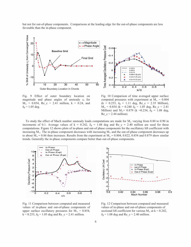
but not for out-of-phase components. Comparisons at the leading edge for the out-of-phase components are less favorable than the in-phase component. Fig. 9 Effect of outer boundary location on magnitude and phase angles of unsteady cl for M∞ = 0.854, Re_c = 2.41 million, k = 0.24, and δβ = 1.05 deg.
Fig. 10 Comparison of time averaged upper surface computed pressures with experiment at M∞ = 0.804 (k = 0.253, δβ = 1.11 deg, Re_c = 2.35 Million), M∞ = 0.854 (k = 0.240 δβ = 1.05 deg, Re_c = 2.41 Million) and M∞= 0.879 (k =0.234, δβ = 1.08 deg, Re_c = 2.44 million).
To study the effect of Mach number unsteady loads computations are made for M∞ varying from 0.80 to 0.90 in increments of 0.1. Average values of k = 0.242, δβ = 1.08 deg and Re_c = 2.40 million are used for these computations. Figure 12 shows plots of in-phase and out-of phase components for the oscillatory lift coefficient with increasing M∞. The in-phase component decreases with increasing M∞ and the out-of-phase component decreases up to about M∞ = 0.86 then increases. Results from the experiment at M∞ = 0.804, 0.822, 0.854 and 0.879 show similar trends. Generally the in-phase components compare better than out-of-phase components. Fig. 11 Comparison between computed and measured values of in-phase and out-of-phase components of upper surface oscillatory pressures for M∞ = 0.854, k = 0.253, δβ = 1.05 deg and Re_c = 2.41 million.
Fig. 12 Comparison between computed and measured values of in-phase and out-of-phase components of sectional lift coefficient for various M∞ at k = 0.242, δβ = 1.08 deg and Re_c = 2.40 million.
6
Baseline Grid
Outer Boundary Location in Chords
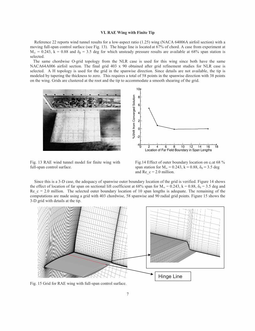
VI. RAE Wing with Finite Tip Reference 22 reports wind tunnel results for a low-aspect ratio (1.25) wing (NACA 64006A airfoil section) with a moving full-span control surface (see Fig. 13). The hinge line is located at 67% of chord. A case from experiment at M∞ = 0.243, k = 0.88 and δβ = 3.5 deg for which unsteady pressure results are available at 68% span station is selected. The same chordwise O-grid topology from the NLR case is used for this wing since both have the same NACA64A006 airfoil section. The final grid 403 x 90 obtained after grid refinement studies for NLR case is selected. A H topology is used for the grid in the spanwise direction. Since details are not available, the tip is modeled by tapering the thickness to zero. This requires a total of 58 points in the spanwise direction with 38 points on the wing. Grids are clustered at the root and the tip to accommodate a smooth shearing of the grid. Fig. 13 RAE wind tunnel model for finite wing with full-span control surface.
Fig.14 Effect of outer boundary location on cl at 68 % span station for M∞ = 0.243, k = 0.88, δ0 = 3.5 deg and Re_c = 2.0 million.
Since this is a 3-D case, the adequacy of spanwise outer boundary location of the grid is verified. Figure 14 shows the effect of location of far span on sectional lift coefficient at 68% span for M∞ = 0.243, k = 0.88, δ0 = 3.5 deg and Re_c = 2.0 million. The selected outer boundary location of 10 span lengths is adequate. The remaining of the computations are made using a grid with 403 chordwise, 58 spanwise and 90 radial grid points. Figure 15 shows the 3-D grid with details at the tip. Fig. 15 Grid for RAE wing with full-span control surface.
7
Hinge Line

To verify the adequacy of time step size, computations are made for increasing NSPC with NWIT = 15 at M∞ = 0.243, k = 0.88 and δβ = 3.5 deg. It is found that responses become periodic in 4 cycles. Figure 16 shows the effects of NSPC on in- and out-of-phase components of oscillatory cl at 68% span. Results converge at NSPC = 4800 where NWIT = 10 and 15 give almost identical results. Figure 17 shows the comparison of computed results with experiment for in-phase and out-of-phase components of upper surface oscillatory pressure. Both components compare well in trend with the experiment. In-phase components compare better than out-of-phase components. Differences near the leading edge are higher than along the rest of the chord. Similar differences in out-of-phase values are reported in Ref. 22 in which comparisons with the linear theory are made. It is noted that because of the low Mach number the out-of-phase values are significantly smaller than in-phase values.
Fig. 16 Effect of NSPC on in-phase values of oscillatory cl at 68% semi span for M∞ = 0.243, k = 0.88 and δβ = 3.5 deg.
Fig. 17 Comparison of upper surface oscillatory cp between computations and experiment at 68 % span for M∞ = 0.243, k = 0.88 and δβ = 3.5 deg.
V. Conclusions
Computations of the flows over full-span oscillating control surfaces are performed using the Reynolds-Averaged Navier-Stokes equations. An embedded sheared-grid approach in the context of a general purpose overset based CFD code is used to model the oscillating control surfaces. The procedure is validated by comparing unsteady pressures and integrated forces with experiments. Two test cases with the same airfoil section, one a wall-to wall mounted wing and another a finite-span cantilever wing, are considered. Grids are selected based on detailed grid refinement studies that involved effects of chordwise spacing, near surface spacing, near surface stretching factor and outer boundary locations. Steady computations show that results are more sensitive to outer boundary location than other parameters. Unsteady computations on finite tip wing need more steps per cycle than computations on 2D airfoil whereas the number of Newton sub-iterations is almost same for both. In general, in-phase components compared better with experiment than out-of-phase components. Moving control surface module developed for a general purpose CFD code will facilitate its application for analysis and design of active controls. The present method will be extended to model part-span control surfaces on parallel computers.
Acknowledgments
The author thanks Henry Lee of NASA Ames Research center for providing a script for the CGT grid tool to generate 2-D grids. Terry Holst, chief of Fundamental Modeling and Simulation Branch at NASA Ames Research Center and CFD lead of Rotary wing project, made valuable suggestions on grid refinement studies.
8
Number of Steps per Cycle x103
(NSPC)

References
1. Carey, B. “BAE Systems Develops Aircraft Active Controls Stick,” Aviation International News (AIN) Online, July 10, 2012. (http://www.ainonline.com/aviation-news/2012-07-10/bae-systems-develops-civil-aircraft-active-control-stick)
2. Lau, B., Obriecht, N., Gasow, T., Hagerty, B., Cheng, K. and Sim, B., “Boeing-SMART Test Report for DARPA Helicopter Quieting Program,” NASA TM 2010-216404, April 2010.
3. Maier, R., “Active Control for Blended Wing Body Aircraft,” Aerodays 2011, Madrid, March 2011. [www.cdti.es/recursos/doc/eventosCDTI/Aerodays2011/7G2.pdf, July 2012]
4. Mukhopadhyay, V., “Transonic Flutter Suppression Control Law Design, Analysis and Wind Tunnel Test Results,” 2nd International Conference on Nonlinear Problems in Aviation and Aerospace, Daytona Beach, FL, April 1998, pp. 45-51.
5. Guruswamy, G. P., “An Integrated Approach for Active Coupling of Structures and Fluids,” AIAA J., Vol. 27, No. 6, June 1989, pp. 788-793.
6. Poling, D. R., Dadone, L. and Telionis, D. P., “Blade-Vortex Interaction,” AIAA J., Vol. 27, No. 6, June 1989, pp. 694-699.
7. Guruswamy, G. P., “Vortical Flow Computations on a Flexible Blended Wing-Body Configuration,” AIAA J., Vol. 30, No. 10, Oct. 1992, pp. 2497-2503.
8. Guruswamy, G. P. and Tu, E. L., “Transonic Aeroelasticity of Fighter Wings with Active Control Surface,” J. of Aircraft, Vol. 26, No. 7, July 1989, pp. 682-684.
9. Bharadwaj, B. K., “Computation of Steady and Unsteady Control Surface Loads in Transonic Flow,” AIAA Paper 90-0935, 1990.
10. Obayashi, S. and Guruswamy, G. P., “Navier-Stokes Computations for Oscillating Control Surfaces,” J. of Aircraft, Vol. 31, No. 3, May-June 1994, pp. 631-636.
11. Klopfer, G. H. and Obayashi, S., “Virtual Zone Navier-Stokes Computations for Oscillating Control Surfaces,” AIAA Paper 93-3363, 11th AIAA Computational Fluid Dynamics Conference, Orlando, FL, July 1993.
12. Rampurawala, A. and Badcock, K. J., “Treatment of Forced Flap Motions for Aeroelastic Simulations of an Arrow wing,” AIAA Paper 2005-4962, 23rd AIAA Applied Aerodynamics Conference, June 2005.
13. Guruswamy, G. P., “User's Guide for ENSAERO-A Multidisciplinary Program for Fluid/Structural/Control Interaction Studies of Aircraft,” NASA TM 108853, Oct. 1994.
14. Yeh, D. T., “Aeroelastic Analysis of a Hinged-Flap and Control Surface Effectiveness Using the Navier-Stokes Equations," AIAA Paper 95-02263, 1995.
15. Obayashi, S., Chiu, I. and Guruswamy, G. P., “Navier-Stokes Computations on Full-Span Wing-Body Configuration with Oscillating Control Surfaces,” AIAA J., Vol. 32, No. 6, Nov.-Dec. 1995, pp. 1227-1233.
16. Byun, C. and Guruswamy, G. P., “Aeroelastic Computations on Wing-Body-Control Configurations on Parallel computers,” AIAA Paper 96-1389, Structural Dynamics Conference, Salt Lake City, UT, April 1996.
17. Guruswamy, G. P., “HiMAP: A Portable Super Modular Multilevel Parallel Multidisciplinary Process for Large Scale Analysis,” Advances in Engineering Software, Elsevier, Vol. 31, Oct. 2000, pp. 617-620.
18. Nichols, R. H., Tramel R. W. and Buning P. G., “Solver and Turbulence Model Upgrades to OVERFLOW2 for Unsteady and High-Speed Applications,” AIAA Paper 2006-2824, AIAA 36th Fluid Dynamics Conference, San Francisco, CA, June 2006.
19. Rogers, S. E., Roth, K. and Nash, S. M., “CFD Validation of High-Lift Flow with Significant Wind-Tunnel Effects,” AIAA Paper 2000-4218, 18th Applied Aerodynamics Conf., Denver, CO, August 2000.
20. Potsdam, M., Fulton, M. V. and Dimanlig, A., “Multidisciplinary CFD/CSD Analysis of the SMART Active Flap Rotor,” Proceedings of the 66th Annual Forum of the American Helicopter Society, Phoenix, Arizona, May 2011.
21. Zwann, R. J., “NACA 64006 Oscillating Flap-Compendium of Unsteady Aerodynamic Measurements,” AGARD-R-702, Aug. 1982.
22. Drane, D. A., “Measurements in Low-Speed Flow of Unsteady Pressure Distributions on a Rectangular Wing with an Oscillating Control Surface,” R& M No. 3763, Royal Aeronautical Establishment, London, 1976.
9
23. Jain , R., Yeo, H. and Chopra, I., “Investigation of Trailing-edge Flap Gap Effects on Rotor Performance Using High-Fidelity Analysis,” J. of Aircraft, Vol. 50, No. 1, Jan.-Feb. 2013, pp. 140-150.
24. Liggett, N. and Smith, M. “Study of Gap Physics of Airfoils with Unsteady Flaps,” J. of Aircraft, Vol. 50, No. 2, March–April 2013, pp. 643-650.
25. Liu, L., Padthe, A., Friedmann, P. P., Quon, E. and Smith, M., “Unsteady Aerodynamics of an Airfoil/Flap Combination on a Helicopter Rotor Using CFD and Approximate Methods,” J. of the American Helicopter Society, Vol. 56, No. 3, July 2011, pp. 032003-1-032003-13.
26. Peyret, R. and Viviand, H., “Computation of Viscous Compressible Flows based on Navier-Stokes Equations,” AGARD-AG-212, 1975.
27. Pulliam, T. H. and Chaussee, D. S., “A Diagonal Form of an Implicit Approximate-Factorization Algorithm,” J. of Computational Physics, Vol. 39, No. 2, 1981, pp. 347-363.
28. Spalart, P. R., “Direct Simulation of a Turbulent Boundary Layer,” J. of Fluid Mechanics, Cambridge University Press, 1988, 187, pp. 61-98.
29. Kreyszig, E., “Fourier Analysis,” Advanced Engineering Mathematics, John Wiley & Sons, Inc., Hoboken, NJ, 1976, pp. 478- 529.
30. Chan, W. M., “Developments in Strategies and Software Tools for Overset Structured Grid Generation and Connectivity,” AIAA Paper 2011-3051, 20th AIAA Computational Fluid Dynamics Conference, June 2011, Honolulu, Hawaii.
10