computer-aided mapping systems:the next generation
TRANSCRIPT

Computer-Aided Mapping Systems: The Next Generation ]. Raul Ramirez Center for Mapping, The Ohio State University, Columbus, OH 43212
ABSTRACT: For the last two decades Digital Mapping Systems (DMS) have been used in production environment by the mapping community with different degrees of success. Advances in the computer field in the last few years are reflected in improved, faster, less expensive, and easier-to-use computers with improved graphic capabilities. Also, during this period a wide variety of Computer-Aided Drafting (CAD) packages for the PC environment have been developed. These advances, the experiences gained thus far by the mapping community in the production of digital topographic maps, and the increased use of Geographic Information Systems (GIs) require the rethinking of the scope and purpose of many DMS. The time has arrived for the development of the next generation of these systems. This paper describes the design of the Universal Computer-Aided Mapping System (UCAMS). UCAMS is part of this new generation of DMS.
INTRODUCTION
T HE FIRST GENERATION of Digital Mapping Systems (DMS) was introduced to the mapping community in the early 1970s.
They were a tool to increase the production of conventional hard-copy topographic maps. The main components - hard- ware and software-were designed to be interfaced to analog photogrammetric instruments equipped with three encoders. Later, there were interfaces to analytical plotters (Ramirez, 1988~). The most important hardware components were a minicom- puter, an alphanumeric terminal, an electronic interface, one or several pedals, and an electronic plotting table. The most im- portant software components were photogrammetric and car- tographic programs designed to assist the photogrammetric operator in repetitive operations.
As indicated earlier, the purpose of these systems was to help in the production of conventional maps. These systems assisted in squaring corners of buildings and in drawing cartographic points and special lines. They placed index contour labels and drew and labeled spot elevations. This was done under com- puter control as part of data collection. However, there were no editing capabilities in the early DMS; any corrections on the hard-copy maps were done in the conventional, manual way by drafting personnel.
The second generation of DMS was introduced to the mapping community at the beginning of the 1980s (Ramirez, 1988~). The major differences were the substitution of the electronic plotting table by a graphic terminal as the output device during data collection and the use of drum plotters for hardcopies. These systems included off-line and sometimes on-line computer-con- troller editing capabilities.
New hardware was added to the second generation of DMS, which included the graphic terminal and its controller, a digi- tizing surface, and an input digitizing device. New software included a computer-aided design (CAD) package for digital drafting and editing, database routines for the storage and re- trieval of data, and translators for data exchange. All the CAD packages and their databases were specialized packages devel- oped by the DMS designers, and only map-related functions were implemented as part of them.
The third generation of DMS was introduced in the second half of the 1980s (Rarnirez, 1988~). Major differences were the replacement of minicomputers by personal computers (PC) and specialized CAD packages by commercial ones. For the first time, these systems used computers, graphic screens, graphic boards, and digitizing tablets from a variety of manufacturers. The use of PCS is the result of the advances in computer technology.
These advances are reflected in the PC's higher speed, memory capacity, disk storage, networking capabilities, and low price. Their use and the use of faster and improved graphic boards and screens have opened the door for the design of improved and inexpensive DMS.
Finally, the use of commercial CAD packages and their data- bases is the result of the experience accumulated in the past five years in the production of digital topographic mapping in the United States. Today, the de facto standard format for digital topographic products are Autodesk's AUTOCAD and Inter- graph's IGDS. These standards, together with the development of these CAD packages for PC's, have eliminated the need of specialized CADS.
Even though the last generation of DMS is an enormous im- provement with respect to the previous one, it still has many shortcomings, such as its database format dependency and long training period. In the next section, Universal Computer-Aided Mapping System (UCAMS), a member of the fourth generation of CAMS, is described in detail. Its design incorporates the new technologies as well as original solutions to some of the most common problems found in previous systems. A major effort has also been made in designing a "user friendly" system.
UNIVERSAL COMPUTER-AIDED MAPPING SYSTEMS
A universal computer-aided mapping system (UCAMS) is com- posed by two modules: the Photogrammetric And Mapping (PAM) module and the Drafting And Editing (DAE) module. The PAM module consists of a set of computer programs that allows def- inition of the characteristics of a mapping project and the col- lection of data. The DAE module allows map display and editing during and after data collection, storage and retrieval of data, and generation of hard-copies.
The PAM and the DAE modules are described in the following paragraphs. The PAM module is the heart of UCAMS and it con- tains the elements which are unique to the fourth generation of DMS. A detailed description of its components is presented in this paper, while the DAE module is described in a general manner.
THE UCAMS PHOTOGRAMMETRIC AND MAPPING MODULE
The PAM module is composed by two sub-modules: the Basic Operations (BO) sub-module and the Complementary Opera- tions (CO) sub-module.
The BO sub-module includes the following tasks: Ground control file generation/modification
PHOTOGRAMMETRIC ENGINEERING & REMOTE SENSING, Vol. 57, No. 1, January 1991, pp. 85-88. 01991 American Society for Photogrammetry
and Remote Sensing
PHOTOGRAMMETRIC ENGINEERING & REMOTE SENSING, 1991
Camera file generatiodmodification Proiect definitiodmodification ~ttkbute definitiodmodification Symbol and Line Library generatiodrnodification Photogrammetric model setup Photogrammetric model data collection Photogrammetric model ties generation
Each one of these tasks allows consistent generation and manipulation of specific types of data. This consistency is very important from the point of view of data quality. On the other hand, these tasks are time-saving tools. A brief description of them follows.
This is an optional task that allows the design of customized cartographic points and lines by the mapper. The design can be done by means of a keyboard or digitizing surface. Three different types of graphic elements can be designed: cartographic points, line types, and line symbols. Cartographic points are symbols; their position in the terrain is defined by a single point and sometimes by a direction. Line types are linear patterns along the path of a line. Line symbols are non-linear patterns along the path. These non-linear patterns run along and outside the path of the line.
Editing of the symbol and line library includes deletion, addition, and modification of cartographic points and patterns.
This task provides the user of UCAMS the capability to create PHOTOGRAMMETRIC MODEL SETUP TASK and manip;late ground control information*nece&ary for a mapping project. The user could generate the UCAMS ground control file from a triangulation file or by typing the information into the computer. Control information includes control point D, planimetric and elevation values, types of control (horizontal, vertical, full, etc.), and data accuracy. Manipulation of the information includes deletion, change, and addition of data.
This task handles the photogrammetric camera information for the setup of models when analytical plotters are used. It is not used with analog photogrammetric instruments. Data are entered from the keyboard and stored in a computer file from which it can be retrieved. Data can then be added, deleted, and changed.
This task is used to set and modify the parameters of a mapping project. There are two group of parameters: common parameters and specific parameters. Common parameters are those which are used throughout the entire project. Examples of these are a project ID, ground control file, camera file, attribute file, symbol and line library, map scale, and contour interval. Specific parameters change from time to time in the development of a project. Some examples are operator name, photogrammetric model ID, and model area limits.
This task customizes each mapping project by allowing the selection of the drafting components and their attributes for each group of cartographic features.
Drafting components are the cartographic alphabet symbols and the alphanumeric characters used in the representation of cartographic features. Cartographic features are the objects represented in a map. Some examples of these features are houses, roads, side-walks, individual trees, and tree-lines.
Any feature of a topographic map can be represented by one or more characters of the cartographic alphabet (Ramirez, 1988a, 1988b). The cartographic alphabet is composed of four basic symbols: point, line, curve, and blank space. These symbols, together with the signs of the natural language, numerical language, and cartographic operations, constitute the CARTOGRAPHIC LANGUAGE. Hence, the characters to be used in the collection of each group of map features are known to the mapper and are defined by this task.
Cartographic attributes are defined by Bertin's (1983) VISUAL VARIABLES. They are the three space dimensions, size, value, texture, color, orientation, and shape of any map feature. All but the space dimensions are known before a mapping project is executed, and they are defined by the mapper using this task.
Editing of the attribute file includes deletion, addition, and modification of the components or characteristics of a feature.
This task performs the set-up of photogrammetric models, including interior, relative, and absolute orientations for analytical plotters. Only relative and absolute orientations are performed for analog instruments.
Interior orientation requires observation of a minimum of four fiducial marks per photo. Observations can be done clockwise or counter-clockwise. Relative orientation requires a minimum of five stereo-points. These points must be ldcated close to the conventional von Gruber points. For absolute orientation, a minimum of two horizontal and three vertical control points are needed. This task includes options to eliminate observed points from the computation, to re-observe points, and to repeat the orientation observations and computations.
This task allows compilation of a map from a photogrammetric model. This includes selection from the attribute file of map features, their collection, and the interface with the CAD package.
This task allows for extracting and copying selected areas of a digital topographic map into another digital file. Usually this task is executed before a new model, surrounded by previously collected models, is collected. This task transfers or copies a narrow strip of the adjacent models into the file of the model to be collected.
All the components of the Basic Operations (80) sub-module described in the previous paragraphs are considered standard components of UCAMS. They are part of the basic software package. In the following paragraphs, the other major component of the PAM module- the Complementary Operations (CO) sub- module- is described.
The CO sub-module includes all those tasks which allow an improved, faster, and simpler digital topographic map production and map use, as well as those tasks which make the topographic data proper for GIS use. In general, all of its tasks are optional. The following is a list of some of these tasks but, due to space limitations, they are not described in this paper:
Interactive or batch contour interpolation Interactive or batch contour smoothing Interactive or batch index contour labeling Interactive or batch index contour selection Interactive or batch cross-hatching and area uattemina Interactive or batch feature matchg
- Interactive or batch feature cleaning Feature connection and geometry Gmplification Interactive and batch model cutting and merging Interactive or batch information level merging Interactive or batch information level splitting Interactive or batch marginal map information generation Interactive or batch polygon manipulation
COMPUTER AIDED MAPPING SYSTEMS
Profile data collection Volume computation Cross-section data collection Cross-section generation and manipulation
Some of these tasks must be run after data collection is completed and before interactive editing is performed. In the next section, the other major component of UCAMS, the Interactive Editing Module (CAD), is described.
THE DRAFTING AND EDITING MODULE
The Drafting and Editing Module (DAE) is the set of computer programs that allows the drafting and the editing of the map. For example, in UCAMS the DAE module is any PC-based com- mercial CAD package. Studies done by Ramirez (1988a) show that only a very small set of graphic commands are used in the drafting of any topographic map. All or most of those com- mands exist in any commercial CAD package, and this explains why they can be used with UCAMS.
The CAD package is used during data collection to display in real-time the cartographic features collected and to retrieve and store data in the CAD'S database. It is also used to correct the map during data collection by using the CAD'S editing capabil- ities. The CAD package is used after data collection to edit and to complete the map compiled from each model, to assemble each map sheet, and to produce hard copies.
UCAMS does not use direct CAD commands because most of them are not appropriate for mapping. Instead, UCAM.5 has a set of cartographic instructions which combines those com- mands into cartographic-like operations. These UCms instruc- tions are generated from the Universal Mapping Commands.
THE UNIVERSAL MAPPING COMMANDS
In UCAMS, the communication between the PAM and the DAE module is achieved by the Universal Mapping Commands (UhfC) and the cartographic dictionary. The UMC are commands that allow, regardless of the specific CAD system, the issuance of CAD-related instructions in consistent form. This is a very im- portant characteristic of any fourth-generation DMS. The UMC are defined from the Universal CAD Language (UCADL) (Rami- rez, 1988b) which is the language used in the generation of the attribute file.
The UCADL is constituted by the cartographic alphabet (pre- viously discussed) and the set of construction rules governing the combination and appearance of the alphabet signs in each map feature. The construction rules or grammar include the cartographic operations and the cartographiJnon-cartographic restrictions (Ramirez, 1988a, 1988b).
The cartographic operations are concatenation, image con- struction, addition, and coordinate transformation. The carto- graphichon-cartographic restrictions are of two types: alphabet character restrictions and cartographic feature restrictions. All non-cartographic restrictions are of the second type.
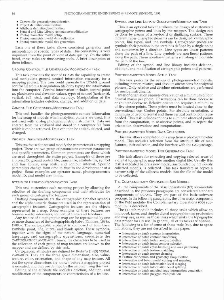
Concatenation ( K ) (Figure 1) is the operation which allows the connection of two alphabet characters (PRIMES) to generate a more complex shape called an ELEMENT. Concatenation also allows the combination of two ELEMENTS to generate an even more complex shape.
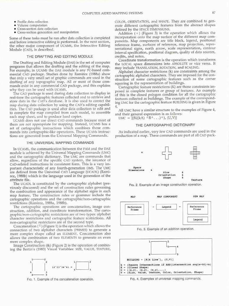
Image Construction (&) (Figure 2) is the operation of combin- ing the Bertin's (1983) Visual Variables: SIZE, VALUE, TEXTURE,
FIG. 1 . Example of the concatenation operation.
COLOR, ORIENTATION, and SHAPE. They are combined to gen- erate different cartographic features from the abstract shapes defined by the SPACE DIMENSIONS.
Addition (+) (Figure 3) is the operation which allows the incorporation onto the map surface of the different map com- ponents. Map components are title block, legend, positional reference frame, surfaces of reference, map projection, repre- sentational signs, north arrow, scale representation, contour interval specification, positional diagram, quality of data sources, credits, and notes.
Coordinate transformation is the operation which transforms the LOCAL space dimensions into ABSOLUTE or vice versa. It may include TRANSLATION, ROTATION, and SCALING.
Alphabet character restrictions (k) are constraints among the cartographic alphabet characters. They are imposed for the con- struction of some cartographic features such as the corner squaring in the representation of buildings.
Cartographic feature restrictions (K) are those constraints im- posed in complete features or group of features. An example of this is the closed polygon condition for all the cartographic features collected as buildings. The example of the correspond- ing UMC for the cartographic feature BUILDING is given in Figure 4.
All UMC have a similar structure to the examples of Figure 4, and their general expression is as follows:
UMC = [(K((kA) A B A . . .) A ) , {U,V}]
THE CARTOGRAPHIC DICTIONARY
As indicated earlier, very few CAD commands are used in the production of a map. Thefje commands are part of all CAD pack-
Space Dimensions
Size & Orientation &
Shape & Texture
FIG. 2. Example of an image construction operation.
Frame Frame
FIG. 3. Example of an addition operation.
r;-, 6 5
BUILDING = [X(k Line-), (U,V)]
k - (Square Intersections if AES(intersecti0n angle-90)<m) K - (Closed Shape) u = ((X,Y), (X,Y), (X.Y),...) V = (Size, Value, Texture, Color, Orientation, Shape)
FIG. 4. Examples of universal mapping commands.

PHOTOGRAMMETRIC ENGINEERING & REMOTE SENSING, 1991
ages. They have different degrees of efficiency and their use varies from one CAD to another.
The cartographic dictionary is the part of UCAMs that takes care of transforming the universal mapping commands to each specific CAD language. This is done by looking at a CAD table for the equivalent UCAMS element. The CAD table is built for each CAD package. To simplify the CAD tables, many functions are implemented as part of UCAMS. Examples of this are data filtering and corner squaring. On the other hand, U C M S has all the functions required to generate a map except the editing capabilities. Hence, UCMs can be interfaced to basically any- one, regardless of the options of the CAD.
To achieve the maximum efficiency in communication be- tween the PAM and DAE modules, all the data-intensive CAD commands may be used instead of UCAMS. For example, symbol generation may be most efficient if CAD commands are used. This minimizes the data exchange between both modules. Con- versely, the mapper could use these UCAMS capabilities to gen- erate elements not present in CAD packages. UCAMS allows the user to choose the editing menu: the UCAMS menu or the CAD menu. The UCAMS menu only includes mapping functions and it is the same regardless of the CAD system. When this option is selected, a more elaborate cartographic dictionary is gener- ated.
CONCLUSIONS
to solve some of the traditional problems found in the field of digital topographic map production. The PC-based system al- lows the use of faster computers with improved graphic capa- bilities and the use of different commercial CAD packages which solve or minimize the problem of data exchange for topographic maps. The use of a unique set of commands, regardless of the CAD package, decreases the training period. These character- istics, together with the complementary tasks, make any fourth- generation DMS a cost-efficient system for the production of digital topographic maps.
ACKNOWLEDGMENT
UCAMS is the Digital Mapping System developed by Sysgraph Inc., of Reynoldsburg, Ohio.
REFERENCES
Bertin, J., 1983. Semiology of Graphics: Diagrams, Networks, aild Maps, The University of Wisconsin Press, Madison.
Ramirez, J. R., 1988a. A Map Representation Theory for the Eval~lation of Digital Exchange Formats, Report No. 389, Department of Geodetic Science and Surveying, The Ohio State University.
-, 1988b. A Cartographic Lnizgunge for a Uiziversal Computer-Aided Mappiizg Systenz (UCAMS), Internal Report, SysGraph, Inc.
-, 1988c. A Photogrnminetrist's Guide to Digital Mapping, Part I: C/~oosiilg the Right Systenl, Special Publication No. 1, SysGraph, Inc.
The Universal Computer-Aided Mapping System (UCAMS) is an example of the new generation of DMS. UCAMS is designed (Received 22 May 1989; revised and accepted 23 May 1990)
2
Certificate in Air Survey Photography University College London
Department of Photogrammetry and Surveying
22 April to 16 August 1991
The Department of Photogrammetry and Surveying at University College London is offering a new Cmonth course in aerial photography designed to prepare personnel for a career in air survey and leading to a UCL Certificate in air Survey Photography. The main objectives of the course are to introduce students to air survey photography and to provide training in the acquisition of primary data.
Part 1: 22 April t o 15 July 1991 Introduction Introduction to Aerial Photography Introduction to Aerial Photogrammetry Photogrammetry:
Theory and Exercises Cartography Aviation Survey Flight and Navigation Photographic Theory
Part 2: 22 July to 16 August 1991 Ground Studies Survey In-flight Studies Post-flight Procedures
Student Entry Requirements Proficiency in the English language Education to University entrance level in mathmatics and physical sciences
Medically fit for flying and have normal color vision
For further information, contact: Elizabeth Royston UCLi 5 Gower Street London WC1 E 6HA, U.K. tel. no. 071 636 7668 FAX 071 637 7921.