computer-based aids for pressure relief contingency assessment · the coolant pressure. all too...
TRANSCRIPT

COMPUTER-BASED AIDS FOR PRESSURE RELIEF CONTINGENCY ASSESSMENT
R K Tanner, Department of Chemical and Process Engineering, Heriot-Watt University
Assessing relief contingencies is the most difficult task in pressure relief design and the techniques involved are not well described in the literature. Computer-based aids have been developed for identifying and quantifying contingencies. The advantages of these aids are in providing assistance to engineers not expert in the field and in allowing contingencies to be recognised, quantified and possibly eliminated early in the design process.
Pressure relief Overpressure Underpressure Expert system Computer-based aids
INTRODUCTION
Pressure relief is an important aspect of process design. It needs to be considered whenever there is the possibility of operation above (known as "overpressure") or below ("underpressure") allowable equipment working pressures. If changes to operating conditions or equipment design are impractical, then a relief system is necessary to eliminate the potential for equipment rupture and release of hazardous materials.
Six stages to pressure relief design can be identified : 1. Division of the process into sections (known as "isolatable systems"), each
of which can become isolated through valve closure or line blockage and consequently exposed to pressures outside the allowable limits;
2. Identification and quantification of potential causes of overpressure and underpressure, known as the relief "contingencies";
3. Selection of the appropriate relief device, normally either a relief valve or bursting disc;
4. Sizing of the relief device to handle the necessary relief flow rate to avoid the hazardous condition;
5. Design of the pipework associated with the relief device; 6. Disposal of the relieved fluids.
Stage 1 follows from a careful analysis of the process flow sheet. There are well established guidelines for stages 3, 5 and 6. Stage 4, sizing of the relief device, is straightforward for single phase relief; sizing for a two-phase relief is more difficult but there are several researchers such as Morris (1) who are working in this area and developing design methods.
The most difficult task is stage 2, contingency assessment. There are many potential contingencies and all need to be identified. For instance overpressure can be a result of inflow from a high pressure source, heat input causing either thermal expansion, an increase in vapour pressure or vapour generation, or due to heat generation resulting from a chemical reaction. Correspondingly, underpressure can be due to outflow from the equipment, heat removal or heat absorption due to a reaction. The required relief flow,
467

I CHEM E SYMPOSIUM SERIES No. 134
whether it be vapour, liquid or two-phase, needs to be calculated for each contingency and the relief device sized for the greatest flow.
Considering the importance of relief contingency assessment in process design, the topic is surprisingly poorly described in the literature. Process safety texts such as those by Lees (2) and Wells (3) describe some of the more common contingencies but are not sufficiently comprehensive to act as a design guide, although Parry's recent book dedicated to pressure relief design (4) does cover the subject more thoroughly. The most detailed references are the American Petroleum Institute (API) publications; Recommended Practices 520 (5) and 521 (6) together with Standard 2000 (7) for storage tank relief. As with most design codes, these can be difficult to follow unless one is already familiar with them. Many larger companies have their own design guides, often based on the API codes but incorporating in-house expertise, but these can be so comprehensive as to be unwieldy.
There is a need for further design aids to help systematically identify and quantify relief contingencies, and this paper describes some computer-based aids developed at Heriot-Watt University. Pressure relief design has previously been suggested as an appropriate application for an expert system by Bunn and Lees (8) and a recent Annual Report by the Health and Safety Commission (9) highlighted the development of aids of this type as an area of particular interest to increase efficiency and retain in-house experience.
Although an expert system is being developed by an HSE/industry consortium to help relief sizing for explosions (10), the author is unaware of any available software for the more common case when the pressure rise is less rapid. This is surprising considering the number of packages available for other aspects of process safety, such as HAZOP-PC for documenting Hazard and Operability Studies (11) and SAFETI for carrying out Hazard Analysis (12).
DESCRIPTION OF THE DEVELOPMENTS
These development have been carried out using two PC based programming tools, one running on DOS [Crystal (13)] and the other on Windows [KnowledgePro Windows (14)]. They both incorporate a largely syntax free programming language which allow advisory systems of the type described to be relatively easily developed. The developments fall into three categories :
L On-line Design Guide
An on-line design guide, if well structured and incorporating good help facilities, can be much more user-friendly than the traditional "paper" version, providing rapid access to the required information. There are also some specific advantages of an on-line design guide for relief contingency assessment : 1. By helping the user to approach the design in a systematic way, it can
ensure that all potential overpressure and underpressure contingencies are identified. Wilday (15) emphasises the importance of ensuring all contingencies are identified in pressure relief design.
2. Relief design is a discipline which is regularly refined as a result of
468

I CHEM E SYMPOSIUM SERIES No. 134
operating experience. This is demonstrated by Fitt's description of ICI's relief design practices (16). If die software is well structured, changes can be easily incorporated. Furthermore if it is based on a main-frame computer, one can ensure that me most up-to-date methods are used throughout the company.
To demonstrate the potential of an on-line design guide, one has been developed to assist wim the assessment of pressure relief contingencies for storage vessels. Built-in expertise is accessed through user responses to simple questions. This allows the relevant contingencies to be identified and the appropriate means of quantification to be recommended for each.
Several types of storage vessel can be identified; atmospheric storage for liquids held at a temperature below their normal boiling point, pressurised or refrigerated storage for liquefied gases, and gas storage. For each type, there are many possible variables in the design. For instance the vessel may be spherical or cylindrical, it may have a fixed or floating roof and there may be a means of heating or cooling the contents. However all potential contingencies can be conveniently divided into a number of categories. This categorisation for overpressure in liquid storage vessels is shown in Figure 1. Conditions under which the contingencies can be eliminated are shown on the right-hand side of this Figure. This may result from the inherent tank design (eg tank able to withstand maximum upstream pressure) or due to control measures (eg high level trip does not allow tank to become liquid full).
Figure 2 demonstrates tiiis design guide in use. The top half of this Figure lists the questions asked and the responses from the user. In the example illustrated, the first seven questions are intended to allow contingencies to be eimer ruled in or out. For instance from the user responses to the first two questions, the built-in expertise eliminates rollover as a contingency because the vessel is not refrigerated and eliminates overpressure due to inflow of a heating medium because the tank is not heated.
The last two questions allow appropriate advice to be given once the relevant contingencies have been identified. All the questions require either a simple yes/no input or the selection of a single response from a list, and there is a help screen associated with each question to aid the user. The final summary screen for this example is shown in the bottom half of Figure 2. The methods for quantifying the contingencies are only summarised but the source of the information is given in case the user wants further guidance.
2. An Aid for Relief System Synthesis
As with storage vessels, generic over- and underpressure contingencies can be identified for other items of process equipment. For instance vapour relief is necessary to handle overpressure due to loss of reflux in a distillation column whilst liquid relief may be needed to protect against the effects of thermal expansion of the contents of totally liquid filled equipment.
In practice, the isolatable system may well be a combination of several items of equipment rather than a single item. An aid has been developed to allow relief contingencies to be identified based on the components of the isolatable system together with expert questioning specific to those
469

I CHEM E SYMPOSIUM SERIES No. 134
components. A previous development by Niida et al (17) identifies contingencies from user responses but takes no account of the composition of the isolatable system and therefore the questioning has to be more extensive.
Figure 3 shows two successive screens illustrating how the user builds up the isolatable system. The items of equipment are chosen in the order they occur in the isolatable system by locating the cursor over a graphical representation of each, as shown in the top half of figure 3. The more common items of process equipment are included, namely pump/compressor, heat exchanger, storage vessel, separating column and reactor. All "new input lines" to the system are included as these are also potential high pressure sources. Once the items have been selected, the isolatable system is displayed as shown in the bottom half of figure 3. For the example illustrated, this system consists of a reactor with two input lines, pre-cooling and pump discharge. Editing facilities allow the system to be easily changed or extended.
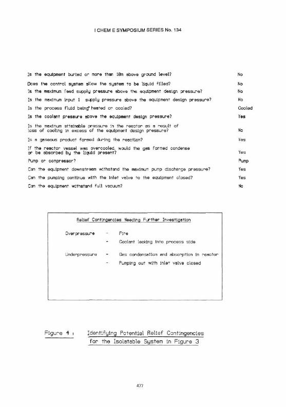
The user is asked a number of questions based upon the composition of the isolatable system. The top half of Figure 4 lists the questions and user responses for the system in Figure 3. The questioning depends upon the items of equipment involved (eg whether the exchanger is a heater or cooler) as well as any interactions between these items (eg whether a loss of cooling results in a pressure in the reactor in excess of the design pressure). The first two questions are designed to rule in or out fire relief and liquid thermal expansion as possible contingencies. The bottom half of Figure 4 shows the final summary screen for this example, listing the appropriate overpressure and underpressure contingencies.
A tool of this type is particularly valuable early in the design process when it is relatively easy to design out contingencies or to make changes that can reduce the relief load. For instance in the example illustrated, knowing that one of the overpressure contingencies is coolant flowing into the process side, then the process side design pressure could be increased to withstand the coolant pressure. All too often relief design is carried out late in the design process when changes to reduce relief load are difficult if not impossible.
3. Calculation Tool
To develop a tool for quantifying pressure relief contingencies is an ambitious undertaking due to the complexity of many of the calculations involved [for instance those developed by DIERS for reactor relief (18)] and the need for physical property data applicable at the relief conditions. However, such a tool can be a powerful design aid. To demonstrate this potential, a system has been developed for quantifying the contingencies for pressure relief on the shell side of a shell and tube heat exchanger. Assuming that the shell can withstand the maximum upstream shell side pressure, three major overpressure contingencies can be identified :
a. Tube Rupture This contingency must be considered if the tube side pressure exceeds the shell side design pressure. The system developed calculates the flow rate from the tube side into the shell assuming single phase liquid or gas flow, depending upon the condition of the tube side fluid.
470
I CHEM E SYMPOSIUM SERIES No. 134
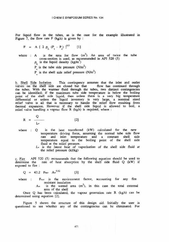
For liquid flow in the tubes, as is the case for the example illustrated in Figure 7, the flow rate F (kg/s) is given by :
where :
b. Shell Side Isolation This contingency assumes that the inlet and outlet valves on the shell side are closed but that flow has continued through the tubes. With the warmer fluid through the tubes, two distinct contingencies can be identified; if the maximum tube side temperature is below the boiling point of the shell side liquid, then unless there is a very big temperature differential or unless the liquid inventory is very large, a nominal sized relief valve is all that is necessary to handle the relief flow resulting from thermal expansion. However if the shell side liquid is allowed to boil, a relief valve handling a vapour flow R (kg/s) is required, where :
where : is the heat transferred (kW) calculated for the new temperature driving force, assuming the normal tube side flow rate and inlet temperature and a constant shell side temperature equal to the boiling point of the shell side fluid at the relief pressure. is the latent heat of vaporisation of the shell side fluid at
the relief pressure (kJ/kg)
c. Fire API 520 (5) recommends that the following equation should be used to determine the rate of heat absorption by the shell side fluid Q (kW) if exposed to fire :
Once Q has been calculated, the vapour generation rate R (kg/s) can be determined using equation [2].
Figure 5 shows the structure of this design aid. Initially the user is questioned to see whether any of the contingencies can be eliminated. For
471

I CHEM E SYMPOSIUM SERIES No. 134
instance, if the shell side design pressure is greater than the tube side pressure, contingency SL does not need to be considered and the amount of data that the user needs to enter is appropriately reduced.
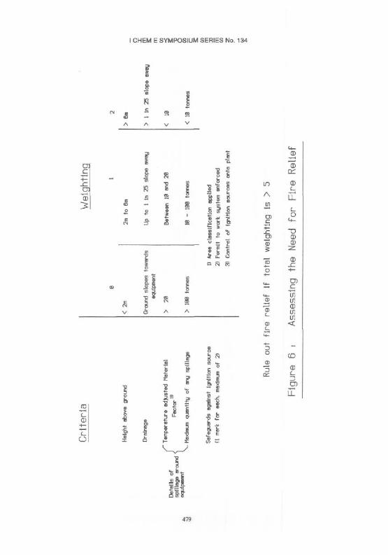
Fire relief is often the governing contingency; that is the one resulting in the maximum required relieving rate and therefore on which the relief device is sized. However, there are circumstances under which fire relief can be ruled out. It is generally eliminated as a contingency when the equipment is buried or well above ground level. A number of other factors affect the likelihood of overpressure due to a fire; these include the quantity and flammibility of any release in the vicinity that could fuel the fire, drainage around the equipment and precautions taken to avoid an ignition source. A method has been incorporated to quantify these factors in order to assess the need for fire relief. The basis of this method is shown in Figure 6.
Figure 7 shows the output from the system for the exchanger illustrated. The relief rates associated with each contingency are presented in tabular form. The advantage of this type of aid is the ability to recalculate the relief load for changes in the design variables; variables can be changed as shown in the left-hand screen, and after inputting any revised physical property data that is needed, the new relief rates are calculated as shown in the right-hand screen. For the example illustrated, the load has been recalculated for an increased shell side relief pressure, the addition of fire resistant insulation and an increased tube side flow.
As with the system described in Z above, an aid of this type is valuable early in the design process, for instance to assess ways of reducing the necessary size of the relief stream disposal system. It is also useful when plant modifications are considered, to check for any changes to necessary relieving rates, as illustrated by the significant increase required by increasing the octane flow to 20 kg/s for the example in Figure 7.
CONCLUDING REMARKS
Pressure relief contingency assessment is relatively poorly described in the literature and is therefore a potential area of development for computer-based aids. On-line design guides of the type described in 1. are particularly useful for engineers not expert in contingency assessment as they are very user-friendly.
The developments described in 2. and 3. for relief system synthesis and contingency quantification are important for demonstrating the potential of such aids. A logical future step would be an attempt to incorporate aids of this type into flowsheeting simulation packages where the detailed flowsheet, operating conditions and physical property data are already available. This would allow full relief assessment to be carried out in parallel with the main process design.
ACKNOWLEDGEMENTS
The author would like to thank George Greiss, Steven Mitchell, Grant Newberry, Douglas Reid and Robert Venables for their help in developing these aids during their undergraduate studies and likewise Ronan Flanagan during his MSc
472

I CHEM E SYMPOSIUM SERIES No. 134
studies. The co-operation of staff at Exxon at Mossmorran and Zeneca at Grangemouth is also appreciated.
REFERENCES
1. Morris,S.D.,1990,J Loss Prev Process Ind,3,July,303. 2. Lees,F.P.,1980,Loss Prevention in the Process Industries,
Butterworth-Heinemann.Oxford. 3. Wells,G.L.,1980,Safety in Process Plant Design.George Godwin Limited,
London. 4. Parry,C.F.,1992,Relief Systems Handbopk,IChemE,Rugby. 5. American Petroleum Institute, 1990,Recommended Practice 520,Sizing,Selection
and Installation of Pressure-Relieving Devices in Refineries, 5th Edition. 6. Alnerican Petroleum Institute, 1990,Recommended Practice 521,Guide for
Pressure-Relieving and Depressuring Systems,3rd Edition. 7. American Petroleum Institute, 1992,Standard 2000,Venting Atmospheric and low
Pressure Storage Tanks (Non-Refrigerated and refrigerated),2nd Edition. 8. Bunn,A.R. and Lees,F.P.,1988,Chem EnglRes Des.66,419. 9. 1988/89 Annual Report from the Health and Safety Commission. 10.Santon,R.C.,Postill,A.,Furman,T.T.,Vadera,S.,Byers-Brown,W. and Palmer
K.N.,1991,Proc IChemE Symposium No 124,317. ll.HAZOP-PCcomputer software distributed by Cremer & Warner Ltd. 12.SAFETI,computer software distributed by DNV Technica Ltd. 13.Crystal,computer software distributed by Intelligent Environments Ltd. 14.KnowledgePro Windows.computer software distributed by Knowledge Garden Inc. 15.Wilday,A.J.,1991,Proc IChemE Symposium No 124,243. 16.Fitt,J.S.,1974,Loss Prevetion and Safety "Promotion, 1,317. 17.Niida.K. ,Itoh,J.,Umeda,T.,Kobayashi,S. and Ichikawa,A., 1986,Chem Eng Res
Des,64,373. 18. AIChE, 1992,Emergency Relief Systems for Runaway Chemical Reactions
and storage Vessels,New York. 19.Dow's Fire and Explosion Index Hazard Classification Guide, 1987,AIChE,New
York,6th Edition.
473

I CHEM E SYMPOSIUM SERIES No. 134
474

I CHEM E SYMPOSIUM SERIES No. 134
Figure 2 I l l us t ra ted Example of Storage Vessel Relief Design Guide
475

I CHEM E SYMPOSIUM SERIES No. 134
FIGURE 3 RELIEF SYSTEM SYNTHESIS
476
I CHEM E SYMPOSIUM SERIES No. 134
Is the equipment burled or more than 10m above ground level?
Does the cont ro l system allow the system to be l iquid f i l led?
I s the maximum feed supply pressure above the equipment design pressure?
Is the maximum input 1 supply pressure above the equipment design pressure?
Is the process f lu id being* heated or cooled?
Is the coolant pressure above the equipment design pressure?
Is the maximum attainable pressure In the reactor as a resu l t o f loss of cooling In excess of the equipment design pressure?
Is a gaseous product formed during the reaction?
I f the reac tor vessel was overcooled, would the gas formed condense or be absorbed by the l iquid present?
Pump or compressor?
Can the equipment downstream withstand the maximum pump discharge pressure?
Can the pumping continue with the Inlet valve to the equipment closed?
Can the equipment withstand fu l l vacuum?
No
No
No
No
Cooled
Yes
No
Yes
Yes
Pump
Yes
Yes
No
F i g u r e 4 i I d e n t i f y i n g P o t e n t i a l R e l i e f C o n t i n g e n c i e s
f o r t h e I s o l a t a b l e S y s t e m In F i g u r e 3
477

I CHEM E SYMPOSIUM SERIES No. 134
478
I CHEM E SYMPOSIUM SERIES No. 134
479

I CHEM E SYMPOSIUM SERIES No. 134
480