computer generated holography - boston college · 3. viewing the computer generated hologram: we...
TRANSCRIPT

COMPUTER GENERATED HOLOGRAPHY
Sponsored Professor: William Ames
Canh Ngoc Cao
2
I. INTRODUCTION
Three-dimensional (3D) displays have been used and applied widely in computer
graphics. Recently, holography has become the most popular method for rendering high
quality three-dimensional graphics. The general term “Hologram” is used to define a three-
dimensional picture produced from laser-light beams being scattered off of an object and
interfered with a reference beam. A two-dimensional recording medium, a photosensitive
plate or holographic film, will record three-dimensional information of an object which is
called fringe pattern. This procedure is similar to photography where white light scattered
from photographed objects is recorded on silver halide film. Light has a phase and amplitude
(intensity) but only the latter is recorded in normal photography. However, a hologram can
also store the phase of light due to the interference of the reference beam. This reference
beam has the same characteristics as scattered light because of the action of the laser unlike
the white light where things are random. The phase information is the most important factor
in holography because it provides the depth cues to the eyes and allows for an image to appear
in three-dimensions. In computer science field, a computer generated holographic image is
computed by numerically simulating the physical phenomena of light diffraction and
interference. It is possible for a computer software to calculate the phase of light of an
object. In my thesis, I implemented a computer program that is able to generate holograms by
computing the phase of light of different objects such as points, lines and wire frames.

3
II. INVESTIGATE APPROACH
A common approach is a ray-tracing method in which the contribution from each
object point source is computed at each point in the hologram plane. This method requires
one calculation per image point per hologram sample, so it is very slow. One of my goals in
this project is to optimize the algorithm for the improvement of speed. I have discussed with
Professor William Ames about my thesis, and we decide to focus on the computation of off-
axis transmission holograms.
III. INVESTIGATE EQUIPMENTS ON CAMPUS
The hologram must be produced at very high resolution because it is not a recording of
a focused image as in photography, but the recording of the interference of laser light waves
that are bouncing off the object with another coherent laser beam. This is also true for the
computer generated holographic images. A computer-generated hologram will be stored in a
tiff format file. This tiff file then will be printed on film at high resolution. The two places
on campus that can provide us with such equipment are the Interactive Multi-media Lab
(IML) and Audio Video (AV). We created a series of test images, that are uncompressed tiff
files, containing many distinguishable lines within certain width. We then printed these
images on film using one of the available equipment on campus to check the resolution’s
capability.

4
Also, we need to assemble some equipment (laser, lenses, etc) for displaying the
holograms that we produced. The equipment can be bought or the physics department can let
us have access to their laboratory.
IV. GENERATE HOLOGRAM
Finally, my main goal for this thesis is to generate the actual holograms on computer.
I will implement the computation of off-axis method and the ray-tracing approach. The
program, that I implemented, is capable of generating holograms of points, lines and
polygons. The speed of my program must be taken into consideration. With help from my
sponsored professor, William Ames, the program is optimized for improved speed. My thesis
focuses on the computation of off-axis transmission holograms possessing both horizontal and
vertical parallax.
1. Point Hologram
A standard photograph is only the recording of the different intensities of the light
reflected by the object and imaged by a lens. Because the light source is incoherent there are
different wavelengths of light reflecting from the object and even the light of the same
wavelength is sometimes out of phase. However, the laser emits a single wavelength coherent
light. In order to record the three-dimensional information of the object, we need a reference
source and object beams in order to record the phase difference of the light waves and
therefore capture the information that supplies the crucial dimensions and depth cues. The
following figure depicts the idea:

5
Figure 1
From the general geometry for making the point hologram, we can derive a mathematical
formula to calculate the phase of light.
Let W be the wavelength of the laser beam, and W is a constant.
Let d1 be the distance from the reference beam to the film (image plane).
Let d2 be the distance from the real object to the film.
Let d3 be the distance from the reference source to the object.
We then can formulate an equation:
Phase of light = Cos((d2 + d3 – d1)/W)
6
The distance from object d1, and reference beam d2 and the distance from the reference
source to the object d3 can be computed with a simple C function. We can represent the
position of the reference beam and the position of the object in three-dimensional coordinate
(X,Y,Z). The coordinates of the image plane are also known therefore the calculation of d1,
d2, and d3 can be done with the following formula:
Since the magnitude of the wavelength is also known, I wrote a C++ function that computes
the phase:
float point::phase(point3d imagepixel, point3d Refbeam, float WaveLength){// Point is the coordinate of the object
// calculate distance from the object to the image planefloat dx=Point.x-imagepixel.x;float dy=Point.y-imagepixel.y;float dz=Point.z-imagepixel.z;float distance = sqrtf(dx*dx + dy*dy + dz*dz);
// calculate distance from the object to the reference sourcefloat drx = Point.x - Refbeam.x;float dry = Point.y - Refbeam.y;float drz = Point.z - Refbeam.z;float distance2 = sqrtf(drx*drx + dry*dry + drz*drz);
// calculate the distance from the reference source to the image planefloat dbx = imagepixel.x – Refbeam.xfloat dby = imagepixel.y – Refbeam.yfloat dbz = imagepixel.z – Refbeam.zfloat refdist = sqrtf(dbx*dbx + dby*dby + dbz*dbz);
// calculate and return the phase of light at pixel X,Y on the image planereturn cosf((distance + distance2 - refdist)/WaveLength);
}
222 zyxD ++=

7
The phase function will be called at each pixel of the image plane. The following point-
hologram is produced by the above function:
Notes: The below picture is cropped from the actual hologram because the actual dimension
of the point hologram is 4096x2730 which is quite large.
A point hologram

8
2. Line Hologram
The general geometry for line hologram is similar to the geometry of point hologram:
Figure 2
We now can examine the numerical computation of a line holographic pattern, beginning with
the simple physics of point-source light propagation. We consider the position of the
hologram at the z = 0 plane, and the hologram plane contains horizontal x-axis and vertical y-
axis. Every point of the object, i.e. the line, emits light from position (xp, yp, zp). A line is
represented only by two end points. We need to find all the points that are between the two
given end points. Each point on the actual line is computed with following formulas:
X = x1 + t * (x2 – x1)
Y = y1 + t * (y2 – y1)
Z = z1 + t * (z2 – z1)

9
Where t = 1/Numpoints, and Numpoints is the number of points between the two given end
points that virtually form a line.
The distance from the points on the object to the hologram d2, and the distance of the
reference beam d1 and the distance from the object to the reference source d3 can be
computed similar to the point hologram. The computational algorithm of the phase for the
line hologram differs from the point hologram’s. At each pixel on the hologram, we also need
to compute all the points (X,Y,Z) that make up the actual line. Since the wavelength is a
constant, we can form an equation that represents the phase of light:
Phase of light = Cos((d2 + d3 – d1)/Wavelength)
I wrote a C++ function for the above equation:
float line::phase(int numpoints, point3d imagepixel, point3d Refbeam, float WaveLength){ float t, sum=0.0f; float dx, dy, dz, distance, distance2; point3d p;
// distance from the reference source to the image plane float drx = imagepixel.x - Refbeam.x; float dry = imagepixel.y - Refbeam.y; float drz = imagepixel.z - Refbeam.z; float refdist = sqrtf(drx*drx + dry*dry + drz*drz);
float tincrement = 1.0/numpoints; float pdx = point2.x - point1.x; float pdy = point2.y - point1.y; float pdz = point2.z - point1.z;

10
// This loop will calculate all the points that made up the line // the number of points must be given, we choose 100 points for (t = 0.0f; t <= 1.0f; t+=tincrement) {
// compute the all the points that made up the line float x = point1.x + t*(pdx); float y = point1.y + t*(pdy); float z = point1.z + t*(pdz);
// the distance from the line to the image plane dx=x-imagepixel.x; dy=y-imagepixel.y; dz=z-imagepixel.z; distance = sqrtf(dx*dx + dy*dy + dz*dz);
// distance from the line to the reference source dx=x-Refbeam.x; dy=y-Refbeam.y; dz=z-Refbeam.z; float distance2 = sqrtf(dx*dx + dy*dy + dz*dz);
// the phase of light of the line is the average sum of all the phases of points
sum += cosf((distance+distance2-refdist)/WaveLength); }
return sum;}
11
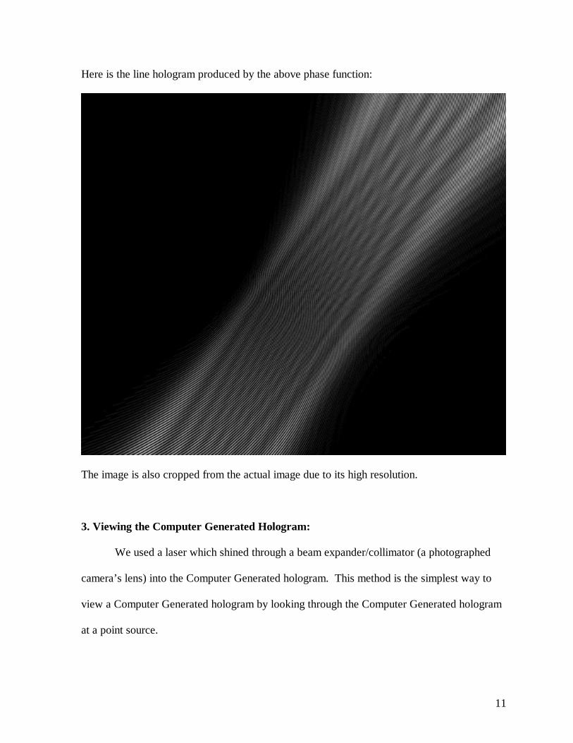
Here is the line hologram produced by the above phase function:
The image is also cropped from the actual image due to its high resolution.
3. Viewing the Computer Generated Hologram:
We used a laser which shined through a beam expander/collimator (a photographed
camera’s lens) into the Computer Generated hologram. This method is the simplest way to
view a Computer Generated hologram by looking through the Computer Generated hologram
at a point source.

12
Figure 3: Viewing Computer Generated Hologram
4. Holograms are stored in TIFF format
At the beginning of the thesis, I produced a Computer Generated Hologram by
emitting the hologram’s pixels into a PGM (Portable Graymap) file format. Since I wrote my
program on the Computer Science machine of Boston College, I was able to examine the
outcome of the hologram with XV. However, the process used to produce the results, that can
be viewed in three-dimensions, was to photograph the masks using a 35mm camera and slide
film. The slides are illuminated with a laser to produce the projected hologram. The
equipment, that can accomplish such task at Boston College’s Interactive Media Lab, requires
the file format to be in uncompressed TIFF file format. I discussed with Professor Ames, and
we decided to write our own TIFF library based on the TIFF 6.0 Specification. The TIFF

13
library, that we wrote, will store uncompressed images. Due to nature of our TIFF library, the
size of the Computer Generated Hologram is quite large. A line hologram with resolution of
4096x2730 occupies about 10 Megabytes of hard drive spaces.
5. Optimization
The running time of each Computer Generated Hologram is different depending on the
resolution of the image. In fact, the running time is proportional to the image width and
height. For example: the running time for a hologram of 4096x2730 will be proportional to
the product of 4096 times 2730. We observed the running time of both the point hologram
and line hologram programs, and we noticed that the line hologram program had the most
running time. We examined the codes and found out that since the phase function of the line
hologram iterates N times, where N is number of given points between two given end points.
Besides there are two square-root functions and a cosine function called in each iteration. To
improve speed, I edited the codes and changed the square-root function to a modified
iterative approximating square-root algorithm. These square-root functions are used to
compute the distances whose values change slightly in each iteration. Suppose distance D is
computed using the following formula:
222 zyxD ++=
The above function is needed to calculate the value of D at the very beginning of the phase
function. When the phase function loops through the number of given points, we can
approximate the square-root function as follow: we add the current value of D with the
quotient of (x2 + y2 + z2) and D. The sum then is divided by 2, the result will be the
approximated square-root value:

14
2
222
+++
=D
zyxDD Using this algorithm, we are able to reduce the running time of the
line hologram program to 30%. The following line hologram is produced with our new
square-root algorithm:

15
We also investigated in writing our own cosine function that uses the technique for iterative
approximation. We got the negative result because Profession Howard Straubing pointed out
that eventually the approximating cosine values would diverge throughout the loop. After
failing the first attempt to modify the cosine function, I tried to apply the Mclaurin series to
compute the cosine function. The formula is:
....!10!8!6!4!2
1)(108642
+−+−+−= xxxxxxCos
This method also failed to improve the speed of the program if I used more than 10
polynomial terms. When I used fewer polynomial terms the approximating cosine value is
not accurate enough.
IV. CONCLUSTION
Computer Generated Holograms are still at the beginning stage, and so much more can
be done. My thesis can be improved in future if I can create a Computer Generated Hologram
using an OpenGL library. The advantage of OpenGL is that it is possible to read the Z-buffer
of an image. Using the Z-buffer values, it is also possible to compute the dimensions and
depth cues of the image, thus more realistic holograms can be produced.
The applications of Computer Generated Holograms are many. Once the technology
for producing interactive holograms can be done in real time, we can watch television in
three-dimensional view. Teachers can enhance their lectures by showing an interactive
hologram of any object and model. For this reason I felt that Computer Generated Hologram
can be viewed as an effective teaching tool.
16
V. ACKNOWLEDGEMENT
My thesis has involved much time spent on researching the topic of Computer
Generated Hologram and implementing computer program. I greatly appreciate the time and
effort that my sponsored professor, William Ames, spent to make the final result possible. I
have learned a great deal from my thesis. I also would like to thank Professor Howard
Straubing for pointing out the problem of the approximating cosine function. Finally, I thank
Boston College Interactive Media Lab and the Audio Video department for their contribution
to the process of printing the Computer Generated Hologram on film and slide.
17
Bibliography:
1. TIFF 6.0 Specification Coverage by Sam Leffler / [email protected]
2. Optimization of Hologram Computation for Real-Time DisplayBy Mark Lucente, MIT Media Laboratory published in SPIE, Bellingham, WA, Feb. 1992
3. Optical Information Processing and HolographyBy W. Thomas Cathey, University of Colorado, Denver, Colorado
4. CRC Standard Mathematical Tables 25th EditionBy William H. Beyer, Ph.D