computer graphics & image processing
TRANSCRIPT

8/10/2019 Computer Graphics & Image Processing
http://slidepdf.com/reader/full/computer-graphics-image-processing 1/117
Biyani's Think Tank
Concept based notes
Computer Graphics M.Sc. IT
Bindiya PatelRevised By: Ms Ujjwala
BE (I.T.)
LecturerDeptt. of Information Technology
Biyani Girls College, Jaipur

8/10/2019 Computer Graphics & Image Processing
http://slidepdf.com/reader/full/computer-graphics-image-processing 2/117
2
Published by :
Think TanksBiyani Group of Colleges
Concept & Copyright :
Biyani Shikshan SamitiSector-3, Vidhyadhar Nagar,
Jaipur-302 023 (Rajasthan)
Ph : 0141-2338371, 2338591-95 Fax : 0141-2338007
E-mail : [email protected] :www.gurukpo.com; www.biyanicolleges.org
First Edition : 2009
Leaser Type Setted by :Biyani College Printing Department
While every effort is taken to avoid errors or omissions in this Publication, any mistake oromission that may have crept in is not intentional. It may be taken note of that neither the
publisher nor the author will be responsible for any damage or loss of any kind arising toanyone in any manner on account of such errors and omissions.

8/10/2019 Computer Graphics & Image Processing
http://slidepdf.com/reader/full/computer-graphics-image-processing 3/117
Computer Graphics 3
Preface
I am glad to present this book, especially designed to serve the needs of
the students. The book has been written keeping in mind the general weaknessin understanding the fundamental concepts of the topics. The book is self-explanatory and adopts the “Teach Yourself” style. It is based on question-answer pattern. The language of book is quite easy and understandable basedon scientific approach.
This book covers basic concepts related to the microbial understandings
about diversity, structure, economic aspects, bacterial and viral reproduction etc.Any further improvement in the contents of the book by making corrections,
omission and inclusion is keen to be achieved based on suggestions from thereaders for which the author shall be obliged.
I acknowledge special thanks to Mr. Rajeev Biyani, Chairman & Dr. SanjayBiyani, Director ( Acad.) Biyani Group of Colleges, who are the backbones andmain concept provider and also have been constant source of motivationthroughout this Endeavour. They played an active role in coordinating the variousstages of this Endeavour and spearheaded the publishing work.
I look forward to receiving valuable suggestions from professors of variouseducational institutions, other faculty members and students for improvement ofthe quality of the book. The reader may feel free to send in their comments andsuggestions to the under mentioned address.
Author
8/10/2019 Computer Graphics & Image Processing
http://slidepdf.com/reader/full/computer-graphics-image-processing 4/117
4
SyllabusM.Sc. IT
Computer Graphics
1. Graphic Application and Hardware : Need of Graphics, Display andInput Devices.
2. Transformation : Matrix Representation and Homogeneous Coordinates :Basic Transformations-2-dimensions and 3-dimensions : Translations,
Scaling and Rotations.3. Output Primitives : Line Drawing Algorithms : DDA Bresenham Line
Drawing, Circle Drawing Midpoint Algo, Ellipse Generating MidpointAlgo.
4. Clipping : Sutherland – Cohen Algo, Cyrus, Beck Algo.
5. Hidden Surface Removal : Back Face Detection, Depth Buffer, DepthSorting, Scan Line and A Buffer Techniques.
6. Curves and Surface : Hermit Curves, Bezier Curves, B – Spline Curves,Properties and Continuity Concepts.
7. Image Processing : Capture and Storage of Digital Images, File Formats,Basic Digital Techniques like Convolutions the Holding and HistogramManipulations, Image Enhancement, Geometric Manipulation and theirApplications the Automatic Identification and Extraction of Objects ofInterest.
8. Multimedia : Hardware, Software Application, Non Temporal Media :Text, Hypertext, Images, Cameras, Scanner, Frames Grabbers, Formats;Audio : Analog Video Operations, Compression, Digital Video MPEG, JPEG; Graphics Animation : Tweaking, Morphing Motion Specification,Simulating Acceleration.
□ □ □
8/10/2019 Computer Graphics & Image Processing
http://slidepdf.com/reader/full/computer-graphics-image-processing 5/117
Computer Graphics 5
Content
S.No. Name of Topic Page No.
1. Graphics Application and Hardware 7-191.1 Introduction to Computer Graphics1.2 Application of Computer Graphics1.3 Video Display Devices1.4 Raster Scan Displays
1.5 Random Scan Displays1.6 Color CRT Monitor1.7 Shadow Mask Methods
2. Transformation 20-302.1 Transformation in 2-dimension & 3-dimension2.2 Rotation in 2-dimansion & 3-dimension2.3 Scaling in 2-dimansion & 3-dimension2.4 Composite Transformation2.5 Reflection2.6 Shear
3. Output Primitives 31-493.1 Line Drawing Algorithms
(a) DDA(b) Bresenham‘s Algorithm
3.2 Circle Drawing Algorithm3.3 Ellipse Drawing Algorithm3.4 Boundary Fill Algorithm3.5 Flood Fill Algorithm
4. Clipping Algorithm 50-584.1 Introduction to Clipping
4.2 Application of Clipping4.3 Line Clipping Methods
(a) Cohen Sutherland Method(b) Cyrus – Beck Algorithm
8/10/2019 Computer Graphics & Image Processing
http://slidepdf.com/reader/full/computer-graphics-image-processing 6/117
6
S.No. Name of Topic Page No.
5. Visible Surface Detection 59-705.1 Depth Buffer Method5.2 Z – Buffer Method5.3 Object Space Method5.4 Image Space Method5.5 Painter‘s Algorithm 5.6 Back – Face Detection5.7 A – Buffer Method5.8 Scan Line Method
6. Curves and Surfaces 71-82
6.1 Bezier Curves and Surfaces6.2 Properties of Bezier Curves6.3 B - Spline Line and Surfaces6.4 Properties of B – Spline Curves6.5 Hermite Interpolation6.6 Continuity Conditions
7. Image Processing 83-907.1 Introduction to Image Processing7.2 Operations of Image Processing7.3 Application of Image Processing
7.4 Image Enhancement Techniques
8. Multimedia 91-1028.1 Introduction to Multimedia8.2 Application of Multimedia8.3 Tweaking8.4 Morphing8.5 Frame Grabbers8.6 Scanners8.7 Digital Cameras8.8 JPEG Compression Technique8.9 MPEG Compression Technique
8.10 Data Stream8.11 Hypertext / Hypermedia
□ □ □
8/10/2019 Computer Graphics & Image Processing
http://slidepdf.com/reader/full/computer-graphics-image-processing 7/117
Computer Graphics 7
Chapter-1
Graphics Application and Hardware
Q.1 What is Computer Graphics? What is its application?
Ans.: Computer has become a powerful tool for rapid and economical
production of pictures. There is virtually no area in which graphical
displays cannot is used to some advantage. To day computer graphics is
used delusively in such areas as science, medicine, Engineering etc.
Application of computer graphics :
(1) Computer – Aided Design : Generally used in the design of
building, automobiles, aircrafts, textiles and many other products.
(2) Presentation Graphics : This is used to produce illustration for or
to generate 35-cm slides or trans pare miss for use with projectors.
(3) Computer Art : Computer graphics methods are widely used in
both fine arts and Commercial Arts Applications.
(4) Entertainment : Computer graphics methods are now commonly
used in making motion pictures, music videos, television shows.
(5) Education and Training : Computer generated models of physical,
financial, and economic systems are after used as education aids.
(6) Visualization : This is used in connation with data sets related tocommerce, industry and other scientific areas.
(7) Image Processing : It applies techniques to modify or inter put
existing pictures such as photographs.
8/10/2019 Computer Graphics & Image Processing
http://slidepdf.com/reader/full/computer-graphics-image-processing 8/117
8
(8) Graphical user Interface : It is common now for software packagesto provide a graphical Interface.
Q.2 What are Video Display Devices?
or
Explain how Cathode Ray Tube works including details how colors are
achieved?
Ans.: The primary output device in a graphics system is a video controller. The
operation of most video monitors is based on the standard cathode-ray
tube (CRT) design.
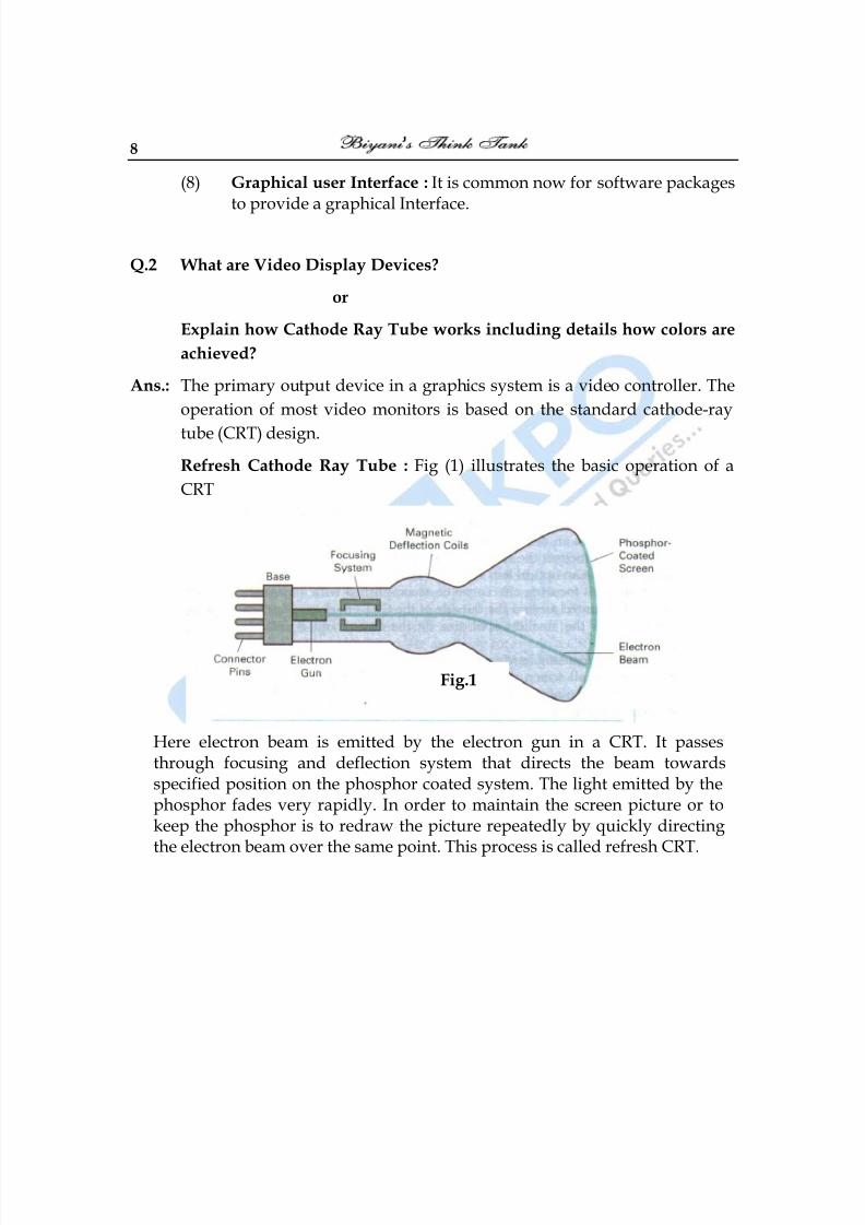
Refresh Cathode Ray Tube : Fig (1) illustrates the basic operation of a
CRT
Here electron beam is emitted by the electron gun in a CRT. It passesthrough focusing and deflection system that directs the beam towardsspecified position on the phosphor coated system. The light emitted by thephosphor fades very rapidly. In order to maintain the screen picture or tokeep the phosphor is to redraw the picture repeatedly by quickly directingthe electron beam over the same point. This process is called refresh CRT.
Fig.1
8/10/2019 Computer Graphics & Image Processing
http://slidepdf.com/reader/full/computer-graphics-image-processing 9/117
Computer Graphics 9
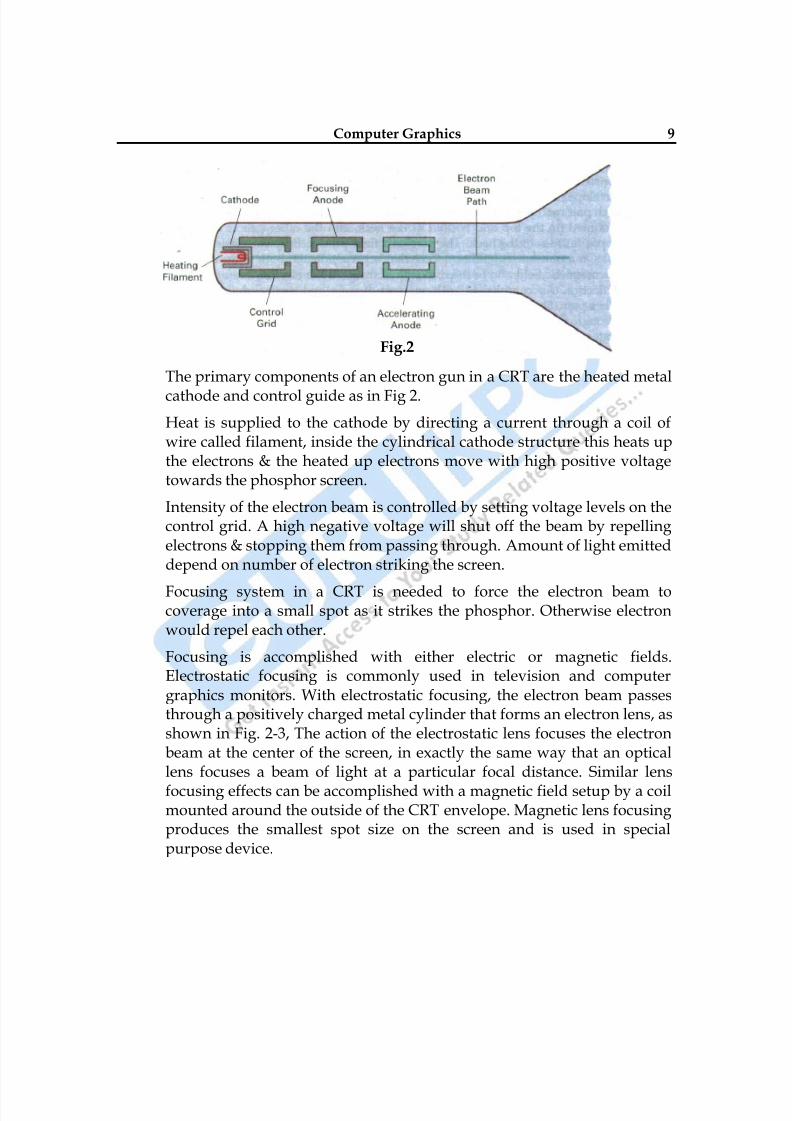
The primary components of an electron gun in a CRT are the heated metal
cathode and control guide as in Fig 2.
Heat is supplied to the cathode by directing a current through a coil ofwire called filament, inside the cylindrical cathode structure this heats upthe electrons & the heated up electrons move with high positive voltagetowards the phosphor screen.
Intensity of the electron beam is controlled by setting voltage levels on thecontrol grid. A high negative voltage will shut off the beam by repellingelectrons & stopping them from passing through. Amount of light emitteddepend on number of electron striking the screen.
Focusing system in a CRT is needed to force the electron beam tocoverage into a small spot as it strikes the phosphor. Otherwise electronwould repel each other.
Focusing is accomplished with either electric or magnetic fields.Electrostatic focusing is commonly used in television and computergraphics monitors. With electrostatic focusing, the electron beam passesthrough a positively charged metal cylinder that forms an electron lens, asshown in Fig. 2-3, The action of the electrostatic lens focuses the electronbeam at the center of the screen, in exactly the same way that an opticallens focuses a beam of light at a particular focal distance. Similar lens
focusing effects can be accomplished with a magnetic field setup by a coilmounted around the outside of the CRT envelope. Magnetic lens focusingproduces the smallest spot size on the screen and is used in specialpurpose device.
Fig.2
8/10/2019 Computer Graphics & Image Processing
http://slidepdf.com/reader/full/computer-graphics-image-processing 10/117
10
Additional focusing hardware is used in high-precision system to keepthe beam in focus at all screen position. The distance that the electronbeam must travel to different points on the screen varies because theradius of curvature for most CRTs is greater than the distance from thefocusing system to the screen center. There fore, the electron beamproperly only at the center of the screen. As the beam moves to the outeredges of the screen, displayed images become blurred. To compensate forthis, the system can adjust the focusing according to the screen position ofthe beam.
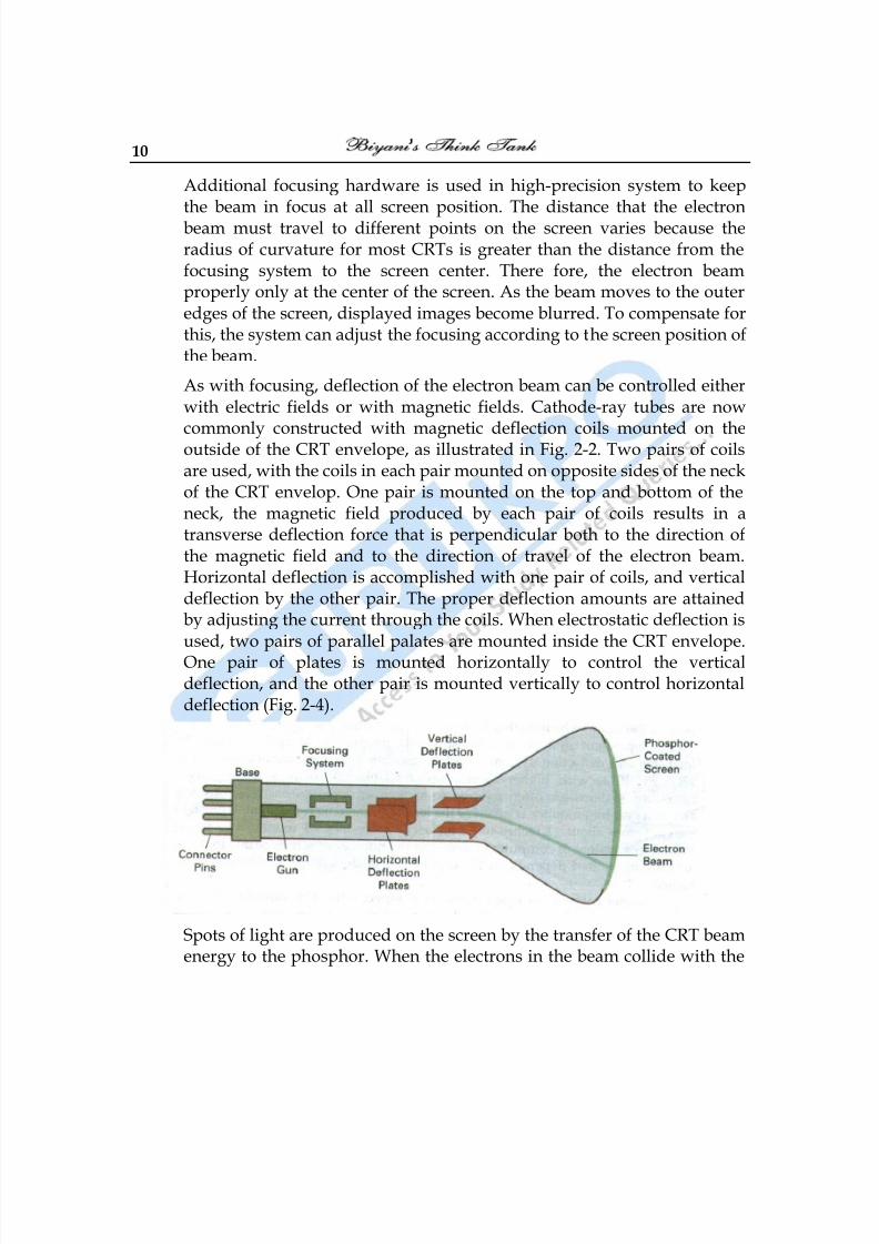
As with focusing, deflection of the electron beam can be controlled eitherwith electric fields or with magnetic fields. Cathode-ray tubes are now
commonly constructed with magnetic deflection coils mounted on theoutside of the CRT envelope, as illustrated in Fig. 2-2. Two pairs of coilsare used, with the coils in each pair mounted on opposite sides of the neckof the CRT envelop. One pair is mounted on the top and bottom of theneck, the magnetic field produced by each pair of coils results in atransverse deflection force that is perpendicular both to the direction ofthe magnetic field and to the direction of travel of the electron beam.Horizontal deflection is accomplished with one pair of coils, and verticaldeflection by the other pair. The proper deflection amounts are attainedby adjusting the current through the coils. When electrostatic deflection isused, two pairs of parallel palates are mounted inside the CRT envelope.One pair of plates is mounted horizontally to control the verticaldeflection, and the other pair is mounted vertically to control horizontaldeflection (Fig. 2-4).
Spots of light are produced on the screen by the transfer of the CRT beamenergy to the phosphor. When the electrons in the beam collide with the
8/10/2019 Computer Graphics & Image Processing
http://slidepdf.com/reader/full/computer-graphics-image-processing 11/117
Computer Graphics 11
phosphor coating, they are stopped and their energy is absorbed by thephosphor. Part of the beam energy is converted by friction into heatenergy, and the remainder causes electrons in the phosphor atoms tomove up to higher quantum-energy levels. After a short time, the―excited‖ phosphor electrons begin dropping back to their stable groundstate, giving up their extra energy as small quantum‘s of light energy.What we see on the screen is the combined effect of all the electron lightemissions: a glowing spot that quickly fades after all the excited phosphorelectrons have returned to their ground energy level. The frequency (orcolor) of the light emitted by the phosphor is proportional to the energydifference between the excited quantum state and the ground state.
Difference kinds of phosphor are available for use in a CRT. Besides color,a major difference between phosphor is their persistence : how long they
continue to emit light (that is, have excited electrons returning to the
ground states) after the CRT beam is removed. Persistence is defined as
the time it takes the emitted light from the screen to decay to one-tenth of
its original intensity. Lower-persistence phosphor requires higher refresh
rates to maintain a picture on the screen without flicker. A phosphor with
low persistence is useful for displaying highly complex, static, graphics
monitors are usually constructed with persistence in the range from 10 to
60 microseconds.
Figure 2-5 shows the intensity distribution of a spot on the screen. The
intensity is greatest at the center of the spot, and decreases with a
Gaussian distribution out to the edge of the spot. This distribution
corresponds to the cross-sectional electron density distribution of the CRT
beam.
The maximum number of points that can be displayed without overlap on
a CRT is referred to as the resolution. A more precise definition of
resolution is the number of points per centimeter that can be plotted
horizontally and vertically, although it is often simply stated as the totalnumber of points in each direction. Spot intensity has a Gaussian
distribution (Fig. 2-5), so two adjacent spot will appear distinct as long as
their separation is greater than the diameter at which each spot has
intensity in Fig. 2-6. Spot size also depends on intensity. As more
8/10/2019 Computer Graphics & Image Processing
http://slidepdf.com/reader/full/computer-graphics-image-processing 12/117
8/10/2019 Computer Graphics & Image Processing
http://slidepdf.com/reader/full/computer-graphics-image-processing 13/117
Computer Graphics 13
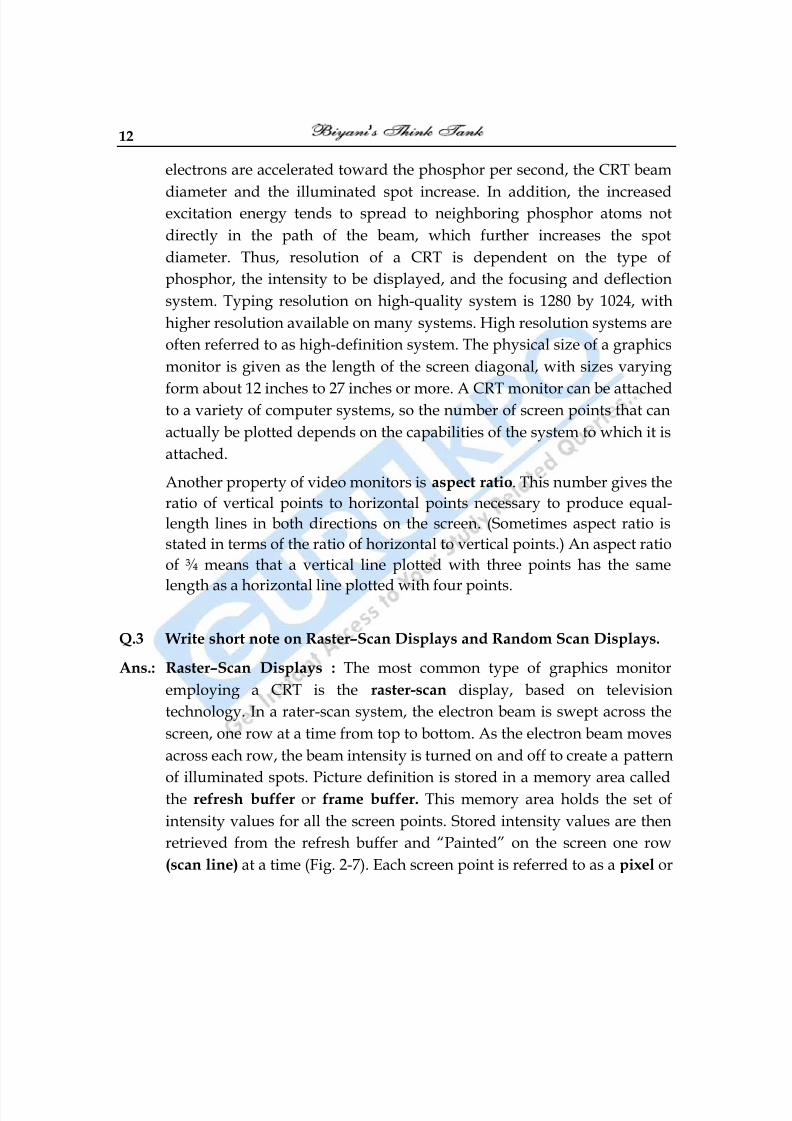
pel (shortened forms of picture element). The capability of a raster-scan
system to store intensity information for each screen point makes it wellsuited for the realistic display of scenes containing subtle shading and
color patterns. Home television sets and printers ate examples are
examples of other system using raster-scan methods.
Intensity range for pixel positions depends on the capability of the raster
system. In a simple black-and –white system, each screen point is either
on or off, so only one bit per pixel is needed to control the intensity of
screen position. For a bi-level system, a bit value of 1 indicates that the
electron beam is to be turned on at that position, and a value of 0 indicates
that the beam intensity is to be off. Additional bits are needed when colorand intensity variations can be displayed. Up to 24 bits per pixel are
included in high-quality system, which can require several megabytes of
storage for the frame buffer, depending on the resolution of the system. A
system with 24 bits per pixel and a screen resolution of 1024 by 1024
requires 3 megabytes of storage for the frame buffer. On a black-and-
white system with one bit per pixel, the frame buffer is commonly called a
bitmap. For system with multiple bits per pixel, the frame buffer is often
referred to as a pixmap.
Refreshing on raster-scan displays is carried out at the rate of 60 to 80
frames per second, although some systems are designed for higher refresh
rates. Sometimes, refresh rates are described in units of cycle per second,
or Hertz (Hz), where a cycle corresponds to one frame. Using these units,
we would describe a refresh rate of 60 frames per second as simply 60 Hz.
At the end of each scan line, the electron beam returns to the left side of
the screen to begin displaying the next scan line. The return to the left of
the screen, after refreshing each scan line, is called the horizontal retrace
of the electron beam. And at the end of each frame (displayed in 1/80 th to
1/60th of a second), the electron beam returns (vertical retrace) to the top
left corner of the screen to begin the next frame.
8/10/2019 Computer Graphics & Image Processing
http://slidepdf.com/reader/full/computer-graphics-image-processing 14/117
14
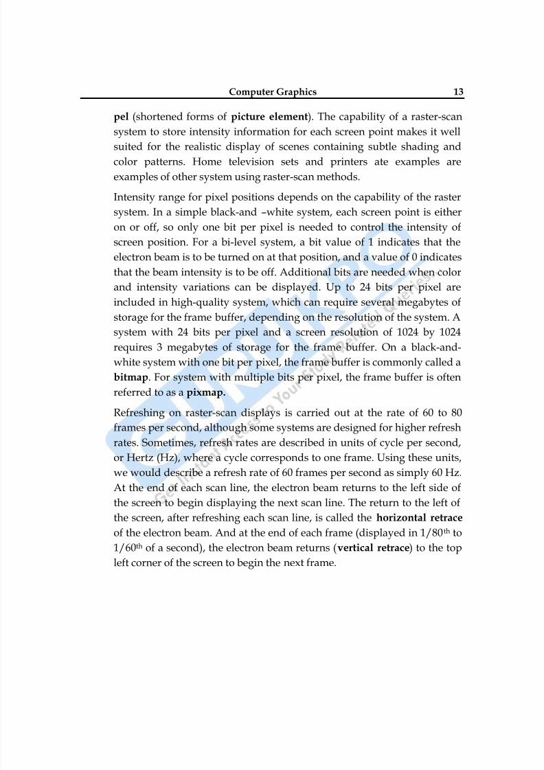
On some raster-scan system (and in TV sets), each frame is displayed in
two passes using an interlaced refresh procedure. In the first pass, the
beam sweeps across every other scan line form top to bottom. Then afterthe vertical retrace, the beam sweeps out the remaining scan lines (Fig. 2-
8). Interlacing of the scan lines in this way allows us to see the entire
screen displayed in one-half the time it would have taken to sweep across
all the lines at once from top to bottom. Interlacing is primarily used with
slower refreshing rates. On an older, 30 frame-per-seconds, no interlaced
display, for instance, some flicker is noticeable. But with interlacing, each
of the two passes can be accomplished in 1/60 th of a second, which brings
the refresh rate nearer to 60 frames per second. This is an effective
technique for avoiding flicker, providing that adjacent scan lines containsimilar display information.
Random Scan Displays : When operated as a random-scan display unit, a
CRT has the electron beam directed only to the parts of the screen where a
8/10/2019 Computer Graphics & Image Processing
http://slidepdf.com/reader/full/computer-graphics-image-processing 15/117
Computer Graphics 15
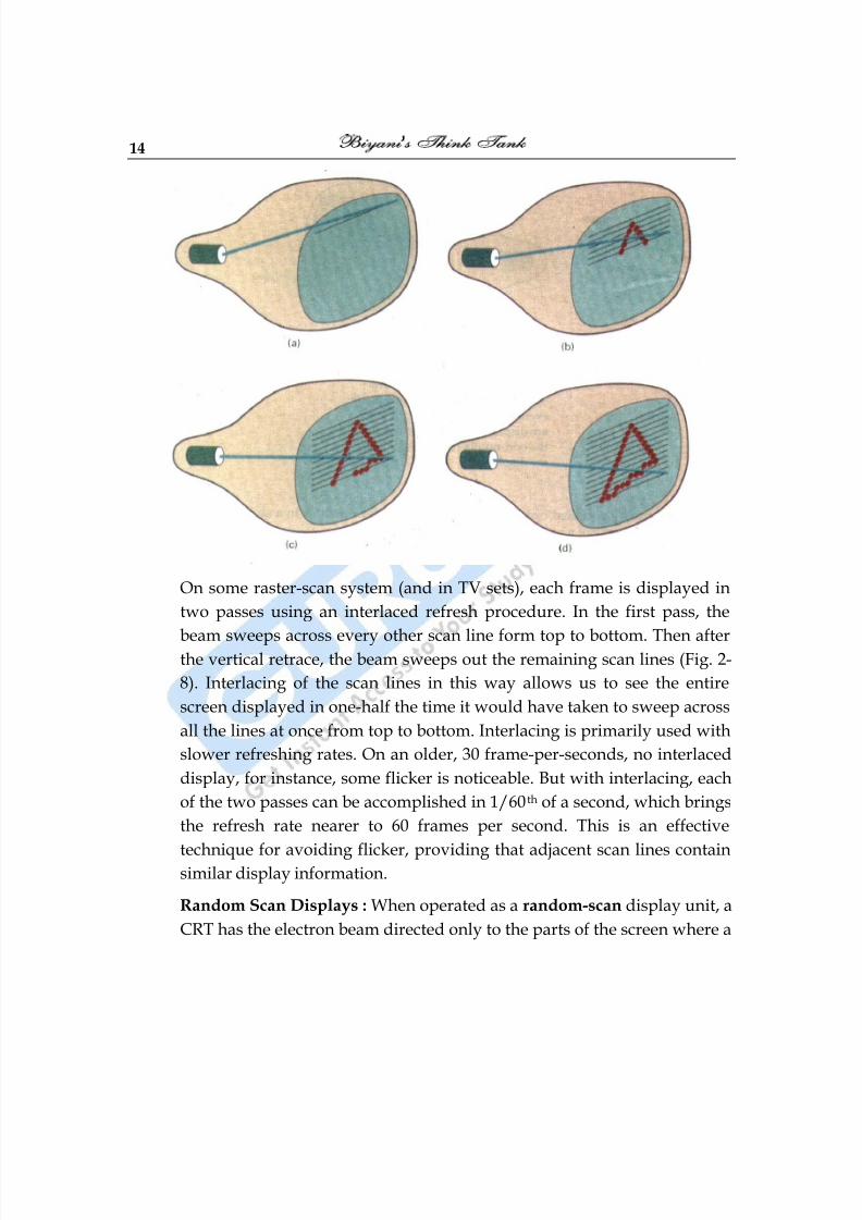
picture is to be drawn. Random-scan monitor draw a picture one line at a
time and for this reason are also referred to as vector displays (or stroke-writing of calligraphic displays). The component lines of a picture can be
drawn and refreshed by a random-scan system in any specified order
(Fig. 2-9). A pen plotter in a similar way and is an example of a random-
scan, hard-copy device.
Refresh rate on a random-scan system depends on the number of lines to
be displayed. Picture definition is now stored as a set of line-drawing
commands in an area of memory referred to as the refresh display file.
Sometimes the refresh display file is called the display list, display
program, or simply the refresh buffer. To display a specified picture, thesystem cycles through the set of commands in the display file, drawing
each component line in turn. After all line drawing commands have been
processed, the system cycle back to the first line command in the list.
Random-scan displays are designed to draw all the component lines of a
picture 30 to 60 times each second. High-quality vector systems are
capable of handling approximately 100,000 ―short‖ lines at this refresh
rate. When a small set of lines is to be displayed, each refresh cycle is
delayed to avoid refresh rates greater than 60 frames per second.
Otherwise, faster refreshing of the set of lines could burn out thephosphor.
Random-scan systems are designed for line-drawing applications and
can-not display realistic shaded scenes. Since picture definition is stored
8/10/2019 Computer Graphics & Image Processing
http://slidepdf.com/reader/full/computer-graphics-image-processing 16/117
16
as a set of line-drawing instruction and not as a set of intensity values for
all screen points, vector displays generally have higher resolution thenraster system. Also, vector displays produce smooth line drawings
because the CRT beam directly follows the line path. A raster system, in
contrast, produces jagged lines that are plotted as discrete point sets.
Q.4 Write short note on Color CRT Monitor. Explain Shadow MaskMethod.
Ans.: A CRT monitor displays color picture by using a combination of
phosphor that emit different-colored light. By combining the emitted light
from the different phosphor, a range of colors can be generated. The two
basic techniques for producing color displays with a CRT are the beam-
penetration method and the shadow-mask method.
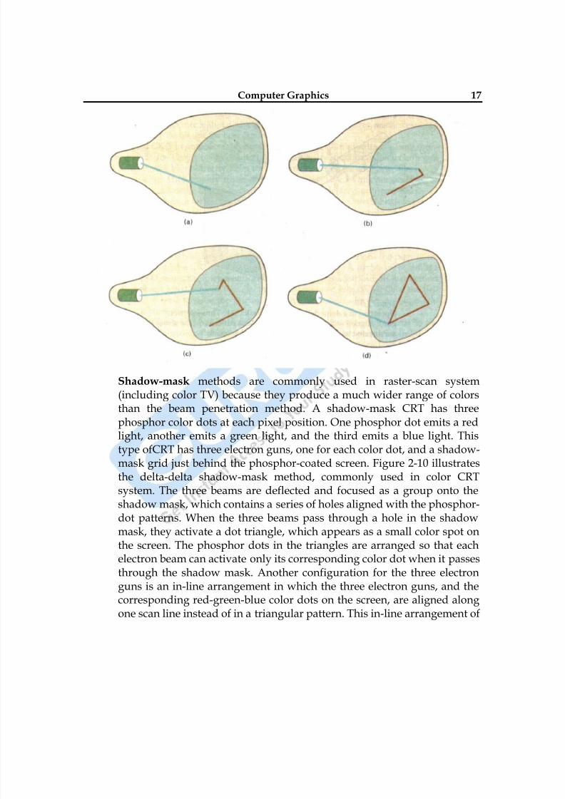
The beam-penetration method for displaying color pictures has been
used with random-scan monitors. Two layers of phosphor, usually red
and green, are coated onto the inside of the CRT screen, and the displayed
color depends on how far the electron beam penetrates into the phosphor
layers. A beam of slow electrons excites only the outer red layer. A beam
of very fast electron penetrates through the red layer and excites the innergreen layer. At intermediate beam speeds, combinations of red and green
light are emitted to show two additional colors, orange and yellow. The
speed of the electrons, and hence the screen color at any point, is
controlled by the beam-acceleration voltage. Beam penetration has been
an inexpensive way to produce color in random-scan monitor, but only
four colors are possible, and the quality of picture is not as good as with
other methods.
8/10/2019 Computer Graphics & Image Processing
http://slidepdf.com/reader/full/computer-graphics-image-processing 17/117
8/10/2019 Computer Graphics & Image Processing
http://slidepdf.com/reader/full/computer-graphics-image-processing 18/117
18
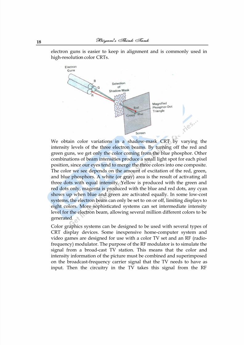
electron guns is easier to keep in alignment and is commonly used inhigh-resolution color CRTs.
We obtain color variations in a shadow-mask CRT by varying theintensity levels of the three electron beams. By turning off the red andgreen guns, we get only the color coming from the blue phosphor. Othercombinations of beam intensities produce a small light spot for each pixelposition, since our eyes tend to merge the three colors into one composite.The color we see depends on the amount of excitation of the red, green,and blue phosphors. A white (or gray) area is the result of activating all
three dots with equal intensity. Yellow is produced with the green andred dots only, magenta is produced with the blue and red dots, any cyanshows up when blue and green are activated equally. In some low-costsystems, the electron beam can only be set to on or off, limiting displays toeight colors. More sophisticated systems can set intermediate intensitylevel for the electron beam, allowing several million different colors to begenerated.
Color graphics systems can be designed to be used with several types ofCRT display devices. Some inexpensive home-computer system andvideo games are designed for use with a color TV set and an RF (radio-frequency) modulator. The purpose of the RF modulator is to simulate thesignal from a broad-cast TV station. This means that the color andintensity information of the picture must be combined and superimposedon the broadcast-frequency carrier signal that the TV needs to have asinput. Then the circuitry in the TV takes this signal from the RF
8/10/2019 Computer Graphics & Image Processing
http://slidepdf.com/reader/full/computer-graphics-image-processing 19/117
Computer Graphics 19
modulator, extracts the picture information, and paints it on the screen.As we might expect, this extra handling of the picture information by theRF modulator and TV circuitry decreased the quality of displayed images.
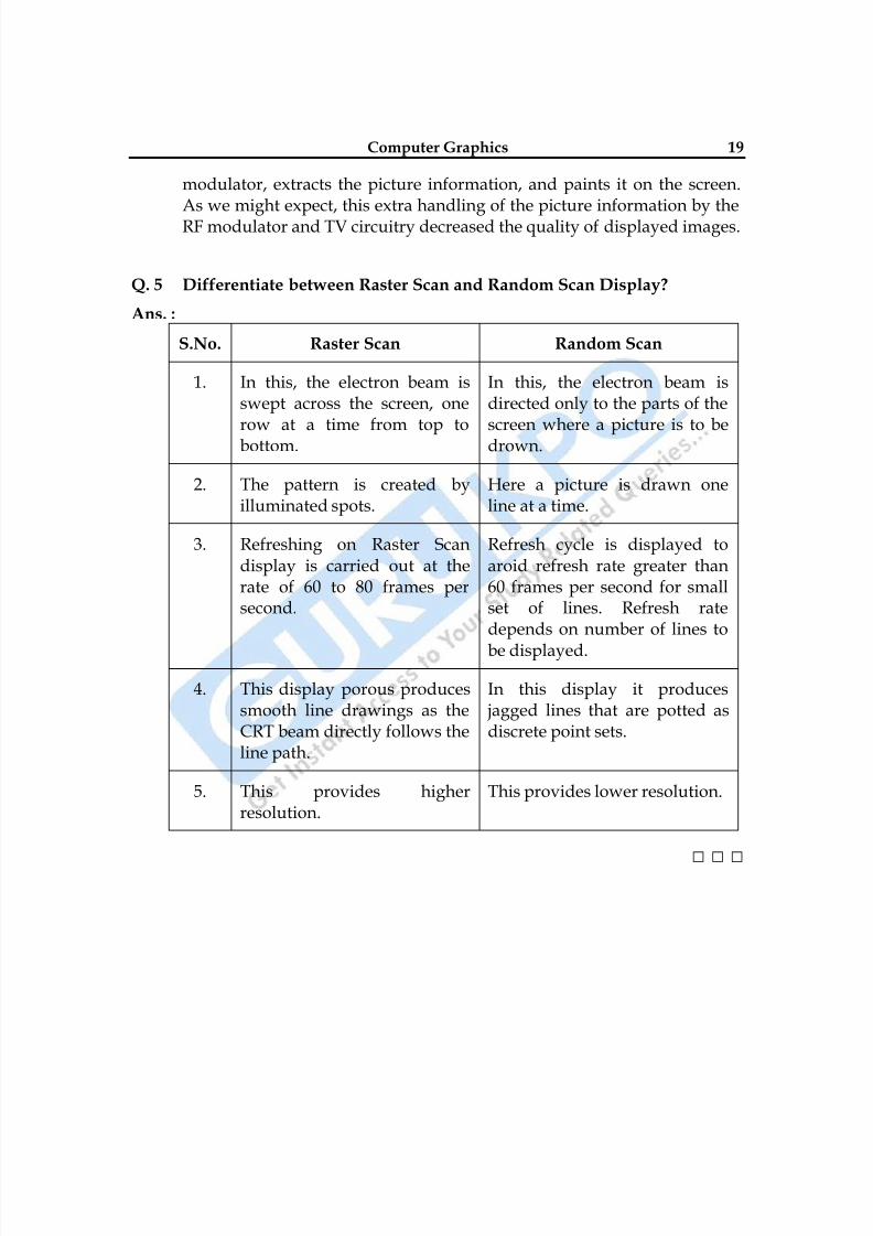
Q. 5 Differentiate between Raster Scan and Random Scan Display?
Ans. :
S.No. Raster Scan Random Scan
1. In this, the electron beam isswept across the screen, one
row at a time from top tobottom.
In this, the electron beam isdirected only to the parts of the
screen where a picture is to bedrown.
2. The pattern is created byilluminated spots.
Here a picture is drawn oneline at a time.
3. Refreshing on Raster Scandisplay is carried out at therate of 60 to 80 frames persecond.
Refresh cycle is displayed toaroid refresh rate greater than60 frames per second for smallset of lines. Refresh ratedepends on number of lines to
be displayed.
4. This display porous producessmooth line drawings as theCRT beam directly follows theline path.
In this display it produces jagged lines that are potted asdiscrete point sets.
5. This provides higherresolution.
This provides lower resolution.
□ □ □
8/10/2019 Computer Graphics & Image Processing
http://slidepdf.com/reader/full/computer-graphics-image-processing 20/117
20
Chapter-2
Transformation
Q.1 What is Transformation? What are general TransformationsTechniques?
Ans.: Transformation are basically applied to an object to reposition and resizetwo dimensional objects. There are three transformation techniques.
(1) Translation : A translation is applied to an object by repositioningit along a straight line path from one coordinate location toanother. We translate a two-dimensional point by addingtranslation distances tx and ty to the original coordinate position (x,y) to more the point to a new position (x‘, y‘).
x‘ = x + tx , y‘ = y + ty _ _ _ (1)
The translation distance pair (tx, ty) is called translation vector on
shift vector :
P 1
2
x
x , P‘ 1
2
x '=
x' , T x
y
t
t _ _ _ (2)
2 – dimensional translation matrix form :
P‘ = P + T _ _ _ (3)
In this case, we would write in matrix as row :
P = [x, y] , T = [tx , ty]
Translation is a rigid body transformation that moves objectwithout deformation.
8/10/2019 Computer Graphics & Image Processing
http://slidepdf.com/reader/full/computer-graphics-image-processing 21/117
Computer Graphics 21
That is T1 every point on the object is translated by the sameamount. A straight line segment is translated by applying thetransformation equation (3) to each of the line end point &redrawing the line between the new end point positions.
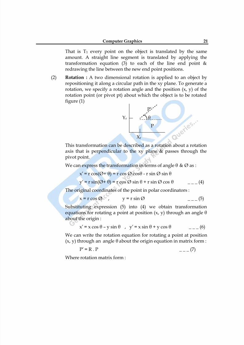
(2) Rotation : A two dimensional rotation is applied to an object byrepositioning it along a circular path in the xy plane. To generate arotation, we specify a rotation angle and the position (x, y) of therotation point (or pivot pt) about which the object is to be rotatedfigure (1)
P‘
Yr θ
P
Xr
This transformation can be described as a rotation about a rotationaxis that is perpendicular to the xy plane & passes through thepivot point.
We can express the transformation in terms of angle θ & Ø as :
x‘ = r cos(Ø+ θ) = r cos Ø cosθ - r sin Ø sin θ
y‘ = r sin(Ø+ θ) = r cos Ø sin θ + r sin Ø cos θ _ _ _ (4)
The original coordinates of the point in polar coordinators :
x = r cos Ø , y = r sin Ø _ _ _ (5)
Substituting expression (5) into (4) we obtain transformationequations for rotating a point at position (x, y) through an angle θabout the origin :
x‘ = x cos θ – y sin θ , y‘ = x sin θ + y cos θ _ _ _ (6)
We can write the rotation equation for rotating a point at position
(x, y) through an angle θ about the origin equation in matrix form :P‘ = R . P _ _ _ (7)
Where rotation matrix form :
8/10/2019 Computer Graphics & Image Processing
http://slidepdf.com/reader/full/computer-graphics-image-processing 22/117
22
P‘= R . Pθ θ
θ θ
cos -sin
sin cos
When coordinate positions are represented as row vectors instead
of column vectors, the matrix product in rotation eq.(7) is
transposed so that the transformed row coordinate vector [x‘, y‘] is
calculated as :
P‘T = (R . P)T = PT . RT _ _ _ (8)
(xr, yr) → Pivot Point
Where PT= [x, y] transposing RT of matrix R obtained by
interchanging rows & columns.
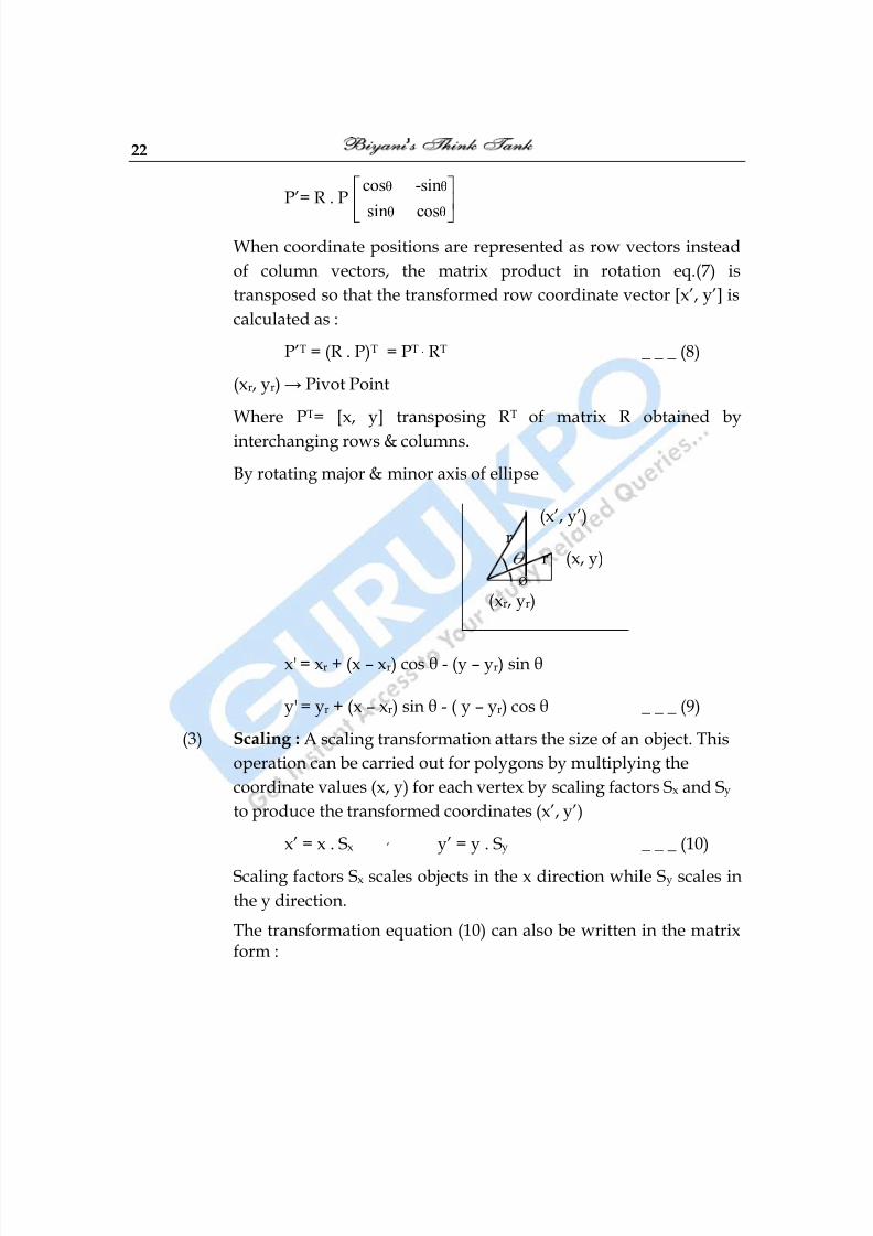
By rotating major & minor axis of ellipse
(x‘, y‘) r
r (x, y)ø
(xr, yr)
x' = xr + (x – xr) cos θ - (y – yr) sin θ
y' = yr + (x – xr) sin θ - ( y – yr) cos θ _ _ _ (9)
(3) Scaling : A scaling transformation attars the size of an object. This
operation can be carried out for polygons by multiplying the
coordinate values (x, y) for each vertex by scaling factors Sx and Sy
to produce the transformed coordinates (x‘, y‘)
x‘ = x . Sx ‗ y‘ = y . Sy _ _ _ (10)
Scaling factors Sx scales objects in the x direction while Sy scales in
the y direction.
The transformation equation (10) can also be written in the matrixform :
8/10/2019 Computer Graphics & Image Processing
http://slidepdf.com/reader/full/computer-graphics-image-processing 23/117
8/10/2019 Computer Graphics & Image Processing
http://slidepdf.com/reader/full/computer-graphics-image-processing 24/117
24
(2) Rotations : Two successive rotations applied to point P producethe transformed position :
P‘ = R(θ2). {P(θ1). P} = {R(θ2). R(θ1)}. P _ _ _ (6)
By multiplying 2–rotation matrices, we can verify that twosuccessive rotations are additive :
R(θ2). R(θ1) = R(θ1+ θ2) _ _ _ (7)
So that final rotated coordinates can be calculated with thecomposite rotation matrix as :
P‘ = R(θ1+ θ2) . P _ _ _ (8)
(3) Scaling : Concatenating transformation matrices for 2-successivescaling operations produce the following composite scaling matrix:
x2
y2
s 0 0
0 s 0
0 0 1
x1
y1
s 0 0
0 s 0
0 0 1
=x1 x2
y1 y2
s , s 0 0
0 s , s 0
0 0 1
_ _ _ (9)
Or S(Sx1, Sy2). S(Sx1, Sy1) = S(Sx1 . Sx2 , Sy1 . Sy2) _ _ _ (10)
The resulting matrix in this case indicates that successive scalingoperations are multiplicative. That is if we were to triple the size ofan object twice in successive the final size would be nine times thatof the original.
Q.3 Write short notes on following -
(1) Reflection
(2) Shear
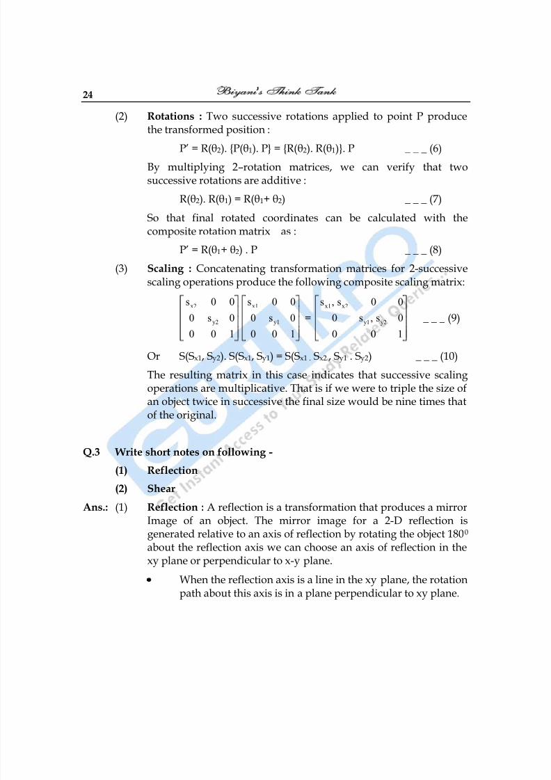
Ans.: (1) Reflection : A reflection is a transformation that produces a mirrorImage of an object. The mirror image for a 2-D reflection isgenerated relative to an axis of reflection by rotating the object 1800
about the reflection axis we can choose an axis of reflection in thexy plane or perpendicular to x-y plane.
When the reflection axis is a line in the xy plane, the rotationpath about this axis is in a plane perpendicular to xy plane.
8/10/2019 Computer Graphics & Image Processing
http://slidepdf.com/reader/full/computer-graphics-image-processing 25/117
Computer Graphics 25
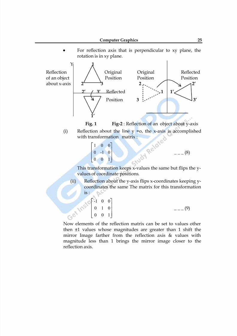
For reflection axis that is perpendicular to xy plane, therotation is in xy plane.
Y 1
Reflection Original Original Reflectedof an object Position Position Positionabout x-axis 2 3 2 2’
2’ 3’ Reflected 1 1’
Position 3 3’
1’ Fig. 1 Fig-2 : Reflection of an object about y-axis
(i) Reflection about the line y =o, the x-axis is accomplishedwith transformation matrix :
1 0 0
0 -1 0
0 0 1
_ _ _ (8)
This transformation keeps x-values the same but flips the y-values of coordinate positions.
(ii) Reflection about the y-axis flips x-coordinates keeping y-coordinates the same The matrix for this transformationis :
-1 0 0
0 1 0
0 0 1
_ _ _ (9)
Now elements of the reflection matrix can be set to values otherthen ±1 values whose magnitudes are greater than 1 shift the
mirror Image farther from the reflection axis & values withmagnitude less than 1 brings the mirror image closer to thereflection axis.
8/10/2019 Computer Graphics & Image Processing
http://slidepdf.com/reader/full/computer-graphics-image-processing 26/117
26
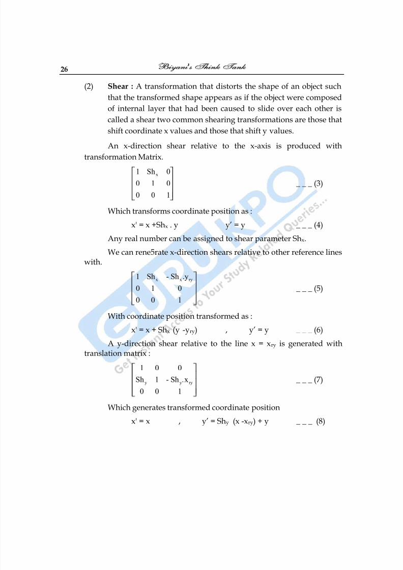
(2) Shear : A transformation that distorts the shape of an object such
that the transformed shape appears as if the object were composedof internal layer that had been caused to slide over each other is
called a shear two common shearing transformations are those that
shift coordinate x values and those that shift y values.
An x-direction shear relative to the x-axis is produced with
transformation Matrix.
x1 Sh 0
0 1 0
0 0 1
_ _ _ (3)
Which transforms coordinate position as :
x' = x +Shx . y y‘ = y _ _ _ (4)
Any real number can be assigned to shear parameter Shx.
We can rene5rate x-direction shears relative to other reference lineswith.
x x ry1 Sh - Sh .y
0 1 0
0 0 1
_ _ _ (5)
With coordinate position transformed as :
x' = x + Shx (y -yry) , y‘ = y _ _ _ (6)
A y-direction shear relative to the line x = xry is generated withtranslation matrix :
y y ry
1 0 0
Sh 1 - Sh .x
0 0 1
_ _ _ (7)
Which generates transformed coordinate position
x' = x , y‘ = Shy (x -xry) + y _ _ _ (8)
8/10/2019 Computer Graphics & Image Processing
http://slidepdf.com/reader/full/computer-graphics-image-processing 27/117
Computer Graphics 27
Q.4 Explain 3-different types of Transformations in 3- dimension?
Ans.: The there different types of transformations are :(1) Translation
(2) Rotation
(3) Scaling
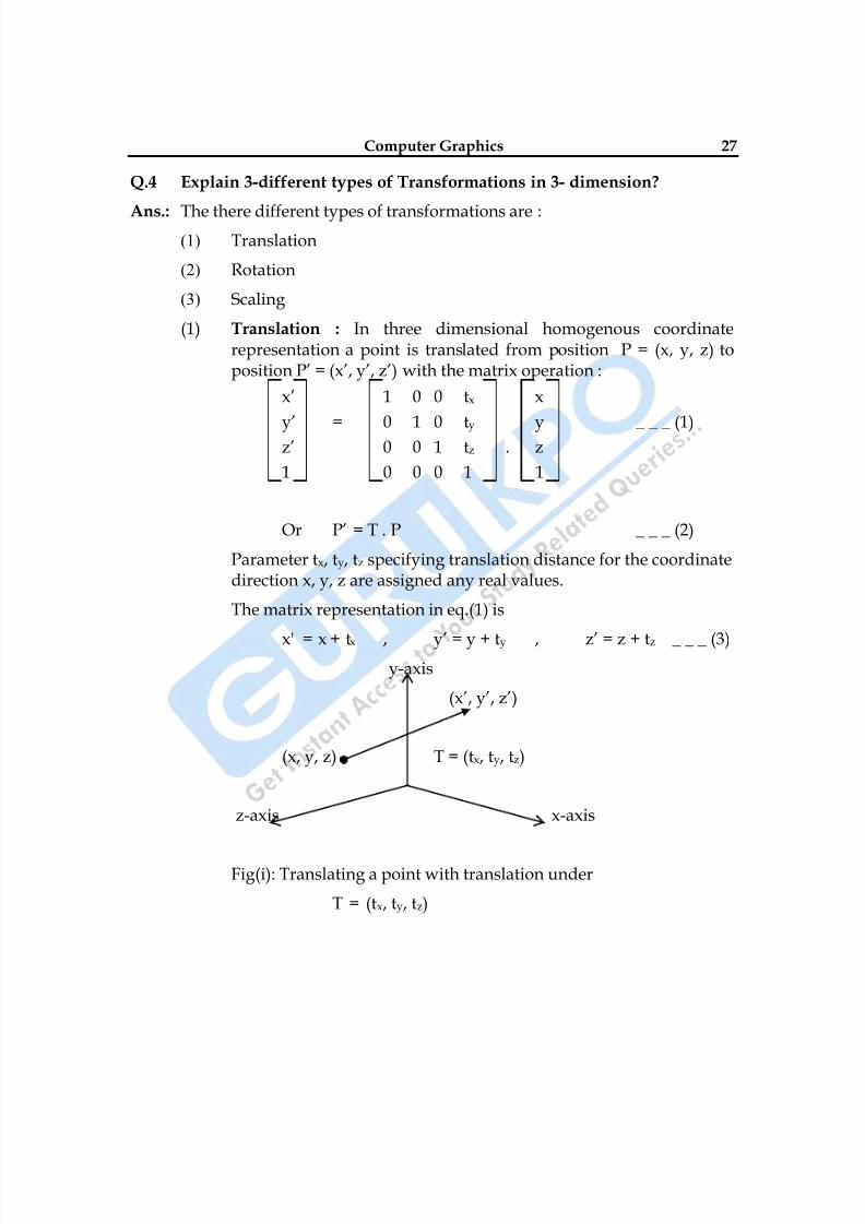
(1) Translation : In three dimensional homogenous coordinaterepresentation a point is translated from position P = (x, y, z) toposition P‘ = (x‘, y‘, z‘) with the matrix operation :
x‘ 1 0 0 tx x
y‘ = 0 1 0 ty y _ _ _ (1)z‘ 0 0 1 tz . z
1 0 0 0 1 1
Or P‘ = T . P _ _ _ (2)
Parameter tx, ty, tz specifying translation distance for the coordinatedirection x, y, z are assigned any real values.
The matrix representation in eq.(1) is
x' = x + tx , y‘ = y + ty , z‘ = z + tz _ _ _ (3)y-axis
(x‘, y‘, z‘)
(x, y, z) T = (tx, ty, tz)
z-axis x-axis
Fig(i): Translating a point with translation under
T = (tx, ty, tz)
8/10/2019 Computer Graphics & Image Processing
http://slidepdf.com/reader/full/computer-graphics-image-processing 28/117
28
An object is translated in 3-diminision by transforming each of the
defining points of the object. For an object represented as a set ofpolygon surfaces. We translate each vertex of each surface and
redraw the polygon facts in the new position.
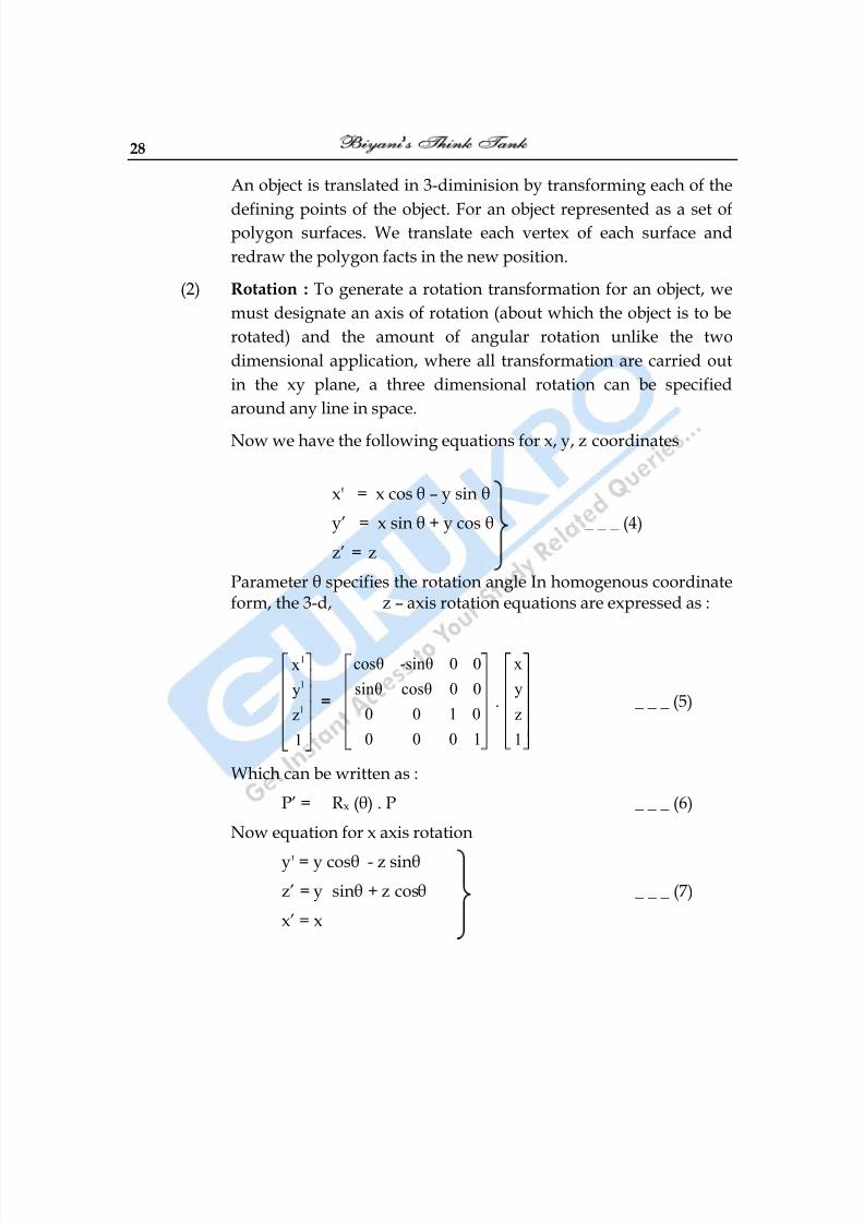
(2) Rotation : To generate a rotation transformation for an object, we
must designate an axis of rotation (about which the object is to be
rotated) and the amount of angular rotation unlike the two
dimensional application, where all transformation are carried out
in the xy plane, a three dimensional rotation can be specified
around any line in space.
Now we have the following equations for x, y, z coordinates
x' = x cos θ – y sin θ
y‘ = x sin θ + y cos θ _ _ _ (4)
z‘ = z
Parameter θ specifies the rotation angle In homogenous coordinateform, the 3-d, z – axis rotation equations are expressed as :
1
1
1
x
y
z
1
=
cosθ -sinθ 0 0
sinθ cosθ 0 0
0 0 1 0
0 0 0 1
.
x
y
z
1
_ _ _ (5)
Which can be written as :
P‘ = Rx (θ) . P _ _ _ (6)
Now equation for x axis rotation
y' = y cosθ - z sinθ
z‘ = y sinθ + z cosθ _ _ _ (7)
x‘ = x
8/10/2019 Computer Graphics & Image Processing
http://slidepdf.com/reader/full/computer-graphics-image-processing 29/117
Computer Graphics 29
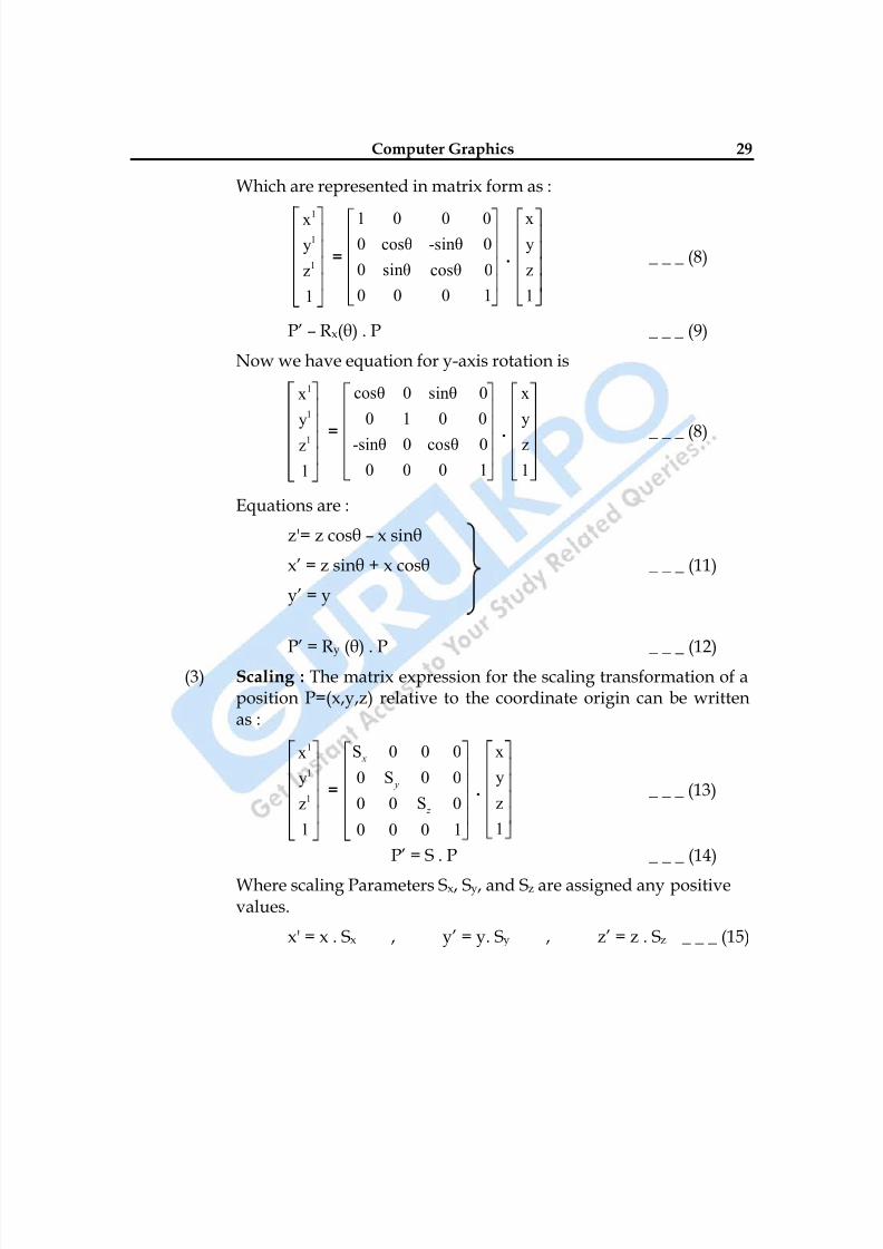
Which are represented in matrix form as :
1
1
1
x
y
z
1
=
1 0 0 00 cosθ -sinθ 0
0 sinθ cosθ 0
0 0 0 1
.
xy
z
1
_ _ _ (8)
P‘ – Rx(θ) . P _ _ _ (9)
Now we have equation for y-axis rotation is
1
1
1
x
y
z
1
=
cosθ 0 sinθ 0
0 1 0 0
-sinθ 0 cosθ 0
0 0 0 1
.
x
y
z
1
_ _ _ (8)
Equations are :
z'= z cosθ – x sinθ
x‘ = z sinθ + x cosθ _ _ _ (11)
y‘ = y
P‘ = Ry
(θ) . P _ _ _ (12)(3) Scaling : The matrix expression for the scaling transformation of a
position P=(x,y,z) relative to the coordinate origin can be writtenas :
1
1
1
x
y
z
1
=
S 0 0 0
00 S 0
S0 0 0
10 0 0
x
y
z
.
x
y
z
1
_ _ _ (13)
P‘ = S . P _ _ _ (14)
Where scaling Parameters Sx, Sy, and Sz are assigned any positivevalues.
x' = x . Sx , y‘ = y. Sy , z‘ = z . Sz _ _ _ (15)

8/10/2019 Computer Graphics & Image Processing
http://slidepdf.com/reader/full/computer-graphics-image-processing 30/117
30
Scaling an object with transformation changes the size of the objectand repositions the object relative to the coordinate origin. Also ifthe transformation is not all equal relative dimensions in the objectare changed. We pressure the original shape of an object withuniform scaling (Sx = Sy = Sz).
Scaling with respect to a selected fixed position (x f. yf. zf) can berepresented with following transformation sequence
(i) Translate the fixed point to the origin.
(ii) Scale the object relative to the coordinate origin.
(iii) Translate the fixed point to its original position.
□ □ □
8/10/2019 Computer Graphics & Image Processing
http://slidepdf.com/reader/full/computer-graphics-image-processing 31/117
Computer Graphics 31
Chapter-3
Output Primitives
Q.1 Explain the Line Drawing Algorithms? Explain DDA and Bresenham’sLine Algorithm.
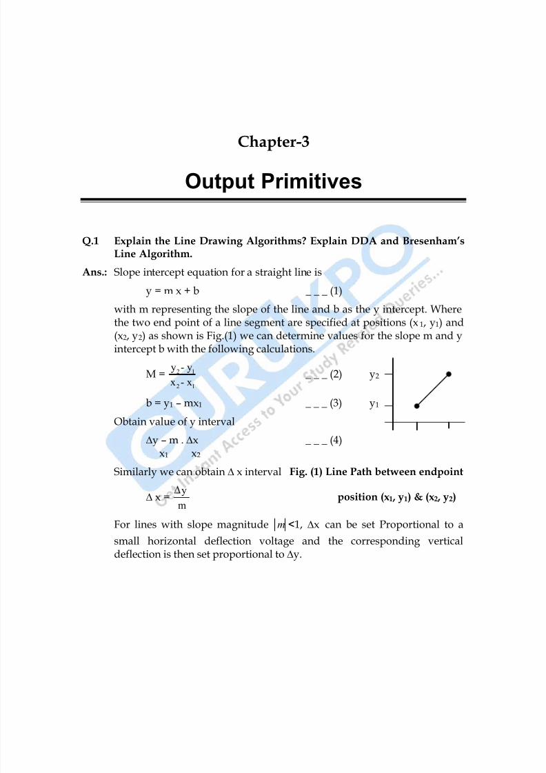
Ans.: Slope intercept equation for a straight line is
y = m x + b _ _ _ (1)
with m representing the slope of the line and b as the y intercept. Wherethe two end point of a line segment are specified at positions (x1, y1) and(x2, y2) as shown is Fig.(1) we can determine values for the slope m and yintercept b with the following calculations.
M = 2 1
2 1
y - y
x - x _ _ _ (2) y2
b = y1 – mx1 _ _ _ (3) y1 Obtain value of y interval
∆y – m . ∆x _ _ _ (4)x1 x2
Similarly we can obtain ∆ x interval Fig. (1) Line Path between endpoint
∆ x =y
m position (x1 , y1) & (x2 , y2)
For lines with slope magnitude m <1, ∆x can be set Proportional to a
small horizontal deflection voltage and the corresponding verticaldeflection is then set proportional to ∆y.
8/10/2019 Computer Graphics & Image Processing
http://slidepdf.com/reader/full/computer-graphics-image-processing 32/117
32
For lines with slope magnitude m >1, ∆y can be set proportional to a
small deflection voltage with the corresponding horizontal deflectionvoltage set proportional to ∆x.
For lines with m = 1 ∆x = ∆y.
DDA Algorithm : The Digital Differential Analyzer (DDA) is a scan.Conversion line Algorithm based on calculating either ∆y or ∆x usingequation (4) & (5). We sample the line at unit intervals in one coordinateand determine corresponding integer values nearest. The line paths forthe other coordinate.
Now consider first a line with positive slope, as shown in Fig.(1). If the
slope is less than one or equal to 1. We sample at unit x intervals (∆x = 1)compute each successive y values as :
yk+1 = yk + m _ _ _ (6)
Subscript k takes integer values starting form 1, for the first point &increase by 1 until the final end point is reached.
For lines with positive slope greater than 1, we reverse the role of x and y.That is we sample at unit y intervals (∆y = 1) and calculate eachsucceeding x value as :
xk+1 = xk +
1
m _ _ _ (7)
Equation (6) and (7) are based on assumption that lines are to beprocessed form left end point to the right end point.
If this processing is reversed the sign is changed
∆x = - 1 & ∆y = - 1
yk+1 = yk – m _ _ _ (8)
xk+1 = xk – 1
m _ _ _ (9)
Equations (6) to (9) are used to calculate pixel position along a line withnegative slope.
8/10/2019 Computer Graphics & Image Processing
http://slidepdf.com/reader/full/computer-graphics-image-processing 33/117
Computer Graphics 33
When the start endpoint is at the right we set ∆x = -1 and obtain y positionfrom equation (7) similarly when Absolute value of Negative slope isgreater than 1, we use ∆y = -1 & eq.(9) or we use ∆y = 1 & eq.(7).
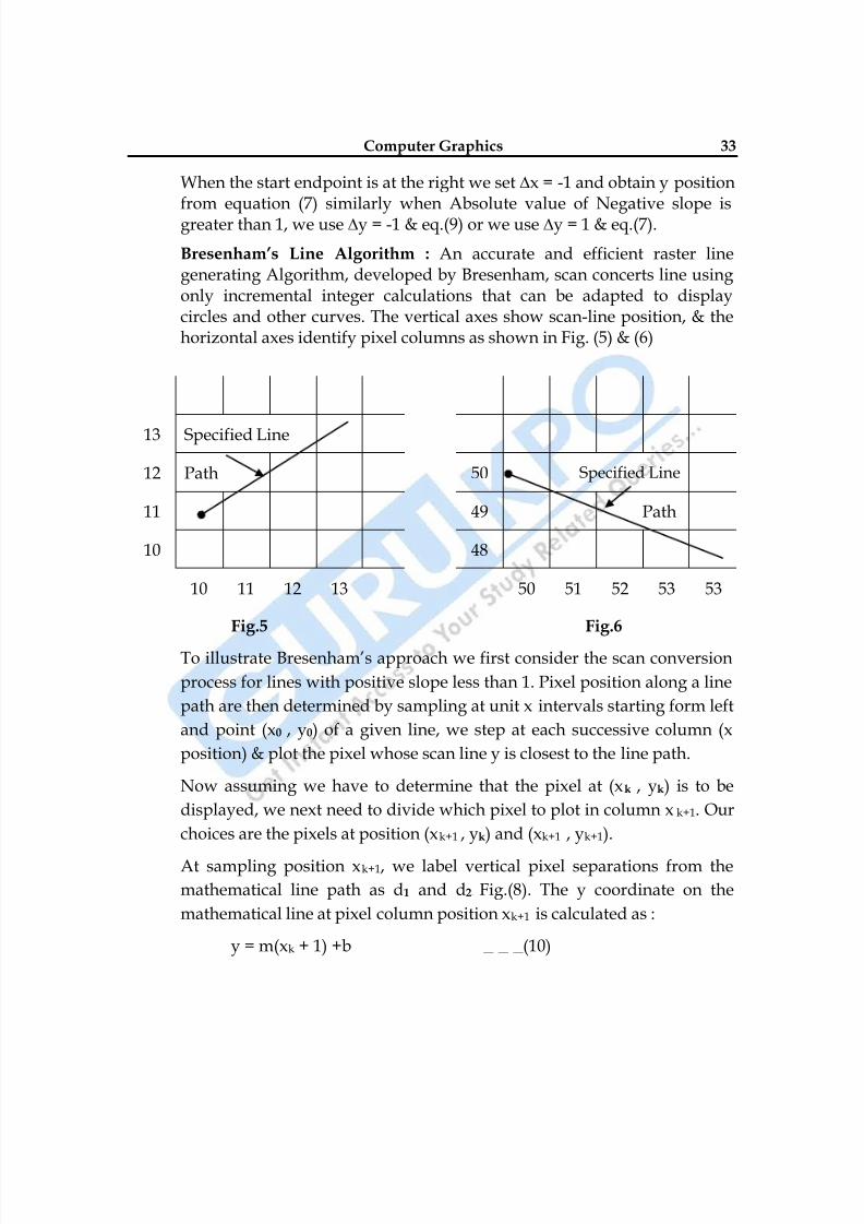
Bresenham’s Line Algorithm : An accurate and efficient raster linegenerating Algorithm, developed by Bresenham, scan concerts line usingonly incremental integer calculations that can be adapted to displaycircles and other curves. The vertical axes show scan-line position, & thehorizontal axes identify pixel columns as shown in Fig. (5) & (6)
13 Specified Line
12 Path 50 Specified Line
11 49 Path
10 48
10 11 12 13 50 51 52 53 53
Fig.5 Fig.6
To illustrate Bresenham‘s approach we first consider the scan conversion
process for lines with positive slope less than 1. Pixel position along a line
path are then determined by sampling at unit x intervals starting form left
and point (x0 , y0) of a given line, we step at each successive column (x
position) & plot the pixel whose scan line y is closest to the line path.
Now assuming we have to determine that the pixel at (xk , yk) is to be
displayed, we next need to divide which pixel to plot in column x k+1. Our
choices are the pixels at position (xk+1 , yk) and (xk+1 , yk+1).
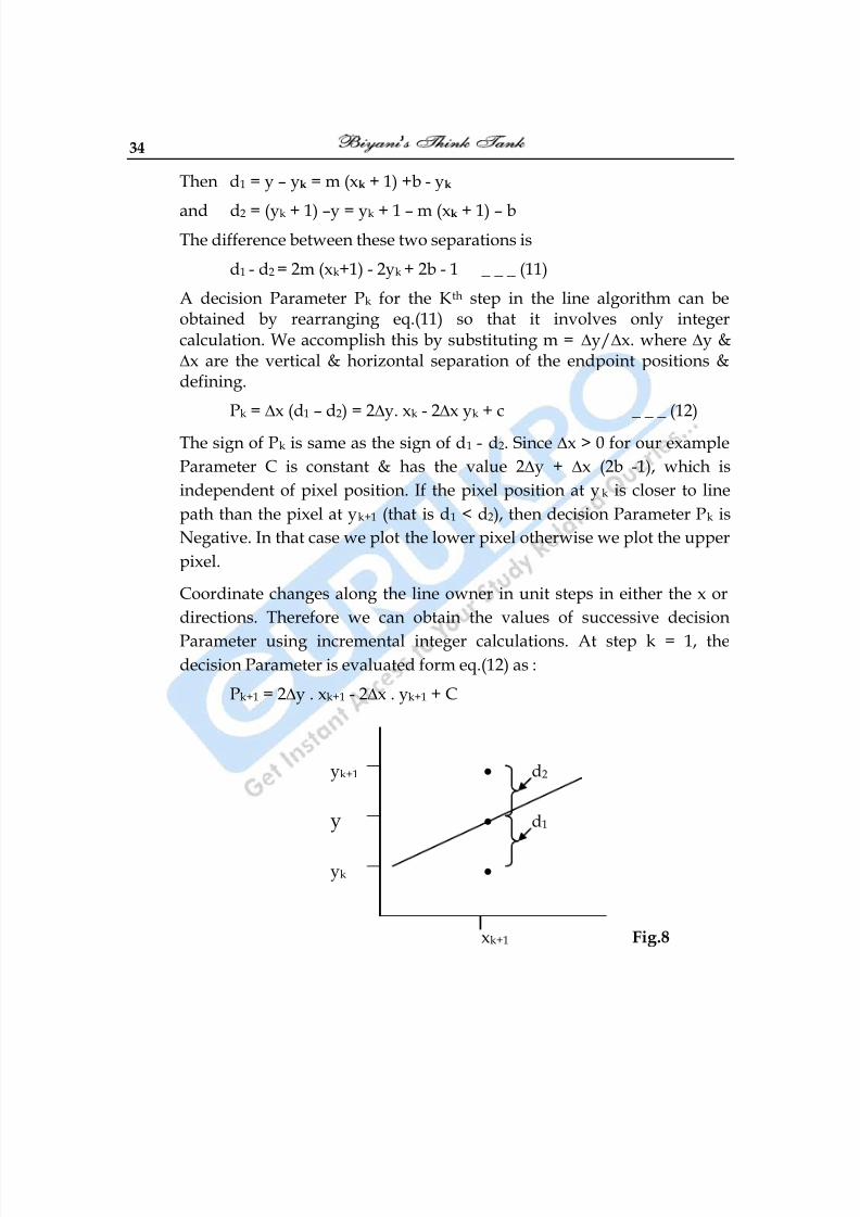
At sampling position xk+1, we label vertical pixel separations from the
mathematical line path as d1 and d2. Fig.(8). The y coordinate on the
mathematical line at pixel column position xk+1 is calculated as :
y = m(xk + 1) +b _ _ _ (10)
8/10/2019 Computer Graphics & Image Processing
http://slidepdf.com/reader/full/computer-graphics-image-processing 34/117
34
Then d1 = y – yk = m (xk + 1) +b - yk
and d2 = (yk + 1) –y = yk + 1 – m (xk + 1) – bThe difference between these two separations is
d1 - d2 = 2m (xk+1) - 2yk + 2b - 1 _ _ _ (11)
A decision Parameter Pk for the Kth step in the line algorithm can beobtained by rearranging eq.(11) so that it involves only integercalculation. We accomplish this by substituting m = ∆y/∆x. where ∆y &∆x are the vertical & horizontal separation of the endpoint positions &defining.
Pk = ∆x (d1 – d2) = 2∆y. xk - 2∆x yk + c _ _ _ (12)
The sign of Pk is same as the sign of d1 - d2. Since ∆x > 0 for our example
Parameter C is constant & has the value 2∆y + ∆x (2b -1), which is
independent of pixel position. If the pixel position at yk is closer to line
path than the pixel at yk+1 (that is d1 < d2), then decision Parameter Pk is
Negative. In that case we plot the lower pixel otherwise we plot the upper
pixel.
Coordinate changes along the line owner in unit steps in either the x or
directions. Therefore we can obtain the values of successive decision
Parameter using incremental integer calculations. At step k = 1, thedecision Parameter is evaluated form eq.(12) as :
Pk+1 = 2∆y . xk+1 - 2∆x . yk+1 + C
yk+1 • d2
y • d1
yk •
xk+1 Fig.8
8/10/2019 Computer Graphics & Image Processing
http://slidepdf.com/reader/full/computer-graphics-image-processing 35/117
Computer Graphics 35
Subtracting eq.(12) from the preceding equation we have
Pk+1 – Pk = 2∆y (xk+1 – xk) - 2∆x (yk+1 – yk)But xk+1 = xk + 1
So that, Pk+1 = Pk + 2∆y - 2∆x (yk+1 – yk) _ _ _ (13)
Where the term yk+1 - yk is either 0 or 1, depending on sign of ParameterPk.
This recursive calculation of decision Parameter is performed each integer
x position, starting at left coordinate endpoint of the line. The first
parameter P0 is evaluated from equation (12) at starting pixel position (x0,
y0) and with m evaluated as ∆y/∆x. P0 = 2∆y - ∆x _ _ _ (14)
Bresenham’s Line Drawing Algorithm for m <1 :
(1) Input the two line endpoints & store the left end point in (x0 , y0).
(2) Load (x0 , y0) into frame buffer that is plot the first point.
(3) Calculate constants ∆x, ∆y, 2∆y and 2∆y - 2∆x and obtain the
starting value for the decision parameter as : P0 = 2∆y - ∆x.
(4) At each xk along the line starting at k = 0, perform the following
test if Pk < 0 the next point to plot is (xk+1 , yk) and Pk+1 = Pk + 2∆yotherwise the next point to plot is (xk+1 , yk+1) and Pk+1 = Pk +2∆y -
2∆x.
(5) Repeat step 4 ∆x times.
Q.2 Digitize the line with end points (20, 10) & (30, 18) using Bresenham’sLine Drawing Algorithm.
Ans.: slope of line, m = 2 1
2 1
y - y
x - x =
18 - 10
30 - 20 =
8
10 = 0.8
∆x = 10 , ∆y = 8
Initial decision parameter has the value
P0 = 2∆y - ∆x = 2x8 – 10 = 6
Since P0 > 0, so next point is (xk + 1, yk + 1) (21, 11)
8/10/2019 Computer Graphics & Image Processing
http://slidepdf.com/reader/full/computer-graphics-image-processing 36/117
36
Now k = 0, Pk+1 = Pk + 2∆y - 2∆x
P1 = P0 + 2∆y - 2∆x = 6 + (-4)
= 2
Since P1 > 0, Next point is (22, 12)
Now k = 1, Pk+1 = Pk + 2∆y - 2∆x
P2 = 2 + (- 4)
= - 2
Since P2 < 0, Next point is (23, 12)
Now k = 2 Pk+1 = Pk + 2∆y
P2 = - 2 + 16
= 14
Since P3 > 0, Next point is (24, 13)
Now k = 3 Pk+1 = Pk + 2∆y - 2∆x
P4 = 14 – 4
= 10
Since P4 > 0, Next point is (25, 14)
Now k = 4 Pk+1 = Pk + 2∆y - 2∆x P5 = 10 – 4
= 6
Since P5 > 0, Next point is (26, 15)
Now k = 5 Pk+1 = Pk + 2∆y - 2∆x
P6 = 6 – 4
= 2
Since P6 > 0, Next point is (27, 16)
Now k = 6 Pk+1 = Pk + 2∆y - 2∆x
P7 = 2 + (- 4)
= - 2
Since P7 < 0, Next point is (28, 16)
8/10/2019 Computer Graphics & Image Processing
http://slidepdf.com/reader/full/computer-graphics-image-processing 37/117
Computer Graphics 37
Now k = 7 Pk+1 = Pk + 2∆y
P8 = - 2 + 16= 14
Since P8 > 0, Next point is (29, 17)
Now k = 8 Pk+1 = Pk + 2∆y - 2∆x
P9 = 14 – 4
= 10
Since P9 > 0, Next point is (30, 18)
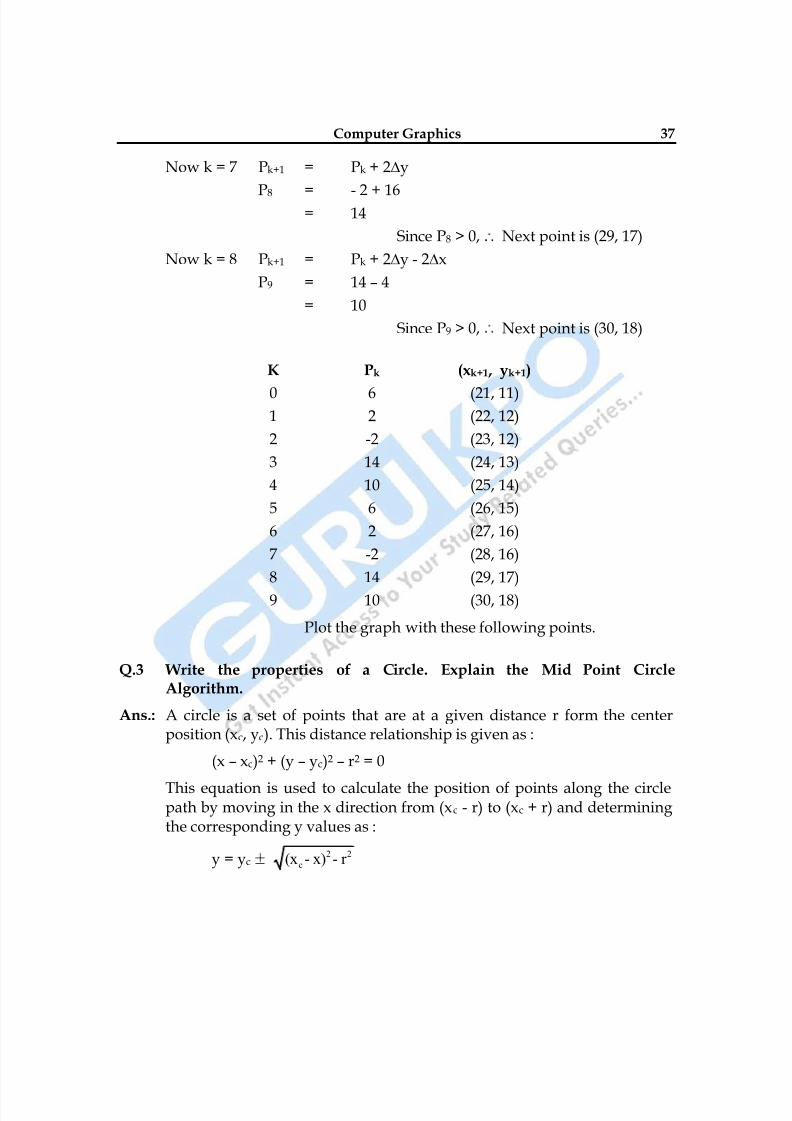
K Pk (xk+1 , yk+1)
0 6 (21, 11)1 2 (22, 12)
2 -2 (23, 12)
3 14 (24, 13)
4 10 (25, 14)
5 6 (26, 15)
6 2 (27, 16)
7 -2 (28, 16)
8 14 (29, 17)
9 10 (30, 18)
Plot the graph with these following points.
Q.3 Write the properties of a Circle. Explain the Mid Point CircleAlgorithm.
Ans.: A circle is a set of points that are at a given distance r form the centerposition (xc, yc). This distance relationship is given as :
(x – xc)2 + (y – yc)2 – r2 = 0
This equation is used to calculate the position of points along the circlepath by moving in the x direction from (xc - r) to (xc + r) and determiningthe corresponding y values as :
y = yc 2 2
c(x - x) - r
8/10/2019 Computer Graphics & Image Processing
http://slidepdf.com/reader/full/computer-graphics-image-processing 38/117
38
However this method is not the best method to calculate the circle pointas it requires heavy computation. Moreover spacing between the points isnot uniform. Another method that can be used by calculating the polarcoordinates r and θ where
x = xc + r cos θ
y = yc + r sin θ
Although this method results in equal spacing between the points but it
also requires heavy computation. The efficient method is incremental
calculation of decision parameter.
Mid Point Algorithm : We move in unit steps in the x-direction andcalculate the closed pixel position along the circle path at each step. For a
given radius r & screen center position (xc, yc). We first set our Algorithm
to calculate the position of points along the coordinate position (x0, y0).
These calculated positions are then placed at this proper screen position
by adding xc to x and yc to y.
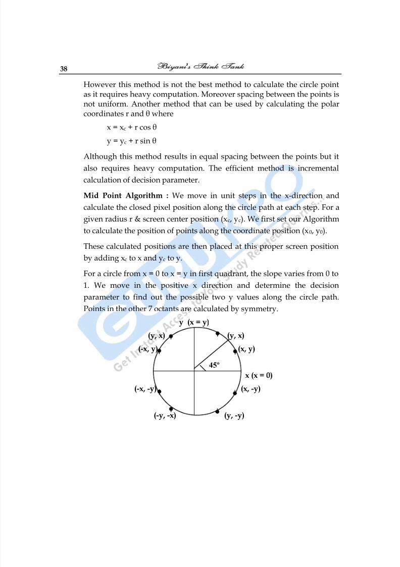
For a circle from x = 0 to x = y in first quadrant, the slope varies from 0 to
1. We move in the positive x direction and determine the decision
parameter to find out the possible two y values along the circle path.Points in the other 7 octants are calculated by symmetry.
y (x = y)
(y, x) (y, x)
(-x, y) (x, y)
x (x = 0)
(-x, -y) (x, -y)
(-y, -x) (y, -y)
45º
8/10/2019 Computer Graphics & Image Processing
http://slidepdf.com/reader/full/computer-graphics-image-processing 39/117
Computer Graphics 39
To apply this method we define a circle function as :
fcircle( x, y) = x2 + y2 - r2 _ _ _ (1)Any point (x, y) on the boundary of the circle with radius r satisfy theequation of fcircle( x, y) = 0
The relative position of any point (x, y) can be determined by checking thesign of circle function.
< 0 if (x, y) is inside circle boundary.
fcircle( x, y) = 0 if (x, y) on circle boundary. _ _ _ (2)
> 0 if (x, y) is outside circle boundary.
yk
yk -1
xk xk+1 xk+2
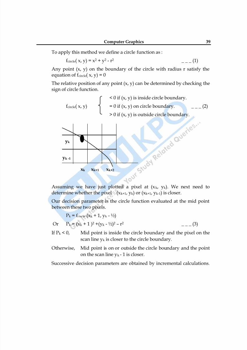
Assuming we have just plotted a pixel at (xk, yk). We next need todetermine whether the pixel (xk+1, yk) or (xk+1, yk-1) is closer.
Our decision parameter is the circle function evaluated at the mid pointbetween these two pixels.
Pk = fcircle (xk + 1, yk - ½)
Or Pk = (xk + 1 )2 +(yk - ½)2 – r2 _ _ _ (3)
If Pk < 0, Mid point is inside the circle boundary and the pixel on the
scan line yk is closer to the circle boundary.
Otherwise, Mid point is on or outside the circle boundary and the point
on the scan line yk - 1 is closer.
Successive decision parameters are obtained by incremental calculations.
8/10/2019 Computer Graphics & Image Processing
http://slidepdf.com/reader/full/computer-graphics-image-processing 40/117
40
Next decision parameter at next sampling position.
xk+1 + 1 = xk + 2Pk+1 = fcircle(xk+1 + 1, yk+1 - ½)
Or Pk+1 = [(xk + 1) + 1]2 + (yk+1 - ½)2 – r2
Or Pk+1 = Pk + 2(xk + 1) + (yk+12 – yk2) – (yk + 1 – yk) + 1 _ _ _ (4)
Successive increment for Pk is 2xk+1 +1(If Pk < 0) otherwise (2xk+1 +1 - 2yk+1)where
2xk+1 = 2xk + 2 & 2yk+1 = 2yk – 2
Initial decision parameter P0 is obtained as (0, r) = (x0, y0)
P0 = fcircle(x, y) = fcircle (1, r - ½) = 1 + (r - ½)2 – r2
Or P0 =5
4 - r
If r is a integer then P0 = 1 – r
Algorithm :
(1) Input radius r and circle center ( xc, yc) and obtain the first point on
circumference of a circle centered on origin (x0, y0) = (0, r)
(2) Calculate the initial value of the decision parameter as : P0 = 54
- r
(3) At each xk position, starting at k = 0 if Pk < 0 the next point along
the circle is (xk+1, yk) and Pk+1 = Pk + 2xk+1 + 1, otherwise the next
point along the circle is (xk + 1, yk - 1) and Pk+1 = Pk + 2xk+1 + 1 –
2yk+1 where 2xk+1 = 2xk + 2 & 2yk+1 = 2yk – 2.
(4) Determine symmetry points in other seven octants.
(5) Move each calculated pixel position (x, y) onto the circular path
centered on (xc, yc) & plot coordinate values x = x + xc & y = y + yc. (6) Repeat step (3) through (5) until x ≥ y.
8/10/2019 Computer Graphics & Image Processing
http://slidepdf.com/reader/full/computer-graphics-image-processing 41/117
Computer Graphics 41
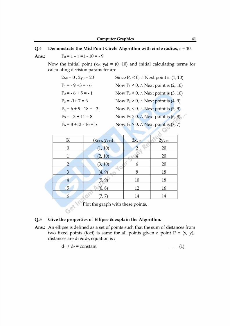
Q.4 Demonstrate the Mid Point Circle Algorithm with circle radius, r = 10.
Ans.: P0 = 1 – r =1 - 10 = - 9Now the initial point (x0, y0) = (0, 10) and initial calculating terms forcalculating decision parameter are
2x0 = 0 , 2y0 = 20 Since Pk < 0, Next point is (1, 10)
P1 = - 9 +3 = - 6 Now P1 < 0, Next point is (2, 10)
P2 = - 6 + 5 = - 1 Now P2 < 0, Next point is (3, 10)
P3 = -1+ 7 = 6 Now P3 > 0, Next point is (4, 9)
P4 = 6 + 9 - 18 = - 3 Now P4 < 0, Next point is (5, 9)
P5 = - 3 + 11 = 8 Now P5 > 0, Next point is (6, 8)
P6 = 8 +13 - 16 = 5 Now P6 > 0, Next point is (7, 7)
K (xk+1 , yk+1) 2xk+1 2yk+1
0 (1, 10) 2 20
1 (2, 10) 4 20
2 (3, 10) 6 20
3 (4, 9) 8 18
4 (5, 9) 10 18
5 (6, 8) 12 16
6 (7, 7) 14 14
Plot the graph with these points.
Q.5 Give the properties of Ellipse & explain the Algorithm.
Ans.: An ellipse is defined as a set of points such that the sum of distances fromtwo fixed points (foci) is same for all points given a point P = (x, y),distances are d1 & d2, equation is :
d1 + d2 = constant _ _ _ (1)
8/10/2019 Computer Graphics & Image Processing
http://slidepdf.com/reader/full/computer-graphics-image-processing 42/117
42
In terms of local coordinates
F1 = (x1, y1) & F2 (x2, y2)Equation is :
2 2 2 2
1 1 2 2(x - x ) +(y - y ) (x - x ) +(y - y ) 0 _ _ _ (2)
This can also be written in the form :
Ax2 + By2 + Cxy + Dx + Ey + F = 0 _ _ _ (3)
(More A, B, C, D, E, & F are evaluated in terms of focal coordinates &major minor axis).
Major axis – which extends form 1 point to other through foci.
Minor axis – which spans the shouter dimension bisecting major axisat ellipse center.
An interactive method for specifying an ellipse in an arbitrary orientationis to input two foci & a point on ellipse boundary & evaluate constant inequation (1) & so on.
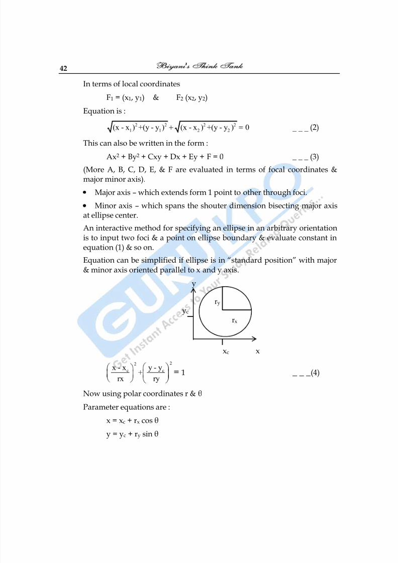
Equation can be simplified if ellipse is in ―standard position‖ with major& minor axis oriented parallel to x and y axis.
y
yc
xc x
22
c cx - x y - y+
rx ry= 1 _ _ _ (4)
Now using polar coordinates r & θParameter equations are :
x = xc + rx cos θ
y = yc + ry sin θ
r y
r x
8/10/2019 Computer Graphics & Image Processing
http://slidepdf.com/reader/full/computer-graphics-image-processing 43/117
Computer Graphics 43
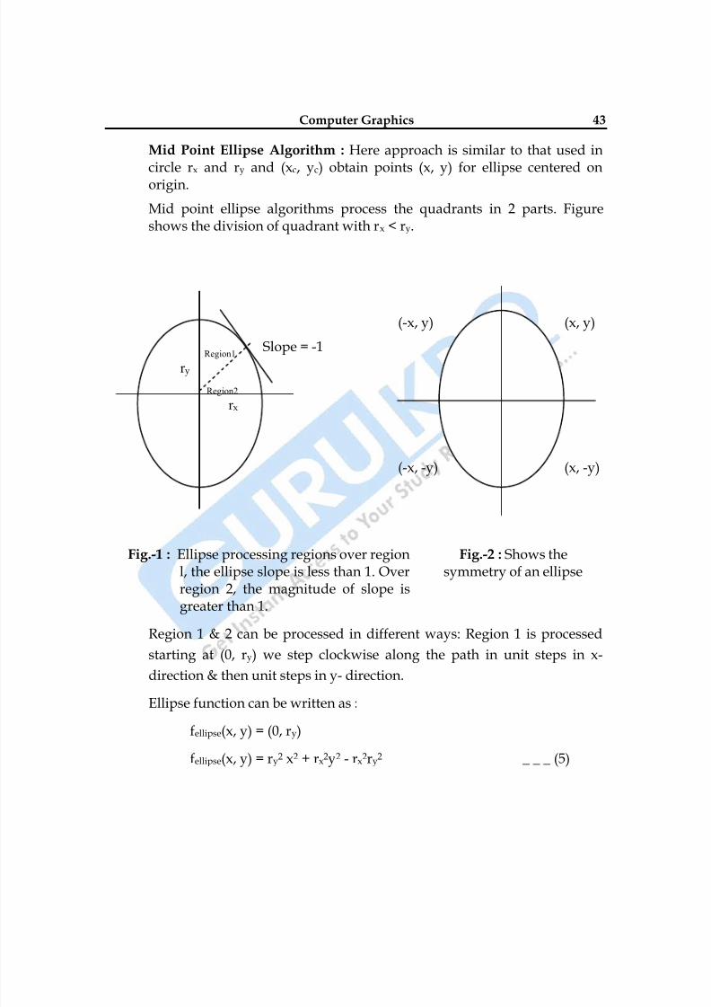
Mid Point Ellipse Algorithm : Here approach is similar to that used incircle rx and ry and (xc, yc) obtain points (x, y) for ellipse centered onorigin.
Mid point ellipse algorithms process the quadrants in 2 parts. Figureshows the division of quadrant with rx < ry.
(-x, y) (x, y)
Slope = -1
(-x, -y) (x, -y)
Fig.-1 : Ellipse processing regions over regionl, the ellipse slope is less than 1. Overregion 2, the magnitude of slope isgreater than 1.
Fig.-2 : Shows thesymmetry of an ellipse
Region 1 & 2 can be processed in different ways: Region 1 is processed
starting at (0, ry) we step clockwise along the path in unit steps in x-
direction & then unit steps in y- direction.
Ellipse function can be written as :
fellipse(x, y) = (0, ry)
fellipse(x, y) = ry2 x2 + rx2y2 - rx2ry2 _ _ _ (5)
Region1 r y
Region2 r x
8/10/2019 Computer Graphics & Image Processing
http://slidepdf.com/reader/full/computer-graphics-image-processing 44/117
8/10/2019 Computer Graphics & Image Processing
http://slidepdf.com/reader/full/computer-graphics-image-processing 45/117
Computer Graphics 45
With initial position (0, ry) the two terms evaluate to
2ry2x = 0 , 2rx2y = 2rx2ry Now when x & y are incremented the updated values are
2ry2 xk+1 = 2ry2 xk + 2ry2 , 2rx2 yk+1 = 2rx2 yk – 2rx2
And these values are compared at each step & we move out of Region 1when condition (7) is satisfied initial decision parameter for region 1 iscalculated as :
P10 = fellipse(x0, y0) = (1, ry – ½) = ry2 + rx2( ry - ½)2 – rx2 ry2
P10 = ry2 – rx2 ry + ¼ rx2 _ _ _ (10)
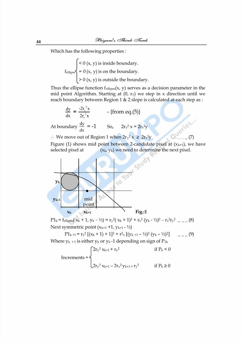
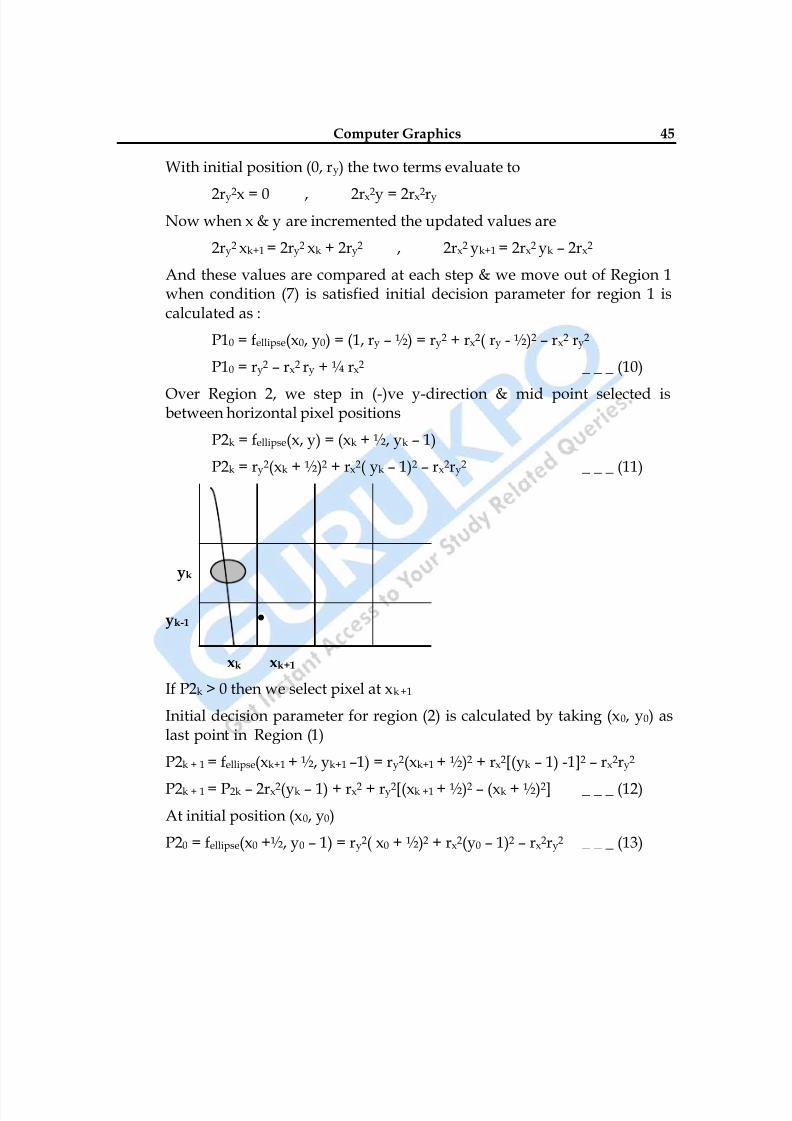
Over Region 2, we step in (-)ve y-direction & mid point selected isbetween horizontal pixel positions
P2k = fellipse(x, y) = (xk + ½, yk – 1)
P2k = ry2(xk + ½)2 + rx2( yk – 1)2 – rx2ry2 _ _ _ (11)
yk
yk-1 •
xk xk+1
If P2k > 0 then we select pixel at xk +1
Initial decision parameter for region (2) is calculated by taking (x0, y0) aslast point in Region (1)
P2k + 1 = fellipse(xk+1 + ½, yk+1 –1) = ry2(xk+1 + ½)2 + rx2[(yk – 1) -1]2 – rx2ry2
P2k + 1 = P2k – 2rx2(yk – 1) + rx2 + ry2[(xk +1 + ½)2 – (xk + ½)2] _ _ _ (12)
At initial position (x0, y0)
P20 = fellipse(x0 +½, y0 – 1) = ry2( x0 + ½)2 + rx2(y0 – 1)2 – rx2ry2 _ _ _ (13)
8/10/2019 Computer Graphics & Image Processing
http://slidepdf.com/reader/full/computer-graphics-image-processing 46/117
46
Mid Point Ellipse Algorithm :
(1)
Input rx, ry and ellipse centre (xc, yc) obtain the first point (x0, y0) =(0, ry)
(2) Calculate the initial value of the decision parameter in region 1 as
P10 = ry2 – rx2ry + ¼ rx2
(3) At each xk position in region 1, starting at K = 0. If Pk < 0, then nextpoint along ellipse is (xk+1, yk) and P1k+1 = P1k + 2ry
2xk+1 + ry2
otherwise next point along the circle is (xk +1, yk –1) and P1k+1 = P1k + 2ry2xk + 1 – 2rx2yk + 1 + ry2 with 2ry2xk+1 = 2ry2xk + 2ry2 , 2rx2yk+1 =2rx
2yk – 2rx2 and continue until 2ry
2x ≥ 2rx2y.
(4) Calculate the initial value of the decision parameter in region (2)using last point (x0, y0) calculated in region 1 as P20 = ry2 (x0 +½)2 + rx2 (y0 – 1)2 – rx2ry2.
(5) At each yk position in region (2), starting at k = 0 perform followingtest : If P2k > 0 next point is (xk, yk – 1) and P2k+1 = P2k – 2rx2yk + 1 +rx2 otherwise next point is ( xk + 1, yk – 1) and P2k+1 = P2k + 2ry2xk +
1 – 2rx2yk+1 + rx2.
(6) Determine the symmetry points in other three quadrants.
(7) More each calculated pixel position (x, y). Center on (xc, yc), plot
coordinate values x = x + xc & y = y + yc.
(8) Repeat the steps for region 1 until 2ry2x ≥ 2rx
2y.
Q.6 Illustrate the Mid Point Ellipse Algorithm by ellipse parameter rx = 8 ry = 6
Ans.: rx2 = 64, ry2 = 36
2rx2 = 128, 2ry2 = 72
P10 = 36 – (64 x 6) +1
4
x 64 = 36 – 384 + 16 = – 332
P10 < 0 Next point is (1, 6)
P11 = – 332 + 72 x 1 + 36 = – 332 + 108 = – 224
P11 < 0 Next point is (2, 6)
8/10/2019 Computer Graphics & Image Processing
http://slidepdf.com/reader/full/computer-graphics-image-processing 47/117
Computer Graphics 47
P12 = – 224 + 72 x 2 + 36 = – 224 + 144 + 36 = – 44
P12 < 0 Next point is (3, 6)P13 = – 44 + 72 x 3 + 36 = – 44 + 216 + 36 = 208
P13 > 0 Next point is (4, 5)
P14 = 208 + 72 x 4 – 128 x 5 +36 = 208 + 288 – 640 + 36 = – 108
P14 < 0 Next point is (5, 5)
P15 = – 108 + 72 x 5 + 36 = 288
P15 > 0 Next point is (6, 4)
P16 = 288 + 72 x 6 – 128 x 4 + 36 = 244
P16 > 0 Next point is (7, 3)P17 = 244 + 72 x 7 – 128 x 3 + 36 = 1168
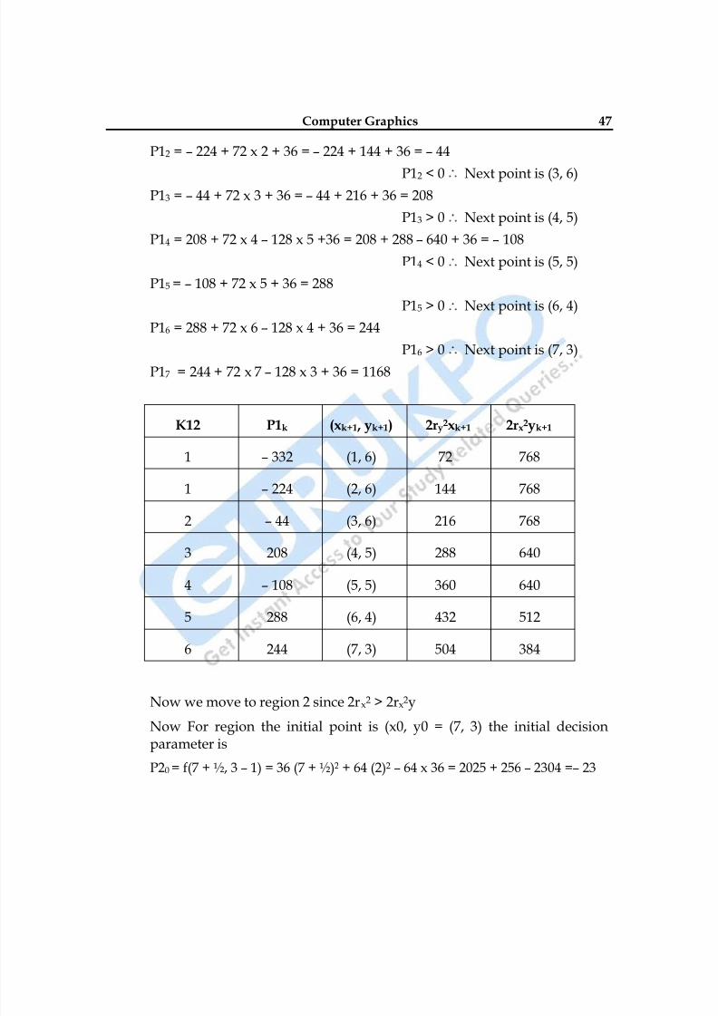
K12 P1k (xk+1 , yk+1) 2ry2xk+1 2rx2yk+1
1 – 332 (1, 6) 72 768
1 – 224 (2, 6) 144 768
2 – 44 (3, 6) 216 768
3 208 (4, 5) 288 640
4 – 108 (5, 5) 360 640
5 288 (6, 4) 432 512
6 244 (7, 3) 504 384
Now we move to region 2 since 2rx2 > 2rx2y
Now For region the initial point is (x0, y0 = (7, 3) the initial decisionparameter is
P20 = f(7 + ½, 3 – 1) = 36 (7 + ½)2 + 64 (2)2 – 64 x 36 = 2025 + 256 – 2304 =– 23
8/10/2019 Computer Graphics & Image Processing
http://slidepdf.com/reader/full/computer-graphics-image-processing 48/117
48
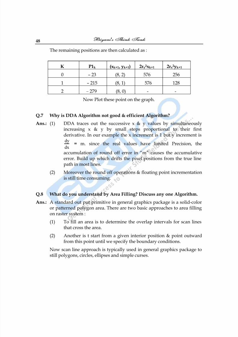
The remaining positions are then calculated as :
K P1k (xk+1 , yk+1) 2ry2xk+1 2rx2yk+1
0 – 23 (8, 2) 576 256
1 – 215 (8, 1) 576 128
2 – 279 (8, 0) - -
Now Plot these point on the graph.
Q.7 Why is DDA Algorithm not good & efficient Algorithm?Ans.: (1) DDA traces out the successive x & y values by simultaneously
increasing x & y by small steps proportional to their firstderivative. In our example the x increment is 1 but y increment isdy
dx = m. since the real values have limited Precision, the
accumulation of round off error in ―m‖ causes the accumulativeerror. Build up which drifts the pixel positions from the true linepath in most lines.
(2) Moreover the round off operations & floating point incrementation
is still time consuming.
Q.8 What do you understand by Area Filling? Discuss any one Algorithm.
Ans.: A standard out put primitive in general graphics package is a solid-coloror patterned polygon area. There are two basic approaches to area fillingon raster system :
(1) To fill an area is to determine the overlap intervals for scan linesthat cross the area.
(2)
Another is t start from a given interior position & point outwardfrom this point until we specify the boundary conditions.
Now scan line approach is typically used in general graphics package tostill polygons, circles, ellipses and simple curses.
8/10/2019 Computer Graphics & Image Processing
http://slidepdf.com/reader/full/computer-graphics-image-processing 49/117
Computer Graphics 49
Fill methods starting from an interior point are useful with more complexboundaries and in interactive painting systems.
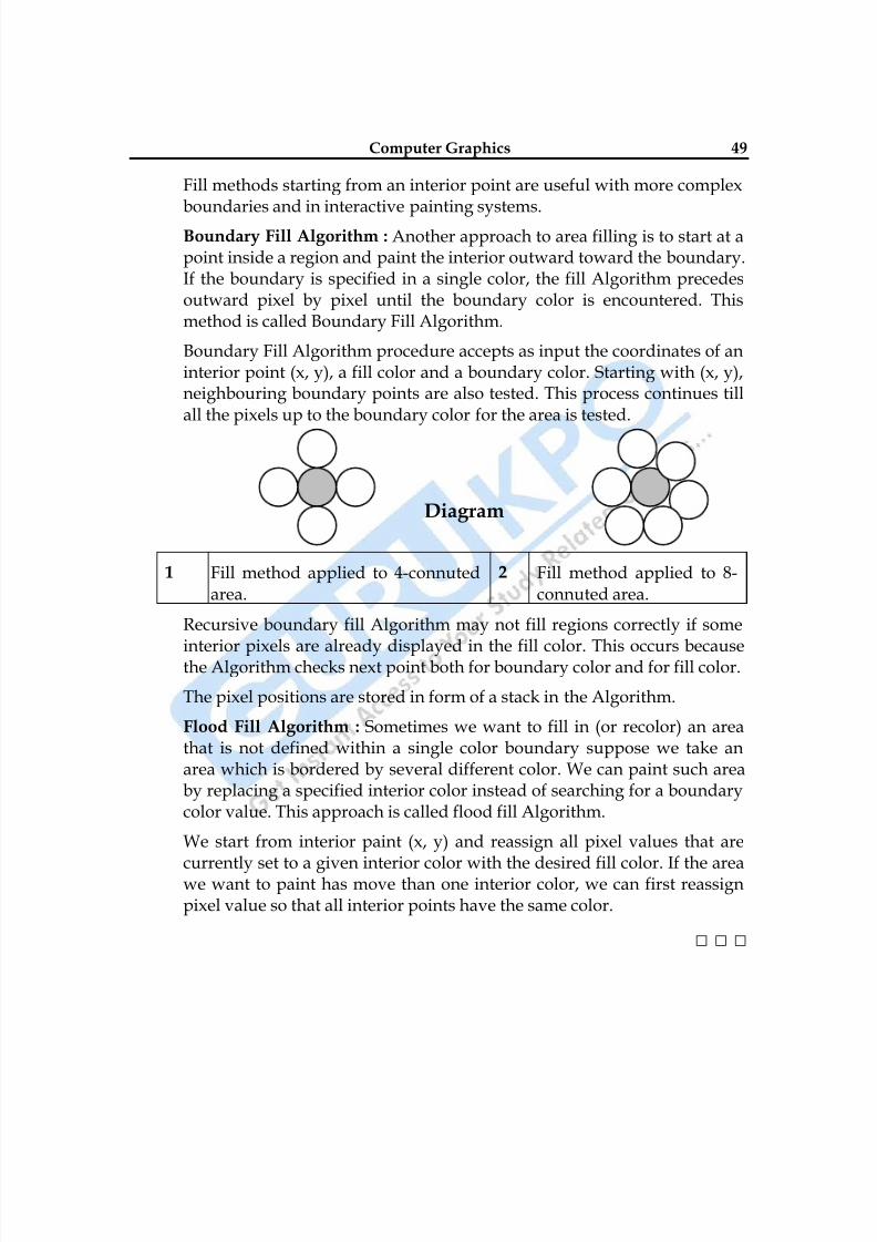
Boundary Fill Algorithm : Another approach to area filling is to start at apoint inside a region and paint the interior outward toward the boundary.If the boundary is specified in a single color, the fill Algorithm precedesoutward pixel by pixel until the boundary color is encountered. Thismethod is called Boundary Fill Algorithm.
Boundary Fill Algorithm procedure accepts as input the coordinates of aninterior point (x, y), a fill color and a boundary color. Starting with (x, y),neighbouring boundary points are also tested. This process continues tillall the pixels up to the boundary color for the area is tested.
Diagram
1 Fill method applied to 4-connutedarea.
2 Fill method applied to 8-connuted area.
Recursive boundary fill Algorithm may not fill regions correctly if some
interior pixels are already displayed in the fill color. This occurs becausethe Algorithm checks next point both for boundary color and for fill color.
The pixel positions are stored in form of a stack in the Algorithm.
Flood Fill Algorithm : Sometimes we want to fill in (or recolor) an areathat is not defined within a single color boundary suppose we take anarea which is bordered by several different color. We can paint such areaby replacing a specified interior color instead of searching for a boundarycolor value. This approach is called flood fill Algorithm.
We start from interior paint (x, y) and reassign all pixel values that are
currently set to a given interior color with the desired fill color. If the areawe want to paint has move than one interior color, we can first reassignpixel value so that all interior points have the same color.
□ □ □
8/10/2019 Computer Graphics & Image Processing
http://slidepdf.com/reader/full/computer-graphics-image-processing 50/117
50
Chapter-4
Clipping Algorithm
Q.1 What is Clipping? How can a point be clipped?
Ans. : Any procedure that identifies those portion of a picture that are either
inside or outside of a specified region of space is referred to as a clippingAlgorithm or clipping. This region against which an object is to be clippedis called a clip window.
Application of Clipping :
(1) Extracting parts of defined scene for veiwing.
(2) Identifying visible surface in three dimentional views.
(3) Antialising line segments or object boundaries.
(4) Creating objects using solid-modeling procedures.
(5)
Displaying multi window environment.
(6) Drawing and painting operations.
Point Clipping : Assuring that clip window is a rectangle in standardPosition, we save a point P = (x, y) for display if following inequalities aresatisfied.
xwmin ≤ x ≤ xwmax
ywmin ≤ y ≤ ywmax
Where the edges of clip window (xwmin, xwmax, ywmin, ywmax) can be
either would coordinate window boundaries or view port boundaries. Ifany one of these inequalities is not satisfied the point is clipped.
8/10/2019 Computer Graphics & Image Processing
http://slidepdf.com/reader/full/computer-graphics-image-processing 51/117
Computer Graphics 51
Application : Point clipping can be applied to scenes involving explosionsor sea foam that are modeled with particles (points) distributed in someregion of the scene.
Q. 2 What is Line Clipping? Explain Cohen Sutherland Method of LineClipping.
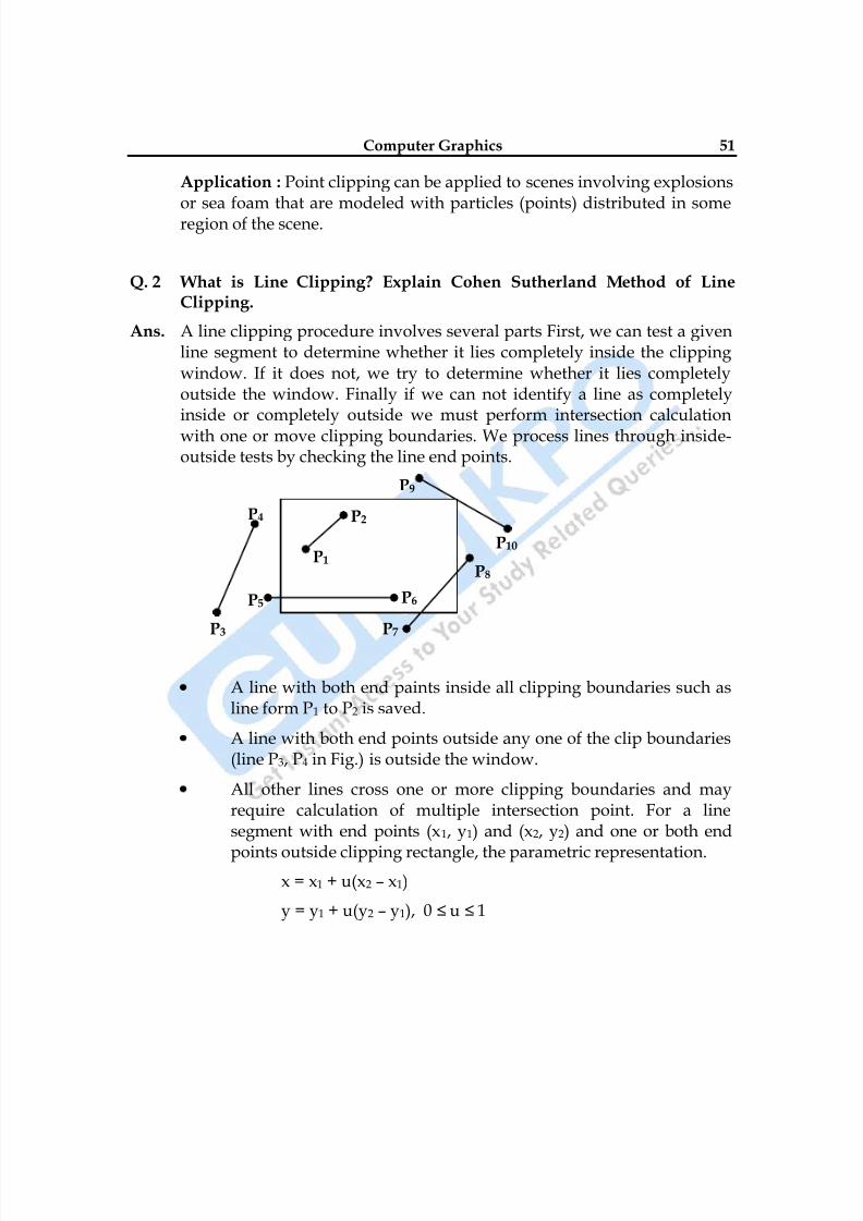
Ans. A line clipping procedure involves several parts First, we can test a given
line segment to determine whether it lies completely inside the clippingwindow. If it does not, we try to determine whether it lies completelyoutside the window. Finally if we can not identify a line as completelyinside or completely outside we must perform intersection calculationwith one or move clipping boundaries. We process lines through inside-outside tests by checking the line end points.
P9
P4
P10
P8
P5 P5
P3 P7
A line with both end paints inside all clipping boundaries such asline form P1 to P2 is saved.
A line with both end points outside any one of the clip boundaries(line P3, P4 in Fig.) is outside the window.
All other lines cross one or more clipping boundaries and mayrequire calculation of multiple intersection point. For a linesegment with end points (x1, y1) and (x2, y2) and one or both end
points outside clipping rectangle, the parametric representation.x = x1 + u(x2 – x1)
y = y1 + u(y2 – y1), 0 ≤ u ≤ 1
P2
P1
P6
8/10/2019 Computer Graphics & Image Processing
http://slidepdf.com/reader/full/computer-graphics-image-processing 52/117
52
Could be used to determine values of parameter u for intersections
with the clipping boundary coordinates. If the value of u for anintersection with a rectangle boundary edge is outside the range 0
to 1, the line does not enter the interior of the window at that
boundary. If the value of u is within the range from 0 to 1, the line
segment does indeed cross into the clipping area.
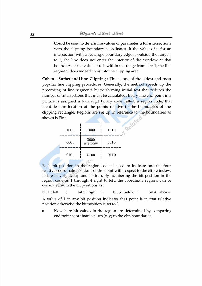
Cohen - SutherlandLline Clipping : This is one of the oldest and most
popular line clipping procedures. Generally, the method speeds up the
processing of line segments by performing initial test that reduces the
number of intersections that must be calculated. Every line end point in a
picture is assigned a four digit binary code called, a region code, thatidentifies the location of the points relative to the boundaries of the
clipping rectangle. Regions are set up in reference to the boundaries as
shown is Fig.:
Each bit position in the region code is used to indicate one the fourrelative coordinate positions of the point with respect to the clip window:to the left, right, top and bottom. By numbering the bit position in theregion code as 1 through 4 right to left, the coordinate regions can becorrelated with the bit positions as :
bit 1 : left ; bit 2 : right ; bit 3 : below ; bit 4 : above
A value of 1 in any bit position indicates that point is in that relativeposition otherwise the bit position is set to 0.
Now here bit values in the region are determined by comparingend point coordinate values (x, y) to the clip boundaries.
1001 1000 1010
0001 0010
0101 0100 0110
0000WINDOW
8/10/2019 Computer Graphics & Image Processing
http://slidepdf.com/reader/full/computer-graphics-image-processing 53/117
Computer Graphics 53
Bit 1 is set to 1 if x < xwmin
Bit 2 is set to 1 it xwmax < x
Now Bit 1 sign bit of x – xwmin
Bit 2 sign bit of xwmax – x
Bit 3 sign bit of y – ywmin
Bit 4 sing bit of ywmax – y
(1) Any lines that are completely inside the clip window have a region
code 0000 for both end points few points to be kept in mind while
checking.(2) Any lines that have 1 in same bit position for both end points are
considered to be completely outside.
(3) Now here we use AND operation with both region codes and if
result is not 0000 then line is completely outside.
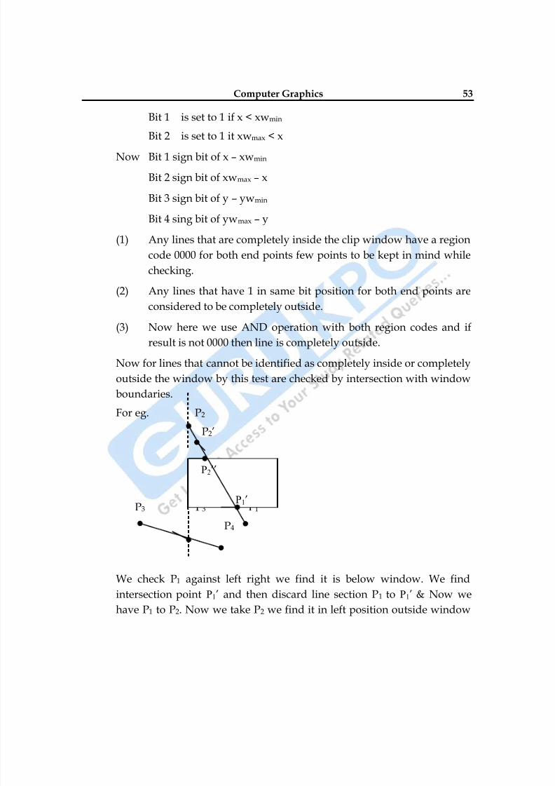
Now for lines that cannot be identified as completely inside or completely
outside the window by this test are checked by intersection with window
boundaries.
For eg. P2
P2‘
P3 P3‘ P1
P4
We check P1 against left right we find it is below window. We find
intersection point P1‘ and then discard line section P1 to P1‘ & Now we
have P1 to P2. Now we take P2 we find it in left position outside window
P2‘‘
P1‘
8/10/2019 Computer Graphics & Image Processing
http://slidepdf.com/reader/full/computer-graphics-image-processing 54/117
54
then we take an intersection point P2‘‘. But we find it outside window
then we again calculate final intersection point P2‘‘. Now we discard lineP2 to P2‘‘. We finally get a line P2‘‘ to P1‘ inside window similarly check for
line P3 to P4.
For end points (x1, y1) (x2, y2) y–coordinate with vertical boundary can becalculated as
y = y1 + m(x – x1) where x is set to xwmin to xwmax
Q.3 Discuss the Cyrus Beck Algorithm for Clipping in a Polygon Window.
Ans. Cyrus Beck Technique : Cyrus Beck Technique can be used to clip a 2–Dline against a rectangle or 3–D line against an arbitrary convex
polyhedron in 3-d space.
Liang Barsky Later developed a more efficient parametric line clipping
Algorithm. Now here we follow Cyrus Beck development to introduce
parametric clipping now in parametric representation of line Algorithm
has a parameter t representation of the line segment for the point at which
that segment intersects the infinite line on which the clip edge lies,
Because all clip edges are in general intersected by the line, four values of
t are calculated. Then a series of comparison are used to check which out
of four values of (t) correspond to actual intersection, only then are the (x,
y) values of two or one actual intersection calculated.
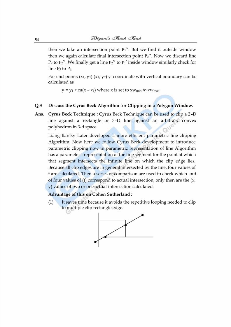
Advantage of this on Cohen Sutherland :
(1) It saves time because it avoids the repetitive looping needed to clipto multiple clip rectangle edge.
8/10/2019 Computer Graphics & Image Processing
http://slidepdf.com/reader/full/computer-graphics-image-processing 55/117
Computer Graphics 55
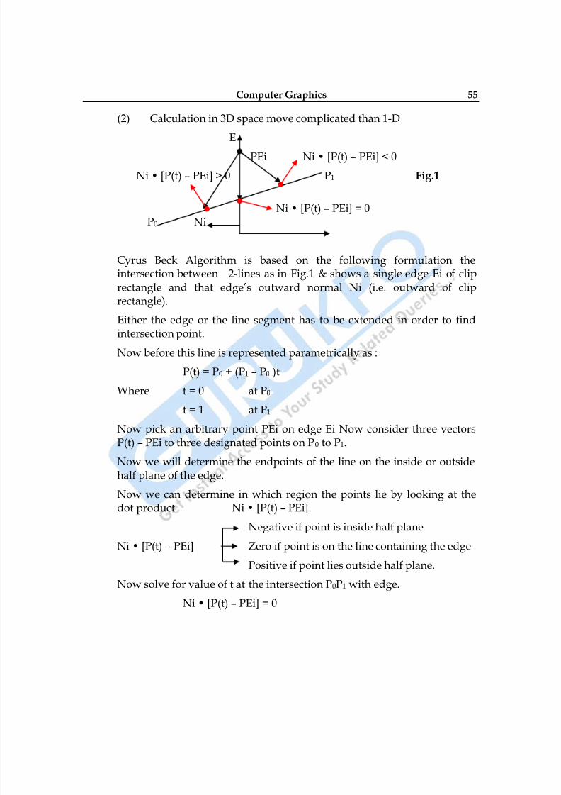
(2) Calculation in 3D space move complicated than 1-D
EPEi Ni • [P(t) – PEi] < 0
Ni • [P(t) – PEi] > 0 P1 Fig.1
Ni • [P(t) – PEi] = 0P0 Ni
Cyrus Beck Algorithm is based on the following formulation the
intersection between 2-lines as in Fig.1 & shows a single edge Ei of cliprectangle and that edge‘s outward normal Ni (i.e. outward of cliprectangle).
Either the edge or the line segment has to be extended in order to findintersection point.
Now before this line is represented parametrically as :
P(t) = P0 + (P1 – P0 )t
Where t = 0 at P0
t = 1 at P1
Now pick an arbitrary point PEi on edge Ei Now consider three vectorsP(t) – PEi to three designated points on P0 to P1.
Now we will determine the endpoints of the line on the inside or outsidehalf plane of the edge.
Now we can determine in which region the points lie by looking at thedot product Ni • [P(t) – PEi].
Negative if point is inside half plane
Ni • [P(t) – PEi] Zero if point is on the line containing the edge
Positive if point lies outside half plane.
Now solve for value of t at the intersection P0P1 with edge.
Ni • [P(t) – PEi] = 0
8/10/2019 Computer Graphics & Image Processing
http://slidepdf.com/reader/full/computer-graphics-image-processing 56/117
56
Substitute for value P(t)
Ni • [P0 + (P1 – P0) t – PEi] = 0Now distribute the product
Ni • [P0 – PEi] + Ni [P1 – P0] t = 0
Let D = (P1 – P0) be the from P0 to P1 and solve for t
t = 0 Ni • [P - PEi]
- Ni • D _ _ _ (1)
This gives a valid value of t only if denominator of the expression is non-zero.
Note : Cyrus Beck use inward Normal Ni, but we prefer to use outwardnormal for consistency with plane normal in 3d which is outward. Ourformulation differs only in testing of a sign.
(1) For this condition of denominator to be non-zero. We check thefollowing :
Ni ≠ 0 (i. e Normal should not be Zero)
D ≠ 0 (i.e P1 ≠ P0)
Now hence Ni • D ≠ 0 (i.e. edge Ei and line between P0 to P1 are notparallel. If they were parallel then there cannot be any intersectionpoint.
Now eq.(1) can be used to find the intersection between the line &the edge.
Now similarly determine normal & an arbitrary PEi say an end ofedge for each clip edge and then find four arbitrary points for the―t‖.
(2) Next step after finding out the four values for ―t‖ is to find outwhich value corresponds to internal intersection of line segment.
(i) Now 1st only value of t outside interval [0, 1] can bediscarded since it lies outside P0P1.
(ii) Next is to determine whether the intersection lies on the clipboundary.
8/10/2019 Computer Graphics & Image Processing
http://slidepdf.com/reader/full/computer-graphics-image-processing 57/117
Computer Graphics 57
P1 (t = 1)
PE P1 (t = 1) P1 (t = 1) PL Line 1 PL PL
P0 PE Line 2 PL
(t = 0) P0 (t = 0) Line 3
PE PE
P0 (t = 0) Fig.2
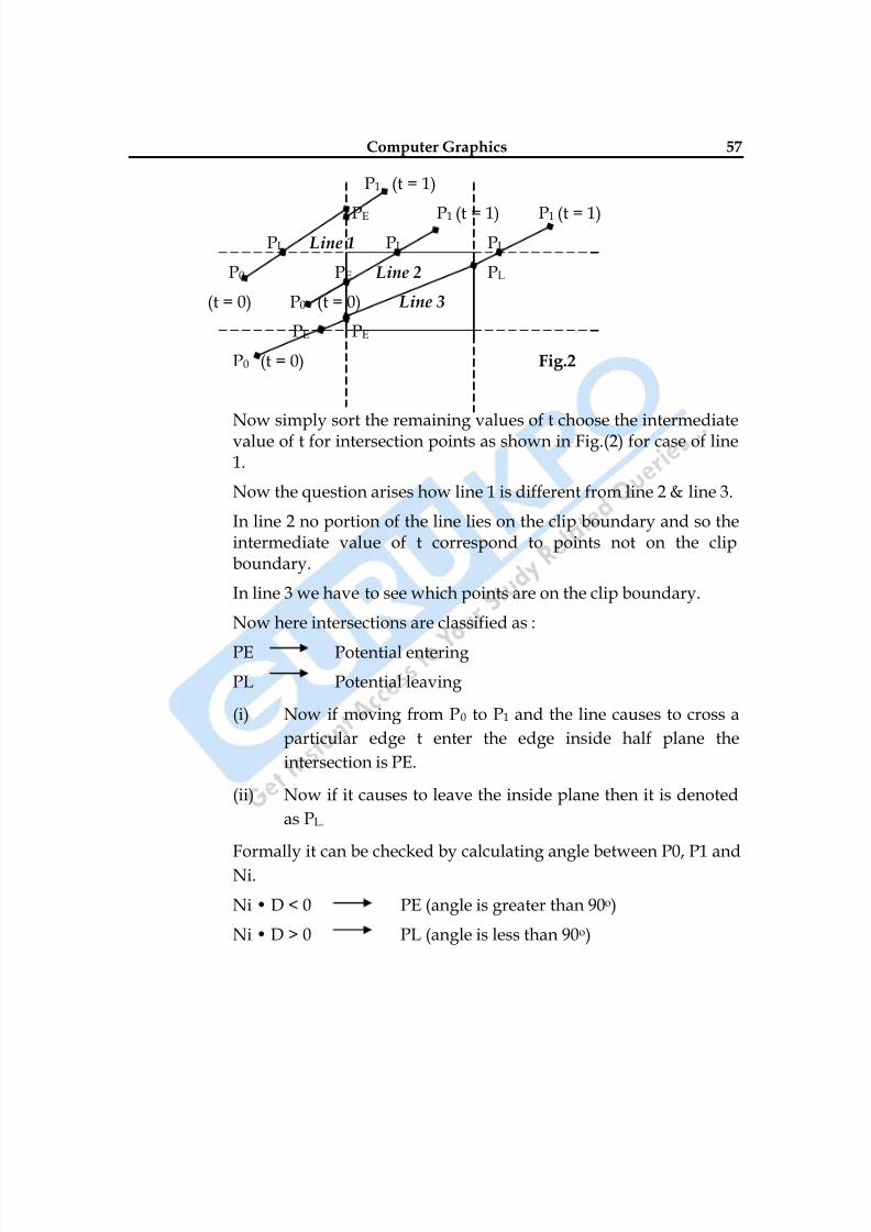
Now simply sort the remaining values of t choose the intermediatevalue of t for intersection points as shown in Fig.(2) for case of line1.
Now the question arises how line 1 is different from line 2 & line 3.
In line 2 no portion of the line lies on the clip boundary and so theintermediate value of t correspond to points not on the clipboundary.
In line 3 we have to see which points are on the clip boundary.
Now here intersections are classified as :
PE Potential entering
PL Potential leaving
(i) Now if moving from P0 to P1 and the line causes to cross a
particular edge t enter the edge inside half plane the
intersection is PE.
(ii) Now if it causes to leave the inside plane then it is denoted
as PL.
Formally it can be checked by calculating angle between P0, P1 and
Ni.
Ni • D < 0 PE (angle is greater than 90o)
Ni • D > 0 PL (angle is less than 90o)
8/10/2019 Computer Graphics & Image Processing
http://slidepdf.com/reader/full/computer-graphics-image-processing 58/117
58
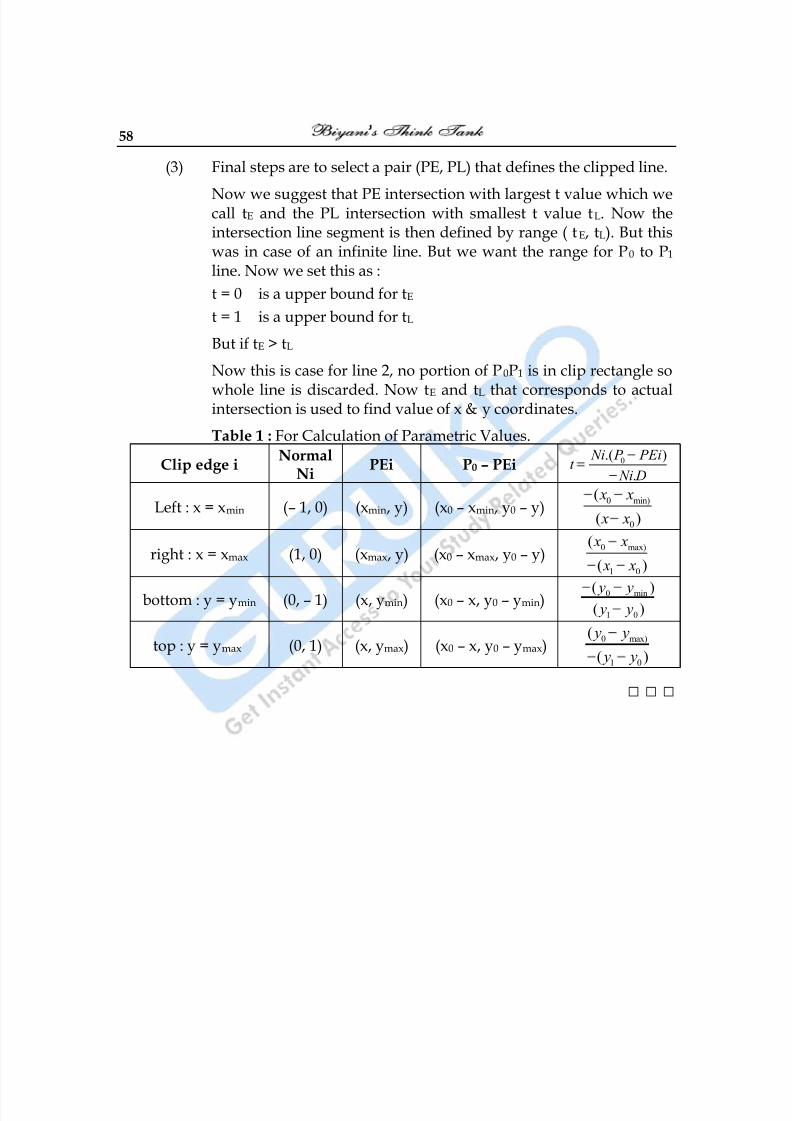
(3) Final steps are to select a pair (PE, PL) that defines the clipped line.
Now we suggest that PE intersection with largest t value which wecall tE and the PL intersection with smallest t value tL. Now theintersection line segment is then defined by range ( tE, tL). But thiswas in case of an infinite line. But we want the range for P0 to P1 line. Now we set this as :
t = 0 is a upper bound for tE
t = 1 is a upper bound for tL
But if tE > tL
Now this is case for line 2, no portion of P0P1 is in clip rectangle so
whole line is discarded. Now tE and tL that corresponds to actualintersection is used to find value of x & y coordinates.
Table 1 : For Calculation of Parametric Values.
Clip edge iNormal
NiPEi P0 – PEi 0.( )
.
Ni P PEit
Ni D
Left : x = xmin (– 1, 0) (xmin, y) (x0 – xmin, y0 – y)0 min)
0
(
( )
x x
x x
right : x = xmax (1, 0) (xmax, y) (x0 – xmax, y0 – y)0 max)
1 0
(
( )
x x
x x
bottom : y = ymin (0, – 1) (x, ymin) (x0 – x, y0 – ymin)0 min
1 0
( )( ) y y y y
top : y = ymax (0, 1) (x, ymax) (x0 – x, y0 – ymax)0 max)
1 0
(
( )
y y
y y
□ □ □
8/10/2019 Computer Graphics & Image Processing
http://slidepdf.com/reader/full/computer-graphics-image-processing 59/117
Computer Graphics 59
Chapter-5
Visible Surface Detection
Q.1 Explain the Depth Buffer Method in detail or Z–Buffer Method.
Ans.: This is commonly used image space approach to detecting visible surfaces
is the depth buffer method, which compares surface depths at each pixelposition on the projection plane. This procedure is referred to as the z-
buffer method since object depth is usefully me as used from the view
plane along z-axis of the viewing system. Each surface of a scene is
processed separately, one point at a time across the surface. This method
is mainly applied to scenes containing only polygon surfaces, because
depth values can be computed very quickly and method is easy to
implement.
With object descriptions converted to projection coordinates, each (x, y, z)
position on the polygon surface corresponds to the orthographic
projection point (x, y) on the view plane. Therefore, for each pixel
position(x, y) on the view plane, object depths can be compared by
comparing z-values.
This Fig.(1) shows three surfaces at varying distances along the
orthographic projection line form position (x, y) in a view plane taken as
xvyv plane. Surface S1 is closest at this position, so its surface intensity
value at (x, y) is saved.
As implied by name of this method, two buffer areas are required. Adepth buffer is used to store depth values for each (x, y) position assurfaces are processed and the refresh buffer stores the intensity valuesfor each position.
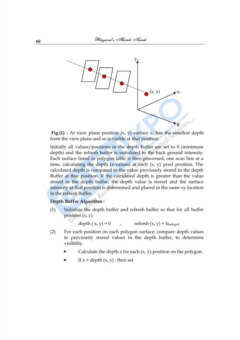
8/10/2019 Computer Graphics & Image Processing
http://slidepdf.com/reader/full/computer-graphics-image-processing 60/117
60
yv
(x, y) xv
z
Fig.(1) : At view plane position (x, y) surface s1 has the smallest depthform the view plane and so is visible at that position.
Initially all values/positions in the depth buffer are set to 0 (minimumdepth) and the refresh buffer is initialized to the back ground intensity.Each surface listed in polygon table is then processed, one scan line at atime, calculating the depth (z-values) at each (x, y) pixel position. Thecalculated depth is compared to the value previously stored in the depthBuffer at that position. If the calculated depth is greater than the valuestored in the depth buffer, the depth value is stored and the surfaceintensity at that position is determined and placed in the same xy locationin the refresh Buffer.
Depth Buffer Algorithm :
(1) Initialize the depth buffer and refresh buffer so that for all bufferposition (x, y).
depth ( x, y) = 0 , refresh (x, y) = IBackgnd
(2) For each position on each polygon surface, compare depth values
to previously stored values in the depth buffer, to determinevisibility.
Calculate the depth z for each (x, y) position on the polygon.
If z > depth (x, y) : then set
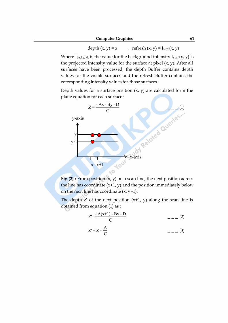
8/10/2019 Computer Graphics & Image Processing
http://slidepdf.com/reader/full/computer-graphics-image-processing 61/117
Computer Graphics 61
depth (x, y) = z , refresh (x, y) = Isurf.(x, y)
Where Ibackgnd. is the value for the background intensity Isurf.(x, y) isthe projected intensity value for the surface at pixel (x, y). After all
surfaces have been processed, the depth Buffer contains depth
values for the visible surfaces and the refresh Buffer contains the
corresponding intensity values for those surfaces.
Depth values for a surface position (x, y) are calculated form the
plane equation for each surface :
- Ax - By - D
C Z _ _ _ (1)
y-axis
y
y-1
x-axis
x x+1
Fig.(2) : From position (x, y) on a scan line, the next position across
the line has coordinate (x+1, y) and the position immediately below
on the next line has coordinate (x, y–1).
The depth z‘ of the next position (x+1, y) along the scan line is
obtained from equation (1) as :
- A(x+1) - By - DZ'=
C _ _ _ (2)
AZ' = Z -
C _ _ _ (3)
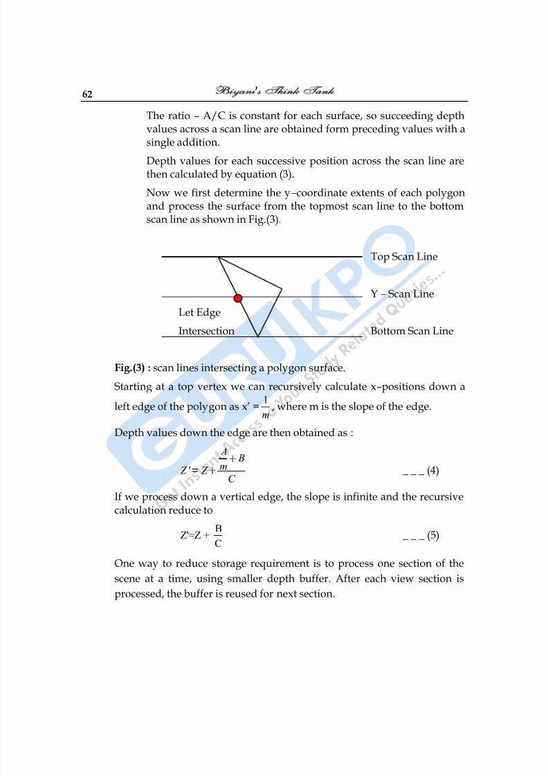
8/10/2019 Computer Graphics & Image Processing
http://slidepdf.com/reader/full/computer-graphics-image-processing 62/117
62
The ratio – A/C is constant for each surface, so succeeding depthvalues across a scan line are obtained form preceding values with asingle addition.
Depth values for each successive position across the scan line arethen calculated by equation (3).
Now we first determine the y–coordinate extents of each polygonand process the surface from the topmost scan line to the bottomscan line as shown in Fig.(3).
Top Scan Line
Y – Scan Line
Let Edge
Intersection Bottom Scan Line
Fig.(3) : scan lines intersecting a polygon surface.
Starting at a top vertex we can recursively calculate x–positions down a
left edge of the polygon as x‘ =1
m , where m is the slope of the edge.
Depth values down the edge are then obtained as :
'
A B
m Z Z C
_ _ _ (4)
If we process down a vertical edge, the slope is infinite and the recursivecalculation reduce to
BZ'=Z +
C
_ _ _ (5)
One way to reduce storage requirement is to process one section of the
scene at a time, using smaller depth buffer. After each view section is
processed, the buffer is reused for next section.
8/10/2019 Computer Graphics & Image Processing
http://slidepdf.com/reader/full/computer-graphics-image-processing 63/117
Computer Graphics 63
Q.2 How is Depth Buffer Method different form A Buffer Method?
Ans.:S.No. Z – Buffer Method A – Buffer Method
1. In Z–Buffer method alphabetZ – represents depth.
The A–Buffer methodrepresents an antialised, areaaveraged, accumulation Buffermethod.
2. It can find only one visiblesurface at each pixel position
that is it deals only withopaque surfaces.
In this each position in thebuffer can reference a linked
list of surfaces.
3. This can‘t accumulateintensity values for more thanone surface.
More than one surface intensitycan be taken into considerationat each pixel position.
Q.3 What is Object Space Method of Visible Surface Detection?
Ans.: Visible surface detection algorithm is broadly classified according to
whether they deal with object definitions directly or with their projectedImages. These two approaches are called.
object – space methods
Image – space methods.
An object – space method compares objects and parts of objects to each
other within the scheme definition to determine which surfaces, as a
whole, we should label as visible.
Object space methods can be used effectively to locate visible surfaces in
some cases.Line display algorithm uses object space method to identify visible lines
in wire frame displays.
8/10/2019 Computer Graphics & Image Processing
http://slidepdf.com/reader/full/computer-graphics-image-processing 64/117
64
Q. 4 Differentiate between Object Space Method and Image Space Method?
Ans.:S.No. Z – Buffer Method A – Buffer Method
1. This method deals with objectdefinition directly
This method deals with theirprojected Images.
2. This method compares objectsand parts of objects to eachother within the scenedefinition.
In this visibility is decidedpoint by point at each pixelposition on the projectionplane.
3. This method can be used
effectively to locate visiblesurfaces in some cases.
Most visible surfaces use this
Method.
Q.5 Explain Painter’s Algorithm for removing hidden surfaces?
Ans.: Depth sorting methods for solving hidden surface problem is oftenrefered to as Painter‘s Algorithm.
Now using both image space and object space operations, the depthsorting method performs following basic functions :
(1) Surfaces are sorted in order of decreasing depth.
(2)
Surfaces are scan consented in order, starting with the surface ofgreatest depth.
Sorting operations carried out in both image and object space, the scanconversion of the polygon surface is performed in image space.
For e.g. : In creating an oil painting, an artist first paints the backgroundcolors. Next the most distant objects are added, then the nearer objectsand so forth. At the final step, the foreground objects are painted on thecanvas over the Background and other objects that have been painted onthe canvas. Each layer of paint covers up the previous layer using similartechnique, we first of sort surfaces according to their distances form view
plane. The intensity value for the farthest surface are then entered into therefresh Buffer. Taking each succeeding surface in turn (in decreasingdepth) we paint the surface intensities onto the frame buffer over theintensities of the previously processed surfaces.
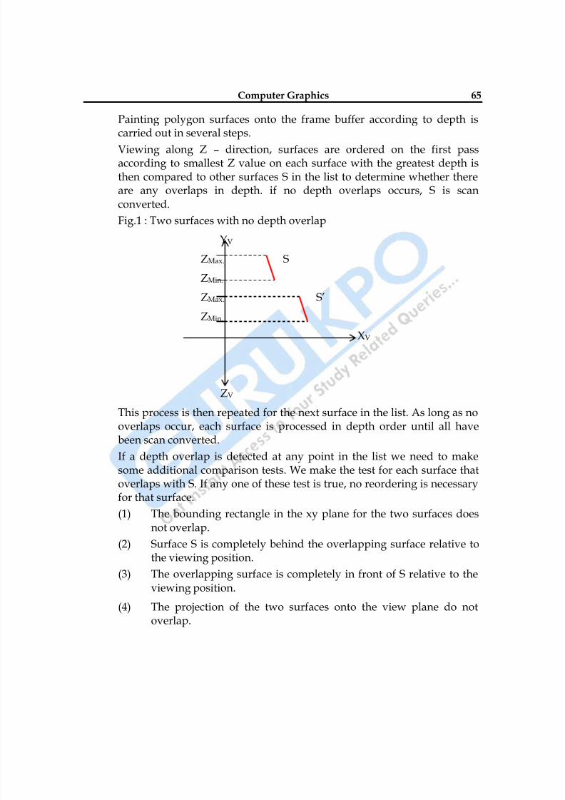
8/10/2019 Computer Graphics & Image Processing
http://slidepdf.com/reader/full/computer-graphics-image-processing 65/117
Computer Graphics 65
Painting polygon surfaces onto the frame buffer according to depth iscarried out in several steps.
Viewing along Z – direction, surfaces are ordered on the first passaccording to smallest Z value on each surface with the greatest depth isthen compared to other surfaces S in the list to determine whether thereare any overlaps in depth. if no depth overlaps occurs, S is scanconverted.
Fig.1 : Two surfaces with no depth overlap
YV
ZMax. S
ZMin.
ZMax. S‘
ZMin.
XV
ZV
This process is then repeated for the next surface in the list. As long as nooverlaps occur, each surface is processed in depth order until all havebeen scan converted.
If a depth overlap is detected at any point in the list we need to makesome additional comparison tests. We make the test for each surface thatoverlaps with S. If any one of these test is true, no reordering is necessaryfor that surface.
(1) The bounding rectangle in the xy plane for the two surfaces doesnot overlap.
(2) Surface S is completely behind the overlapping surface relative to
the viewing position.(3) The overlapping surface is completely in front of S relative to the
viewing position.
(4) The projection of the two surfaces onto the view plane do notoverlap.
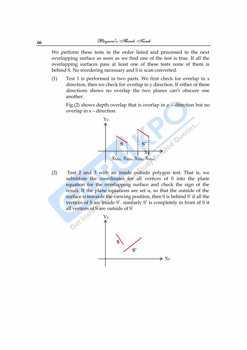
8/10/2019 Computer Graphics & Image Processing
http://slidepdf.com/reader/full/computer-graphics-image-processing 66/117
66
We perform these tests in the order listed and processed to the nextoverlapping surface as soon as we find one of the test is true. If all theoverlapping surfaces pass at least one of these tests none of them isbehind S. No reordering necessary and S is scan converted.
(1) Test 1 is performed in two parts. We first check for overlap in xdirection, then we check for overlap in y direction. If either of thesedirections shows no overlap the two planes can‘t obscure oneanother.
Fig.(2) shows depth overlap that is overlap in z – direction but nooverlap in x – direction.
YV
S S’
XV
XMin. XMax. XMin. XMax.
(2) Test 2 and 3 with an inside outside polygon test. That is, wesubstitute the coordinates for all vertices of S into the plane
equation for the overlapping surface and check the sign of theresult. If the plane equations are set u, so that the outside of thesurface is towards the viewing position, then S is behind S‘ if all thevertices of S are inside S‘. similarly S‘ is completely in front of S itall vertices of S are outside of S‘
YV
S
S’
XV
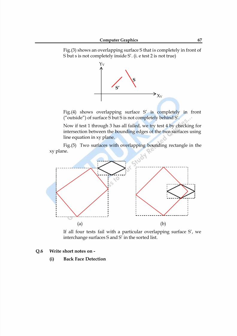
8/10/2019 Computer Graphics & Image Processing
http://slidepdf.com/reader/full/computer-graphics-image-processing 67/117
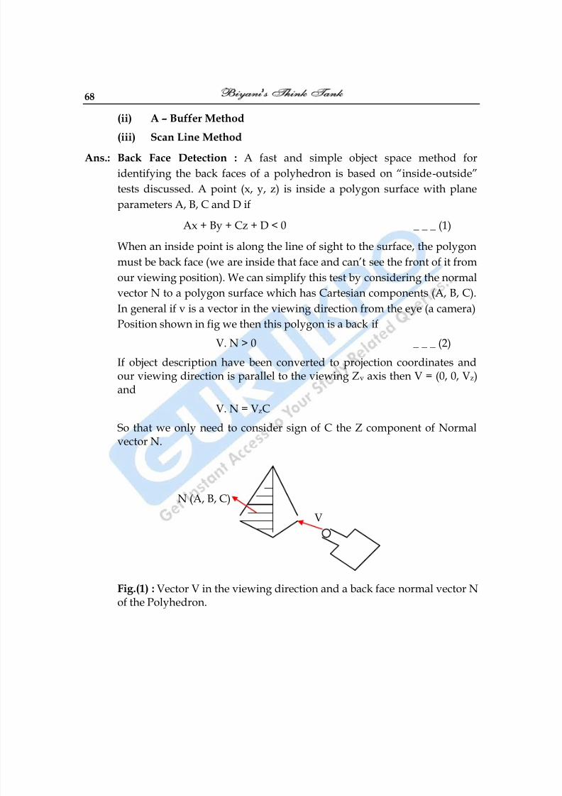
8/10/2019 Computer Graphics & Image Processing
http://slidepdf.com/reader/full/computer-graphics-image-processing 68/117
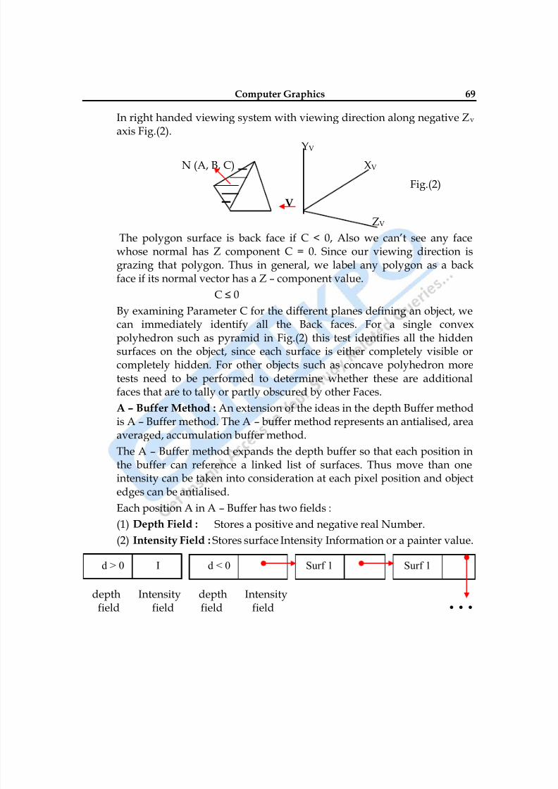
8/10/2019 Computer Graphics & Image Processing
http://slidepdf.com/reader/full/computer-graphics-image-processing 69/117
Computer Graphics 69
In right handed viewing system with viewing direction along negative Zv axis Fig.(2).
YV
N (A, B, C) XV
Fig.(2)
V
ZV
The polygon surface is back face if C < 0, Also we can‘t see any facewhose normal has Z component C = 0. Since our viewing direction isgrazing that polygon. Thus in general, we label any polygon as a back
face if its normal vector has a Z – component value.C ≤ 0
By examining Parameter C for the different planes defining an object, wecan immediately identify all the Back faces. For a single convexpolyhedron such as pyramid in Fig.(2) this test identifies all the hiddensurfaces on the object, since each surface is either completely visible orcompletely hidden. For other objects such as concave polyhedron moretests need to be performed to determine whether these are additionalfaces that are to tally or partly obscured by other Faces.
A – Buffer Method : An extension of the ideas in the depth Buffer methodis A – Buffer method. The A – buffer method represents an antialised, areaaveraged, accumulation buffer method.
The A – Buffer method expands the depth buffer so that each position inthe buffer can reference a linked list of surfaces. Thus move than oneintensity can be taken into consideration at each pixel position and objectedges can be antialised.
Each position A in A – Buffer has two fields :
(1) Depth Field : Stores a positive and negative real Number.
(2) Intensity Field : Stores surface Intensity Information or a painter value.
depth Intensity depth Intensityfield field field field • • •
d > 0 I d < 0 Surf 1 Surf 1
8/10/2019 Computer Graphics & Image Processing
http://slidepdf.com/reader/full/computer-graphics-image-processing 70/117
70
Fig.(1) organization of A – Buffer pixel position :
(a)
Shows single surface overlap of corresponding pixel area.(b) Shows multiple surface overlap.
If the depth field is positive, the member stored at that position is thedepth of a single surface overlapping the corresponding pixel area. Theintensity field then stores RGB components of surface color at that pointand the percentage of pixel coverage as shown in Fig.(1).
Data for each surface in the linked list includes :
1) RGB Intensity Component 5) Surface Identifier
2) Opacity Parameter 6) Other Surface Rendering Parameter3) Depth 7) Pointer to Next Surface
4) Percent of Area Coverage
Scan – Line Method : The image space method for removing hiddensurfaces is a extension of the scan line Algorithm for filling Polygoninterior of filling first one surface we now deal with the multiple surfaces.As each scan line is processed, all Polygon surfaces intersecting that lineare examined to determine which are visible. Across each scan line depthcalculations are made for each overlapping surface to determine which is
nearest to the view plane. When the visible surface has been determined,the intensity value for that position is entered into the refresh Buffer.
Two tables are used for various surfaces :
(i) Edge Table (ii) Polygon Table
Edge Table : contains coordinate end points for each line in the scene, theinverse slope of each line and pointers into the polygon table to identifythe surface bounded by each line.
Polygon Table : Contains coefficient of the plane equation for eachsurface, intensity information for the surfaces and possible pointers into
the edge table.
□ □ □
8/10/2019 Computer Graphics & Image Processing
http://slidepdf.com/reader/full/computer-graphics-image-processing 71/117
Computer Graphics 71
Chapter-6
Curves and Surfaces
Q.1 What are Bezier Curves and Surfaces. Write the properties of Bezier
Curves.
Ans.: This spline approximation method was developed by French Engineer
Pierre Bezier for use in the design of Renault automobile bodies Bezier
splines have a number of properties that make them highly useful and
convenient for curves and surface design. They are easy to implement.
Bezier splines are widely available in CAD systems.
Bezier Curves : A Bezier curve can be fitted to any number of control
points. The number of control point to be approximated and their relative
position determine the degree of Bezier polynomial. As with interpolationsplines, a Bezier curve can be specified with boundary conditions, with
characterizing matrix or with blending functions.
Suppose we have (n + 1) control point positions: Pk – (xk, yk, zk,) with K
varying from 0 to n. These coordinate points can be blended to produce
the following position vector P(u), which describes the path of an
approximating Bezier Polynomial function between P0 & Pn.
n
P (u) = ∑ Pk BEZ k,n (u) 0 ≤ u ≤ 1 _ _ _ (1)
K = 0
The Bezier blending functions BEZk,n (u) are the Bernstein polynomial.
BEZk,n(u) = C (n, k) uk (1 – u) n-k _ _ _ (2)
Where C(n,k) are the binomial coefficients
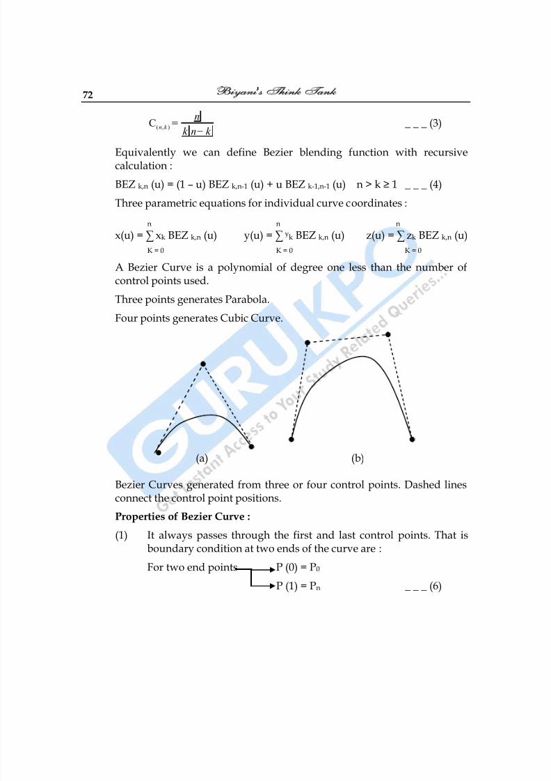
8/10/2019 Computer Graphics & Image Processing
http://slidepdf.com/reader/full/computer-graphics-image-processing 72/117
72
( , )C n k
n
k n k
_ _ _ (3)
Equivalently we can define Bezier blending function with recursivecalculation :
BEZ k,n (u) = (1 – u) BEZ k,n-1 (u) + u BEZ k-1,n-1 (u) n > k ≥ 1 _ _ _ (4)
Three parametric equations for individual curve coordinates :
n n n
x(u) = ∑ xk BEZ k,n (u) y(u) = ∑ yk BEZ k,n (u) z(u) = ∑ zk BEZ k,n (u)
K = 0 K = 0 K = 0
A Bezier Curve is a polynomial of degree one less than the number ofcontrol points used.
Three points generates Parabola.
Four points generates Cubic Curve.
(a) (b)
Bezier Curves generated from three or four control points. Dashed linesconnect the control point positions.
Properties of Bezier Curve :
(1) It always passes through the first and last control points. That is
boundary condition at two ends of the curve are :
For two end points P (0) = P0
P (1) = Pn _ _ _ (6)
8/10/2019 Computer Graphics & Image Processing
http://slidepdf.com/reader/full/computer-graphics-image-processing 73/117
Computer Graphics 73
Now value for the first derivative of a Bezier Curve at the endpoints can be calculated from control point coordinates as :
P‘(0) = - nP0 +nP1 First derivative for the
P‘(1) = - nPn-1 + nPn first & last 2 end points _ _ _ (7)
Slope of the curve at the beginning of curve is calculated by joining the beginning 2- points.
Slope of the curve at the end of curve is calculated by joining the 2– end points.
Similarly second derivative of Bezier Curve at the end point are : -
P‘‘(0) = n (n – 1) [(P2 – P1) – (P1 – P0)]
P‘‘(1) = n (n – 1) [ (Pn–2 – Pn–1) – (Pn–1 – Pn)] _ _ _ (8)
(2) Another property of Bezier Curve is, it lies within the convex hull.Therefore this follows the properties of Bezier blending function.That is they are all positive & their sum is always 1.
n
∑ BEZ k,n (u) = 1 _ _ _ (9)
K = 0
So that any curve position is simply weighted sum of the controlpoints positions.
The convex hull also ensures that polynomial smoothly follows thecontrol points without erratic oscillations.
Bezier Surfaces : Two sets of orthogonal Bezier Curves can be used todesign an object surface by specifying by an input mesh of control points.
Blending function are :
m n
P(u, v) = ∑ ∑ P j,k BEZ j,m (v) BEZk,n (u) _ _ _ (10)
j = 0 k=0
With P j,k specifying location of (m + 1) by (n + 1) control points.
Bezier surfaces have same properties as Bezier Curves. Zero ordercontinuity is obtained by matching control points at the boundary.
8/10/2019 Computer Graphics & Image Processing
http://slidepdf.com/reader/full/computer-graphics-image-processing 74/117
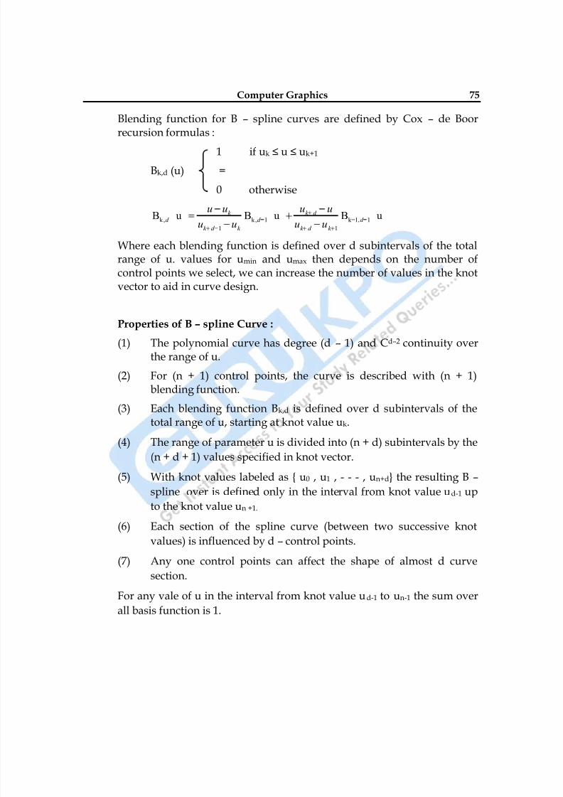
8/10/2019 Computer Graphics & Image Processing
http://slidepdf.com/reader/full/computer-graphics-image-processing 75/117
Computer Graphics 75
Blending function for B – spline curves are defined by Cox – de Boorrecursion formulas :
1 if uk ≤ u ≤ uk+1
Bk,d (u) =
0 otherwise
k, k, 1 k=1, 1
1 1
B u B u B uk k d d d d
k d k k d k
u u u u
u u u u
Where each blending function is defined over d subintervals of the totalrange of u. values for umin and umax then depends on the number of
control points we select, we can increase the number of values in the knotvector to aid in curve design.
Properties of B – spline Curve :
(1) The polynomial curve has degree (d – 1) and Cd–2 continuity overthe range of u.
(2) For (n + 1) control points, the curve is described with (n + 1)blending function.
(3) Each blending function Bk,d is defined over d subintervals of the
total range of u, starting at knot value uk.
(4) The range of parameter u is divided into (n + d) subintervals by the
(n + d + 1) values specified in knot vector.
(5) With knot values labeled as { u0 , u1 , - - - , un+d} the resulting B –
spline over is defined only in the interval from knot value ud-1 up
to the knot value un +1.
(6) Each section of the spline curve (between two successive knot
values) is influenced by d – control points.
(7)
Any one control points can affect the shape of almost d curvesection.
For any vale of u in the interval from knot value ud-1 to un-1 the sum over
all basis function is 1.
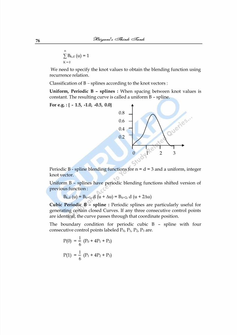
8/10/2019 Computer Graphics & Image Processing
http://slidepdf.com/reader/full/computer-graphics-image-processing 76/117
76
n
∑ Bk,d (u) = 1
K = 0
We need to specify the knot values to obtain the blending function usingrecurrence relation.
Classification of B – splines according to the knot vectors :
Uniform, Periodic B – splines : When spacing between knot values isconstant. The resulting curve is called a uniform B – spline.
For e.g. : { - 1.5, -1.0, -0.5, 0.0}
0.8
0.6
0.4
0.2
0 1 2 3
Periodic B - spline blending functions for n = d = 3 and a uniform, integer
knot vector.Uniform B – splines have periodic blending functions shifted version ofprevious function :
Bk,d (u) = Bk+1, d (u + ∆u) = Bk+2, d (u + 2∆u)
Cubic Periodic B – spline : Periodic splines are particularly useful forgenerating certain closed Curves. If any three consecutive control pointsare identical, the curve passes through that coordinate position.
The boundary condition for periodic cubic B – spline with fourconsecutive control points labeled P0, P1, P2, P3 are.
P(0) =1
6 (P0 + 4P1 + P2)
P(1) =1
6 (P1 + 4P2 + P3)
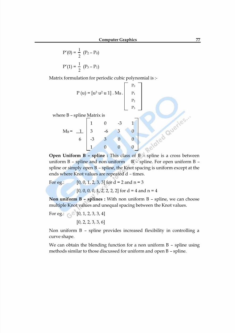
8/10/2019 Computer Graphics & Image Processing
http://slidepdf.com/reader/full/computer-graphics-image-processing 77/117
Computer Graphics 77
P‘(0) =1
2
(P2 – P0)
P‘(1) =1
2 (P3 – P1)
Matrix formulation for periodic cubic polynomial is :-
P0
P (u) = [u3 u2 u 1] . MB . P1
P2
P3
where B – spline Matrix is1 0 -3 1
MB = 1 3 -6 3 0
6 -3 3 0 0
1 0 0 0
Open Uniform B – spline : This class of B – spline is a cross between
uniform B – spline and non uniform B – spline. For open uniform B –
spline or simply open B – spline, the Knot spacing is uniform except at the
ends where Knot values are repeated d – times.For eg.: [0, 0, 1, 2, 3, 3] for d = 2 and n = 3
[0, 0, 0, 0, 1, 2, 2, 2, 2] for d = 4 and n = 4
Non uniform B – splines : With non uniform B – spline, we can choose
multiple Knot values and unequal spacing between the Knot values.
For eg.: [0, 1, 2, 3, 3, 4]
[0, 2, 2, 3, 3, 6]
Non uniform B – spline provides increased flexibility in controlling a
curve shape.
We can obtain the blending function for a non uniform B – spline using
methods similar to those discussed for uniform and open B – spline.
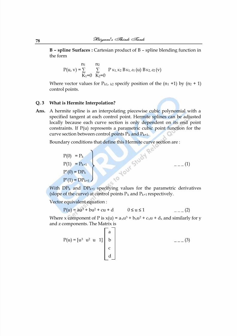
8/10/2019 Computer Graphics & Image Processing
http://slidepdf.com/reader/full/computer-graphics-image-processing 78/117
78
B – spline Surfaces : Cartesian product of B – spline blending function inthe form
n1 n2 P(u, v) = ∑ ∑ P K1, K2 B K1, d1 (u) B K2, d2 (v)
K1=0 K2=0
Where vector values for Pk1, k2 specify position of the (n1 +1) by (n2 + 1)control points.
Q. 3 What is Hermite Interpolation?
Ans. A hermite spline is an interpolating piecewise cubic polynomial with a
specified tangent at each control point. Hermite splines can be adjustedlocally because each curve section is only dependent on its end pointconstraints. If P(u) represents a parametric cubic point function for thecurve section between control points Pk and Pk+1.
Boundary conditions that define this Hermite curve section are :
P(0) = Pk
P(1) = Pk+1 _ _ _ (1)
P‘(0) = DPk
P‘(1) = DPk+1
With DPk and DPk+1 specifying values for the parametric derivatives(slope of the curve) at control points Pk and Pk+1 respectively.
Vector equivalent equation :
P(u) = au3 + bu2 + cu + d 0 ≤ u ≤ 1 _ _ _ (2)
Where x component of P is x(u) = axu3 + bxu2 + cxu + dx and similarly for yand z components. The Matrix is
a
P(u) = [u3 u2 u 1] b _ _ _ (3)
c
d
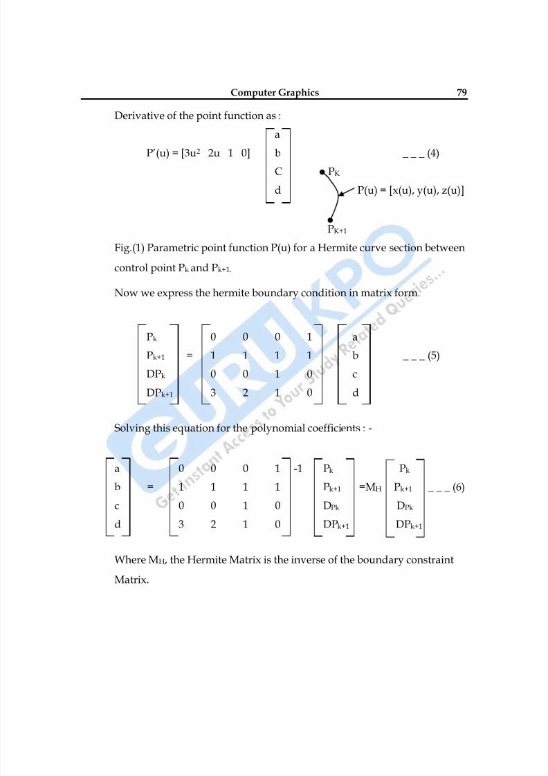
8/10/2019 Computer Graphics & Image Processing
http://slidepdf.com/reader/full/computer-graphics-image-processing 79/117
Computer Graphics 79
Derivative of the point function as :
aP‘(u) = [3u2 2u 1 0] b _ _ _ (4)
C PK
d P(u) = [x(u), y(u), z(u)]
PK+1
Fig.(1) Parametric point function P(u) for a Hermite curve section between
control point Pk and Pk+1.
Now we express the hermite boundary condition in matrix form.
Pk 0 0 0 1 a
Pk+1 = 1 1 1 1 b _ _ _ (5)
DPk 0 0 1 0 c
DPk+1 3 2 1 0 d
Solving this equation for the polynomial coefficients : -
a 0 0 0 1 -1 Pk Pk
b = 1 1 1 1 Pk+1 =MH Pk+1 _ _ _ (6)
c 0 0 1 0 DPk DPk
d 3 2 1 0 DPk+1 DPk+1
Where MH, the Hermite Matrix is the inverse of the boundary constraint
Matrix.
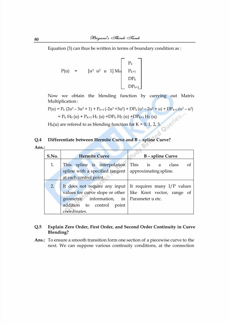
8/10/2019 Computer Graphics & Image Processing
http://slidepdf.com/reader/full/computer-graphics-image-processing 80/117
80
Equation (3) can thus be written in terms of boundary condition as :
Pk
P(u) = [u3 u2 u 1] MH Pk+1
DPk
DPk+1
Now we obtain the blending function by carrying out MatrixMultiplication :
P(u) = Pk (2u3 – 3u2 + 1) + Pk+1 (-2u3 +3u2) + DPk (u3 – 2u2 + u) + DPk+1 (u3 – u2)
= Pk H0 (u) + Pk+1 H1 (u) +DPk H2 (u) +DPk+1 H3 (u)
Hk(u) are refered to as blending function for K = 0, 1, 2, 3.
Q.4 Differentiate between Hermite Curve and B - spline Curve?
Ans.:
S.No. Hermite Curve B – spline Curve
1. This spline is interpolation
spline with a specified tangentat each control point.
This is a class of
approximating spline.
2. It does not require any input
values for curve slope or other
geometric information, in
addition to control point
coordinates.
It requires many I/P values
like Knot vector, range of
Parameter u etc.
Q.5 Explain Zero Order, First Order, and Second Order Continuity in CurveBlending?
Ans.: To ensure a smooth transition form one section of a piecewise curve to thenext. We can suppose various continuity conditions, at the connection
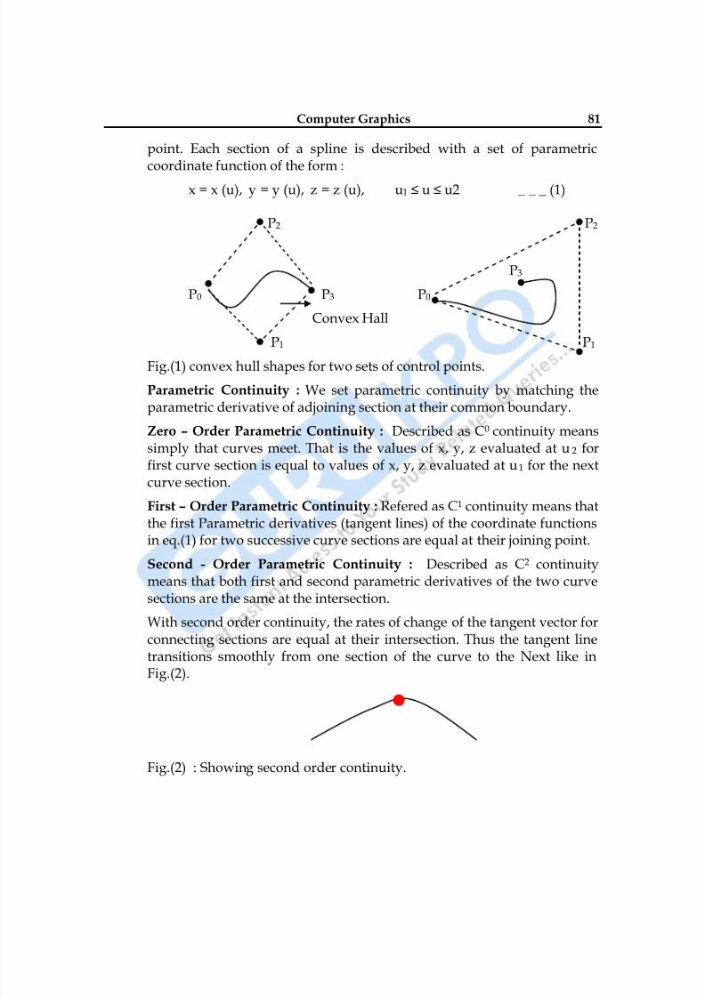
8/10/2019 Computer Graphics & Image Processing
http://slidepdf.com/reader/full/computer-graphics-image-processing 81/117
Computer Graphics 81
point. Each section of a spline is described with a set of parametriccoordinate function of the form :
x = x (u), y = y (u), z = z (u), u1 ≤ u ≤ u2 _ _ _ (1)
P2 P2
P3
P0 P3 P0
Convex Hall
P1 P1 Fig.(1) convex hull shapes for two sets of control points.
Parametric Continuity : We set parametric continuity by matching theparametric derivative of adjoining section at their common boundary.
Zero – Order Parametric Continuity : Described as C0 continuity meanssimply that curves meet. That is the values of x, y, z evaluated at u 2 forfirst curve section is equal to values of x, y, z evaluated at u 1 for the nextcurve section.
First – Order Parametric Continuity : Refered as C1 continuity means that
the first Parametric derivatives (tangent lines) of the coordinate functionsin eq.(1) for two successive curve sections are equal at their joining point.
Second - Order Parametric Continuity : Described as C2 continuitymeans that both first and second parametric derivatives of the two curvesections are the same at the intersection.
With second order continuity, the rates of change of the tangent vector forconnecting sections are equal at their intersection. Thus the tangent linetransitions smoothly from one section of the curve to the Next like inFig.(2).
Fig.(2) : Showing second order continuity.
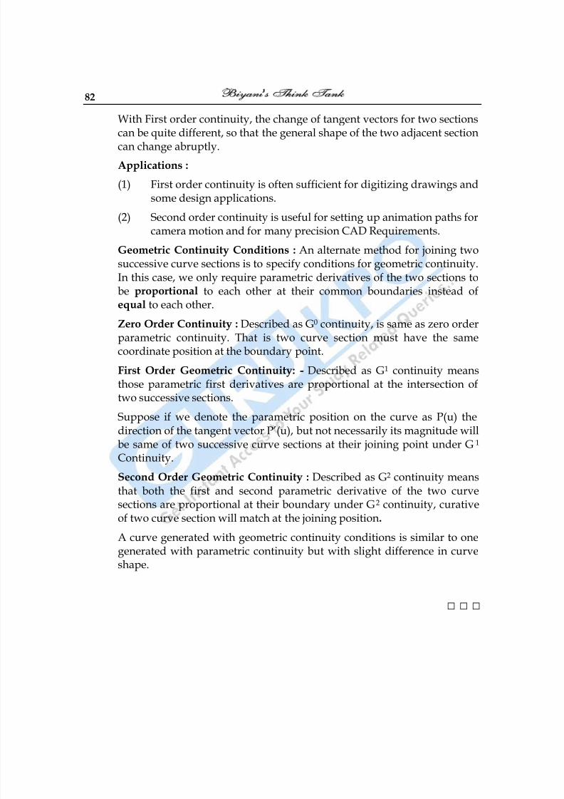
8/10/2019 Computer Graphics & Image Processing
http://slidepdf.com/reader/full/computer-graphics-image-processing 82/117
82
With First order continuity, the change of tangent vectors for two sectionscan be quite different, so that the general shape of the two adjacent sectioncan change abruptly.
Applications :
(1) First order continuity is often sufficient for digitizing drawings andsome design applications.
(2) Second order continuity is useful for setting up animation paths forcamera motion and for many precision CAD Requirements.
Geometric Continuity Conditions : An alternate method for joining twosuccessive curve sections is to specify conditions for geometric continuity.
In this case, we only require parametric derivatives of the two sections tobe proportional to each other at their common boundaries instead ofequal to each other.
Zero Order Continuity : Described as G0 continuity, is same as zero orderparametric continuity. That is two curve section must have the samecoordinate position at the boundary point.
First Order Geometric Continuity: - Described as G1 continuity meansthose parametric first derivatives are proportional at the intersection oftwo successive sections.
Suppose if we denote the parametric position on the curve as P(u) thedirection of the tangent vector P‘(u), but not necessarily its magnitude willbe same of two successive curve sections at their joining point under G 1 Continuity.
Second Order Geometric Continuity : Described as G2 continuity meansthat both the first and second parametric derivative of the two curvesections are proportional at their boundary under G2 continuity, curativeof two curve section will match at the joining position.
A curve generated with geometric continuity conditions is similar to onegenerated with parametric continuity but with slight difference in curveshape.
□ □ □
8/10/2019 Computer Graphics & Image Processing
http://slidepdf.com/reader/full/computer-graphics-image-processing 83/117
Computer Graphics 83
Chapter-7
Image Processing
Q.1 What is Image Processing? What are the operations of ImageProcessing?
Ans.: Image Processing is any form of signal, processing for which Input is anImage such as photographs or frames of video, the output of Imageprocessing can be either an Image or a set of characteristics or parametersrelated to the Image. Most Image processing techniques in values treatingthe image as 2–d signal and applying standard signal processingtechnique to it. Image processing usually refers to digital Imageprocessing but optical and analog image Processing are also possible.
Operations of Image Processing :
(1) Geometric Transformation (Such as enlargement, reduction androtation)
(2) Color Correction (Such as brightness and contrast adjustmentquantization or conversion of different color)
(3) Digital compositing or optical compositing (combination of two ormore Images)
(4) Interpolation and recovery of full image from a draw imageformat.
(5) Image editing
(6) Image registration
(7) Image stabilization
8/10/2019 Computer Graphics & Image Processing
http://slidepdf.com/reader/full/computer-graphics-image-processing 84/117
84
(8) Image segmentation
(9)
Extending dynamic range by combining differently exposedImages.
Q.2 What are the Applications of Image Processing?
Ans.: The applications of Image Processing are :
(1) Computer vision : This is a science and technique of machine thatcan see computer vision is concern with the theory for buildingartificial system that obtains information form Images.
This include system for :(i) Controlling Process (e.g. : Industrial Robot)
(ii) Detecting Events (for like Counting People)
(iii) Organizing Information
(iv) Modeling Objects or Environment (Medical Image Analyses)
(v) Interaction (as the Input to a Device for Computer HumanInteraction)
(2) Face Detection : This Computer technology that determines the
location and sizes of human faces in arbitrary digital Images. Itdetects facial features and ignores everything else like treesbuildings.
(3) Feature Detection : This refers to methods that air at comforting,abstracting of image Information and making decision at everyImage point whether an image feature of a given type at that pointor not.
(4) Land Departure Warning System : This mechanism is designed towarn a driver when vehicle begins to move out of its lane.
(5)
Medical Image Processing : This refers to techniques and processused to create Images of human body for clinical purposes likeentropy radiology.
(6) Microscope Image Processing : This is the broad term that coversto use the digital image processing technique to process analyze
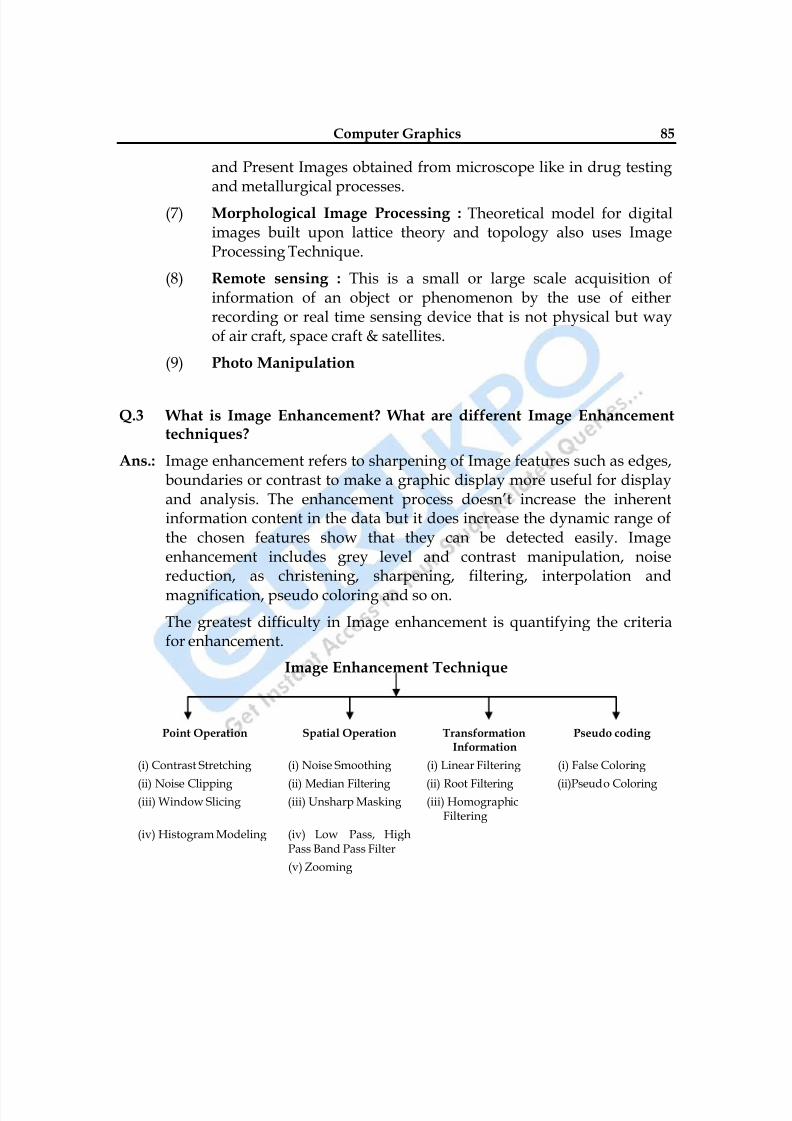
8/10/2019 Computer Graphics & Image Processing
http://slidepdf.com/reader/full/computer-graphics-image-processing 85/117
Computer Graphics 85
and Present Images obtained from microscope like in drug testingand metallurgical processes.
(7) Morphological Image Processing : Theoretical model for digitalimages built upon lattice theory and topology also uses ImageProcessing Technique.
(8) Remote sensing : This is a small or large scale acquisition ofinformation of an object or phenomenon by the use of eitherrecording or real time sensing device that is not physical but wayof air craft, space craft & satellites.
(9) Photo Manipulation
Q.3 What is Image Enhancement? What are different Image Enhancementtechniques?
Ans.: Image enhancement refers to sharpening of Image features such as edges,boundaries or contrast to make a graphic display more useful for displayand analysis. The enhancement process doesn‘t increase the inherentinformation content in the data but it does increase the dynamic range ofthe chosen features show that they can be detected easily. Imageenhancement includes grey level and contrast manipulation, noisereduction, as christening, sharpening, filtering, interpolation and
magnification, pseudo coloring and so on.
The greatest difficulty in Image enhancement is quantifying the criteriafor enhancement.
Image Enhancement Technique
Point Operation Spatial Operation TransformationInformation
Pseudo coding
(i) Contrast Stretching (i) Noise Smoothing (i) Linear Filtering (i) False Coloring
(ii) Noise Clipping (ii) Median Filtering (ii) Root Filtering (ii)Pseudo Coloring(iii) Window Slicing (iii) Unsharp Masking (iii) Homographic
Filtering
(iv) Histogram Modeling (iv) Low Pass, HighPass Band Pass Filter
(v) Zooming
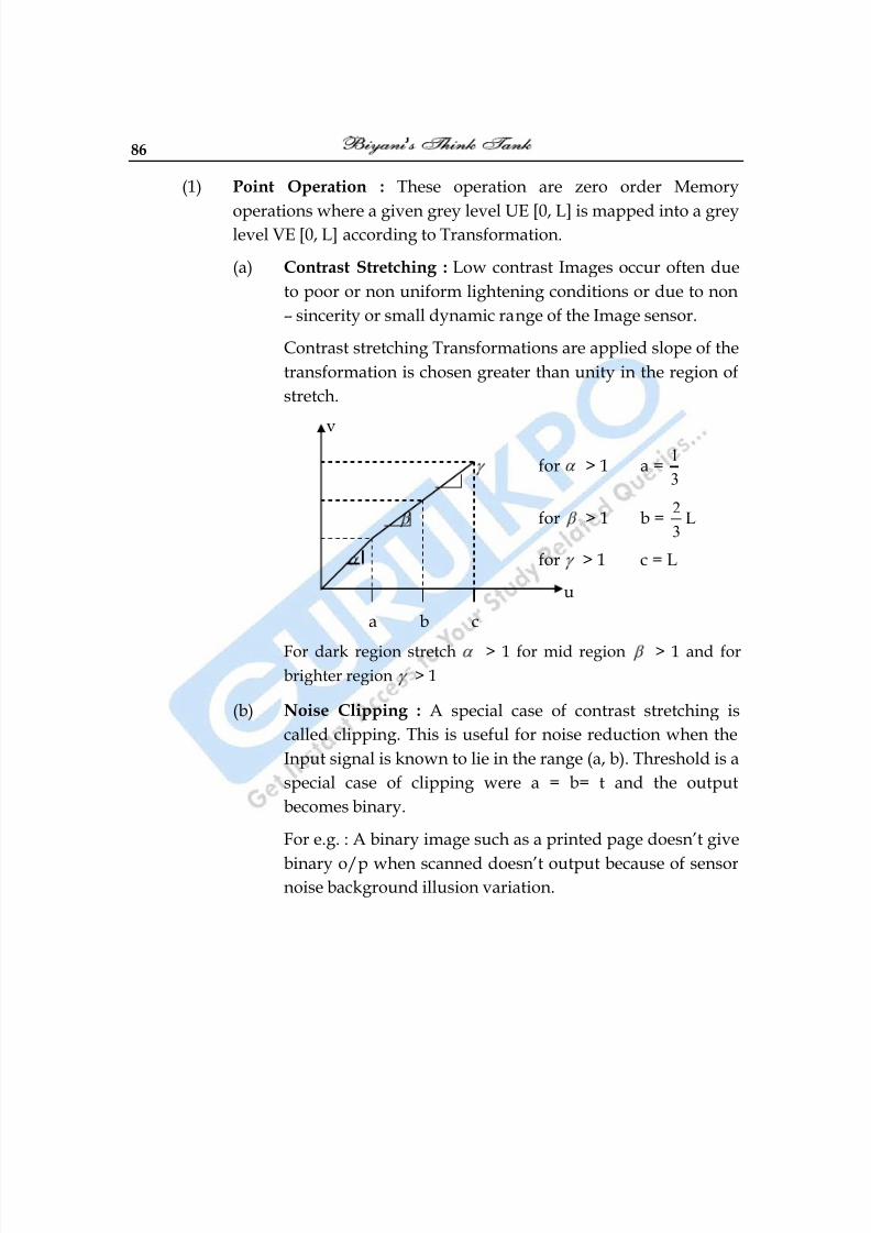
8/10/2019 Computer Graphics & Image Processing
http://slidepdf.com/reader/full/computer-graphics-image-processing 86/117
86
(1) Point Operation : These operation are zero order Memory
operations where a given grey level UE [0, L] is mapped into a greylevel VE [0, L] according to Transformation.
(a) Contrast Stretching : Low contrast Images occur often due
to poor or non uniform lightening conditions or due to non
– sincerity or small dynamic range of the Image sensor.
Contrast stretching Transformations are applied slope of the
transformation is chosen greater than unity in the region of
stretch.
v
for > 1 a =1
3
for > 1 b =2
3L
for > 1 c = L
u
a b c
For dark region stretch > 1 for mid region > 1 and for
brighter region > 1
(b) Noise Clipping : A special case of contrast stretching is
called clipping. This is useful for noise reduction when the
Input signal is known to lie in the range (a, b). Threshold is a
special case of clipping were a = b= t and the output
becomes binary.
For e.g. : A binary image such as a printed page doesn‘t give
binary o/p when scanned doesn‘t output because of sensornoise background illusion variation.
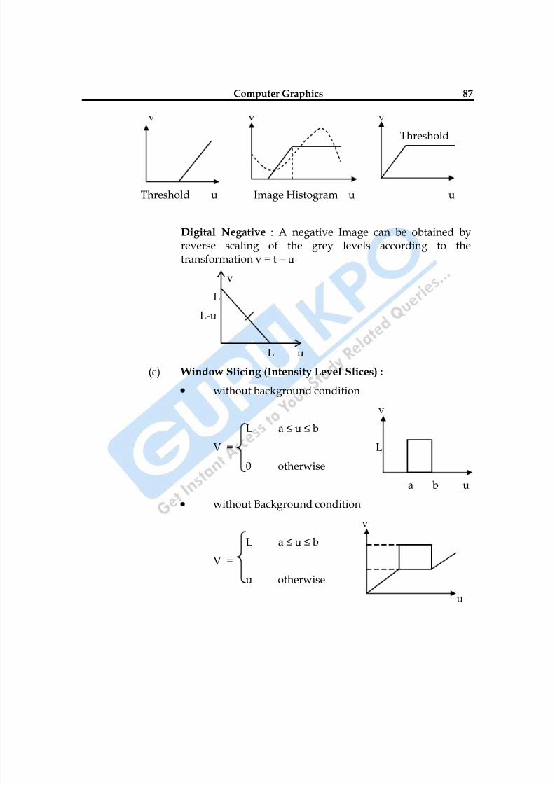
8/10/2019 Computer Graphics & Image Processing
http://slidepdf.com/reader/full/computer-graphics-image-processing 87/117
Computer Graphics 87
v v v
Threshold
Threshold u Image Histogram u u
Digital Negative : A negative Image can be obtained byreverse scaling of the grey levels according to thetransformation v = t – u
v
L
L-u
L u
(c) Window Slicing (Intensity Level Slices) :
without background condition
vL a ≤ u ≤ b
V = L
0 otherwise
a b u
without Background condition
v
L a ≤ u ≤ b
V =
u otherwise
u
8/10/2019 Computer Graphics & Image Processing
http://slidepdf.com/reader/full/computer-graphics-image-processing 88/117
88
These transformation permit segmentation of certain greylevel regions from the rest of the image. This technique isuseful when different features of an image are contained indifferent grey levels.
Bit extraction (It is a minor part of point operation) :Suppose each image pixel is uniformly quantized to b bits. Itis desired to extract the nth most significant bit and display itthen apply the transformation. This transformation is usefulin determine the no of visually significant bit in an Image.
(d) Histogram Modeling : The histogram of an Imagerepresents the relative frequency of occurrence of the
various grey levels in the Image histogram modelingTechnique modify an image so that its histogram has adesired shape. This is useful in stretching the low contrastlevel of Images with narrow histogram. Histogrammodeling has been found to be a powerful technique forimage enhancement.
(i) Histogram Equalization : In this goal is to obtainuniform histogram for the out put Image.
(ii) Histogram Modification (measures frequency
basically) : A generalization of procedure is taken theoutput grey level v is first transformed non linearlyby F(u) and the output is uniformly quantized. Thehistogram is equalization function.
u
f(u) = ∑ Pu (xi,)xi=0
Pu is the probability at a point.
(iii) Histogram Specification : Suppose the randomvariable is greater then Zero with probability density
Pu(u) is to be transform to v ≥ 0 such that it has aspecified probability density Pv(v).
(2) Spatial Operations : Many image enhancement techniques arebased on special operation performed on local neighborhood of
8/10/2019 Computer Graphics & Image Processing
http://slidepdf.com/reader/full/computer-graphics-image-processing 89/117
Computer Graphics 89
input pixels often the image is convolved with the finite responsefilter called spatial Mask.
(a) Noise Smoothening : Here each pixel is replaced by aweighted average of its neighborhood pixel.
v(m, n) = ∑ a(k, l) y(m-k, n-l) (k, l) w
y (m, n) & v (m, n) are input & out put image respectively.
a (k, l) are filter weight.
w = chosen window
Spatial averaging is used for noise smoothening low pass
filtering & sub sampling of Images.The observed Image is given as
y (m, n) = u (m, n) + n (m, n)
denotes noise ratio which has mean value 0.
Directional Smoothening : To protect the edge fromblurring while smooth using a directional averaging filtercan be useful v (m, n, o).
(b) Median Filtering : Here the input pixel is obtained by themedian of the pixel contained in the video around the pixel.
V(m, n) = median {y(m-k, n-l), (k, l) w}
Where w is suitable window.
The Algorithm of median filtering requires arranging thepixel values in the window in increasing & decreasing order& picking the middle value. Generally the window size ischosen so that nw is added. If nw is even then. The median istaken as the average of two values in the meddle.
The median filter has the following properties :
(i)
It is the non linear filter thus for 2-sequences x(m) &y(m) median {x(m) + y(m)} ≠ median {x(m)} + median{y(m)}
(ii) It is useful for removing isolated line of pixels whilepreserving spatial resolution.
8/10/2019 Computer Graphics & Image Processing
http://slidepdf.com/reader/full/computer-graphics-image-processing 90/117
90
(iii) Its performance is poor when the number of noisepixels in the window is greater than or ½ the numberof pixels in the window.
(c) Un sharp Masking Technique : This is used commonly inthe printing industry for cry penning the edges
V (m, n) = u (m, n) + λ g (m, n)
Where λ > 0 & g (m, n) is suitable defined gradient at (m, n)a commonly used gradient fn is the discrete lap lace formula.
(d) Low Pass, High Pass Band Pass Filter : Earlier it wasmentioned spatial avenging operation is a low Pass filter.
hHP(m, n) =LP
m,n – h m,n
hHP denotes high pass filter hLP denotes low Pass filter such a filtercan be implemented by simply subtracting the low Pass filteroutput form its Input. Low Pass filter are useful for Noisesmoothening & interpolation. High Pass filter are useful inextracting edges & in sharpening Images Band pass filters areuseful in enhancement of edges & other high Pass imagecharacteristics in presence of noise.
□ □ □
8/10/2019 Computer Graphics & Image Processing
http://slidepdf.com/reader/full/computer-graphics-image-processing 91/117
Computer Graphics 91
Chapter-8
Multimedia
Q.1 What do you mean by Multimedia? What are its applications?
Ans.: From the word multimedia system we device that it is any system whichsupports more than a single kind of media.
We understand multimedia in a qualitative rather than quantitative way.
A multimedia system is characterized by computer controlled, integratedproduction, manipulation, presentation storage and communication ofindependent Information which is encoded at least through a continuous
(time dependent) and a discrete (time independent) medium.Multimedia is very often used as an attribute of many systems,components, products, ideas etc without satisfying the above presentedcharacters tics.
Multimedia means from the user‘s perspective, that computer informationcan be represented through audio or video, in addition to text, image,graphics and animation.
Applications of Multimedia :
(1) Telecommunication : It began primarily with the Telephone. Then
Telephone Networks changed into digital Networks, which aresimilar to computer Networks.
(2) Consumer Electronics : This contributed massively to thereduction of the price of video support in computers.
8/10/2019 Computer Graphics & Image Processing
http://slidepdf.com/reader/full/computer-graphics-image-processing 92/117
92
(3) Recoding Studios and TV Producers : They are pioneers indealing with professional audio and video equipment. To dayprofessional systems are available for the digital cutting of TVmovies.
(4) Publishing Houses : They offer their publication in electronicform.
(5) Research Centers
Q.2 Write short notes on -
(i) Tweaking
(ii) Morphing a Motion
(iii) Scanners
(ii) Digital Cameras
(iii) Frame Grabbers
Ans.: Tweaking : Tweaking refers to fine tuning or adjusting a complex systemusually an electronic device. Tweaks are any small modifications intendedto improve a system.
(a) Hardware : Hardware tweaking is a process of modifying certain
parts of Hardware such as changing the cables or chords.
(b) Computer Hardware : Computer Hardware tweaking include
changing voltage & clock rates of processing units modifying RAM
unit Timing.
(c) Software : Software tweaking is a process of improving the
performance of an application or quality of its O/P.
Morphing : Morphing is a special effect in motion pictures & animations
that changes one Image into another through seamless transition e.g.
Photoshop Program.(a) Early Morphing Technique : In EMT a morph would be obtained
by crossing – fading from motion picture of one actor or object to
another.
8/10/2019 Computer Graphics & Image Processing
http://slidepdf.com/reader/full/computer-graphics-image-processing 93/117
Computer Graphics 93
(b) Later Morphing Technique : In cross fading of different parts of animage was done instead of transposition the entire Image at once.
(c) Modern Morphing : Here distortion of Image takes place whichwould led to distort the first face to have the shape of second faceat the same time that it faded two faces. E.g. Movie Terminators -2.
Scanners : Scanner is a device that optically scan Images, printed text,handwriting or an object and convent it into digital Images.
Types :
(1) Drum Scanner : Drum scanner capture image information withphoto multiplier tubes (PMT), rather than charge coupled devices
(CCD). It uses red, blue, green beams. The drum scanner gets itsname from the glass drum on which the original artwork ismounted for scanning.
(2) Flatbed : It is usually composed of glass pane, under which there isbright light. Which illuminated the Pane & moving optical arrayImages to be scanned are placed faced down on the glass. Anopaque cover is lowered own it to exclude outside light.
(3) Hand : Hand scanners are manual devices that are dragged acrossthe surface of the Image to be scanned.
Scanners basically meads RGB data from the array.Frame Gabbers : It is an electronic device that captures individual digitalstill frames from an analog video signal or a digital video stream. It isusually employed as a component of a computer version system, in whichvideo frames are captured in digital form & then displayed, stored ortransmitted in raw or compressed digital form.
Early frame buffer had only memory of storing a single digitized videoframe. Modern frame grabbers are able to store multiple frames andcompress the frame in real time using JPEG.
Types of Frame Grabbers :
(a) Analog Frame Grabbers : Which accept & process analog videosignals.
(b) Digital Frame Grabbers : Which accepts & process digital videostreams.
8/10/2019 Computer Graphics & Image Processing
http://slidepdf.com/reader/full/computer-graphics-image-processing 94/117
94
Application :
(1)
Manufacturing : Pick & Place machines are often used to mountelectronic components on circuit boards during circuit boardassemble process. Such machines use one or more cameras tomonitor the robotics that places the components. Each camera ispaired with a frame grabber that digitizes analog video. Thusconverting the video to a form that can be processed by machinesoftware.
(2) Network Security : Frame Grabbers can be used in securityapplication. For eg-when a potential branch of security is detected.A frame grabber captures an image or a sequence of Images & then
images are transmitted across digital N/W where they arerecorded & viewed by security Personal.
Digital Cameras : Here the pictures are taken & stored in digital form inthe Pixels.
Q.3 Write sort notes on JPEG Compression? Explain.
(i) Loss less & loosy compression in JPEG.
(ii) Compression during audio capture in stereo mode.
Ans.: ISO (International Standard Organization) has been working on thestandardized of compression and decompression for still Image.
In 1992 JPEG became an ISO International standard. JPEG is applied tocolor and gray scaled still Images.
A Fast coding and decoding of still Images is also used for videosequences known as Motion JPEG. JPEG fulfils the followingRequirement:
(1) JPEG implementation should be independent of Image size.
(2) JPEG implementation should be applicable to any Image.
(3) Color representation should be independent.
(4) Image content should be of any complexity.
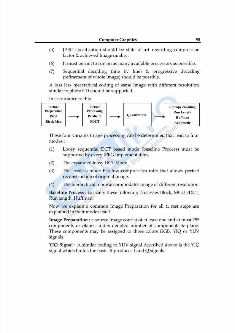
8/10/2019 Computer Graphics & Image Processing
http://slidepdf.com/reader/full/computer-graphics-image-processing 95/117
Computer Graphics 95
(5) JPEG specification should be state of art regarding compressionfactor & achieved Image quality.
(6) It must permit to run on as many available processors as possible.
(7) Sequential decoding (line by line) & progressive decoding(refinement of whole Image) should be possible.
A loss less hierarchical coding of same Image with different resolutionsimilar to photo CD should be supported.
In accordance to this
These four variants Image processing cab be determined that lead to fourmodes :
(1) Loosy sequential DCT based mode (baseline Process) must besupported by every JPEG Implementation.
(2) The expanded loosy DCT Mode.
(3) The lossless mode has low compression ratio that allows perfect
reconstruction of original Image.
(4) The hierarchical mode accommodates image of different resolution.
Baseline Process : basically these following Processes Block, MCU FDCT,Run length, Huffman.
Now we explain a common Image Preparation for all & rest steps areexplained in their modes itself.
Image Preparation : a source Image consist of at least one and at most 255components or planes. Index denoted number of components & plane.
These components may be assigned to three colors GGB, YIQ or YUVsignals.
YIQ Signal : A similar coding to YUV signal described above is the YIQsignal which builds the basis. It produces I and Q signals.
Picture
Preparation
PixelBlock Mcu
Picture
Processing
PredictorFDCT
Quantization
Entropy encoding
Run Length
Huffman
Arithmetic
8/10/2019 Computer Graphics & Image Processing
http://slidepdf.com/reader/full/computer-graphics-image-processing 96/117
96
RGB Signal : This signals consists of separate signals for red, green &blue colors. Other colors are coded as a result of combination of thesecolors like R+G+B = 1 which result into white colors.
YUV Signal : As human perception is more sensitive to brightness thanany chrominance information. In this instead of separating colors weseparate brightness information with color inf (chrominance U & V).
(1) Loosy Sequential DCT Based Mode :
Image Processing : after Image preparation, the uncompressedImage samples are grouped into data units of 8 x 8 pixels & passedto the encoder, the order of these is defined by Mcu
First step is transformation is performed by DCT transformation.These data units are defined by Syx where x & y are in the rangefrom 0 to 7.
This transformation is performed 64 – times per data unit so theresult is 64 coefficient of Syx. DCT is similar is DFT. It maps thevalue from frequency to the domain.
Coefficient : S00 – lowest frequency in both dimensions known asDC coefficient which determine fundamental color of data units of64 pixels.
DC – coefficient is DCT for which the frequency is Zero in bothdimensions. For AC coefficient frequency is one or both
dimensions is Non-Zero.
S70 – represents highest frequency that occurs in horizontal
direction.
S07 – represents highest frequency that occurs in vertical direction.
S77 – represents highest frequency appearing equally in both
directions apply the formula for calculation of Syx
Quantization : In this step quantization of all DCT coefficients isperformed. For this step JPEG provides a table with 64 entries.
Each entry will be used for quantization of 1 of 64 DCT coefficients.
There by each of 64 coefficients are adjusted separately.
8/10/2019 Computer Graphics & Image Processing
http://slidepdf.com/reader/full/computer-graphics-image-processing 97/117
Computer Graphics 97
Preparation of DCT DC – Coefficient for entropy encoding,includes the calculation of the difference between neighboringvalues.
Dc i-1 Dc i
DIF = Dc i - Dc i-1
Each table entry is a 8 – bit integer value. Quantization &dehumanization must use the same table.
Entropy Encoding : During the initial step of entropy encoding, thequantized DC Coefficient are treated separately from AC – Coefficient.
(a) DC Coefficient determines the basic color of the date units.Between adjacent data units color difference is very small.
(b) AC Coefficient using Zig Zag sequences illustrate thatCoefficient with lower frequency (typically with highervalues) are encoded first, followed by higher frequency.
JPEG specifies Huffman & arithmetic encoding as entropy
encoding methods.For lossy sequential DCT Based mode, discussed in this sectiononly Huffman encoding is allowed.
Disadvantage of this is that it must provide tables but JPEG doesnot predefine any of them.
But this provides different Huffman tables for AC & DCCoefficients.
In sequential encoding, the whole Image is coded & decoded in asingle run. The Picture is presented from top to bottom.
(2) Ex Pended Lossy DCT – Based Mode : Image processing in thismode differs from the previously described mode in terms ofnumber of bits per sample. Specifically a sample prevision of 12bits per sample in addition to 8 bits per samples can be used.
Blocki-1 Blocki
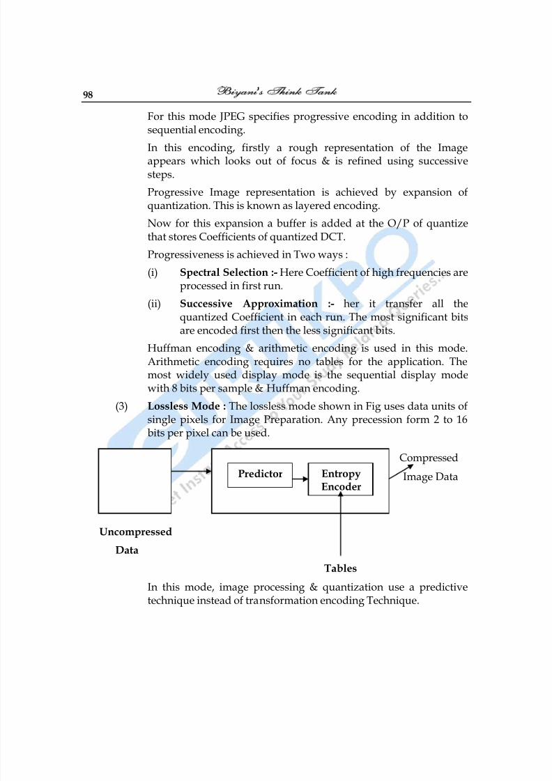
8/10/2019 Computer Graphics & Image Processing
http://slidepdf.com/reader/full/computer-graphics-image-processing 98/117
98
For this mode JPEG specifies progressive encoding in addition tosequential encoding.
In this encoding, firstly a rough representation of the Imageappears which looks out of focus & is refined using successivesteps.
Progressive Image representation is achieved by expansion ofquantization. This is known as layered encoding.
Now for this expansion a buffer is added at the O/P of quantizethat stores Coefficients of quantized DCT.
Progressiveness is achieved in Two ways :
(i)
Spectral Selection :- Here Coefficient of high frequencies areprocessed in first run.
(ii) Successive Approximation :- her it transfer all thequantized Coefficient in each run. The most significant bitsare encoded first then the less significant bits.
Huffman encoding & arithmetic encoding is used in this mode.Arithmetic encoding requires no tables for the application. Themost widely used display mode is the sequential display modewith 8 bits per sample & Huffman encoding.
(3) Lossless Mode : The lossless mode shown in Fig uses data units ofsingle pixels for Image Preparation. Any precession form 2 to 16bits per pixel can be used.
Compressed
Image Data
Uncompressed
Data
Tables
In this mode, image processing & quantization use a predictivetechnique instead of transformation encoding Technique.
Predictor EntropyEncoder
8/10/2019 Computer Graphics & Image Processing
http://slidepdf.com/reader/full/computer-graphics-image-processing 99/117
Computer Graphics 99
For each pixel x one of eight possible predictors is selected. Goodpossible value of x is selected from adjacent samples A, B & C.Now Number of chosen Predictor, as well as difference ofprediction of actual value is passed to subsequent entropyencoding. Either Huffman or arithmetic encoding is used.
(4) Hierarchical Mode : This uses either the lossy DCT based Algo oralternatively the lossless.
Compression Technique : Main feature of this mode is encoding ofan image at different resolution i. e. the encoded date containimages at several resolutions. The prepared Image Is initiallysampled at lower resolution (reduced by the factor 2n).
Disadvantage :
Requires more storage capacity.
Advantage : the compressed Image is immediately available atdifferent resolutions. Application working with lower resolutiondoes not have to decode the whole Image & subsequently applyImage processing Algo to reduce the resolution.
It takes less CPU time to display an image with full resolution thento process a scaled down Image & display it with reduced numberof pixels.
Q.4 Write shout notes on MPEG?
Ans.: MPEG standard was developed by ISO to cover motion video as well asaudio coding.
In 1993 MPEG was accepted as the International standard (IS) MPEGstandard considers functionalities of other standards.
(1) JPEG : Since JPEG is regarded as a sequence of still Images & JPEGstandard developed was ahead of MPEG. MPEG uses JPEGstandard.
(2)
H.261 : since this is a video coding standard it was used in MPEG.
MPEG is suitable for symmetric as well as Asymmetric Compression.Asymmetric Compression requires more efforts for coding than fordecoding.
8/10/2019 Computer Graphics & Image Processing
http://slidepdf.com/reader/full/computer-graphics-image-processing 100/117
100
Compression is carried out once where as decompression is performedmany times.
Video Encoding : First Fig. (basic one) defines the format o fan Image.Each image consists of three components (YUV formats).
MPEG data stream includes more information than a data streamcompressed according to the JPEG standard.
MPEG provides 14 different image aspect ratio per pixel.
MPEG distinguishes four types of image coding for processing. Thereason behind this are the contradictory demands for efficient codingscheme & fast random access.
The types of frames are :_(a) I – Frame (Intra coded Images) : are self contained i. e coded
without any reference to other Images. An I – frame is treated asstill Image MPEG make use of JPEG for I – frames. Thecompression rate of I – frames is the lowest within MPEG I – Frames are points for Random access in MPEG stream.
I frame uses 8 x 8 blocks defined written a macro block MPEGdistinguishes 2 – macro blocks – Ist type includes only encodeddata second covers a parameter used for scaling.
(b) P – Frame (Predictive – Coded frames) : required information ofthe previous I – frame or all previous P – frames for encoding &decoding. Like I frames, P – frames consist of I – frame macroblocks & six – predictive macro blocks. A P – frame can containmacro – blocks, as well as the motion vector.
(c) B – Frame (Bi – directionally predictive–coded frames) : requiresinformation of previous & following I or P – frame for encoding &decoding. B – Frame is defined as the difference of a prediction ofthe past Image & the flowing P or I – frame B – frames can never bedirectly accessed in a random fashion.
For prediction of B – frames the pervious as well as the following Por I frames are taken into Account.
(d) D – Frames (DC – Coded frames) : are intra frame encoded. Theycan be used for fast forward and fast rewind modes. The DCparameters are DCT coded and AC – Coefficient are neglected.
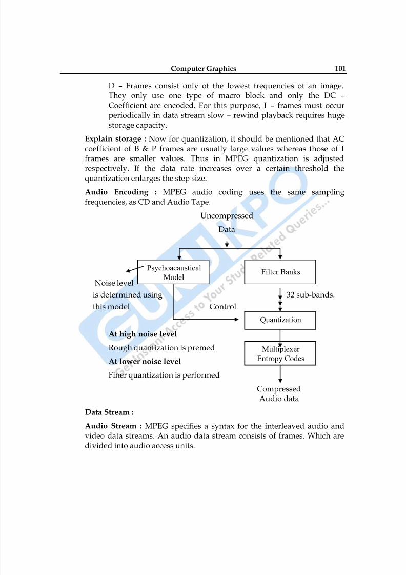
8/10/2019 Computer Graphics & Image Processing
http://slidepdf.com/reader/full/computer-graphics-image-processing 101/117
Computer Graphics 101
D – Frames consist only of the lowest frequencies of an image.They only use one type of macro block and only the DC – Coefficient are encoded. For this purpose, I – frames must occurperiodically in data stream slow – rewind playback requires hugestorage capacity.
Explain storage : Now for quantization, it should be mentioned that ACcoefficient of B & P frames are usually large values whereas those of Iframes are smaller values. Thus in MPEG quantization is adjustedrespectively. If the data rate increases over a certain threshold thequantization enlarges the step size.
Audio Encoding : MPEG audio coding uses the same sampling
frequencies, as CD and Audio Tape.
Uncompressed
Data
Noise level
is determined using 32 sub-bands.
this model Control
At high noise level
Rough quantization is premed
At lower noise level
Finer quantization is performed
Compressed
Audio dataData Stream :
Audio Stream : MPEG specifies a syntax for the interleaved audio andvideo data streams. An audio data stream consists of frames. Which aredivided into audio access units.
Psychoacaustical
ModelFilter Banks
Quantization
Multiplexer
Entropy Codes
8/10/2019 Computer Graphics & Image Processing
http://slidepdf.com/reader/full/computer-graphics-image-processing 102/117
102
Each audio access units is composed of slots.
A lowest complexity (Layer 1) a slot consists of 4 – bytes. In other Layer itconsists of one byte.
Video Stream : video data stream comprises of 6 Layers :
(1) At the highest level, the sequence Layer, data buffering is handled,the data stream should have low requirement in terms of storedcapacity. For this reason at the beginning of sequences Layer thereare two entries - constant bit rate of the sequence & storagecapacity that is needed for decoding.
(2) The group of picture layer is next layer. This layer consist of
minimum 1 I – Frame. Which is first frame random access to thisimage is always possible.
At this layer order of images in data stream is maintained firstimage of data stream has to be I frame and for display B – framecan occur before I – frame.
(3) Picture layer contains a whole picture. The temporal reference isdefined by an image number. Data fields are defined in this layer,but decoder is not allowed to use these data fields.
(4) Next is slice layer. Each slice consists of macro blocks that may
vary from one image to next.(5) This is Macro block Layer. It contains fraters of each macro block as
described in above Layer.
(6) Lowest is block Layer.
MPEG standard specifies combination of data streams into a single datastream in system definition. MPEG defined the process of decoding.
□ □ □

8/10/2019 Computer Graphics & Image Processing
http://slidepdf.com/reader/full/computer-graphics-image-processing 103/117
Computer Graphics 103
Multiple Choice Questions
1) The smallest addressable screen element. Is called?
A. Pixel
B. Graph
C. voltage level
D. color information
2) Pixel on the graphics display represents?
A. mathematical point
B. a region which theoretically can contain an infinite number of points
C. voltage values
D. picture
3) The process of determining the appropriate pixels for representing picture or
graphics object is known as?
A.
rasterizationB. animationC. both a and b
D. representation
4) The relationship among the data and objects which are stored in the database
called application database, and referred by the?
A. Application programs
B. application model
C. graphics display
D.
both a and b
5) Selective or part erasing of screen is not possible in?
A. raster scan display

8/10/2019 Computer Graphics & Image Processing
http://slidepdf.com/reader/full/computer-graphics-image-processing 104/117
104
B. vector scan displayC.
DVST
D.
both a and b
6) display processor is also called a?
A. graphics controller
B. display coprocessorC. both a and b
D. out put device for graphics
7) Graphics software acts as a very powerful tool to create?
A.
ImagesB. animated picturesC. both a and b
D. system interface
8) The purpose of display processor is __from the graphics routine task?
A. to free the CPU
B. To free the secondary memoryC. to free the main memory
D. Both a & c
9) random-scan monitors typically offer __color choices?
A. Only a few
B. wide rangeC. just 1 or 2
D. moderate range of
10) RGB system needs __of storage for the frame buffer?
A. 100 megabytes
B.
10 megabytesC. 3 megabytes
D. 2 Gb

8/10/2019 Computer Graphics & Image Processing
http://slidepdf.com/reader/full/computer-graphics-image-processing 105/117
Computer Graphics 105
11) The SRGP package provides the __to wide the variety of display devices?
A.
interface
B.
connectionC. link
D. way
12) Length of shift register in bits is equal to __?
A. one word
B. A single scan lines
C. number of scan lines
D. One bit
13) Display controller is not required for __?
A. display system with only frame buffer
B. Display system with display controller
C. both a and b
D. display system with color
14) The basic principle of Bresenham`s line algorithm is__?
A. to select the optimum raster locations to represent a straight line
B. to select either Δx or Δy, whichever is larger, is chosen as one raster unit
C.
we find on which side of the line the midpoint liesD. both a and b
15) The midpoint circle drawing algorithm also uses the __of the circle to generate?
A. two-way symmetry
B. four-way symmetryC. eight-way symmetry
D. both a & b
16) a polygon in which the line segment joining any 2 points within the polygon lies
completely inside the polygon is called__?
A. convex polygon

8/10/2019 Computer Graphics & Image Processing
http://slidepdf.com/reader/full/computer-graphics-image-processing 106/117
106
B. concave polygonC.
both a and b
D.
both a and b
17) A polygon in which the line segment joining any 2 points within the polygon may
not lie completely inside the polygon is called __?
A. convex polygonB. concave polygon
C. both a and b
D. Hexagon
18) Rectangular patterns are sometimes referred as__?A. tiling patternsB. Filling patterns
C. coloring patterns
D. both a and b
19) Replicating pixels is one of the methods of__?
A. Thick primitives
B. Thin primitives
C.
stylish primitivesD. both a and b
20) Line produced by moving pen is __ at the end points than the line produced by
the pixel replication?
A. thin
B. straightC. thicker
D. both a and b
21) The process of selecting and viewing the picture with different views is called__?A. Windowing
B. clipping
C. projecting
D. both a and b

8/10/2019 Computer Graphics & Image Processing
http://slidepdf.com/reader/full/computer-graphics-image-processing 107/117
Computer Graphics 107
22) The process which divides each element of the picture into its visible and
invisible portions, allowing the invisible portion to be discarded is called__?
A. clippingB. Windowing
C. both a and b
D. Projecting
23) The region against which an object is to be clipped is called__?
A. clip window or clipping window
B.
Drawing windowC. image windowD. both b and c
24) The region code 0000 represents the__?
A. viewing window
B. left clipping windowC. right clipping window
D. bottom clipping window
25) A method used to test lines for total clipping is equivalent to the__?
A. logical XOR operator
B. logical OR operatorC. logical AND operator
D. both a and b
26) A process of changing the position of an object in a straight line path from one
coordinate location to another is called__?
A.
TranslationB. rotation
C. motion
D. both b and c
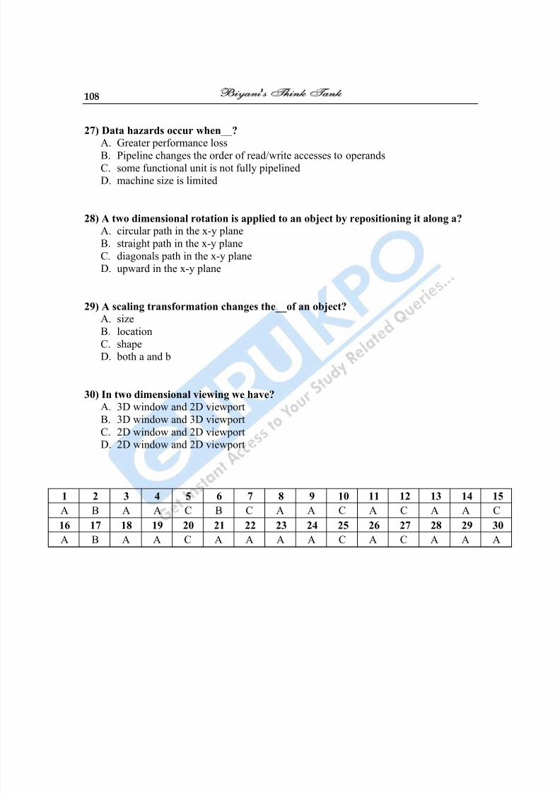
8/10/2019 Computer Graphics & Image Processing
http://slidepdf.com/reader/full/computer-graphics-image-processing 108/117
108
27) Data hazards occur when__?
A.
Greater performance lossB. Pipeline changes the order of read/write accesses to operands
C. some functional unit is not fully pipelinedD. machine size is limited
28) A two dimensional rotation is applied to an object by repositioning it along a?
A. circular path in the x-y plane
B. straight path in the x-y plane
C. diagonals path in the x-y planeD. upward in the x-y plane
29) A scaling transformation changes the__of an object?
A. size
B. location
C. shapeD. both a and b
30) In two dimensional viewing we have?
A. 3D window and 2D viewport
B.
3D window and 3D viewportC. 2D window and 2D viewportD. 2D window and 2D viewport
1 2 3 4 5 6 7 8 9 10 11 12 13 14 15
A B A A C B C A A C A C A A C
16 17 18 19 20 21 22 23 24 25 26 27 28 29 30
A B A A C A A A A C A C A A A

8/10/2019 Computer Graphics & Image Processing
http://slidepdf.com/reader/full/computer-graphics-image-processing 109/117
Computer Graphics 109
Case study1.) Implement the polyline function using the DDA algorithm, given any number (n) of
input points.
2.) How much time is used up scanning across each row of pixels for the duration of
screen refresh on a raster system with a resolution of 1290 by 1024 and a refresh rate of
60 frames per second?
3.) Implement a procedure to perform a one-point perspective projection of an object.
4.) Implement a procedure to perform a one-point perspective projection of an object.

8/10/2019 Computer Graphics & Image Processing
http://slidepdf.com/reader/full/computer-graphics-image-processing 110/117
110
Glossary
2D Graphics
Displayed representation of a scene or an object along two axes of reference: height and width (xand y).
3D Graphics
Displayed representation of a scene or an object that appears to have three axes of reference:height, width, and depth (x, y, and z).
3D Pipeline
The process of 3D graphics can be divided into three-stages: tessellation, geometry, andrendering. In the tessellation stage, a described model of an object is created, and the object isthen converted to a set of polygons. The geometry stage includes transformation, lighting, and
setup. The rendering stage, which is critical for 3D image quality, creates a two dimensionaldisplay from the polygons created in the geometry stage.
Anti-aliasing
Anti-aliasing is sub pixel interpolation, a technique that makes edges appear to have betterresolution.
Bitmap
A Bitmap is a pixel by pixel image.
Blending
Blending is the combining of two or more objects by adding them on a pixel-by-pixel basis.
Depth Cueing
Depth cueing is the lowering of intensity as objects move away from the viewpoint.
8/10/2019 Computer Graphics & Image Processing
http://slidepdf.com/reader/full/computer-graphics-image-processing 111/117
Computer Graphics 111
Dithering
Dithering is a technique for archiving 24-bit quality in 8 or 16-bit frame buffers. Dithering usestwo colors to create the appearance of a third, giving a smooth appearance to an otherwise abrupttransition.
Flat Shading
The flat shading method is also called constant shading. For rendering, it assigns a uniform colorthroughout an entire polygon. This shading results in the lowest quality, an object surface with a
faceted appearance and a visible underlying geometry that looks 'blocky'.
Hidden Surface Removal
Hidden Surface Removal or visible surface determination entails displaying only those surfacesthat are visible to a viewer because objects are a collection of surfaces or solids.
Interpolation
Interpolation is a mathematical way of regenerating missing or needed information. For example,an image needs to be scaled up by a factor of two, from 100 pixels to 200 pixels. The missing
pixels are generated by interpolating between the two pixels that are on either side of the pixel
that needs to be generated. After all of the 'missing' pixels have been interpolated, 200 pixels existwhere only 100 existed before, and the image is twice as big as it used to be.
Lighting
There are many techniques for creating realistic graphical effects to simulate a real-life 3-D objecton a 2-D display. One technique is lighting. Lighting creates a real-world environment by meansof rendering the different grades of darkness and brightness of an object's appearance to make theobject look solid.
Line Buffer
A line buffer is a memory buffer used to hold one line of video. If the horizontal resolution of thescreen is 640 pixels and RGB is used as the color space, the line buffer would have to be 640
locations long by 3 bytes wide. This amounts to one location for each pixel and each color plane.Line buffers are typically used in filtering algorithms.
8/10/2019 Computer Graphics & Image Processing
http://slidepdf.com/reader/full/computer-graphics-image-processing 112/117
112
Projection
The process of reducing three dimensions to two dimensions for display is called Projection. It isthe mapping of the visible part of a three dimensional object onto a two dimension screen.
Rasterization
Translating an image into pixels.
Rendering
The process of creating life-like images on a screen using mathematical models and formulas toadd shading, color, and lamination to a 2D or 3D wireframe.
Transformation
Change of coordinates; a series of mathematical operations that act on output primitives andgeometric attributes to convert them from modeling coordinates to device coordinates.
Z-buffer
A part of off-screen memory that holds the distance from the viewpoint for each pixel, the Z-value. When objects are rendered into a 2D frame buffer, the rendering engine must removehidden surfaces.
Z-buffering
A process of removing hidden surfaces using the depth value stored in the Z-buffer. Before bringing in a new frame, the rendering engine clears the buffer, setting all Z-values to 'infinity'.
When rendering objects, the engine assigns a Z-value to each pixel: the closer the pixel to theviewer, the smaller the Z value. When a new pixel is rendered, its depth is compared with the
stored depth in the Z-buffer. The new pixel is written into the frame buffer only if its depth valueis less than the stored one.
Z-sorting
A process of removing hidden surfaces by sorting polygons in back-to-front order prior torendering. Thus, when the polygons are rendered, the forward-most surfaces are rendered last.
The rendering results are correct unless objects are close to or intersect each other. The advantage

8/10/2019 Computer Graphics & Image Processing
http://slidepdf.com/reader/full/computer-graphics-image-processing 113/117
Computer Graphics 113
is not requiring memory for storing depth values. The disadvantage is the cost in more CPUcycles and limitations when objects penetrate each other.
Filtering
This is a broad word which can mean the removal of coffee grinds from the coffee.
However, within the narrow usage of this book, a filtering operation is the same as a
convolution operation (see "convolution"). Anti-aliasing is usually done by filtering.
flat projection
A method of projecting a 3D scene onto a 2D image such that the resulting object sizes
are not dependent on their position. Flat projection can be useful when a constant scale is
needed throughout an image, such as in some mechanical drawings.
Frame
One complete video image. When interlacing is used, a frame is composed of two fields,
each containing only half the scan lines.
GIF
A file format for storing images. GIF stands for Graphics Interchange format, and isowned by Compuserve, Inc.
key frame
A selected frame of an animation at which all the scene state is defined. In the key frame
animation method, the scene state at key frames is interpolated to create the scene state at
the in-between frames.
key frame animation
An animation control method that works by specifying the complete scene state at
selected, or key, frames. The scene state for the remaining frames is interpolated from the
state at the key frames.
Raster Scan
8/10/2019 Computer Graphics & Image Processing
http://slidepdf.com/reader/full/computer-graphics-image-processing 114/117
114
The name for the pattern the electron beam sweeps out on a CRT face. The image is
made of closely spaced scan lines, or horizontal sweeps.
Refresh Rate
The rate at which parts of the image on a CRT are re-painted, or refreshed. The horizontal
refresh rate is the rate at which individual scan lines are drawn. The vertical refresh rateis the rate at which fields are drawn in interlaced mode, or whole frames are drawn in
non-interlaced mode.
Refresh Rate, Horizontal
The rate at which scan lines are drawn when the image on a CRT is re-drawn, orrefreshed.
Refresh Rate, Vertical
The rate at which fields are re-drawn on a CRT when in interlaced mode, or the rate atwhich the whole image is re-drawn when in non-interlaced mode.
Scan Line
One line in a raster scan. Also used to mean one horizontal row of pixels.
8/10/2019 Computer Graphics & Image Processing
http://slidepdf.com/reader/full/computer-graphics-image-processing 115/117
Computer Graphics 115
M.Sc.(Information Technology)(SECOND-SEMESTER)EXAMINATION, 2012
(New Scheme)
COMPUTER GRAPHICS AND MULTIMEDIA TECHNOLOGYPAPER: 121
TIME ALLOWED: THREE HOURSMaximum Marks—80
Note:-(1) No supplementary answer-book will be given to any candidate. Hence the
candidates should write the answers precisely in the Main answer-book only.
(2)
All the parts of question should be answered at one place in the answer-book.One complete question should not be answered at different places in the answer –
book.
Attempt FIVE questions in out of nine
All question carry equal marks
1.
(a) What is the need of Graphics? List the different application of
Computer Graphics.
(b) Explain the following (any two)
(i) Tablet
(b) Trackball and Mouse
(iii) Inkjet Printers.
2. (a) What is 2D transformation? Explain different types of transformation.
(b) Magnify the trangle with vertices A (0,0) , B(1,1) and C(5,2) to twice its
size while keeping C(5,2) fixed
3. (a) What do you understand by scan conversion? Explain Bresenham‘s
Line Algorithm.

8/10/2019 Computer Graphics & Image Processing
http://slidepdf.com/reader/full/computer-graphics-image-processing 116/117
116
(b) Write the steps required to plot a line whose slope is between 00 450
using the slope intercept equation or using Bresenham‘s method.
4.(a) What is Choen-Sutherland line clipping algorithm ? Explain….(b) What is hidden surface removal? Discuss one algorithm for displaying
visible surfaces of number of object in the scene.
5. (a) What are the properties of Bezier curve with respect to a set of controlpoints? For the case of 4 control point,derive blending functions andtheir shapes.
(b) What is the B-spline and Bezier curve? Explain the A-buffer basedhidden surface algorithm.
6. (a) Discuss how use of homogeneous coordinates permits us to useefficient computing of geometric transformations in computergraphics.
(b) Find the matric that represent rotation of an object by 300 about theorigin.
7. (a) What is Multimedia ? Explain Simulating Acceleration.(b) Write short notes on the following :
(i) Morphing
(ii) MPEG(iii) MIDI waves files.
8. (a) What do you mean by Image Enhancements?(b) What are the differences between Analog and Digital Video
Image? Explain Images/Screen Resolution.
9. Write short notes on the following (any four) (a) Tweaking:(b) Motion Specification:
(c) Capture and storage of Digital Images;(d) Frames Grabers;(e) Image Processing.
8/10/2019 Computer Graphics & Image Processing
http://slidepdf.com/reader/full/computer-graphics-image-processing 117/117
Computer Graphics 117
Bibliography
1. J. Foley, A. Van Dam, S. Feiner, J. Hughes: Computer Graphics- Principles andPractice, Pearson
2. Hearn and Baker: Computer Graphics, PHI.
3 Computer Graphics by Pradeep K. Bhatia
4 Computer Graphics: Principles & Practice In C Foley
5 Computer graphics: Francis S. Hill
Best sites for computer graphics:-
1. http://www.cgsociety.org/2. http://forums.cgsociety.org/
3. http://www.maacindia.com/
4. http://cg.tutsplus.com/
5.
http://programmedlessons.org/VectorLessons/index.html