computer networking chap3
DESCRIPTION
Computer Networking 4th Chap3TRANSCRIPT

3-1
Chap.3 Transport LayerGoal : study principle of providing comm services to app processes and implementation issues in the Internet protocols, TCP and UDP
ContentsRelationship bw transport and net layers
extending net layer’s delivery service to a delivery service bwtwo app-layer processes, by covering UDP
Principles of reliable data transfer and TCPPrinciples of congestion control and TCP’s congestion control

3-2
Chap.3 Transport LayerIntroduction and Transport-Layer Services
Relationship Between Transport and Network LayersOverview of the Transport Layer in the Internet
Multiplexing and Demultiplexing
Connectionless Transport: UDP
Principle of Reliable Data Transfer
Connection-Oriented Transport: TCP
Principles of Congestion Control
TCP Congestion Control

3-3
Overview of Transport-layerprovide logical comm bw app processes running on diff hosts
transport protocols run in end systems
sending side: converts msgs from app process into transport-layer pkts (segments in Internet term), passes them to net layer
(possibly) break app msgs into small chunks, and add headers
receiving side: processes segments from net layer, making them available to app
more than one transport protocol available to apps
Internet: TCP and UDP
3-4
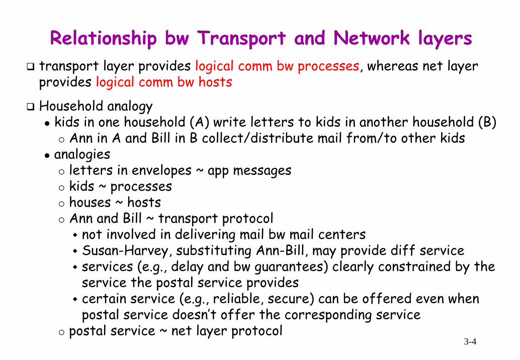
Relationship bw Transport and Network layerstransport layer provides logical comm bw processes, whereas net layer provides logical comm bw hosts
Household analogykids in one household (A) write letters to kids in another household (B)
Ann in A and Bill in B collect/distribute mail from/to other kidsanalogies
letters in envelopes ~ app messageskids ~ processeshouses ~ hostsAnn and Bill ~ transport protocol
not involved in delivering mail bw mail centersSusan-Harvey, substituting Ann-Bill, may provide diff serviceservices (e.g., delay and bw guarantees) clearly constrained by the service the postal service providescertain service (e.g., reliable, secure) can be offered even when postal service doesn’t offer the corresponding service
postal service ~ net layer protocol

3-5
Overview of Transport-layer in the InternetIP (Internet Protocol) provides best-effort delivery service
makes “best-effort” to deliver segments, but no guarantees : no guarantee on orderly delivery, integrity of data in segments
⇒ unreliable service
User Datagram Protocol (UDP) : provides an unreliable connectionless service, no-frills extension of IP service
transport-layer multiplexing and demultiplexing : extend IP’s host-to-host delivery to process-to-process deliveryintegrity checking by including error-detection fields in segment header
Transmission Control Protocol (TCP) : provides a reliable connection-oriented service with several additional services to app
reliable data transfer : correct and in-order delivery by usingflow control and error control (seq #, ack, timers)
connection setupcongestion control

3-6
Chap.3 Transport LayerIntroduction and Transport-Layer Services
Multiplexing and Demultiplexing
Connectionless Transport: UDP
Principle of Reliable Data Transfer
Connection-Oriented Transport: TCP
Principles of Congestion Control
TCP Congestion Control

3-7
Multiplexing and Demultiplexinga process can have one or more sockets; each socket having a unique id
multiplexing at sending host : Ann’s job in household analogygathering data chunks at sources from diff socketsencapsulating each chunk with header info to create segmentspassing segments to net layer
demultiplexing at receiving host : Bill’s job in household analogydelivering data in a seg to the correct socket

3-8
How Demultiplexing Workshost receives IP datagrams
each datagram has src and dst IP addrseach datagram carries a transport-layer seg
each seg has src and dst port #swell-known port #s : reserved for well-known app protocols, ranging 0 ~ 1023 : HTTP(80), FTP(21), SMTP(25) , DNS(53)other #s : can be used for user apps
IP addrs and port #s used to direct seg to appropriate socket

3-9
Connectionless Multiplexing and Demultiplexingcreating UDP socketDatagramSocket mySocket1 = new DatagramSocket();
transport layer automatically assigns a port # to the socket, in the range 1024~65535 not currently used by other UDP ports
DatagramSocket mySocket2 = new DatagramSocket(19157);app assigns a specific port # 19157 to the UDP socket
typically, the port # in the client side is automatically assigned, whereas the server side assigns a specific port #
When a host receives UDP seg, it checks dst port # in the seg and directs the seg to the socket with that port #
UDP socket identified by 2-tuple : (dst IP addr, dst port #)
IP datagrams with diff src IP addrs and/or src port #s are directed to the same socket
src port addr is used as dst port addr in return seg

3-10
TCP socket identified by 4-tuple(src IP addr, src port #, dst IP addr, dst port #)
demultiplexing at receiving host4-tuple used to direct seg to appropriate socketTCP segs with diff src IP addrs or src IP port #s are directed to two diff sockets (except TCP seg carrying conn-establishment request)
server host may support many simultaneous TCP socketseach socket identified by its own 4-tuple
Connection-Oriented Mux/Dumux (1)

3-11
Connection-Oriented Mux/Dumux (2)

3-12
Connection-Oriented Mux/Demux : Threaded ServerToday’s high-performing Web server uses only one process, but creating a new thread with a new conn for each new client conn
connection sockets may be attached to the same process

3-13
Chap.3 Transport LayerIntroduction and Transport-Layer Services
Multiplexing and Demultiplexing
Connectionless Transport: UDPUDP Segment StructureUDP Checksum
Principle of Reliable Data Transfer
Connection-Oriented Transport: TCP
Principles of Congestion Control
TCP Congestion Control

3-14
User Datagram Protocol (UDP) [RFC 768]no-frills, bare bones transport protocol : adds nothing to IP but,
multiplexing/demultiplexing : src and dst port #s(light) error checking
features of UDPunreliable best-effort service : no guarantee on correct delivery
UDP segments may be lost and delivered out of order to appconnectionless : no handshaking bw UDP sender and receiver
Q: Isn’t TCP always preferable to UDP? A: Nosimple, but suitable to certain apps such as real-time apps
stringent to delay, but tolerable to some data lossno conn establishment ⇒ no additional notable delaysimple ⇒ no conn state, including send/receive buffers, congestion-control parameters, seq and ack # parameterssmall pkt header overhead : 8 bytes compared to 20 bytes in TCP

3-15
Popular Internet Apps and Their Protocols

3-16
Controversy on UDPUDP is lack of congestion control and reliable data transfer
when many users starts streaming high-bit rate video, packet overflow at routers, resulting in
high loss rates for UDP packetsdecrease TCP sending rate
⇒ adaptive congestion control, forcing all sources including UDP sources, required in particular streaming multimedia apps
build reliability directly into app (e.g., adds ack/rexmission)many of today’s proprietary streaming apps run over UDP, but builds ack and rexmission into app in order to reduce pkt lossnontrivial, but can avoid xmission-rate constraint imposed by TCP’s congestion control mechanism

3-17
UDP Segment StructureSource port #, dst port # : used for multiplexing/demultiplexing
Length : length of UDP seg including header, in bytes
Checksum : to detect errors (i.e., bits altered) on an end-end basiserror source : noise in the links or while store in a router
some link-layer protocol may not provide error checking
3-18
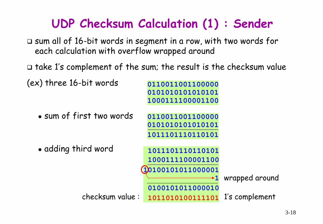
UDP Checksum Calculation (1) : Sendersum all of 16-bit words in segment in a row, with two words for each calculation with overflow wrapped around
take 1’s complement of the sum; the result is the checksum value
(ex) three 16-bit words
sum of first two words
adding third word
011001100110000001010101010101011000111100001100
011001100110000001010101010101011011101110110101
1011101110110101100011110000110010100101011000001
101001010110000101011010100111101
wrapped around
1’s complementchecksum value :
3-19
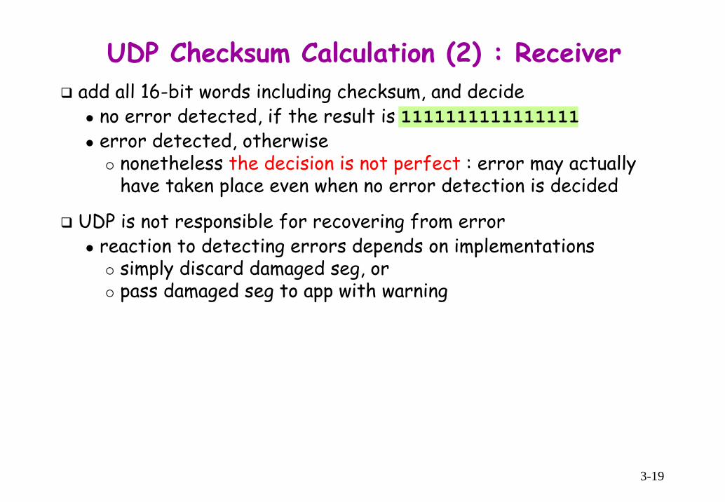
add all 16-bit words including checksum, and decideno error detected, if the result is 1111111111111111error detected, otherwise
nonetheless the decision is not perfect : error may actually have taken place even when no error detection is decided
UDP is not responsible for recovering from errorreaction to detecting errors depends on implementations
simply discard damaged seg, orpass damaged seg to app with warning
UDP Checksum Calculation (2) : Receiver

3-20
Chap.3 Transport LayerIntroduction and Transport-Layer Services
Multiplexing and Demultiplexing
Connectionless Transport: UDP
Principle of Reliable Data TransferBuilding a Reliable Data Transfer ProtocolPipelined Reliable Data Transfer ProtocolGo-Back-N (GBN)Selective Repeat (SR)
Connection-Oriented Transport: TCP
Principles of Congestion Control
TCP Congestion Control

3-21
Reliable Data Transfer : Service Model and Implementationreliable data transfer : no corruption, no loss, and in-order delivery
of central importance to networking : not only at transport layer, but also at link layer and app layer
rdt_send() : called from app
deliver_data() : called by rdtto deliver data to app
udt_send() : called by rdt to sen pkt over unreliable channel rdt_rcv() : called from
channel upon pkt arrival

3-22
Reliable Data Transfer: Implementation Considerationcharacteristics of unreliable channel determines the complexity of reliable data transfer protocol
We willincrementally develop sender and receiver sides of rdt protocol, considering increasingly complex model of underlying channelconsider only unidirectional data transfer for simplicity purpose
but, control packet is sent back and forthuse finite state machines (FSM) to specify sender, receiver
state1
state2
event causing state transitionactions taken on state transition
state: next state uniquely determined by event
dashed arrow : initial state
Λ : no event or no action

3-23
rdt1.0 : Perfectly Reliable ChannelAssumptions of underlying channel
perfectly reliable : no bit errors, no loss of packets
separate FSMs for sender and receiversender sends data into underlying channelreceiver read data from underlying channel
3-24
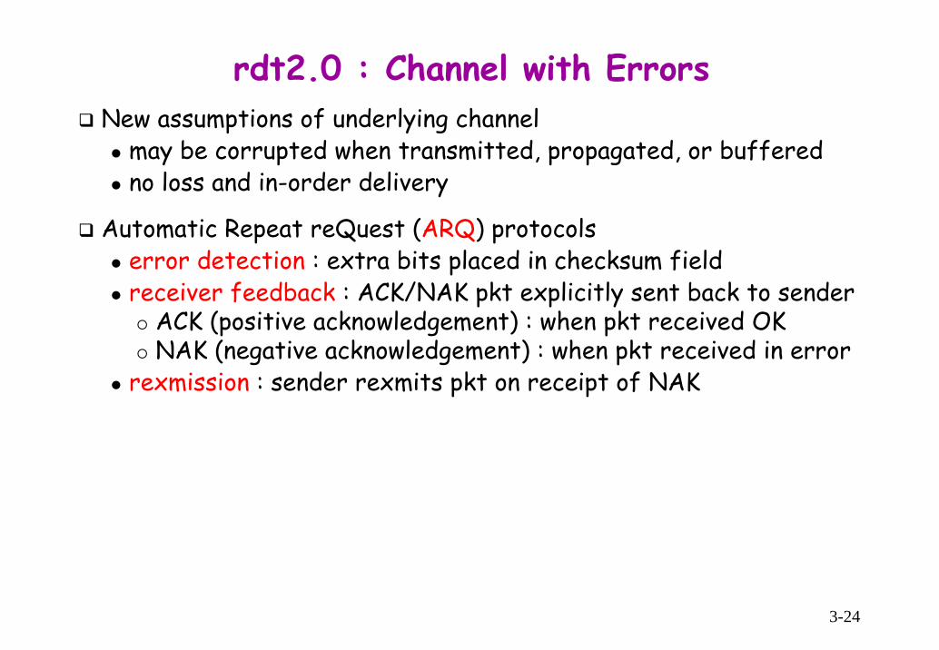
rdt2.0 : Channel with ErrorsNew assumptions of underlying channel
may be corrupted when transmitted, propagated, or bufferedno loss and in-order delivery
Automatic Repeat reQuest (ARQ) protocolserror detection : extra bits placed in checksum fieldreceiver feedback : ACK/NAK pkt explicitly sent back to sender
ACK (positive acknowledgement) : when pkt received OKNAK (negative acknowledgement) : when pkt received in error
rexmission : sender rexmits pkt on receipt of NAK
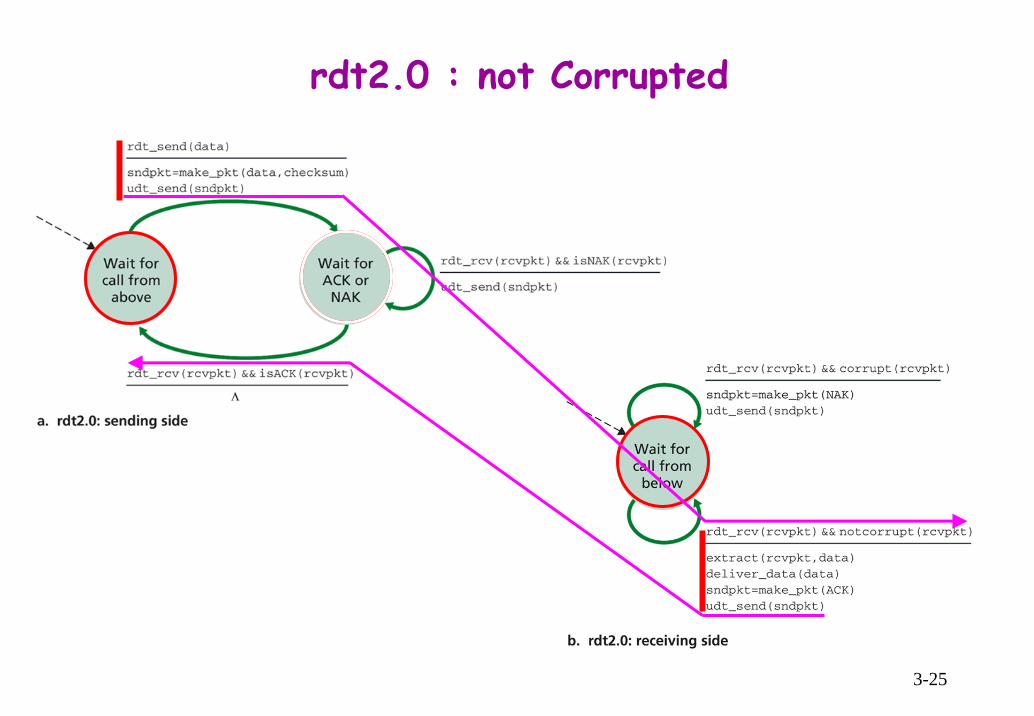
3-25
rdt2.0 : not Corrupted

3-26
rdt2.0 : Corrupted

3-27
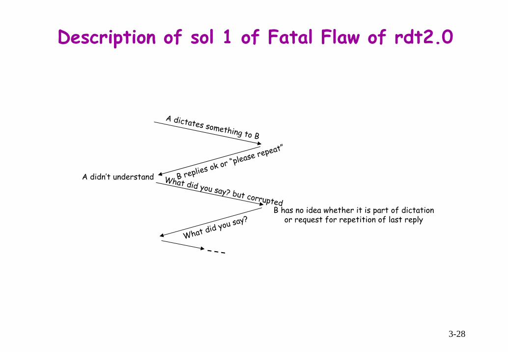
rdt2.0 : Fatal FlawQ: How to recover from errors in ACK or NAK pkts?
minimally, need to add checksum bits to ACK/NAK pktspossible solutions
repeated requests from sender/receiver for a garbled ACK and NAK : hard to find a clue to way outadd enough checksum bits for correction : not applicable for lost pktsimply resend the pkt when receiving a garbled ACK or NAK ⇒incurs possible duplicate at receiver
receiver doesn’t know whether it is a new pkt or a rexmission(i.e., a duplicate pkt)
handling duplicates : add a new field (seq # field) to the packetsender puts a seq # into this field, and receiver discards duplicate pkt1-bit seq # suffice for stop-and-stop protocol
rdt2.0 is stop-and-wait protocol : sender sends one pkt, then waits for receiver response
3-28
Description of sol 1 of Fatal Flaw of rdt2.0
A dictates something to B
B replies ok or “please repeat”
A didn’t understand What did you say? but corruptedB has no idea whether it is part of dictation
or request for repetition of last reply
What did you say?

3-29
rdt2.1 : Employing Seq # - Sender

3-30
rdt2.1 : Employing Seq # - Receiver

3-31
rdt2.1 : Discussionsender
seq # added to pkttwo seq #’s (0,1) will sufficemust check if received ACK/NAK corrupted twice as many states
state must remember whether current pkt has seq # of 0 or 1
receivermust check if received pkt is duplicate
state indicates whether 0 or 1 is expected pkt seq #receiver cannot know if its last ACK/NAK received OK at sender
3-32
rdt2.2 : NAK-freeaccomplish the same effect as a NAK, by sending an ACK for the last correctly received pkt
receiver must explicitly include seq # of pkt being ACKed
sender that receives two ACKs (i.e., duplicate ACKs) knows that receiver didn’t correctly receive the pkt following the pkt being acked twice, thus rexmits the latter

3-33
rdt2.2 : NAK-free (Sender)

3-34
rdt2.2 : NAK-free (Receiver)

3-35
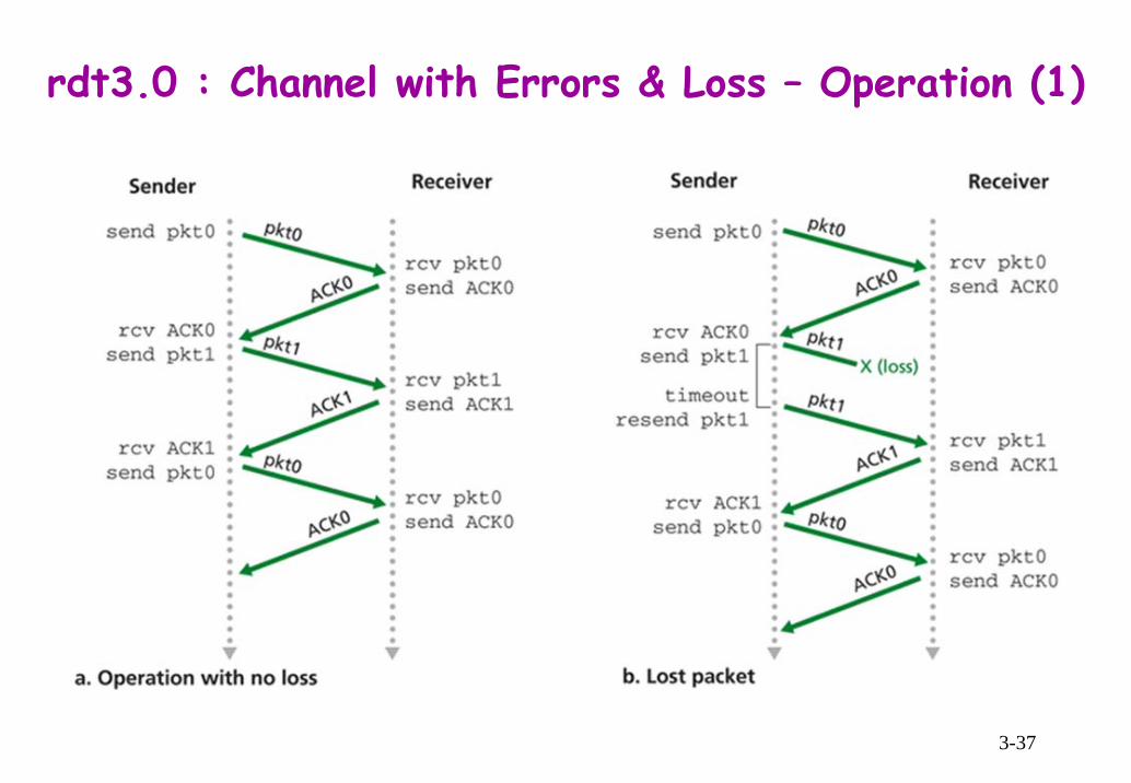
rdt3.0 : Channel with Errors and Lossnew assumptions of underlying channels :
can lose pkts (data or ACKs)
Q : how to detect pkt loss and what to do when pkt loss occurschecksum, seq #, ACKs, rexmissions are of help, but not enough
approachessender waits proper amount of time (at least round-trip delay + processing time at receiver) to convince itself of pkt lossrexmits the pkt if ACK not received within this timeif a pkt (or its ACK) just overly delayed, sender may rexmit the pkt even though it has not been lost
but, seq # handles the possibility of duplicate pkts
implementationcountdown timer set appropriately starts each time pkt is sentrexmit pkt when the timer is expired

3-36
rdt3.0 : Channel with Errors & Loss (Sender)
3-37
rdt3.0 : Channel with Errors & Loss – Operation (1)

3-38
rdt3.0 : Channel with Errors & Loss – Operation (2)

3-39
Performance of rdt3.0 (Stop-and-Wait Protocol)
assumption : ignore xmission time of ACK pkt (which extremely small) and processing time of pkt at the sender and receiversender utilization Usender : frac. of time sender is busy sending into chex) 1 Gbps link, 30 ms RTT, 1 KB packet
net protocol limits the capabilities provided by underlying net HW
9
0.008 8,000 bits/packet0.00027 ; 0.008 ms30 0.008 10 bits/sec
transsender trans
trans
tU t L RRTT t
= = ≈ = = =+ + very poor!

3-40
Pipeliningsends multiple pkts without waiting for acks
range of seq #s is increasedbuffering at sender and/or receiver required
sender : pkts that have been xmitted by not yet ackedreceiver : pkts correctly receiver
two generic forms of pipelined protocols: go-Back-N, selective repeat
sender is assumed to send 3 pktsbefore being acked
3 0.024 0.000830.008
transsender
trans
tURTT t
= = ≈+
: essentially tripled
3-41
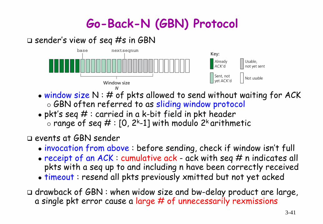
Go-Back-N (GBN) Protocolsender’s view of seq #s in GBN
window size N : # of pkts allowed to send without waiting for ACKGBN often referred to as sliding window protocol
pkt’s seq # : carried in a k-bit field in pkt headerrange of seq # : [0, 2k-1] with modulo 2k arithmetic
events at GBN senderinvocation from above : before sending, check if window isn’t fullreceipt of an ACK : cumulative ack - ack with seq # n indicates all pkts with a seq up to and including n have been correctly receivedtimeout : resend all pkts previously xmitted but not yet acked
drawback of GBN : when widow size and bw-delay product are large, a single pkt error cause a large # of unnecessarily rexmissions

3-42
Go-Back-N (GBN) Protocol : Sender
a single timer : for the oldest xmittedbut not yet acked pktupon receipt of an ACK, if there are
no outstanding unacked pkts, the timer is stoppedstill xmitted but not yet ackedpkts, the timer is restarted

3-43
Go-Back-N (GBN) Protocol : Receiverwhen pkt with seq # n is received correctly and in-order, receiver sends an ACK for pkt n and delivers data portion to upper layerreceiver discards out-of-order pkts and resends an ACK for the most recently received in-order pkt
simple receiver buffering : needn’t buffer any out-of-order pktsonly info needed : seq # of next in-order pkt, expectedseqnum

3-44
Go-Back-N (GBN) Protocol : Operation
window size = 4

3-45
Selective Repeat (SR) Protocolsender rexmits only pkts for which ACK not received ⇒ avoid unnecessary rexmissionreceiver individually acks correctly received pkts regardless of their order
out-of-order pkts are buffered until missing pkts are received

3-46
SR Protocol : Sender/Receiver Events and Actionssender
data from above : if next available seq # is in window, send pkttimeout(n) : resend pkt n, restart timer
each pkt has its own (logical) timerACK(n) in [sendbase,sendbase+N]
mark pkt n as receivedif n is equal to send_base, window base is moved forward to next unacked pkt, and xmit unxmitted pkts in advanced window
receiverpkt n in [rcvbase, rcvbase+N-1] correctly received : send ACK(n)
if not previously received, it is bufferedif n is equal to rcv_base, this pkt and previously buffered in-order pktsare delivered to upper layer, and receive window moved forward by the # of pkts delivered to upper layer
pkt n in [rcvbase-N,rcvbase-1] correctly received an ACK generated even though previously ackedif not acks, sender’s window may never move forward; for example, ackfor send_base pkt in Figure 3.23
otherwise : ignore

3-47
SR Operation

3-48
Max. Window Sizestop-and-wait protocol
window size N ≤ 2k-1 (k: # of seq field), not 2k, why?
ex) k=2 ⇒ seq #s : 0, 1, 2, 3; max N = 3SR protocol
scenarios(a) : all acks are lost
incorrectly sends duplicate as new(b) : all acks received correctly, but pkt 3
is lostreceiver can’t distinguish xmission of pkt0 in (b) from rexmission of pkt 0 in (a)
further consideration on scenario (a)A rexmits pkt 0; B receives and buffer itB sends piggybacked ack for pkt 2 that is already acked but lostA advanced window 3 0 1, and sends pkt 3B receives pkt 3, and delivers pkt 0 (no good!) in buffer and pkt 3 to upper layer
wayout : avoid overlapping of SR windowsN ≤ 2k-1, k: # of bits in seq field
A B

3-49
rdt : Comment on Packet Reorderingsince seq #s are reused, old copies of a pkt with a seq/ack # of x can appear, even though neither sender’s nor receiver’s window contains x
use of max pkt lifetime : constrain pkt to live in the net~ 3 minutes in TCP for high-speed net

3-50
Summary of rdt Mechanisms

3-51
Chap.3 Transport LayerIntroduction and Transport-Layer Services
Multiplexing and Demultiplexing
Connectionless Transport: UDP
Principle of Reliable Data Transfer
Connection-Oriented Transport: TCPTCP ConnectionTCP Segment StructureRound-Trip Time Estimation and TimeoutReliable Data TransferFlow ControlTCP Connection Management
Principles of Congestion Control
TCP Congestion Control

3-52
TCP Connectiontwo processes established connection via 3-way handshake before sending data, and initialize TCP variables
full duplex : bi-directional flow bw processes in the same connpoint-to-point : bw one sender and one receiver
multicasting is not possible with TCPa stream of data passes through a socket into send buffer
TCP grab chunks of data from send buffermax seg size (MSS) : max amount of app-layer data in seg
set based on Path MTU of link-layertypically, 1,460 bytes, 536 bytes, or 512 bytes
each side of conn has send buffer and receive buffer

3-53
TCP Segment Structure
for reliable data xfercount in bytes, not pkts
for flow control, # of bytesreceiver willing to receive
4-bit # countingin 32-bit words
typically, empty- time-stamping- mss, window scaling factornegotiation, etc.
for error detection
• ACK : indicates value in ack field is valid• SYN, RST, FIN : used for connection setup and teardown• PSH : receiver should pass data to upper layer immediately• URG : indicates there is an urgent data in the seg marked by sending-side upper layer
- urgent data pointer indicates the last bytes of urgent data- generally, PSH and URG are not used

3-54
Seq Numbers and Ack Numbersseq # : 1st byte in seg over xmitted bytes stream, not over series of xmitted segs
TCP implicitly number each byte in data stream
initial seq # is chosen randomly rather than set 0, why?
ack # : seq # of next byte expected from other sidecumulative ACK
Q : how to handle out-of-order segs at receiver? discard or buffer waiting for missing bytes to fill in the gaps
TCP leaves the decision up to implementation, but the latter is chosen in practice

3-55
Telnet : Case Study of Seq and Ack Numberseach ch typed by A is echoed back by B and displayed on A’s screen
ACK piggybacked on B-to-A data seg
explicit ACK with no data

3-56
Estimating Round-Trip Time (RTT)clearly, TCP timeout value > RTTQ : How much larger? How to estimate RTT? Each seg exploited in
estimating RTT? …
estimating RTTSampleRTT : time measured from seg xmission until ACK receipt
measured not for every seg xmitted, but for one of xmitted segsapproximately once every RTTrexmitted segs are not considered in measurementsfluctuates from seg to seg : atypical ⇒ needs some sort of avg
Exponential Weighted Moving Average (EWMA) of RTTavg several recent measurements, not just current SampleRTTEstimatedRTT = (1 - α)⋅EstimatedRTT + α⋅SampleRTT
recommended value of α : 0.125more weight on recent samples than on old samplesweight of a given sampleRTT decays exponentially fast as updates proceed

3-57
RTT Samples and RTT Estimates
variations in the Sample RTT are smoothed out in Estimated RTT

3-58
Retransmission Timeout IntervalDevRTT, variation of RTT : an estimate of how much SampleRTTdeviates from EstimatedRTTDevRTT = (1-β)⋅DevRTT + β⋅|SampleRTT−EstimatedRTT|
large (or small) when there is a lot of (or little) fluctuationrecommended value of β : 0.25
TCP’s timeout intervalshould be larger, or unnecessarily rexmit!but, if too much larger, TCP wouldn’t quickly rexmit, leading to large data transfer delaythus, timeout interval should be EstimatedRTT plus some safety margin that varies as a function of fluctuation in SampleRTTTimeoutInterval = EstimatedRTT + 4⋅DevRTT

3-59
TCP Reliable Data Transferreliable data transfer service on top of IP’s unreliable service
seq # : to identify lost and duplicate segscumulative ack : positive ACK (i.e, NAK-free)timer
a single rexmission timer is recommended [RFC 2988], even if there are multiple xmitted but not yet acked segsrexmissions triggered by
when timed out3 duplicate acks at sender : fast rexmit in certain versions
We’ll discuss TCP rdt in two incremental stepshighly simplified description : only timeouts consideredmore subtle description : duplicate acks as well as timeouts considered
in both cases, error and flow control are not taken into account

3-60
Simplified TCP Sender
seq # is byte-stream # of the first data byte in seg
TimeoutInterval = EstimatedRTT + 4⋅DevRTT
some not-yet-acked segs are ackedmove window forward

3-61
TCP Retransmission Scenarios
rexmission due to a lost ack cumulative ack avoids rexmission of first seg
segment 100 not rexmitted
SendBase=100
SendBase=120
SendBase=120
SendBase=120
SendBase=100

3-62
TCP Modifications : Doubling Timeout Intervalat each timeout, TCP rexmits and set next timeout interval to twice the previous value⇒ timeout intervals grow exponentially after each rexmission
but, for the other events (i.e., data received from app and ACK received) timeout interval is derived from most recent values ofEstimatedRTT and DevRTT

3-63
TCP ACK Gen Recommendation [RFC 1122, 2581]
timeout period can be relatively long ⇒ may increase e-t-e delay
when sending a large # of segs back to back (such as a large file), if one seg is lost, there will be likely many back-to-back ACKs for it

3-64
TCP Modifications : TCP Fast RetransmitTCP Fast Retransmit : rexmits a (missing) seg before its timer expiration, if TCP sender receives 3 duplicate ACKs
if (y > SendBase) { // event: ACK received,with ACK field value of y
SendBase = yif (there are currently not-yet-
acked segs)start timer
} else { // a duplicate ACK for already ACKed
segmentincrement count of dup ACKs
received for yif (count of dup ACKs received
for y = 3) // TCP fast retransmitresend seg with seq # y
}

3-65
Is TCP Go-Back-N or Selective Repeat?similarity of TCP with Go-Back-N
TCP : cumulative ack for the last correctively received, in-order segcumulative and correctly received but out-of-order segs are not individually acked
⇒ TCP sender need only maintain SendBase and NextSeqNumdifferences bw TCP and Go-Back-N : many TCP implementations
buffer correctly received but out-of-order segs rather than discardalso, suppose a seq of segs 1, 2, … N, are received correctively in-order, ACK(n), n < N, gets lost, and remaining N-1 acks arrive at sender before their respective timeouts
TCP rexmits at most one seg, i.e., seg n, instead of pkts, n, n+1, …, NTCP wouldn’t even rexmit seg n if ACK(n+1) arrived before timeout for seg n
a modification to TCP in [RFC 2018] : selective acknowledgementTCP receiver acks out-of-order segs selectively rather than cumulativelywhen combined with selective rexmission - skipping segs selectively acked by receiver – TCP looks a lot like generic SR protocol
Thus, TCP can be categorized as a hybrid of GBN and SR protocols

3-66
Flow Control : Goalreceiving app may not read data in rcv buffer as quickly as supposed to be
it may be busy with some other taskmay relatively slow at reading data, leading to overflowing receiver’s buffer by too much data too quickly sent by sender
flow control : a speed-matching service, matching sending rate against reading rate of receiving app
goal : eliminate possibility of sender overflowing receiver buffer
(note) to make the discussion simple, TCP receiver is assumed todiscard out-of-order segs

3-67
Flow Control : How It Works?
at receivernot to overflow : LastByteRcvd – LastByteRead ≤ RcvBufferLastByteRcvd – LastByteRead : # of bytes received not yet read RevWindow advertising : RcvWindow placed in receive window field in every seg sent to senderRcvWindow = RcvBuffer - [LastByteRcvd - LastByteRead]
at sender : limits unacked # of bytes to RcvWindowLastByteSent – LastByteAcked ≤ RcvWindowLastByteSent – LastByteAcked : # of byte sent but not yet acked
RevBuffer : size of buffer space allocated to a connRcvWindow : amount of free buffer space at rcv’s buffer
initial value of RcvWindow = RevBuffer
LastByteRcvd, LastByteRead : variables at receiverLastByteSent, LastByteAcked : variables at sender

3-68
Flow Control : Avoiding Sender Blockingsuppose A is sending to B, B’s rcv buffer becomes full so that RcvWindow = 0, and after advertising RcvWindow = 0 to A, B has nothing to send to A
note that TCP at B sends a seg only if it has data or ack to sendthere is no way for B to inform A of some space having opened up in B’s rcv buffer ⇒ A is blocked, and can’t xmit any more!
wayout : A continue to send segs with one data byte when RcvWindow = 0, which will be acked
eventually, the buffer will begin to empty and ack will contain a nonzero RcvWindow value

3-69
TCP Connection Management : Establishment
3-way handshake1. client sends SYN seg to server
contains no app datarandomly select client initial seq #
2. server replies with SYNACK segserver allocates buffers and variables to the connectioncontains no app datarandomly select server initial seq #
3. client replies with ACK segclient allocates buffers and variables to the connectionmay contain data
SYN segment
SYNACK segment
ACK segment

3-70
TCP Connection Management : Termination
Either of client or server can end the TCP connection
duration of TIME_WAIT period : implementation dependent
typically, 30 secs, 1 min, 2 mins
RST seg : seg with RST flag set to 1sent when receiving a TCP segwhose dst port # or src IP addr is not matched with on-going one

3-71
TCP State Transition : ClientSocket clientSocket = new Socket("hostname","port#");

3-72
TCP State Transition : ServerServerSocket welcomeSocket = new ServerSocket(port#)
Socket connectionSocket = welcomeSocket.accept();
3-73
Chap.3 Transport LayerIntroduction and Transport-Layer Services
Multiplexing and Demultiplexing
Connectionless Transport: UDP
Principle of Reliable Data Transfer
Connection-Oriented Transport: TCP
Principles of Congestion ControlThe Causes and the Costs of CongestionApproaches to Congestion ControlNetwork-Assisted Congestion-Control Example for ATM AVR
TCP Congestion Control
3-74
Preliminary of Congestion Controlpkt loss (at least, perceived by sender) results from overflowing of router buffers as the net becomes congested
rexmission treats a symptom, but not the cause, of net congestion
cause of net congestion : too many sources attempting to send data at too high a rate
basic idea of wayout : throttle senders in face of net congestionwhat’s different from flow control?
ranked high in top-10 list of networking problem

3-75
Causes and Costs of Congestion : Scenario 1assumptions
no error control, flow control, and congestion controlhost A and B send data at an avg rate of λin bytes/sec, respectivelyshare a router with outgoing link capacity of R and infinite buffer spaceignore additional header info (transport-layer and lower-layer)
cost of congested net : avg delay grows unboundedly large as arrival rate nears link capacity

3-76
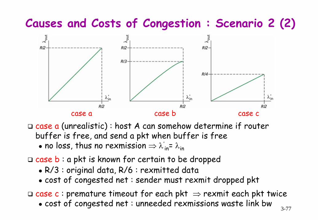
Causes and Costs of Congestion : Scenario 2 (1)assumptions
one finite buffer spaceeach host with same λin, retransmit dropped packets
3-77
case a (unrealistic) : host A can somehow determine if router buffer is free, and send a pkt when buffer is free
no loss, thus no rexmission ⇒ λ’in= λin
case b : a pkt is known for certain to be droppedR/3 : original data, R/6 : rexmitted datacost of congested net : sender must rexmit dropped pkt
case c : premature timeout for each pkt ⇒ rexmit each pkt twicecost of congested net : unneeded rexmissions waste link bw
Causes and Costs of Congestion : Scenario 2 (2)
case a case b case c

3-78
Causes and Costs of Congestion : Scenario 3assumptions
4 routers, each with finite buffer space and link capacity of Reach of 4 hosts has same λin, rexmits over 2-hop paths
• consider A→C conn• a pkt dropped at R2 (due to high λin
from B) wastes the work done by R1
cost of congested net : a pktdropped at some point wastes the xmission capacity up to that point

3-79
Two Broad Approaches to Congestion Controlend-end congestion control
no explicit support (by feedback) from net layercongestion inferred by end-system based on observed net behavior, e.g., pkt loss and delayapproach taken by TCP
congestion is inferred by TCP seg loss indicated by timeout or triple duplicate acks
network-assisted congestion controlrouters provide explicit feedback to end systems regarding congestion state in the netsingle bit indication
SNA, DECnet, TCP/IP ECN [RFC2481], ATM AVR congestion control
explicit rate : the rate router can support on its outgoing link

3-80
Two Types of Feedback of Congestion Infodirect feedback : from a router to the sender by using choke pktfeedback via receiver
router mark/update a field in a pkt flowing forward to indicate congestionupon receipt of the pkt, receiver notifies sender of congestion

3-81
ATM ABR Congestion ControlAsynchronous Transfer Mode (ATM)
a virtual-circuit switching architectureinfo delivered in fixed size cell of 53 bytes each switch on src-to-dst path maintains per-VC state
Available Bit Rate (ABR) : an elastic serviceif net underloaded, use as much as available bandwidthif net congested, sender rate is throttled to predetermined min guaranteed rate
Resource Management (RM) cellsinterspersed with data cells, conveying congestion-related info
rate of RM cell interspersion : tunable parameterdefault value : one every 32 data cells
provides both feedback-via-receiver and direct feedbacksent by src flowing thru switches to dst, and back to srcswitch possibly generate RM cell itself, and send directly to src

3-82
Mechanisms of Congestion Indication in ATM AVR
Explicit Forward Congestion Indication (EFCI) bitEFCI bit in a data cell is set to 1 at congested switchif a data cell preceding RM cell has EFCI set, dst sets CI bit of RM cell, and sends it back to src
CI (Congestion Indication) and NI (No Increase) bitsset by congested switch, NI/CI bit for mild/severe congestiondst sends the RM cell back to src with CI and NI bits intact
Explicit Rate (ER) : two-byte field in RM cellcongested switch may lower ER value in a passing RM cellwhen retuned back to src, it contains max supportable rate on the path

3-83
Chap.3 Transport LayerIntroduction and Transport-Layer Services
Multiplexing and Demultiplexing
Connectionless Transport : UDP
Principle of Reliable Data Transfer
Connection-Oriented Transport : TCP
Principles of Congestion Control
TCP Congestion ControlFairnessTCP Delay Modeling

3-84
Preliminary of TCP Congestion Control (1)basic idea of TCP congestion control : limit sending rate based on the network congestion perceived by sender
increase/reduce sending rate when sender perceives little/∗congestion along the path bw itself and dst
to keep the description concrete, sending a large file is assumed
How does sender limit sending rate?LastByteSent - LastByteAcked ≤ min{CongWin, RcvWindow} (1)CongWin : a variable limiting sending rate due to perceive congestionhenceforth, RcvWindow constraint ignored in order to focus on congestion control(1) limits the amount of unacked data, thus the sending rate
consider conn for which loss and xmission delay are negligible
≈sending ratethenR
, TT
CongWin
3-85
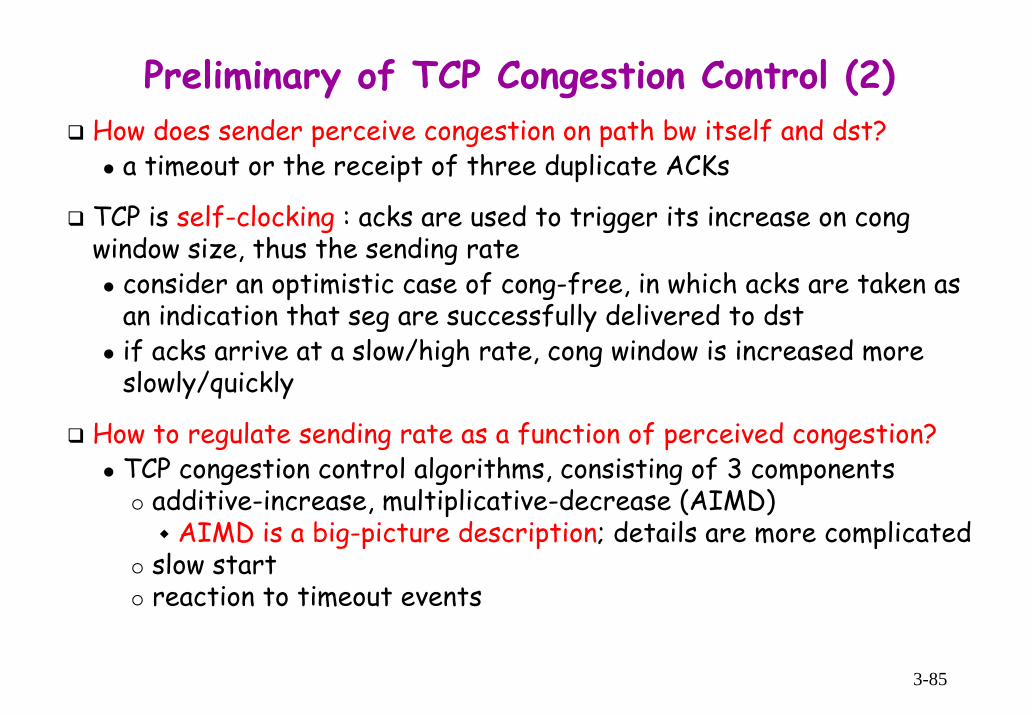
Preliminary of TCP Congestion Control (2)How does sender perceive congestion on path bw itself and dst?
a timeout or the receipt of three duplicate ACKs
TCP is self-clocking : acks are used to trigger its increase on cong window size, thus the sending rate
consider an optimistic case of cong-free, in which acks are taken as an indication that seg are successfully delivered to dstif acks arrive at a slow/high rate, cong window is increased more slowly/quickly
How to regulate sending rate as a function of perceived congestion?TCP congestion control algorithms, consisting of 3 components
additive-increase, multiplicative-decrease (AIMD)AIMD is a big-picture description; details are more complicated
slow startreaction to timeout events

3-86
Additive-Increase, Mulitplicative-Decreasemultiplicative decrease : cut CongWin in half down to 1 MSS when detecting a lossadditive increase: increase CongWin by 1 MSS every RTT until a loss detected (i.e., when perceiving e-t-e path is congestion-free)
commonly, accomplished by increasing CongWin by MSS⋅(MSS/CongWin) bytes for each receipt of new ackex) MSS=1,460 bytes, ConWin=14,600 bytes ⇒ 10 segs sent within RTT
an ACK for a seg increases CongWin by 1/10⋅MSS, thus after ack for all 10 segs (thus, for one RTT) CongWin is increased by MSS
congestion avoidance : linear increase phase of TCP cong control
saw-toothed pattern of CongWin

3-87
TCP Slow StartWhen a TCP conn begins, CongWin is typically initialized to 1 MSS ⇒ initial rate ≈ MSS/RTT
ex) MSS = 500 bytes, RTT = 200 msec ⇒ initial sending rate : only about 20 kbps
linear increase at init. phase results in a waste of bw, considering available bw may be >> MSS/RTTdesirable to quickly ramp up to some respectable rate
slow start (SS) : during initial phase, increase sending rate exponentially fast by doubling CongWin every RTT until a loss occurs
achieved by increasing CongWin by 1 MSS for receipt of ack

3-88
Reaction to CongestionQ: When does CongWin switch from exponential increase to linear increase? A: when CongWin is reached to Threshold
Threshold : a variable set to a half of CongWin just before a lossinitially set large, typically 65 Kbytes, so that it has no initial effectmaintained until the next loss
TCP Tahoe, early version of TCPCongWin is cut to 1 MSS both for a timeout and for 3 duplicate acks
Jacobson’s algorithm [Jacobson 1988]TCP Reno [RFC2581, Stevens ’94] : reaction to loss depends on loss type
for 3 duplicate acks receipt : CongWin is cut in half, then grows linearly for a timeout event : CongWin is set to 1 MSS (SS phase), then grows exponentially to a Threshold, then grows linearly (CA phase)idea : 3 dup acks anyhow indicates capability of delivering some pkts
TCP Reno cancels SS phase after a triple duplicate ack : fast recoverymany variations of TCP Reno [RFC 3782, RFC 2018]
TCP Vegas [Brakmo 1995]idea : early warning - detect congestion in routers before pkt loss occurs when this imminent pkt loss, predicted by observing RTT, is detected, CongWin is lowered linearly; the longer the RTT, the greater the congestion

3-89
TCP Congestion Control Algorithms
• initial value of Threshold = 8 MSS• triple duplicate acks just after 8th round

3-90
TCP Reno Congestion Control Algorithm[RFC 2581, Stevens 1994]

3-91
Steady-State Behavior of a TCP ConnectionConsider a highly simplified macroscopic model for steady-state behavior of TCP
SS phases ignored since they are typically very shortLetting W be the window size when a loss event occurs, RTT and W are assumed to be approximately constant during a conn
Q : What’s avg throughput of a long-lived TCP conn as a function of window size and RTT?
A :
a pkt is dropped when the rate increases to W/RTTthen the rate is cut in half and linearly increases by MSS/RTT every RTT until it again reaches W/RTTthis process repeats over and over again
⋅=
0.75 Wavg throughput of a TCP connection (2)RTT

3-92
TCP FuturesTCP congestion control has evolved over the years and continue to evolve
[RFC 2581] : a summary as of the late 1990s[Floyd 2001] : some recent developmentstraditional scheme is not necessarily good for today’s HTTP-dominated Internet or for a future Internet service
ex) Consider a high-speed TCP conn with 1500-byte segments, 100ms RTT, and want to achieve 10 Gbps throughput through this conn
to meet this, from (2) required window size is
this is a lot of segs, so that there is high possibility of errors, leading us to derive a relationship bw throughput and error rate [prob. P39]
⇒ L = 2⋅10-10, i.e., one loss for every 5 ⋅10-9segs : unattainably low!
⇒ new vers of TCP required for high-speed environments [RFC 3649, Jin 2004]
= ⋅ = ⋅ ⋅ = ≈×
710RTT 0.1 sec 1 10W tput 10 bits/sec 111,111 segs
0.75 0.75 1,500 8 bits/seg 90
⋅=
1.22 MSSavg throughput of a TCP connRTT L
high bandwidth delay product

3-93
TCP Fairness (1)suppose K TCP conns pass though a bottleneck link bw of R, with each connsending a large file⇒ avg xmission rate of each conn is approximately R/K
TCP congestion control is fair : each conn gets an equal share of bottleneck link’s bw among competing TCP conns
consider a link of R shared by two TCP conn, with idealized assumptionssame MSS and RTT, sending a large amount of data, operating in CA mode (AIMD) at all times, i.e., ignore SS phase

3-94
TCP Fairness (2)
bw realized by two conns fluctuates along equal bw share line, regardless of their initial rates
in practice, RTT value differs from conn to conn
conns with a smaller RTT grab the available bw more quickly (i.e., open their cong window faster), thus get higher throughput than those connswith larger RTTs
ideal operating point
CA phase
loss occurs
A
D
C
B

3-95
Some other Fairness IssuesFairness and UDP
multimedia apps, e.g., Internet phone and video conferencing do not want their rate throttled even if net is congestedthus runs over UDP rather than TCP, pumping audio/video at const rate, and occasionally lose pkt rather than reducing rate when congested ⇒ UDP sources may crowd out TCP trafficresearch issue : TCP-friendly cong control
goal : let UDP traffic behave fairly, thus prevent the Internet from flooding
Fairness and parallel TCP connectionsa session can open multiple parallel TCP conn’s bw C/S, thus gets a large portion of bw in a congested link
a Web browser to xfer multiple objects in a page ex) a link of rate R supporting 9 ongoing C/S apps
a new app, asking for 1 TCP conn, gets an equal share of R/10a new app, asking for 11 TCP conns, gets an unfair rate of R/2

3-96
TCP Delay ModelingWe’d compute the time for TCP to send an object for some simple models
latency : defined as the time from when a client initiate a TCP conn until the time at which it receives the requested object
assumptions : made in order not to obscure the central issuessimple one-link net of rate R bpsamount of data sender can xmit is limited solely by cong windowpkts are neither lost or corrupted, thus no rexmissionall protocol header overheads : ignoredobject consist of an integer # of MSS
O: object size [bits], S : seg size [bits] (e.g., 536 bits)xmission time for segs including control info : ignoredinitial threshold of TCP cong control scheme is so large as not to be attained by cong window
without cong window constraint : the latency is 2⋅RTT+O/Rclearly, SS procedure, dynamic cong window increase this minimal latency

3-97
Static Congestion Window (1)W : a positive integer, denoting a fixed-size static congestion window
upon receipt of rqst, server immediately sends W segs back to back to client, then one seg for each ack from client
1st case : WS/R > RTT+S/Rack for 1st seg in 1st window received before sending 1st
window’s worth of segsserver xmit segs continuously until entire object is xmittedthus, the latency is2⋅RTT+O/R
W=4

3-98
Static Congestion Window (2)
2nd case : WS/R < RTT+S/Rack for 1st seg in 1st window received after sending 1st window’s worth of segs
latency = setup time + time for xmittingobject + sum of times in idle state
let K : # of windows covering objectK = O/WS or ⎡K⎤ if K is not an integer
# of times being in idle state = K-1duration of server being in idle stateS/R+RTT-WS/R
thus, the latency is2⋅RTT+O/R+(K-1)[S/R+RTT-WS/R]+
where [x]+ = max(x,0)
W=2
transmitting stateidle state

3-99
Dynamic Congestion Window (1)cong window grows according to slow start, i.e., doubled every RTT
O/S : # of segs in the object# of segs in kth window : 2k-1
K : # of windows covering object
xmission time of kth window = (S/R)2k-1
duration in idle state of kth window=[S/R+RTT-2k-1(S/R)]+
O/S=15K=4Q=2
P=min{Q,K-1}=2
−
−
⎧ ⎫= + + + ≥⎨ ⎬⎩ ⎭⎧ ⎫= − ≥⎨ ⎬⎩ ⎭⎧ ⎫⎛ ⎞= ≥ +⎨ ⎬⎜ ⎟
⎝ ⎠⎩ ⎭⎡ ⎤⎛ ⎞= +⎜ ⎟⎢ ⎥⎝ ⎠⎢ ⎥
0 1 1
1
2
2
min : 2 2 2
min : 2 1
min : log 1
log 1
k
k
OK kS
OkSOk kS
OS

3-100
Dynamic Congestion Window (2)latency = setup time + time for xmitting object + Σ times in idle state
Q : # of times server being idle if object were of infinite size
actual # of times server is idle is P=min{Q, K-1}, then (3) becomes
+−−
=
⎡ ⎤= ⋅ + + + −⎢ ⎥⎣ ⎦∑
11
1latency 2 2 (3)
Kk
k
O S SRTT RTTR R R
{ }− −⎧ ⎫= + − ≥ = ≤ +⎨ ⎬⎩ ⎭
⎧ ⎫ ⎢ ⎥⎛ ⎞ ⎛ ⎞= ≤ + + = + +⎨ ⎬⎜ ⎟ ⎜ ⎟⎢ ⎥⎝ ⎠ ⎝ ⎠⎩ ⎭ ⎣ ⎦
1 1
2 2
max : 2 0 max : 2 1/
max : log 1 1 log 1 1/ /
k kS S RTTQ k RTT kR R S R
RTT RTTk kS R S R
( )
−
=
−
=
⎡ ⎤= ⋅ + + + −⎢ ⎥⎣ ⎦⎡ ⎤= ⋅ + + + −⎢ ⎥⎣⎡ ⎤⋅ + + + − −
⎦
⎦
⎥= ⎢⎣
∑
∑
1
1
1
1
latency 2 2
2 2
2 2 (1 4)P
Pk
kP
k
k
O S SRTT RTTR R RO S SRTT P RTTR R RO S SRTT P RTTR R R

3-101
Dynamic Congestion Window (3)comparing TCP latency of (4) with minimal latency
slow start significantly increase latency when object size is relatively small (implicitly, high xmission rate) and RTT is relatively large
this is often the case with the Web
See the examples in the text
( ) ( )( )( )
( )( ) ( )
⎡ ⎤⎡ ⎤+ − −⎣ ⎦ ⎣ ⎦= ++
⎡ ⎤+ + −⎣ ⎦= + ≤ ++ +
1 2 1latency 1minimal latency 2
1 21 1
2 2
p
p
P S R RTT S R RTTO R RTT
P S R RTT P PO R RTT O R RTT
latency contributed by slow start

3-102
HTTP ModelingAssume Web page consists of
1 base HTML page (of size O bits)M images (each of size O bits)
non-persistent HTTPM+1 TCP conns in seriesresponse time = 2⋅(M+1)RTT + (M+1)O/R + sum of idle times
persistent HTTP2 RTT to request and receive base HTML file1 RTT to request and receive M imagesresponse time = 3⋅RTT + (M+1)O/R + sum of idle times
non-persistent HTTP with X parallel connssuppose M/X is integer1 TCP conn for base fileM/X sets of parallel conns for imagesresponse time = 2⋅(M/X + 1)RTT + (M+1)O/R + sum of idle times