computer networks lecture 6: data link layer june 2009 local area networks ethernet, wireless, ppp,...
TRANSCRIPT

Computer Networks
Lecture 6: Data Link Layer
June 2009
Local Area NetworksEthernet, Wireless,
PPP, ATM

3 Generations of Ethernet

Traditional Ethernet
1976, Xerox’s Palo Alto Research Center (PARC)
Connection-less: no flow/error control Use 1-persistent CSMA/CD MAC sublayer Physical layer Physical layer implementation Bridged Ethernet Switched Ethernet Full duplex Ethernet

Outline
LAN addresses and ARP Ethernet Hubs, bridges, and switches Wireless links and LANs PPP ATM

LAN technologies
Data link layer so far: services, error detection/correction, multiple
access
Next: LAN technologies addressing Ethernet hubs, bridges, switches 802.11 PPP ATM

LAN Addresses
32-bit IP address: network-layer address used to get datagram to destination IP network
(recall IP network definition)
LAN (or MAC or physical or Ethernet) address:
used to get datagram from one interface to another physically-connected interface (same network)
48 bit MAC address (for most LANs) burned in the adapter ROM

LAN AddressesEach adapter on LAN has unique LAN address
LAN Address (more)
MAC address allocation administered by IEEE
A manufacturer (Dlink, 3Com, Cisco…) buys portion of MAC address space (to assure uniqueness) First 24 bits : identifies manufacturer Last 24 bits: with one manufacturer

LAN Address (more)
MAC flat address => portability can move LAN card from one LAN to another
IP hierarchical address NOT portable depends on IP network to which node is
attached Analogy: (a) MAC address: like Mobile phone
Number (b) IP address: like postal address Problem
MAC IP address

Recall earlier routing discussion
223.1.1.1
223.1.1.2
223.1.1.3
223.1.1.4 223.1.2.9
223.1.2.2
223.1.2.1
223.1.3.2223.1.3.1
223.1.3.27
A
BE
Starting at A, given IP datagram addressed to B:
look up net. address of B, find B on same net. as A
link layer send datagram to B inside link-layer frame
B’s MACaddr
A’s MACaddr
A’s IPaddr
B’s IPaddr
IP payload
datagramframe
frame source,dest address
datagram source,dest address

ARP: Address Resolution Protocol
Each IP node (Host, Router) on LAN has ARP table
ARP Table: IP/MAC address mappings for some LAN nodes
< IP address; MAC address; TTL>
TTL (Time To Live): time after which address mapping will be forgotten (typically 20 min)
Question: how to determineMAC address of Bknowing B’s IP address?
ARP protocol
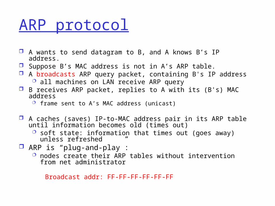
A wants to send datagram to B, and A knows B’s IP address. Suppose B’s MAC address is not in A’s ARP table. A broadcasts ARP query packet, containing B's IP address
all machines on LAN receive ARP query B receives ARP packet, replies to A with its (B's) MAC address
frame sent to A’s MAC address (unicast)
A caches (saves) IP-to-MAC address pair in its ARP table until information becomes old (times out) soft state: information that times out (goes away) unless
refreshed ARP is “plug-and-play”:
nodes create their ARP tables without intervention from net administrator
Broadcast addr: FF-FF-FF-FF-FF-FF
Outline
LAN addresses and ARP Ethernet Hubs, bridges, and switches Wireless links and LANs PPP ATM
Ethernet
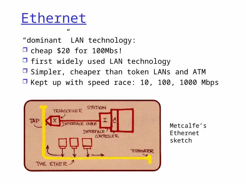
“ dominant” LAN technology: cheap $20 for 100Mbs! first widely used LAN technology Simpler, cheaper than token LANs and ATM Kept up with speed race: 10, 100, 1000 Mbps
Metcalfe’s Ethernetsketch

Ethernet Frame Structure (more) Type: indicates the higher layer protocol,
mostly IP but others may be supported such as Novell IPX and AppleTalk)
CRC: checked at receiver, if error is detected, the frame is simply dropped
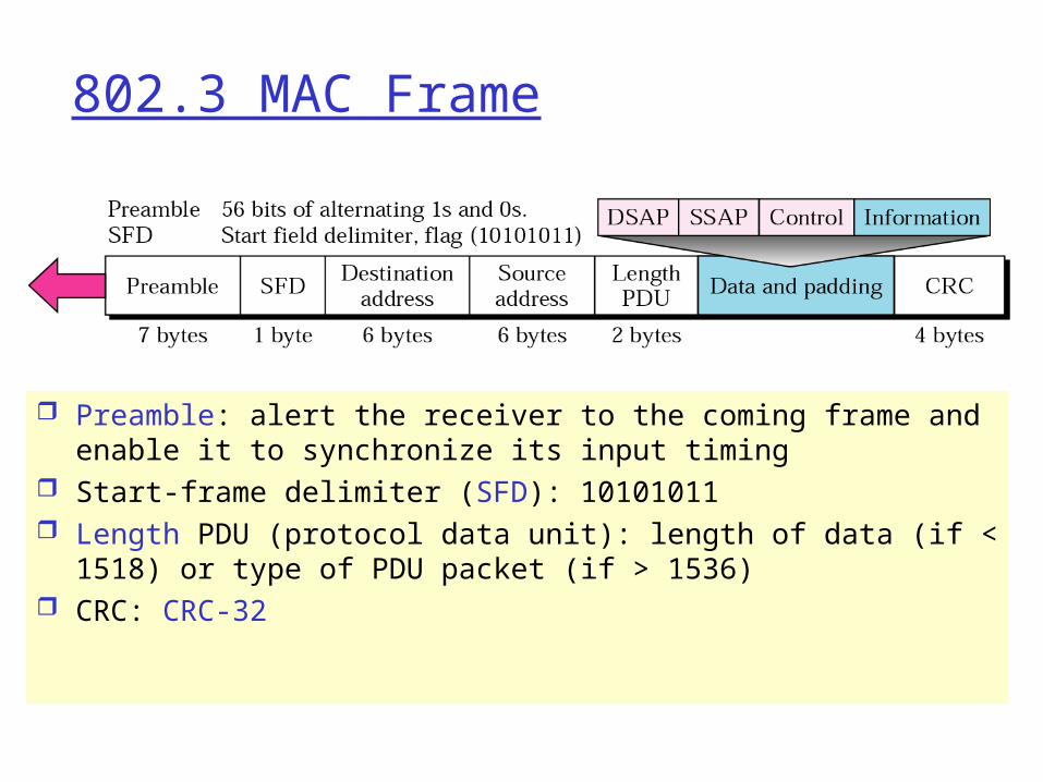
802.3 MAC Frame
Preamble: alert the receiver to the coming frame and enable it to synchronize its input timing
Start-frame delimiter (SFD): 10101011 Length PDU (protocol data unit): length of data (if < 1518) or
type of PDU packet (if > 1536) CRC: CRC-32

Frame Size
Minimum length is set to ensure that a frame is sent before collision is detected (if any)
Why maximum length = 1500 bytes? (only historical) If upper-level packet size > 1518 => bit padding
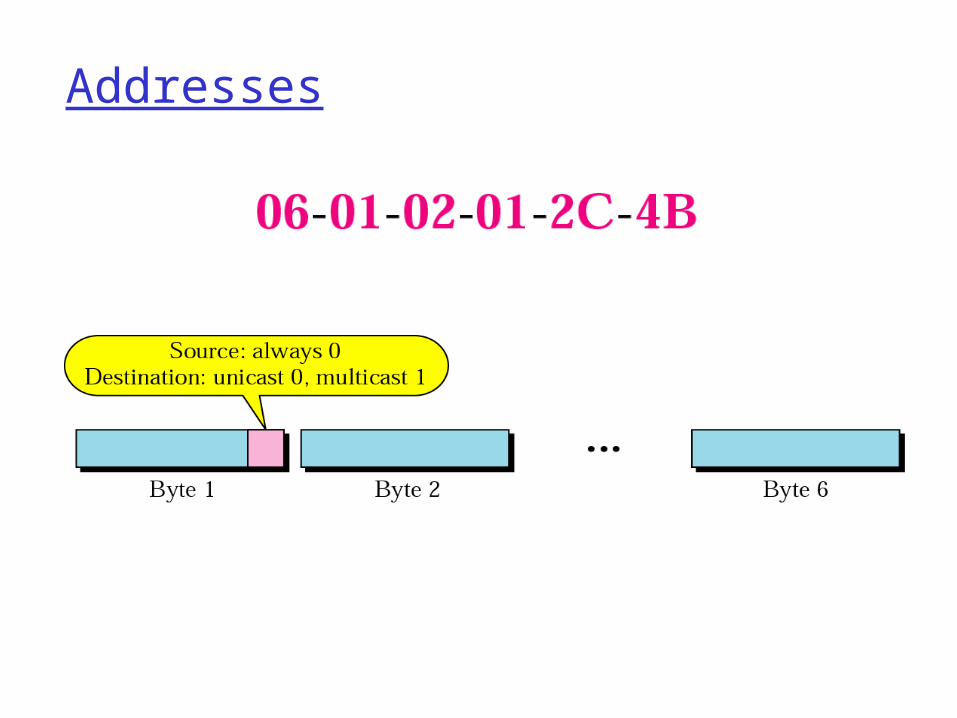
Addresses

Unreliable, connectionless service Connectionless: No handshaking between
sending and receiving adapter. Unreliable: receiving adapter doesn’t send
acks or nacks to sending adapter stream of datagrams passed to network layer can
have gaps gaps will be filled if app is using TCP otherwise, app will see the gaps

Ethernet uses CSMA/CD
No slots adapter doesn’t
transmit if it senses that some other adapter is transmitting, that is, carrier sense
transmitting adapter aborts when it senses that another adapter is transmitting, that is, collision detection
Before attempting a retransmission, adapter waits a random time, that is, random access

Ethernet CSMA/CD algorithm
1. Adaptor gets datagram from and creates frame
2. If adapter senses channel idle, it starts to transmit frame. If it senses channel busy, waits until channel idle and then transmits
3. If adapter transmits entire frame without detecting another transmission, the adapter is done with frame !
4. If adapter detects another transmission while transmitting, aborts and sends jam signal
5. After aborting, adapter enters exponential backoff: after the nth collision, adapter chooses a K at random from {0,1,2,…,2m-1}. Adapter waits K*512 bit times and returns to Step 2
m = min(n,10)

Ethernet’s CSMA/CD (more)
Jam Signal: make sure all other transmitters are aware of collision; 48 bits;
Bit time: .1 microsec for 10 Mbps Ethernet ;for K=1023, wait time is about 50 msec
Exponential Backoff: Goal: adapt retransmission
attempts to estimated current load heavy load: random wait
will be longer first collision: choose K
from {0,1}; delay is K x 512 bit transmission times
after second collision: choose K from {0,1,2,3}…
after ten collisions, choose K from {0,1,2,3,4,…,1023}

CSMA/CD efficiency Tprop = max prop between 2 nodes in LAN
ttrans = time to transmit max-size frame
Efficiency goes to 1 as tprop goes to 0
Goes to 1 as ttrans goes to infinity Much better than ALOHA, but still decentralized, simple, and cheap
transprop tt /51
1efficiency

Physical Layer
Encode/decode data
Medium-independent
For external receiver, MDI can be a tap or a tee connectorFor internal receiver, MDI can be a jack

Physical Layer Signaling (PLS)
For 10Mbps, bandwidth of 20Mbaud is needed

Attachment Unit Interface (AUI)
AUI: medium independentIf MAU is changed, PLS is not

MAU (Transceiver)
MAU: create appropriate signal for each mediumTransmitter, receiver, detect collision
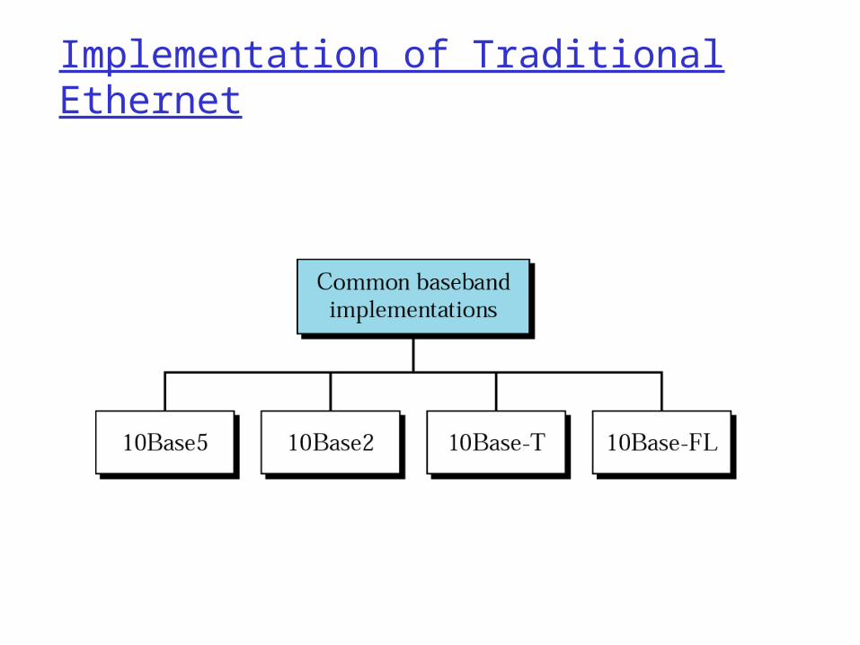
Implementation of Traditional Ethernet
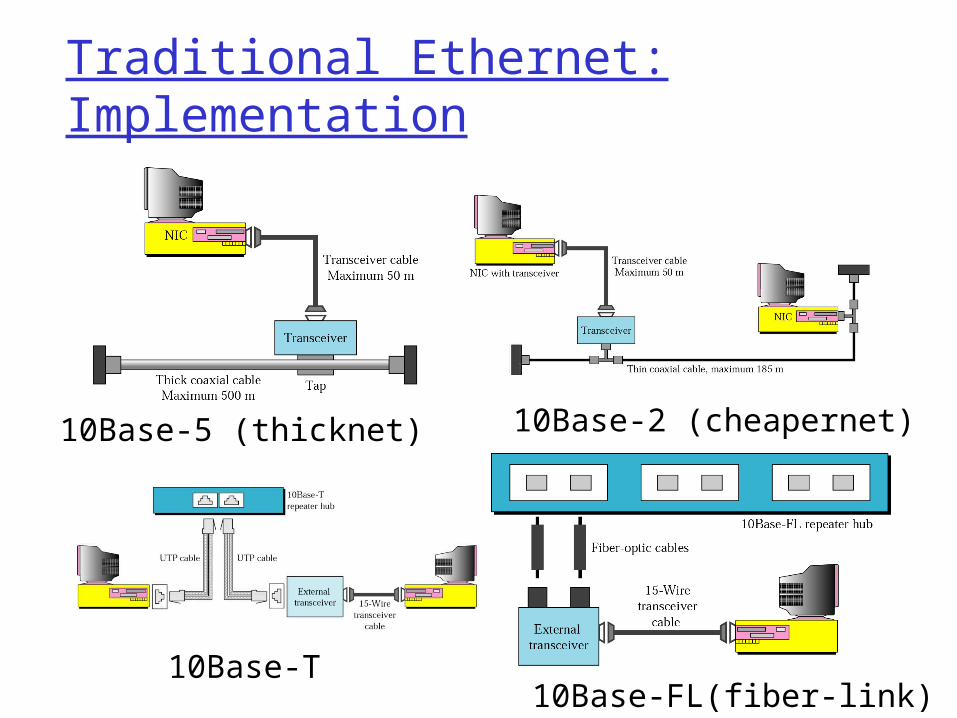
Traditional Ethernet: Implementation
10Base-5 (thicknet) 10Base-2 (cheapernet)
10Base-T10Base-FL(fiber-link)

Ethernet Technologies: 10Base2 10: 10Mbps; 2: under 200 meters max cable length thin coaxial cable in a bus topology
repeaters used to connect up to multiple segments repeater repeats bits it hears on one interface to its other interfaces: physical layer device only! has become a legacy technology

10BaseT and 100BaseT 10/100 Mbps rate; latter called “fast ethernet” T stands for Twisted Pair Nodes connect to a hub: “star topology”; 100 m max distance between nodes and hub
Hubs are essentially physical-layer repeaters: bits coming in one link go out all other links no frame buffering no CSMA/CD at hub: adapters detect collisions provides net management functionality
hub
nodes

Manchester encoding
Used in 10BaseT, 10Base2 Each bit has a transition Allows clocks in sending and receiving nodes
to synchronize to each other no need for a centralized, global clock among nodes!

Gbit Ethernet
use standard Ethernet frame format allows for point-to-point links and shared
broadcast channels in shared mode, CSMA/CD is used; short
distances between nodes to be efficient uses hubs, called here “Buffered Distributors” Full-Duplex at 1 Gbps for point-to-point links 10 Gbps now !

Outline
LAN addresses and ARP Ethernet Hubs, bridges, and switches Wireless links and LANs PPP ATM

Bridged Ethernet
Collision separation + Bandwidth increase

Switched Ethernet
Only station and switch share the bandwidth => 5Mbps each

Full-duplex Switched Ethernet
10Base-2, 10Base-5: half-duplex10Base-T: full duplexMAC control is added to provide flow/error control
Do we need CSMA/CD?

Interconnecting LAN segments Hubs Bridges Switches
Remark: switches are essentially multi-port bridges.
What we say about bridges also holds for switches!

Interconnecting with hubs Backbone hub interconnects LAN segments Extends max distance between nodes But individual segment collision domains become one large
collision domain if a node in CS and a node EE transmit at same time: collision
Can’t interconnect 10BaseT & 100BaseT

Bridges Link layer device
stores and forwards Ethernet frames examines frame header and selectively forwards
frame based on MAC dest address when frame is to be forwarded on segment, uses
CSMA/CD to access segment transparent
hosts are unaware of presence of bridges plug-and-play, self-learning
bridges do not need to be configured

Bridges: traffic isolation Bridge installation breaks LAN into LAN segments bridges filter frames:
same-LAN-segment frames not usually forwarded onto other LAN segments
segments become separate collision domains
bridge collision domain
collision domain
= hub
= host
LAN (IP network)
LAN segment LAN segment

Forwarding
How do determine to which LAN segment to forward frame?• Looks like a routing problem...
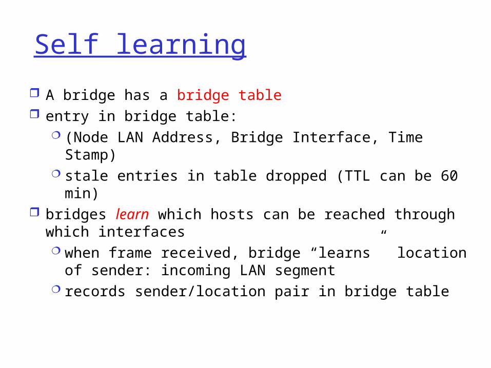
Self learning
A bridge has a bridge table entry in bridge table:
(Node LAN Address, Bridge Interface, Time Stamp) stale entries in table dropped (TTL can be 60 min)
bridges learn which hosts can be reached through which interfaces when frame received, bridge “learns” location of
sender: incoming LAN segment records sender/location pair in bridge table

Bridges
A bridge has a table used in filtering decisions

Filtering/ForwardingWhen bridge receives a frame:
index bridge table using MAC dest addressif entry found for destination
then{ if dest on segment from which frame arrived
then drop the frame else forward the frame on interface indicated } else flood
forward on all but the interface on which the frame arrived

Bridge example
Suppose C sends frame to D and D replies back with frame to C.
Bridge receives frame from C notes in bridge table that C is on interface 1 because D is not in table, bridge sends frame into
interfaces 2 and 3
frame received by D

Bridge Learning: example
D generates frame for C, sends bridge receives frame
notes in bridge table that D is on interface 2 bridge knows C is on interface 1, so selectively
forwards frame to interface 1

Interconnection without backbone
Not recommended for two reasons:- single point of failure at Computer Science hub- all traffic between EE and SE must path over CS segment

Backbone configuration
Recommended !

Loop ProblemTo increase reliability, add more bridges between 2 LANs
Solution: ?????

Bridges Spanning Tree for increased reliability, desirable to have redundant,
alternative paths from source to dest with multiple paths, cycles result - bridges may
multiply and forward frame forever solution: organize bridges in a spanning tree by
disabling subset of interfaces
Disabled

Some bridge features Isolates collision domains resulting in higher
total max throughput limitless number of nodes and geographical
coverage Can connect different Ethernet types Transparent (“plug-and-play”): no
configuration necessary

Bridges vs. Routers both store-and-forward devices
routers: network layer devices (examine network layer headers) bridges are link layer devices
routers maintain routing tables, implement routing algorithms
bridges maintain bridge tables, implement filtering, learning and spanning tree algorithms
Routers vs. Bridges
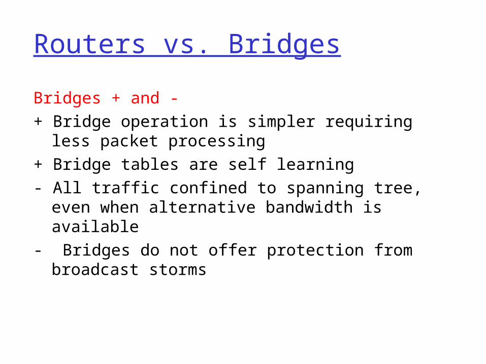
Bridges + and - + Bridge operation is simpler requiring less
packet processing+ Bridge tables are self learning - All traffic confined to spanning tree, even when
alternative bandwidth is available- Bridges do not offer protection from broadcast
storms

Routers vs. Bridges
Routers + and -+ arbitrary topologies can be supported, cycling is
limited by TTL counters (and good routing protocols)
+ provide protection against broadcast storms- require IP address configuration (not plug and play)- require higher packet processing
bridges do well in small (few hundred hosts) while routers used in large networks (thousands of hosts)

Backbone Networks
Bus backbone
• Star (or switched, or collapsed) backbone

Remote Bridges
A point-to-point link acts as a LAN in a remote
backbone connected by remote bridges

Virtual LANs
In many companies, organizational changes occur all the time LAN membership of an employee is
changed if he moves to another department. What if his office remains the same? => Need re-cabling
He remains in the same department but changes office => need re-cabling
Virtual LAN: a good way for logical re-wiring networks in software Need use specially-designed VLAN-aware
switches

(a) Four physical LANs organized into two VLANs by two bridges. (b) The same 15 machines organized into two VLANs by switches
VLAN: Example

VLAN: How to Distinguish VLANs
Each bridge/switch has a configuration table 3 methods
Every port is assigned a VLAN color• All machines to this port must belong to the same
VLAN Every MAC addr is assigned a VLAN color
• Not good for notebooks that can be docked anywhere Every layer-3 protocol or IP addr is assigned a
VLAN color• VLAN information is embedded in the the frame• Fundamental problem: non-independence of the layers
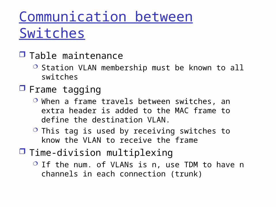
Communication between Switches Table maintenance
Station VLAN membership must be known to all switches
Frame tagging When a frame travels between switches, an extra
header is added to the MAC frame to define the destination VLAN.
This tag is used by receiving switches to know the VLAN to receive the frame
Time-division multiplexing If the num. of VLANs is n, use TDM to have n
channels in each connection (trunk)
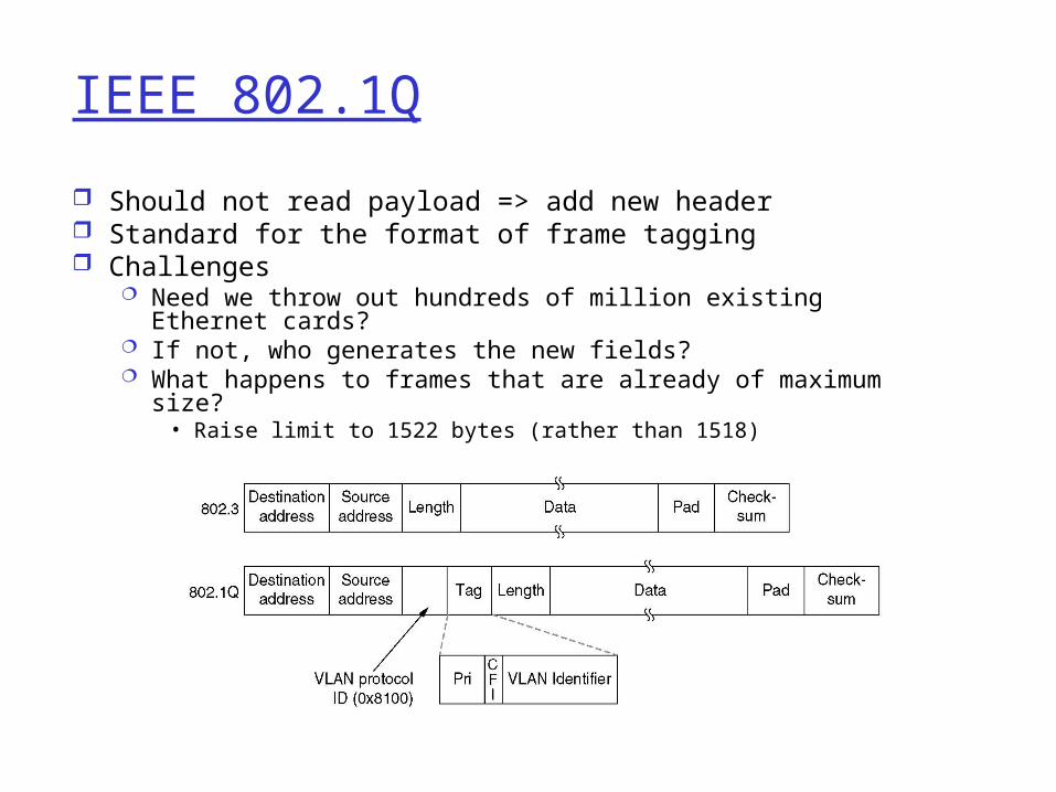
IEEE 802.1Q
Should not read payload => add new header Standard for the format of frame tagging Challenges
Need we throw out hundreds of million existing Ethernet cards?
If not, who generates the new fields? What happens to frames that are already of maximum size?
• Raise limit to 1522 bytes (rather than 1518)
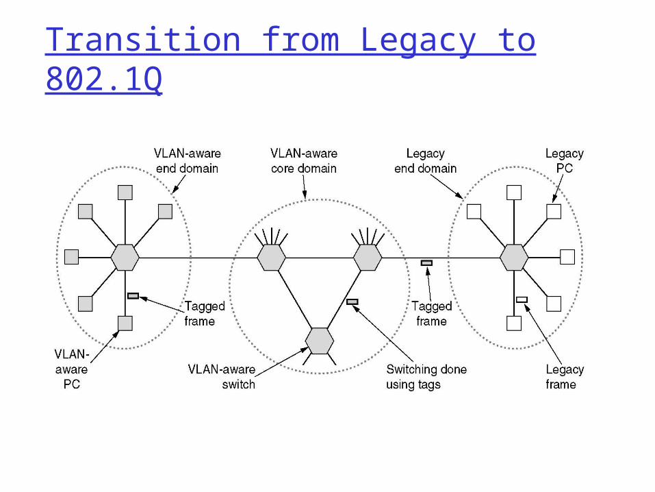
Transition from Legacy to 802.1Q

Ethernet Switches Essentially a multi-interface
bridge layer 2 (frame) forwarding,
filtering using LAN addresses Switching: A-to-A’ and B-to-
B’ simultaneously, no collisions
large number of interfaces often: individual hosts, star-
connected into switch Ethernet, but no
collisions!
Ethernet Switches
cut-through switching: frame forwarded from input to output port without awaiting for assembly of entire frameVs. store and forwardslight reduction in latency
combinations of shared/dedicated, 10/100/1000 Mbps interfaces

Not an atypical LAN (IP network)
Dedicated
Shared

Summary comparison
hubs bridges routers switches
traffi cisolation
no yes yes yes
plug & play yes yes no yes
optimalrouting
no no yes no
cutthrough
yes no no yes

Outline
LAN addresses and ARP Ethernet Hubs, bridges, and switches Wireless links and LANs PPP ATM
IEEE 802.11 Wireless LAN
802.11b 2.4-5 GHz unlicensed
radio spectrum up to 11 Mbps direct sequence
spread spectrum (DSSS) in physical layer
• all hosts use same chipping code
widely deployed, using base stations
802.11a 5-6 GHz range up to 54 Mbps
802.11g 2.4-5 GHz range up to 54 Mbps
All use CSMA/CA for multiple access
All have base-station and ad-hoc network versions

Base station approach Wireless host communicates with a base
station base station = access point (AP)
Basic Service Set (BSS) (a.k.a. “cell”) contains: wireless hosts access point (AP): base station
BSSs combined to form distribution system (DS)

Ad Hoc Network approach
No AP (i.e., base station) wireless hosts communicate with each other
to get packet from wireless host A to B may need to route through wireless hosts X,Y,Z
Applications: “laptop” meeting in conference room, car interconnection of “personal” devices battlefield
IETF (Internet Engineering Task Force) MANET www.ietf.org(Mobile Ad hoc Networks) working group
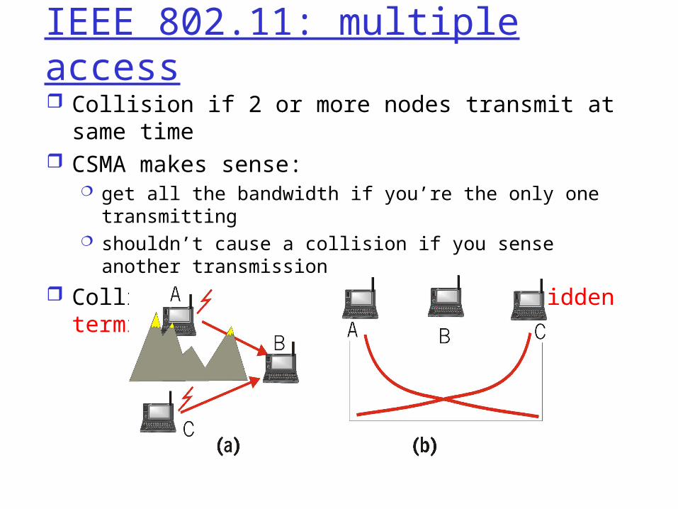
IEEE 802.11: multiple access Collision if 2 or more nodes transmit at same
time CSMA makes sense:
get all the bandwidth if you’re the only one transmitting shouldn’t cause a collision if you sense another
transmission
Collision detection doesn’t work: hidden terminal problem

IEEE 802.11 MAC Protocol: CSMA/CA
802.11 CSMA: sender- if sense channel idle for
DISF sec. then transmit entire frame
(no collision detection)-if sense channel busy
then binary backoff802.11 CSMA receiver- if received OK return ACK after SIFS (ACK is needed due to
hidden terminal problem)

Collision avoidance mechanisms Problem:
two nodes, hidden from each other, transmit complete frames to base station
wasted bandwidth for long duration !
Solution: small reservation packets nodes track reservation interval with
internal “network allocation vector” (NAV)

Collision Avoidance: RTS-CTS exchange sender transmits short
RTS (request to send) packet: indicates duration of transmission
receiver replies with short CTS (clear to send) packet notifying (possibly
hidden) nodes
hidden nodes will not transmit for specified duration: NAV

Collision Avoidance: RTS-CTS exchange
RTS and CTS short: collisions less likely, of
shorter duration end result similar to
collision detection IEEE 802.11 allows:
CSMA CSMA/CA: reservations polling from AP
A word about Bluetooth
Low-power, small radius, wireless networking technology 10-100 meters
omnidirectional not line-of-sight
infrared
Interconnects gadgets 2.4-2.5 GHz
unlicensed radio band up to 721 kbps
Interference from wireless LANs, digital cordless phones, microwave ovens: frequency hopping
helps
MAC protocol supports: error correction ARQ
Each node has a 12-bit address

Outline
LAN addresses and ARP Ethernet Hubs, bridges, and switches Wireless links and LANs PPP ATM

Point to Point Data Link Control one sender, one receiver, one link: easier than
broadcast link: no Media Access Control no need for explicit MAC addressing e.g., dialup link, ISDN line
popular point-to-point DLC protocols: PPP (point-to-point protocol) HDLC: High level data link control (Data link
used to be considered “high layer” in protocol stack!
Objective: Detailed study on a (simple) protocol - PPP

PPP Design Requirements [RFC 1557]
packet framing: encapsulation of network-layer datagram in data link frame carry network layer data of any network layer
protocol (not just IP) at same time ability to demultiplex upwards
bit transparency: must carry any bit pattern in the data field
error detection (no correction) connection liveness: detect, signal link failure to
network layer network layer address negotiation: endpoint can
learn/configure each other’s network address

PPP non-requirements
no error correction/recovery no flow control out of order delivery OK no need to support multipoint links (e.g.,
polling)
Error recovery, flow control, data re-ordering all relegated to higher layers!

PPP Data Frame
Flag: delimiter (framing) Address: does nothing (only one option) Control: does nothing; in the future possible
multiple control fields Protocol: upper layer protocol to which frame
delivered (eg, PPP-LCP, IP, IPCP, etc)

PPP Data Frame
info: upper layer data being carried check: cyclic redundancy check for error
detection

Byte Stuffing “ data transparency” requirement: data field
must be allowed to include flag pattern <01111110> Q: is received <01111110> data or flag?
Sender: adds “stuffs” -- extra < 01111110> after each < 01111110> data byte
Receiver: two 01111110 bytes: discard first byte,
continue data reception single 01111110: flag byte

Byte Stuffing
flag bytepatternin datato send
flag byte pattern plusstuffed byte in transmitted data

PPP Data Control ProtocolBefore exchanging network-
layer data, data link peers must
configure PPP link (max. frame length, authentication)
learn/configure network layer information
for IP: carry IP Control Protocol (IPCP) msgs (protocol field: 8021) to configure/learn IP address

Outline
LAN addresses and ARP Ethernet Hubs, bridges, and switches Wireless links and LANs PPP ATM

Asynchronous Transfer Mode: ATM 1990’s/00 standard for high-speed
(155Mbps to 622 Mbps and higher) Broadband Integrated Service Digital Network architecture
Goal: integrated, end-end transport of carry voice, video, data meeting timing/QoS requirements of voice,
video (versus Internet best-effort model) “next generation” telephony: technical roots
in telephone world packet-switching (fixed length packets, called
“cells”) using virtual circuits
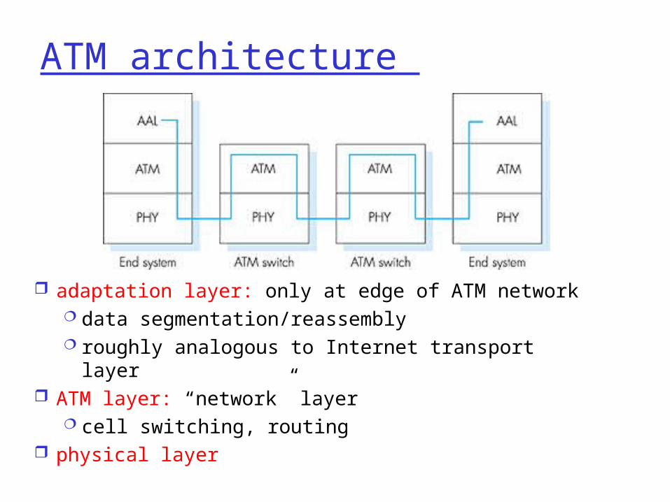
ATM architecture
adaptation layer: only at edge of ATM network data segmentation/reassembly roughly analogous to Internet transport layer
ATM layer: “network” layer cell switching, routing
physical layer

ATM: network or link layer?Vision: end-to-end
transport: “ATM from desktop to desktop” ATM is a network
technologyReality: used to connect
IP backbone routers “IP over ATM” ATM as switched
link layer, connecting IP routers
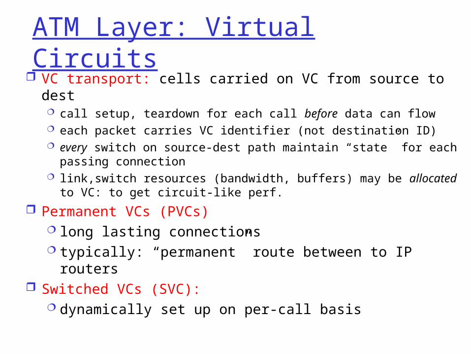
ATM Layer: Virtual Circuits VC transport: cells carried on VC from source to dest
call setup, teardown for each call before data can flow each packet carries VC identifier (not destination ID) every switch on source-dest path maintain “state” for each
passing connection link,switch resources (bandwidth, buffers) may be allocated
to VC: to get circuit-like perf.
Permanent VCs (PVCs) long lasting connections typically: “permanent” route between to IP routers
Switched VCs (SVC): dynamically set up on per-call basis

ATM VCs
Advantages of ATM VC approach: QoS performance guarantee for connection
mapped to VC (bandwidth, delay, delay jitter)
Drawbacks of ATM VC approach: Inefficient support of datagram traffic one PVC between each source/dest pair)
does not scale (N*2 connections needed) SVC introduces call setup latency,
processing overhead for short lived connections

ATM Layer: ATM cell 5-byte ATM cell header 48-byte payload
Why?: small payload -> short cell-creation delay for digitized voice
halfway between 32 and 64 (compromise!)
Cell header
Cell format

ATM cell header
VCI: virtual channel ID will change from link to link thru net
PT: Payload type (e.g. RM cell versus data cell)
CLP: Cell Loss Priority bit CLP = 1 implies low priority cell, can be
discarded if congestion HEC: Header Error Checksum
cyclic redundancy check

ATM Physical Layer (more)
Two pieces (sublayers) of physical layer: Transmission Convergence Sublayer (TCS): adapts
ATM layer above to PMD sublayer below Physical Medium Dependent: depends on physical
medium being used
TCS Functions: Header checksum generation: 8 bits CRC Cell delineation With “unstructured” PMD sublayer, transmission
of idle cells when no data cells to send

IP-Over-ATMClassic IP only 3 “networks” (e.g., LAN segments) MAC (802.3) and IP addresses
IP over ATM replace “network”
(e.g., LAN segment) with ATM network
ATM addresses, IP addresses
ATMnetwork
EthernetLANs
EthernetLANs
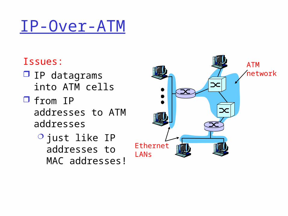
IP-Over-ATM
Issues: IP datagrams into
ATM cells from IP addresses
to ATM addresses just like IP
addresses to MAC addresses!
ATMnetwork
EthernetLANs

Datagram Journey in IP-over-ATM Network at Source Host:
IP layer maps between IP, ATM dest address (using ARP) passes datagram to AAL5 (ATM Adaptation Layer 5) AAL5 encapsulates data, segments cells, passes to ATM
layer
ATM network: moves cell along VC to destination at Destination Host:
AAL5 reassembles cells into original datagram if CRC OK, datagram is passed to IP

Summary
principles behind data link layer services: error detection, correction sharing a broadcast channel: multiple access link layer addressing, ARP
link layer technologies: Ethernet, hubs, bridges, switches,IEEE 802.11 LANs, PPP, ATM
journey down the protocol stack now OVER! future stops: multimedia, security,
network management