computer networks prof. ashok k agrawala
TRANSCRIPT

CMSC 417
Computer Networks
Prof. Ashok K Agrawala
© 2016 Ashok Agrawala
Set 7
October 16 CMSC417 Set 7 1

The Transport Layer
October 16 2CMSC417 Set 7
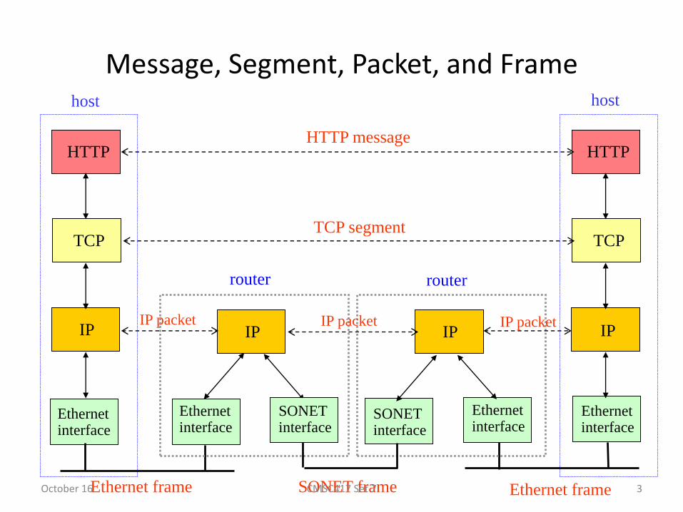
Message, Segment, Packet, and Frame
HTTP
TCP
IP
Ethernetinterface
HTTP
TCP
IP
Ethernetinterface
IP IP
Ethernetinterface
Ethernetinterface
SONETinterface
SONETinterface
host host
router router
HTTP message
TCP segment
IP packet IP packetIP packet
Ethernet frame Ethernet frameSONET frameOctober 16 3CMSC417 Set 7

The Transport Layer
CN5E by Tanenbaum & Wetherall, © Pearson Education-Prentice Hall and D. Wetherall, 2011
Responsible for delivering data across networks with the desired reliability or quality
Physical
Link
Network
Transport
Application

The Transport Service
• Services Provided to the Upper Layers
• Transport Service Primitives
• Berkeley Sockets
• An Example of Socket Programming:
– An Internet File Server
October 16 5CMSC417 Set 7

Services Provided to the Upper Layers (1)
Transport layer adds reliability to the network layer
– Offers connectionless (e.g., UDP) and connection-oriented (e.g, TCP) service to applications
CN5E by Tanenbaum & Wetherall, © Pearson Education-Prentice Hall and D. Wetherall, 2011
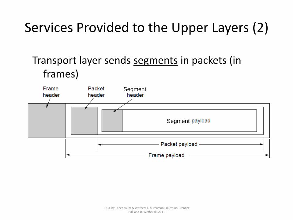
Services Provided to the Upper Layers (2)
CN5E by Tanenbaum & Wetherall, © Pearson Education-Prentice Hall and D. Wetherall, 2011
Transport layer sends segments in packets (in frames)
Segment
Segment

Berkeley Sockets
CN5E by Tanenbaum & Wetherall, © Pearson Education-Prentice Hall and D. Wetherall, 2011
Very widely used primitives started with TCP on UNIX
– Notion of “sockets” as transport endpoints
– Like simple set plus SOCKET, BIND, and ACCEPT

Elements of Transport Protocols
CN5E by Tanenbaum & Wetherall, © Pearson Education-Prentice Hall and D. Wetherall, 2011
– Addressing »
– Connection establishment »
– Connection release »
– Error control and flow control »
– Multiplexing »
– Crash recovery »

Transport Protocol
(a) Environment of the data link layer.(b) Environment of the transport layer.
Packets may be lost, delayed, duplicated, out of order, etc.
October 16 10CMSC417 Set 7

Addressing
CN5E by Tanenbaum & Wetherall, © Pearson Education-Prentice Hall and D.
Wetherall, 2011
•Transport layer adds TSAPs
•Multiple clients and servers can run on a host with a single network (IP) address
•TSAPs are ports for TCP/UDP

Addressing (2)
How a user process in host 1 establishes a connection with a mail server in host 2 via a process server.
Connection Establishment
• Connect
– Expect confirmation that one and only one connection has been established
– In a reasonable time
• Send Connection Request
• Expect Connection Accepted
• Segments (Packets) may be lost, corrupted, delayed, out of order, duplicated.
October 16 CMSC417 Set 7 13

Connection Establishment (1)
CN5E by Tanenbaum & Wetherall, © Pearson Education-Prentice Hall and D. Wetherall, 2011
Key problem is to ensure reliability even though packets may be lost, corrupted, delayed, and duplicated
– Detect corrupted packets (error detection – e.g. checksum)
– Detect lost packets (Time Out)
– Identify retransmitted packets (sequence numbers)

Sequence Numbers
CN5E by Tanenbaum & Wetherall, © Pearson Education-Prentice Hall and D. Wetherall, 2011
• An integer number with finite number of bits
• 8 bits => 256
• 16 bits => 64K
• Roll Over
• How long does it take?
• Can there be old duplicates in the system?
Approach:
– Don’t reuse sequence numbers within twice the MSL (Maximum Segment Lifetime) of 2T=240 secs
– Three-way handshake for establishing connection

Connection Establishment (2)
CN5E by Tanenbaum & Wetherall, © Pearson Education-Prentice Hall and D. Wetherall, 2011
Use a sequence number space large enough that it will not wrap, even when sending at full rate– Clock (high bits) advances & keeps state over crash
Need seq. number not to
wrap within T seconds
Need seq. number not to
climb too slowly for too long

Connection Establishment (3)
CN5E by Tanenbaum & Wetherall, © Pearson Education-Prentice Hall and D.
Wetherall, 2011
Three-way handshake used for initial packet
– Since no state from previous connection
– Both hosts contribute fresh seq. numbers
– CR = Connect Request
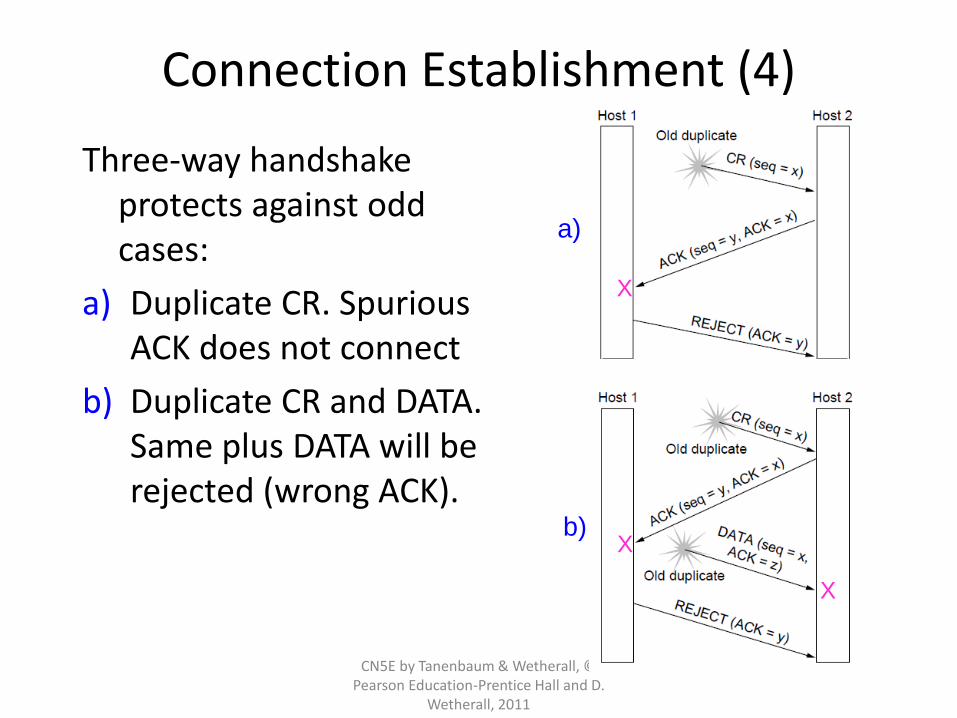
Connection Establishment (4)
CN5E by Tanenbaum & Wetherall, © Pearson Education-Prentice Hall and D.
Wetherall, 2011
Three-way handshake protects against odd cases:
a) Duplicate CR. Spurious ACK does not connect
b) Duplicate CR and DATA. Same plus DATA will be rejected (wrong ACK).
a)
b)
X
X
X

Connection Release (1)
CN5E by Tanenbaum & Wetherall, © Pearson Education-Prentice Hall and D.
Wetherall, 2011
Key problem is to ensure reliability while releasing
Asymmetric release (when one side breaks connection) is abrupt and may lose data
X

Connection Release (2)
CN5E by Tanenbaum & Wetherall, © Pearson Education-Prentice Hall and D. Wetherall, 2011
Symmetric release (both sides agree to release) can’t be handled solely by the transport layer
– Two-army problem shows pitfall of agreement
Attack? Attack?

Connection Release (3)
CN5E by Tanenbaum & Wetherall, © Pearson Education-Prentice Hall and D.
Wetherall, 2011
Normal release sequence, initiated by transport user on Host 1
– DR=Disconnect Request
– Both DRs are ACKed by the other side

Connection Release (4)
CN5E by Tanenbaum & Wetherall, © Pearson Education-Prentice Hall and D. Wetherall, 2011
Error cases are handled with timer and retransmission
Final ACK lost,
Host 2 times outLost DR causes
retransmissions
Extreme: Many lost
DRs cause both
hosts to timeout

Flow Control• Use Sliding Window• Buffering
– Sender buffers all TPDUs until acknowledged– TPDU lost by the network
• Unreliable service• Receiver not having buffer
• How should buffers be managed– Dedicate– Acquire when needed
• Traffic– Low bandwidth, Bursty – buffer at sender – acquire at receiver– High bandwidth, smooth – Buffer at both ends
• Exchange Buffer information
October 16 CMSC417 Set 7 23

Error Control and Flow Control (1)
CN5E by Tanenbaum & Wetherall, © Pearson Education-Prentice Hall and D. Wetherall, 2011
Foundation for error control is a sliding window (from Link layer) with checksums and retransmissions
Flow control manages buffering at sender/receiver
– Issue is that data goes to/from the network and applications at different times
– Window tells sender available buffering at receiver
– Makes a variable-size sliding window

Error Control and Flow Control (2)
CN5E by Tanenbaum & Wetherall, © Pearson Education-Prentice Hall and D. Wetherall, 2011
Different buffer strategies trade efficiency / complexity
a) Chained fixed-
size buffersb) Chained variable-
size buffers
c) One large circular buffer
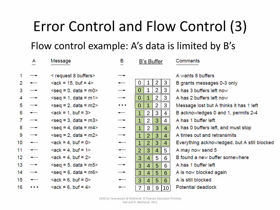
Error Control and Flow Control (3)
CN5E by Tanenbaum & Wetherall, © Pearson Education-Prentice Hall and D. Wetherall, 2011
Flow control example: A’s data is limited by B’s buffer
0 1 2 3
0 1 2 3
0 1 2 3
0 1 2 3
1 2 3 4
1 2 3 4
1 2 3 4
1 2 3 4
1 2 3 4
2 3 4 5
3 4 5 6
3 4 5 6
3 4 5 6
3 4 5 6
7 8 9 10
B’s Buffer

Reliable Transmission
• Transfer frames without errors
– Error Correction
– Error Detection
– Discard frames with error
• Acknowledgements and Timeouts
• Retransmission
• ARQ – Automatic Repeat Request
2013 CMSC417 Set 4 27

Stop and Wait with 1-bit Seq No
2013 CMSC417 Set 4 28

Stop and Wait Protocols
• Simple
• Low Throughput
– One Frame per RTT
• Increase throughput by having more frames in flight
– Sliding Window Protocol
2013 CMSC417 Set 4 29

Stop and Wait
2013 CMSC417 Set 4 30
Duplicate
Frames
Stop and Wait Protocol
• http://www.cs.stir.ac.uk/~kjt/software/comms/jasper/ABP.html
• http://www.cs.stir.ac.uk/~kjt/software/comms/jasper/ABRA.html
2013 CMSC417 Set 4 31

Stop-and-Wait – Error-free channel
CMSC417 Set 4
Protocol (p2) ensures sender can’t outpace receiver:
– Receiver returns a dummy frame (ack) when ready
– Only one frame out at a time – called stop-and-wait
– We added flow control!
Sender waits to for ack after
passing frame to physical layer
Receiver sends ack after passing
frame to network layer

Stop-and-Wait – Noisy channel (1)
CMSC417 Set 4
ARQ (Automatic Repeat reQuest) adds error control
– Receiver acks frames that are correctly delivered
– Sender sets timer and resends frame if no ack)
For correctness, frames and acks must be numbered
– Else receiver can’t tell retransmission (due to lost ackor early timer) from new frame
– For stop-and-wait, 2 numbers (1 bit) are sufficient
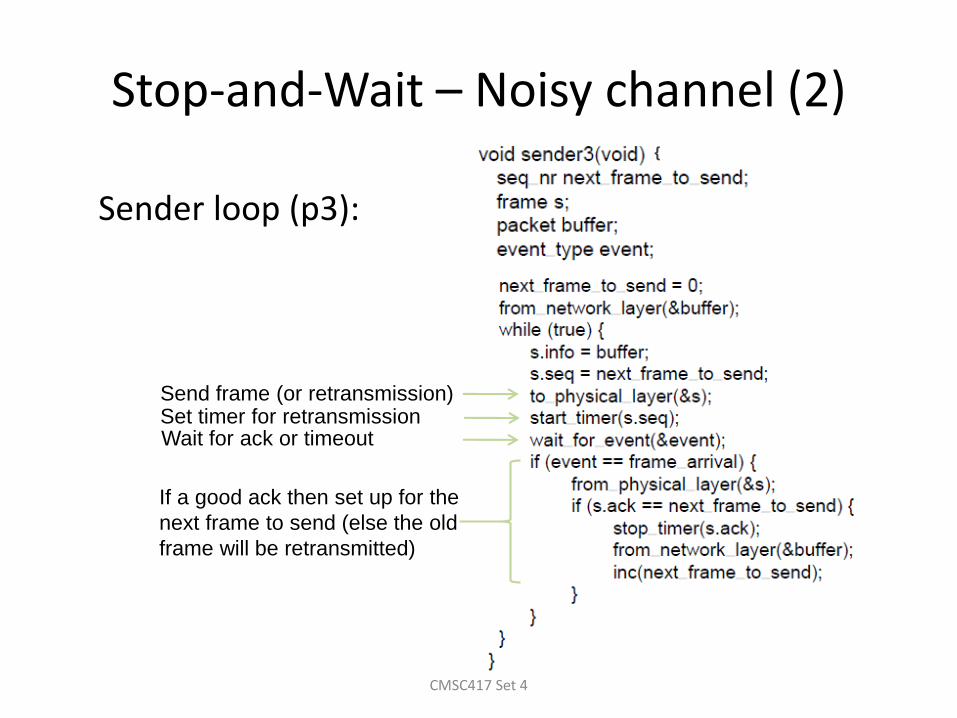
Stop-and-Wait – Noisy channel (2)
CMSC417 Set 4
Sender loop (p3):
Send frame (or retransmission)Set timer for retransmissionWait for ack or timeout
If a good ack then set up for the
next frame to send (else the old
frame will be retransmitted)
{

Stop-and-Wait – Noisy channel (3)
CMSC417 Set 4
Receiver loop (p3):
Wait for a frame
If it’s new then take
it and advance
expected frame
Ack current frame

Sliding Window Protocols
CMSC417 Set 4
– Sliding Window concept »
– One-bit Sliding Window »
– Go-Back-N »
– Selective Repeat »

Sliding Window concept (1)
CMSC417 Set 4
Sender maintains window of frames it can send
– Needs to buffer them for possible retransmission
– Window advances with next acknowledgements
Receiver maintains window of frames it can receive
– Needs to keep buffer space for arrivals
– Window advances with in-order arrivals

Go-Back-N (1)
CMSC417 Set 4
Receiver only accepts/acks frames that arrive in order:
– Discards frames that follow a missing/errored frame
– Sender times out and resends all outstanding frames

Go-Back-N (2)
CMSC417 Set 4
Tradeoff made for Go-Back-N:
– Simple strategy for receiver; needs only 1 frame
– Wastes link bandwidth for errors with large windows; entire window is retransmitted
Implemented as p5 (see code in book)

Selective Repeat (1)
CMSC417 Set 4
Receiver accepts frames anywhere in receive window
– Cumulative ack indicates highest in-order frame
– NAK (negative ack) causes sender retransmission of a missing frame before a timeout resends window

Selective Repeat (2)
CMSC417 Set 4
Tradeoff made for Selective Repeat:
– More complex than Go-Back-N due to buffering at receiver and multiple timers at sender
– More efficient use of link bandwidth as only lost frames are resent (with low error rates)
Implemented as p6 (see code in book)

Selective Repeat (3)
CMSC417 Set 4
For correctness, we require:
– Sequence numbers (s) at least twice the window (w)
Originals OriginalsRetransmits Retransmits
Error case (s=8, w=7) – too
few sequence numbers
Correct (s=8, w=4) – enough
sequence numbers
New receive window overlaps
old – retransmits ambiguous
New and old receive window
don’t overlap – no ambiguity

Sliding Window Protocols
CMSC417 Set 4
http://www.ccs-labs.org/teaching/rn/animations/gbn_sr/
http://www.cs.stir.ac.uk/~kjt/software/comms/jasper/SWP3.html
http://www.cs.stir.ac.uk/~kjt/software/comms/jasper/SWP5.html
http://www2.rad.com/networks/2004/sliding_window/

Throughput limits
• Buffers
• Bandwidth – subnet’s carrying capacity
– K TPDUs per second
– X paths then total of XK
• Flow control to manage
– Manage window size• If network can handle c TPDUs/sec and Cycle time is r then the
window size should be cr
October 16 CMSC417 Set 7 44

Multiplexing
• Kinds of transport / network sharing that can occur:– Multiplexing: connections share a network address
– Inverse multiplexing: addresses share a connection
CN5E by Tanenbaum & Wetherall, © Pearson Education-Prentice Hall and D.
Wetherall, 2011
Multiplexing Inverse Multiplexing

Crash Recovery
• Network Failures
– Transport layer handles• Connectionless
• Connection oriented
• Host Crashes
– Server crash and may reboot• Send broadcast asking clients to inform of prior connections ( stop
and wait protocol)
– Client – one TPDU outstanding or none outstanding
October 16 CMSC417 Set 7 46

Crash Recovery
CN5E by Tanenbaum & Wetherall, © Pearson Education-Prentice Hall and D. Wetherall, 2011
Application needs to help recovering from a crash
– Transport can fail since A(ck) / W(rite) not atomic

Congestion Control
CN5E by Tanenbaum & Wetherall, © Pearson Education-Prentice Hall and D. Wetherall, 2011
Two layers are responsible for congestion control:
• Transport layer, controls the offered load [here]
• Network layer, experiences congestion [previous]
– Desirable bandwidth allocation »
– Regulating the sending rate »
– Wireless issues »

Desirable Bandwidth Allocation (1)
CN5E by Tanenbaum & Wetherall, © Pearson Education-Prentice Hall and D. Wetherall, 2011
Efficient use of bandwidth gives high goodput, low delay
Delay begins to rise sharply
when congestion sets inGoodput rises more slowly than
load when congestion sets in

Desirable Bandwidth Allocation (2)
CN5E by Tanenbaum & Wetherall, © Pearson Education-Prentice Hall and D. Wetherall, 2011
Fair use gives bandwidth to all flows (no starvation)
– Max-min fairness gives equal shares of bottleneck
Bottleneck link

Desirable Bandwidth Allocation (3)
CN5E by Tanenbaum & Wetherall, © Pearson Education-Prentice Hall and D. Wetherall, 2011
We want bandwidth levels to converge quickly when traffic patterns change
Flow 1 slows quickly
when Flow 2 starts
Flow 1 speeds up
quickly when Flow 2
stops

Regulating the Sending Rate (1)
CN5E by Tanenbaum & Wetherall, © Pearson Education-Prentice Hall and D.
Wetherall, 2011
Sender may need to slow down for different reasons:
– Flow control, when the receiver is not fast enough [right]
– Congestion, when the network is not fast enough [over]
A fast network feeding a low-capacity receiver
flow control is needed

Regulating the Sending Rate (2)
CN5E by Tanenbaum & Wetherall, © Pearson Education-Prentice Hall and D.
Wetherall, 2011
Our focus is dealing with this problem –congestion
A slow network feeding a high-capacity receiver
congestion control is needed

Regulating the Sending Rate (3)
CN5E by Tanenbaum & Wetherall, © Pearson Education-Prentice Hall and D. Wetherall, 2011
Different congestion signals the network may use to tell the transport endpoint to slow down (or speed up)

Regulating the Sending Rate (3)
CN5E by Tanenbaum & Wetherall, © Pearson Education-Prentice Hall and D. Wetherall, 2011
If two flows increase/decrease their bandwidth in the same way when the network signals free/busy they will not converge to a fair allocation
+/– percentage
+ /– constant

Regulating the Sending Rate (4)
CN5E by Tanenbaum & Wetherall, © Pearson Education-Prentice Hall and D. Wetherall, 2011
The AIMD (Additive Increase Multiplicative Decrease) control law does converge to a fair and efficient point!
– TCP uses AIMD for this reason
User 1’s bandwidth
User
2’s
bandw
idth
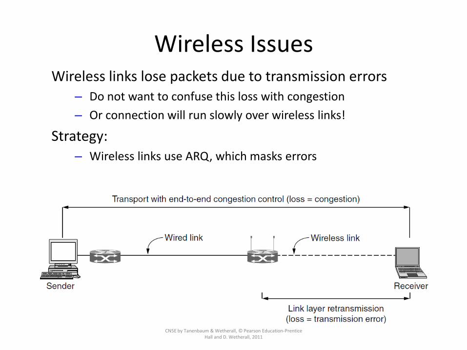
Wireless Issues
CN5E by Tanenbaum & Wetherall, © Pearson Education-Prentice Hall and D. Wetherall, 2011
Wireless links lose packets due to transmission errors– Do not want to confuse this loss with congestion
– Or connection will run slowly over wireless links!
Strategy:– Wireless links use ARQ, which masks errors

A Simple Transport Protocol
• The Example Service Primitives
• The Example Transport Entity
• The Example as a Finite State Machine
October 16 58CMSC417 Set 7
Similar to TCP but simpler

Service Primitives
• Connect– Parameters – local and remote TSAPs
– Caller is blocked
– If connection succeeds the caller is unblocked and transmission starts
• Listen – specifies a TSAP to listen to
• Disconnect
• Send
• Receive
• ** Library procedures
October 16 CMSC417 Set 7 59

Service Primitives
• Connum=LISTEN(local)
• Connum=Connect(local,remote)
• Status = Send(Connum, buffer,bytes)
– No Connection, illegal buffer address, negative count
• Status = Receive(Connum, buffer, bytes)
• Status = Disconnect(Connum)
October 16 CMSC417 Set 7 60
The Transport Entity
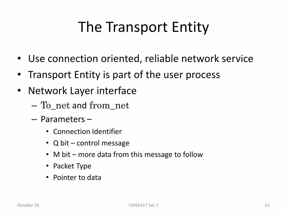
• Use connection oriented, reliable network service
• Transport Entity is part of the user process
• Network Layer interface
– To_net and from_net
– Parameters –• Connection Identifier
• Q bit – control message
• M bit – more data from this message to follow
• Packet Type
• Pointer to data
October 16 CMSC417 Set 7 61

The Example Transport Entity
The network layer packets used in our example.
October 16 62CMSC417 Set 7

The Example Transport Entity (2)
Each connection is in one of seven states:
1. Idle – Connection not established yet.
2. Waiting – CONNECT has been executed, CALL REQUEST sent.
3. Queued – A CALL REQUEST has arrived; no LISTEN yet.
4. Established – The connection has been established.
5. Sending – The user is waiting for permission to send a packet.
6. Receiving – A RECEIVE has been done.
7. DISCONNECTING – a DISCONNECT has been done locally.October 16 63CMSC417 Set 7

State Transitions
• A primitive is executed
• A packet arrives
• A timer expires
October 16 CMSC417 Set 7 64

Internet Protocols – UDP
CN5E by Tanenbaum & Wetherall, © Pearson Education-Prentice Hall and D. Wetherall, 2011
– Introduction to UDP »
– Remote Procedure Call »
– Real-Time Transport »

User Datagram Protocol
• Connectionless
• Does not do
– Flow control
– Error control
– Retransmissions
• Useful in client-server situations
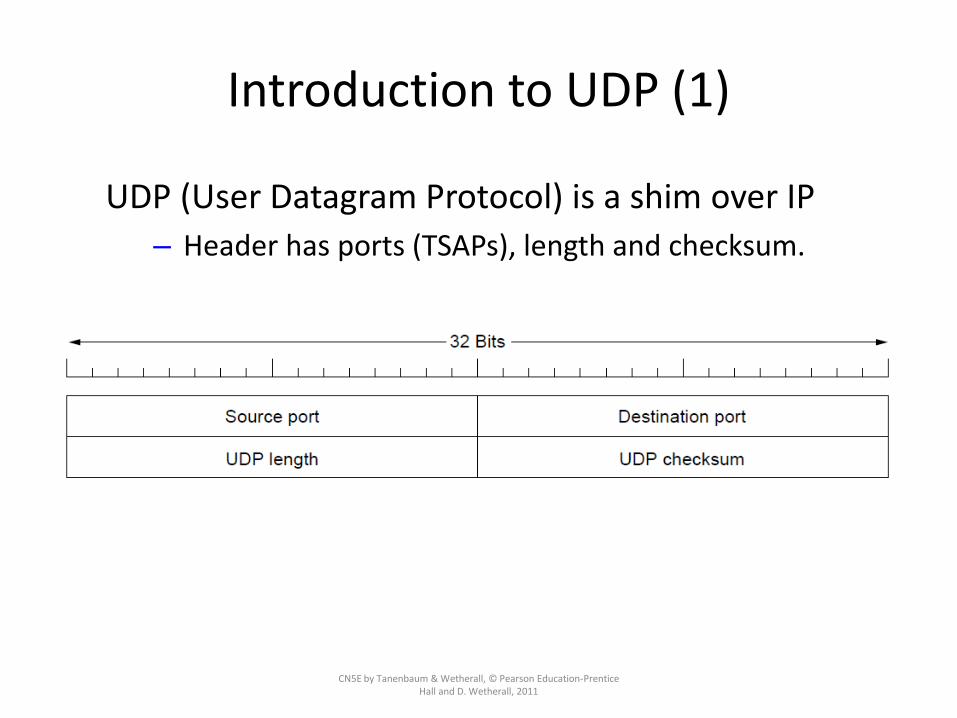
• Sends segments consisting of an 8-byte header followed by the payload
October 16 CMSC417 Set 7 66
Introduction to UDP (1)
CN5E by Tanenbaum & Wetherall, © Pearson Education-Prentice Hall and D. Wetherall, 2011
UDP (User Datagram Protocol) is a shim over IP
– Header has ports (TSAPs), length and checksum.

Introduction to UDP (2)
CN5E by Tanenbaum & Wetherall, © Pearson Education-Prentice Hall and D. Wetherall, 2011
Checksum covers UDP segment and IP pseudoheader– Fields that change in the network are zeroed out
– Provides an end-to-end delivery check

RPC (Remote Procedure Call)• RPC connects applications over the network with the familiar
abstraction of procedure calls– Stubs package parameters/results into a message
– UDP with retransmissions is a low-latency transport
CN5E by Tanenbaum & Wetherall, © Pearson Education-Prentice Hall and D.
Wetherall, 2011
Limitations of RPC
• Pointers
• Weakly Typed languages – variable length arrays
• Not possible always to deduce parameter types
• Global variables
October 16 CMSC417 Set 7 70

Real-Time Transport (1)
CN5E by Tanenbaum & Wetherall, © Pearson Education-Prentice Hall and D. Wetherall, 2011
RTP (Real-time Transport Protocol) provides support for sending real-time media over UDP
– Often implemented as part of the application

Real-Time Transport (2)
CN5E by Tanenbaum & Wetherall, © Pearson Education-Prentice Hall and D. Wetherall, 2011
RTP header contains fields to describe the type of media and synchronize it across multiple streams
– RTCP sister protocol helps with management tasks
RTP Header Fields
• Ver – 2
• P – Packet padded to multiple of 4 bytes
• X – extension header present
• CC – number of contributing sources
• M bit – Application specific marker
• Payload Type – encoding used
• Sequence Number
• Time stamp – produced by the source
• Synchronizations Source Identifier – which stream the packet belongs to
October 16 CMSC417 Set 7 73

RTP Profiles
• RTP payloads may contain multiple samples coded in any way the application wants
• Profiles – to support interworking– Single Audio Stream
– Multiple encoding formats may be supported• 8-bit pcm samples at 8KHz
• Delta encoding
• Predictive encoding
• MP3
• …
October 16 CMSC417 Set 7 74

RTCP – Real-time Transport Control Protocol
• Control Protocol for RTP
• Does not transport any data
• Handles:– Feedback
• Delay
• Jitter
• Bandwidth
• Congestion, etc.
– Synchronization• Interstream Synchronization – Different clocks, drifts, etc.
– User Interface
October 16 CMSC417 Set 7 75

Real-Time Transport (3)
CN5E by Tanenbaum & Wetherall, © Pearson Education-Prentice Hall and D. Wetherall, 2011
Buffer at receiver is used to delay packets and absorb jitter so that streaming media is played out smoothly
Packet 8’s network delay is
too large for buffer to help
Constant rate
Variable rate
Constant rate

Real-Time Transport (3)
CN5E by Tanenbaum & Wetherall, © Pearson Education-Prentice Hall and D. Wetherall, 2011
High jitter, or more variation in delay, requires a larger playout buffer to avoid playout misses– Propagation delay does not affect buffer size
Buffer
Misses

Internet Protocols – TCP
CN5E by Tanenbaum & Wetherall, © Pearson Education-Prentice Hall and D. Wetherall, 2011
– The TCP service model »
– The TCP segment header »
– TCP connection establishment »
– TCP connection state modeling »
– TCP sliding window »
– TCP timer management »
– TCP congestion control »

TCP
• Reliable end-to-end byte stream over an unreliable internetwork
• Dynamically adapt to the properties of the network
• Robust
• RFC 793 – 1122 and 1323
October 16 CMSC417 Set 7 79

TCP Transport Entity
• Implemented as– Library procedures
– User process, or
– Part of the kernel
• Accepts data streams from local processes
• Breaks them into segments of >64KB (usually 1460 bytes)
• Sends each piece in a separate IP packet
• On receive side – reconstruct the original byte stream and give to a process.
• Must recover from errors – time outs, retransmissions, etc.
October 16 CMSC417 Set 7 80

TCP Service Model
• End points called sockets
– Socket number • IP address of the host
• 16-bit number (called the port)
• Connection Oriented – Full Duplex, Point-to-Point
– Establish a connection between sockets
– An socket may be used for multiple connections at the same time
– Connection (socket1, socket2)
October 16 CMSC417 Set 7 81

Berkeley Sockets
The socket primitives for TCP.
October 16 82CMSC417 Set 7

The TCP Service Model (1)
CN5E by Tanenbaum & Wetherall, © Pearson Education-Prentice Hall and D. Wetherall, 2011
TCP provides applications with a reliable byte stream between processes; it is the workhorse of the Internet– Popular servers run on well-known ports

Internet Daemon
• Attaches to multiple well-known ports and waits
• When a connection comes in it forks off a new process and executes the appropriate daemon
• That daemon handles the request
October 16 CMSC417 Set 7 84

The TCP Service Model
(a) Four 512-byte segments sent as separate IP datagrams.(b) The 2048 bytes of data delivered to the application in a single
READ CALL.
October 16 85CMSC417 Set 7
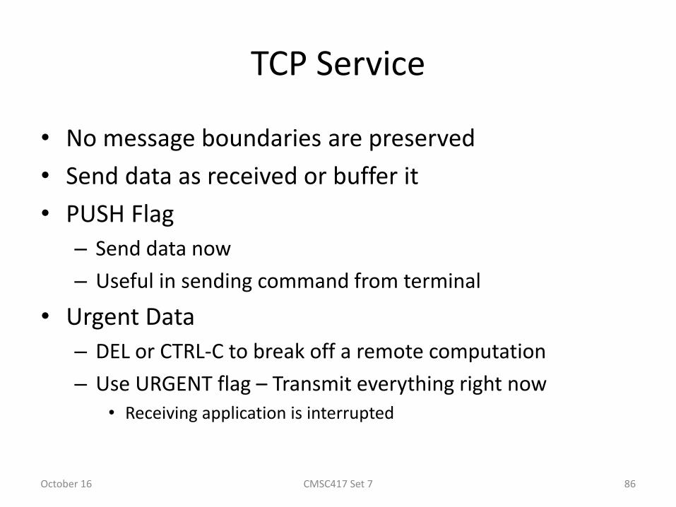
TCP Service
• No message boundaries are preserved
• Send data as received or buffer it
• PUSH Flag
– Send data now
– Useful in sending command from terminal
• Urgent Data
– DEL or CTRL-C to break off a remote computation
– Use URGENT flag – Transmit everything right now• Receiving application is interrupted
October 16 CMSC417 Set 7 86

TCP Protocol
• Exchange segments– 20 byte header (plus optional parts)
– 0 or more data bytes
• Accumulate data from several writes into one segment
• May split data from one write into multiple segments
• Each segment, including the header, must be <65515 byte IP payload
• Each network has MTU- Maximum Transfer Unit– Each segment must be less than or equal to MTU
October 16 CMSC417 Set 7 87

TCP Protocol
• TCP uses sliding window protocol
• Sequence numbers are for bytes not segments
• Sending – start a timer
• Receiving – send an ack with sequence number = next sequence number expected
October 16 CMSC417 Set 7 88

The TCP Segment Header
TCP Header.October 16 89CMSC417 Set 7

TCP Segment Header
• Source and Destination Port
• Sequence number
• Acknowledgement Number– Next byte expected
• TCP Header Length – Number of 32 bit words in TCP header
• Flags– URG – set to 1 if Urgent Pointer is in use
• Used to indicate a byte offset from the current seq no at which urgent data care there
– ACK – set to 1 when ack no is valid
– PSH – Push bit
– RST – Reset
– SYN – Used for connection establishment
– FIN – Used to close a connection
October 16 CMSC417 Set 7 90

The TCP Segment Header (2)
• The pseudoheader included in the TCP checksum
• Checksum the header, the data and the pseudoheader
• Add all 16-bit words in 1’s complement and then take 1’s complement of the sum
• To check calculate on the entire segment and result should be 0.
October 16 91CMSC417 Set 7

TCP Window
• Window size tells how many bytes may be sent starting at the byte acknowledged
– If 0 means do not send now.
– May send a segment with same ack no and non-zero window size.
October 16 CMSC417 Set 7 92

Maximum segment Size
• All hosts are required to accept TCP segments of 536+20 =556 bytes
• May negotiate max segment size using options.
• Another negotiable parameter – Window Scale
– May shift to the left by up to 14 bits
– Giving a max window size of 230 bytes
October 16 CMSC417 Set 7 93

Connection Establishment
• Uses three-way handshake
• Server passively listens
– LISTEN and ACCEPT primitives
• Client executes CONNECT
– Send a TCP Segment with SYN bit on and ACK bit off.
• Check to see if there is a process listening
– If not send a RST
– If yes, then give the segment to the process
– If accepted – send an ACK message
October 16 CMSC417 Set 7 94

TCP Connection Establishment
CN5E by Tanenbaum & Wetherall, © Pearson Education-Prentice Hall and D. Wetherall, 2011
TCP sets up connections with the three-way handshake– Release is symmetric, also as described before
Normal case Simultaneous connect

TCP Connection State Modeling (1)
CN5E by Tanenbaum & Wetherall, © Pearson Education-Prentice Hall and D. Wetherall, 2011
The TCP connection finite state machine has more states than our simple example from earlier.
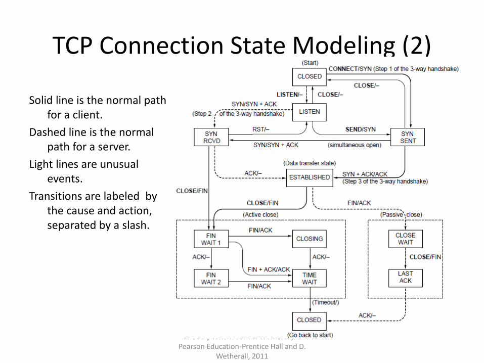
TCP Connection State Modeling (2)
CN5E by Tanenbaum & Wetherall, © Pearson Education-Prentice Hall and D.
Wetherall, 2011
Solid line is the normal path for a client.
Dashed line is the normal path for a server.
Light lines are unusual events.
Transitions are labeled by the cause and action, separated by a slash.

Connection Release
• Think of the connection as a pair of simplex connections
– Each is released independently
• Either party sends a segment with FIN bit set
• When FIN acked that direction is shut down
October 16 CMSC417 Set 7 98

TCP Sliding Window (1)
CN5E by Tanenbaum & Wetherall, © Pearson Education-Prentice Hall and D.
Wetherall, 2011
TCP adds flow control to the sliding window as before
– ACK + WIN is the sender’s limit
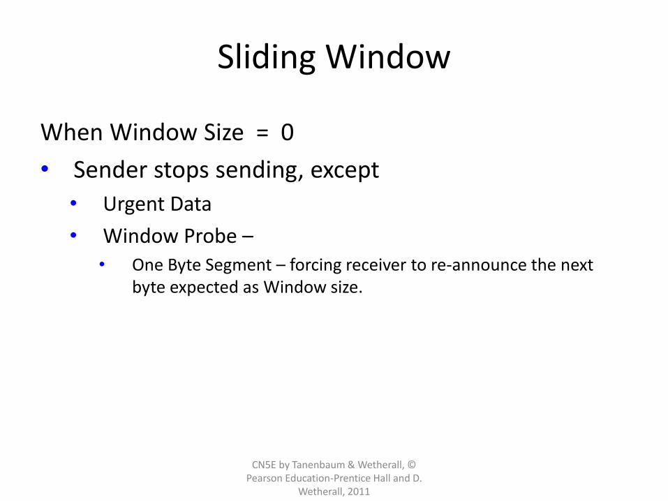
Sliding Window
CN5E by Tanenbaum & Wetherall, © Pearson Education-Prentice Hall and D.
Wetherall, 2011
When Window Size = 0
• Sender stops sending, except
• Urgent Data
• Window Probe –• One Byte Segment – forcing receiver to re-announce the next
byte expected as Window size.

Example Situation Telnet
• 1 Byte
– 21 Byte Segment
– 41 Byte Packet
• 40 Byte Ack
• 40 Byte Ack
• 41 Byte Echo
CN5E by Tanenbaum & Wetherall, © Pearson Education-Prentice Hall and D.
Wetherall, 2011
162 Bytes on the network for one byte data
Delayed Ack - 500 ms

TCP Sliding Window (2)
CN5E by Tanenbaum & Wetherall, © Pearson Education-Prentice Hall and D. Wetherall, 2011
Need to add special cases to avoid unwanted behavior
– E.g., silly window syndrome [below]
Receiver application reads single bytes, so
sender always sends one byte segments

Handling Silly Window Problem
• Delay ack and window updates for 500 ms.
• Nagle’s Algorithm
– When data comes in one byte at a time
• Send the first byte and buffer the rest till the outstanding byte is acknowledged
• Then send all the buffered characters in one TCP segment
– Mouse movements have to be sent – Burst does not work well.
• Clark’s Solution
– Wait until decent amount of space available then advertise
• Max segment size or half buffer
– Sender not send tiny segments
October 16 CMSC417 Set 7 103

Timer Management
• TCP uses multiple timers– Most important is the retransmission timer– What value to set it at??
• Round Trip time– Highly variable– Varies over time– Have to track it– Estimate it– M is a new measurement– = 7/8– Use bRTT for retransmission timer– Initial values of b were 2 – make is proportional to standard
deviation of M
October 16 CMSC417 Set 7 104
(1 )RTT RTT M

TCP Timer Management
CN5E by Tanenbaum & Wetherall, © Pearson Education-Prentice Hall and D. Wetherall, 2011
TCP estimates retransmit timer from segment RTTs
– Tracks both average and variance (for Internet case)
– Timeout is set to average plus 4 x variance
LAN case – small,
regular RTT
Internet case –
large, varied RTT

Timer Management
• Jacobson Approach
• Mean deviation estimate
• D = gD + ( 1-g) |RTT – M|
• Timeout = RTT + 4 D
• What to do on retransmissions– Do not know if the ack is for the first or second
• Karn Algorithm– Do not update RTT on any segments that have been
retransmitted
October 16 CMSC417 Set 7 106

Persistence Timer
• Receiver sends a window of 0
• Later sends a window size but that packet is lost
– Both wait
• Persistence Timer
– When it goes off – sender sends a probe request to receiver to get a window size
– If still zero – continue to wait and reset persistence timer
• Keepalive Timer
– When a connection is idle for a long time – check if the other side is still there
October 16 CMSC417 Set 7 107

TCP Congestion Control
• Congestion – a function of total number of packets in the network, and where they are
• First step – detection– Is packet loss an indication of congestion??
– All TCP algorithms assume timeouts are caused by congestion
• Initial steps– When connection is established – use suitable window size
• Loss will not occur due to buffers at receiver
• Two issues– Network Capacity
– Receiver Capacity
October 16 CMSC417 Set 7 108

TCP Congestion Control
• Network Capacity and Receiver Capacity• Maintain two windows
– Receiver window– Congestion window– Use the min ( Receiver window and Congestion window)
• Initially– Sender sets congestion window to MSS (Max Seg Size)– If acked add one more MSS – 2 now– Repeat for each acked MSS– Congestion window grows exponentially– If timeout – go back to previous window size– SLOW START
October 16 CMSC417 Set 7 109

Internet Congestion Control
• Use a Threshold – initially 64 KB
• When a timeout occurs set threshold to half the current congestion window and reset congestion window to 1 MSS
• Use slow start till the threshold is reached
• Then successful transmissions grow congestion window linearly
October 16 CMSC417 Set 7 110

TCP Congestion Control (1)
CN5E by Tanenbaum & Wetherall, © Pearson Education-Prentice Hall and D. Wetherall, 2011
TCP uses AIMD with loss signal to control congestion
– Implemented as a congestion window (cwnd) for the number of segments that may be in the network
– Uses several mechanisms that work together
Name Mechanism Purpose
ACK clock Congestion window (cwnd) Smooth out packet bursts
Slow-start Double cwnd each RTT Rapidly increase send rate to
reach roughly the right level
Additive
Increase
Increase cwnd by 1 packet
each RTT
Slowly increase send rate to
probe at about the right level
Fast
retransmit
/ recovery
Resend lost packet after 3
duplicate ACKs; send new
packet for each new ACK
Recover from a lost packet
without stopping ACK clock

TCP Congestion Control (2)
CN5E by Tanenbaum & Wetherall, © Pearson Education-Prentice Hall and D. Wetherall, 2011
Congestion window controls the sending rate
– Rate is cwnd / RTT; window can stop sender quickly
– ACK clock (regular receipt of ACKs) paces traffic and smoothes out sender bursts
ACKs pace new segments into
the network and smooth bursts

TCP Congestion Control (3)
CN5E by Tanenbaum & Wetherall, © Pearson Education-Prentice Hall and D. Wetherall, 2011
Slow start grows congestion window exponentially
– Doubles every RTT while keeping ACK clock going
Increment cwnd for
each new ACK

TCP Congestion Control (4)
CN5E by Tanenbaum & Wetherall, © Pearson Education-Prentice Hall and D.
Wetherall, 2011
ACK
Additive increase grows cwnd slowly
– Adds 1 every RTT
– Keeps ACK clock

TCP Congestion Control (5)
CN5E by Tanenbaum & Wetherall, © Pearson Education-Prentice Hall and D. Wetherall, 2011
Slow start followed by additive increase (TCP Tahoe)
– Threshold is half of previous loss cwnd
Loss causes timeout;
ACK clock has stopped
so slow-start again

TCP Congestion Control (6)• With fast recovery, we get the classic sawtooth (TCP
Reno)
– Retransmit lost packet after 3 duplicate ACKs
– New packet for each dup. ACK until loss is repaired
CN5E by Tanenbaum & Wetherall, © Pearson Education-Prentice Hall and D.
Wetherall, 2011
The ACK clock doesn’t stop,
so no need to slow-start

TCP Congestion Control (7)
CN5E by Tanenbaum & Wetherall, © Pearson Education-Prentice Hall and D. Wetherall, 2011
SACK (Selective ACKs) extend ACKs with a vector to describe received segments and hence losses
– Allows for more accurate retransmissions / recovery
No way for us to know that 2 and
5 were lost with only ACKs

Wireless TCP and UDP
Splitting a TCP connection into two connections.
October 16 118CMSC417 Set 7
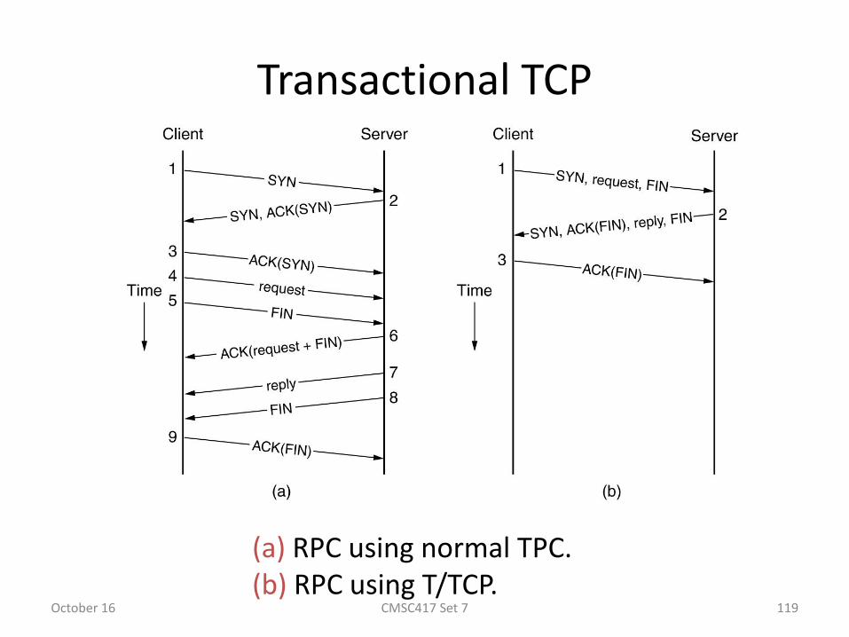
Transactional TCP
(a) RPC using normal TPC.(b) RPC using T/TCP.
October 16 119CMSC417 Set 7

Performance Issues
CN5E by Tanenbaum & Wetherall, © Pearson Education-Prentice Hall and D. Wetherall, 2011
Many strategies for getting good performance have been learned over time
– Performance problems »
– Measuring network performance »
– Host design for fast networks »
– Fast segment processing »
– Header compression »
– Protocols for “long fat” networks »

Performance Problems
CN5E by Tanenbaum & Wetherall, © Pearson Education-Prentice Hall and D. Wetherall, 2011
Unexpected loads often interact with protocols to cause performance problems
– Need to find the situations and improve the protocols
Examples:
– Broadcast storm: one broadcast triggers another
– Synchronization: a building of computers all contact the DHCP server together after a power failure
– Tiny packets: some situations can cause TCP to send many small packets instead of few large ones

Host Design for Fast Networks
CN5E by Tanenbaum & Wetherall, © Pearson Education-Prentice Hall and D. Wetherall, 2011
Poor host software can greatly slow down networks.
Rules of thumb for fast host software:
– Host speed more important than network speed
– Reduce packet count to reduce overhead
– Minimize data touching
– Minimize context switches
– Avoiding congestion is better than recovering from it
– Avoid timeouts

Fast Segment Processing (1)
CN5E by Tanenbaum & Wetherall, © Pearson Education-Prentice Hall and D. Wetherall, 2011
Speed up the common case with a fast path [pink]
– Handles packets with expected header; OK for others to run slowly
Segment
segment

Fast Segment Processing (2)
CN5E by Tanenbaum & Wetherall, © Pearson Education-Prentice Hall and D. Wetherall, 2011
Header fields are often the same from one packet to the next for a flow; copy/check them to speed up processing
IP header fields that are often the
same for a one-way flow (shaded)
TCP header fields that stay the
same for a one-way flow (shaded)

Fast TPDU Processing (3)
A timing wheel.October 16 129CMSC417 Set 7

Header Compression
CN5E by Tanenbaum & Wetherall, © Pearson Education-Prentice Hall and D. Wetherall, 2011
Overhead can be very large for small packets
– 40 bytes of header for RTP/UDP/IP VoIP packet
– Problematic for slow links, especially wireless
Header compression mitigates this problem
– Runs between Link and Network layer
– Omits fields that don’t change or change predictably
• 40 byte TCP/IP header 3 bytes of information
– Gives simple high-layer headers and efficient links

Protocols for “Long Fat” Networks (1)
CN5E by Tanenbaum & Wetherall, © Pearson Education-Prentice Hall and D. Wetherall, 2011
Networks with high bandwidth (“Fat”) and high delay (“Long”) can store much information inside the network
– Requires protocols with ample buffering and few RTTs, rather than reducing the bits on the wire
Starting to send 1 Mbit
San Diego Boston20ms after start 40ms after start

Protocols for “Long Fat” Networks (2)
CN5E by Tanenbaum & Wetherall, © Pearson Education-Prentice Hall and D. Wetherall, 2011
You can buy more bandwidth but not lower delay
– Need to shift ends (e.g., into cloud) to lower further
Minimum time to send and ACK a 1-Mbit file over a 4000-km line
Propagation delay

Delay Tolerant Networking
CN5E by Tanenbaum & Wetherall, © Pearson Education-Prentice Hall and D. Wetherall, 2011
DTNs (Delay Tolerant Networks) store messages inside the network until they can be delivered
– DTN Architecture »
– Bundle Protocol »

DTN Architecture (1)
CN5E by Tanenbaum & Wetherall, © Pearson Education-Prentice Hall and D. Wetherall, 2011
Messages called bundles are stored at DTN nodes while waiting for an intermittent link to become a contact
– Bundles might wait hours, not milliseconds in routers
– May be no working end-to-end path at any time

DTN Architecture (2)
CN5E by Tanenbaum & Wetherall, © Pearson Education-Prentice Hall and D. Wetherall, 2011
Example DTN connecting a satellite to a collection point

Bundle Protocol (1)
CN5E by Tanenbaum & Wetherall, © Pearson Education-Prentice Hall and D. Wetherall, 2011
The Bundle protocol uses TCP or other transports and provides a DTN service to applications

Bundle Protocol (2)
CN5E by Tanenbaum & Wetherall, © Pearson Education-Prentice Hall and D. Wetherall, 2011
Features of the bundle message format:• Dest./source add high-level addresses (not port/IP)
• Custody transfer shifts delivery responsibility
• Dictionary provides compression for efficiency